EP3874662B1 - Csi-rückkopplung zur datenübertragung über mehrere übertragungspunkte - Google Patents
Csi-rückkopplung zur datenübertragung über mehrere übertragungspunkte Download PDFInfo
- Publication number
- EP3874662B1 EP3874662B1 EP19829672.5A EP19829672A EP3874662B1 EP 3874662 B1 EP3874662 B1 EP 3874662B1 EP 19829672 A EP19829672 A EP 19829672A EP 3874662 B1 EP3874662 B1 EP 3874662B1
- Authority
- EP
- European Patent Office
- Prior art keywords
- csi
- resources
- nzp csi
- nzp
- trps
- Prior art date
- Legal status (The legal status is an assumption and is not a legal conclusion. Google has not performed a legal analysis and makes no representation as to the accuracy of the status listed.)
- Active
Links
Images



Classifications
-
- H—ELECTRICITY
- H04—ELECTRIC COMMUNICATION TECHNIQUE
- H04B—TRANSMISSION
- H04B7/00—Radio transmission systems, i.e. using radiation field
- H04B7/02—Diversity systems; Multi-antenna system, i.e. transmission or reception using multiple antennas
- H04B7/04—Diversity systems; Multi-antenna system, i.e. transmission or reception using multiple antennas using two or more spaced independent antennas
- H04B7/06—Diversity systems; Multi-antenna system, i.e. transmission or reception using multiple antennas using two or more spaced independent antennas at the transmitting station
- H04B7/0613—Diversity systems; Multi-antenna system, i.e. transmission or reception using multiple antennas using two or more spaced independent antennas at the transmitting station using simultaneous transmission
- H04B7/0615—Diversity systems; Multi-antenna system, i.e. transmission or reception using multiple antennas using two or more spaced independent antennas at the transmitting station using simultaneous transmission of weighted versions of same signal
- H04B7/0619—Diversity systems; Multi-antenna system, i.e. transmission or reception using multiple antennas using two or more spaced independent antennas at the transmitting station using simultaneous transmission of weighted versions of same signal using feedback from receiving side
- H04B7/0621—Feedback content
- H04B7/0626—Channel coefficients, e.g. channel state information [CSI]
-
- H—ELECTRICITY
- H04—ELECTRIC COMMUNICATION TECHNIQUE
- H04L—TRANSMISSION OF DIGITAL INFORMATION, e.g. TELEGRAPHIC COMMUNICATION
- H04L5/00—Arrangements affording multiple use of the transmission path
- H04L5/003—Arrangements for allocating sub-channels of the transmission path
- H04L5/0032—Distributed allocation, i.e. involving a plurality of allocating devices, each making partial allocation
- H04L5/0035—Resource allocation in a cooperative multipoint environment
-
- H—ELECTRICITY
- H04—ELECTRIC COMMUNICATION TECHNIQUE
- H04L—TRANSMISSION OF DIGITAL INFORMATION, e.g. TELEGRAPHIC COMMUNICATION
- H04L5/00—Arrangements affording multiple use of the transmission path
- H04L5/003—Arrangements for allocating sub-channels of the transmission path
- H04L5/0048—Allocation of pilot signals, i.e. of signals known to the receiver
- H04L5/005—Allocation of pilot signals, i.e. of signals known to the receiver of common pilots, i.e. pilots destined for multiple users or terminals
-
- H—ELECTRICITY
- H04—ELECTRIC COMMUNICATION TECHNIQUE
- H04L—TRANSMISSION OF DIGITAL INFORMATION, e.g. TELEGRAPHIC COMMUNICATION
- H04L5/00—Arrangements affording multiple use of the transmission path
- H04L5/0091—Signalling for the administration of the divided path, e.g. signalling of configuration information
-
- H—ELECTRICITY
- H04—ELECTRIC COMMUNICATION TECHNIQUE
- H04L—TRANSMISSION OF DIGITAL INFORMATION, e.g. TELEGRAPHIC COMMUNICATION
- H04L5/00—Arrangements affording multiple use of the transmission path
- H04L5/003—Arrangements for allocating sub-channels of the transmission path
- H04L5/0053—Allocation of signalling, i.e. of overhead other than pilot signals
- H04L5/0057—Physical resource allocation for CQI
Definitions
- next generation mobile wireless communication system (Fifth Generation (5G)), or New Radio (NR) will support a diverse set of use cases and a diverse set of deployment scenarios.
- low frequencies e.g., below 6 Gigahertz (GHz)
- very high frequencies e.g., up to tens of GHz.
- NR uses Cyclic Prefix Orthogonal Frequency Division Multiplexing (CP-OFDM) in the downlink from a network node (e.g., a NR base station (gNB), an enhanced or evolved Node B (eNB), or a base station) to a User Equipment (UE) and both CP-OFDM and Discrete Fourier Transform (DFT)-Spread Orthogonal Frequency Division Multiplexing (DFT-S-OFDM) in the uplink from a UE to a network node (e.g., gNB, eNB, or base station).
- CP-OFDM Cyclic Prefix Orthogonal Frequency Division Multiplexing
- UE User Equipment
- DFT-S-OFDM Discrete Fourier Transform
- DFT-S-OFDM Discrete Fourier Transform
- NR downlink and uplink are organized into equally-sized subframes of 1 millisecond (ms) each.
- a subframe is further divided into multiple slots of equal duration.
- OFDM Orthogonal Frequency Division Multiplexing
- Data scheduling in NR can be on a slot basis, as in LTE.
- Figure 1 illustrates an example NR time-domain structure with 15 kHz subcarrier spacing with a 14 symbol slot, where the first two symbols contain Physical Downlink Control Channel (PDCCH) and the rest contain Physical Data Channel (PDCH), i.e., either Physical Downlink Shared Channel (PDSCH) or Physical Uplink Shared Channel (PUSCH).
- PDCCH Physical Downlink Control Channel
- PDCH Physical Data Channel
- PDSCH Physical Downlink Shared Channel
- PUSCH Physical Uplink Shared Channel
- Different subcarrier spacing values are supported in NR.
- ⁇ f 15 kHz is the basic subcarrier spacing that is also used in LTE.
- the slot durations at different subcarrier spacings are shown in Table 1.
- Table 1 Slot length at different numerologies. Numerology Slot length RB BW 15 kHz 1 ms 180 kHz 30 kHz 0.5 ms 360 kHz 60 kHz 0.25 ms 720 kHz 120 kHz 125 ⁇ s 1.44 MHz 240 kHz 62.5 ⁇ s 2.88 MHz
- a system bandwidth is divided into Resource Blocks (RBs), each corresponds to twelve contiguous subcarriers.
- the RBs are numbered starting with 0 from one end of the system bandwidth.
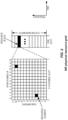
- the basic NR physical time-frequency resource grid is illustrated in Figure 2 , where only one RB within a 14 symbol slot is shown.
- One OFDM subcarrier during one OFDM symbol interval forms one Resource Element (RE).
- RE Resource Element
- Downlink transmissions are dynamically scheduled, i.e., in each slot the gNB transmits Downlink Control Information (DCI) over PDCCH about which UE data is to be transmitted to and which RBs in the current downlink slot the data is transmitted on.
- DCI Downlink Control Information
- PDCCH is typically transmitted in the first one or two OFDM symbols in each slot in NR.
- the UE data is carried on PDSCH.
- a UE first detects and decodes PDCCH and, upon decoding the PDCCH successfully, it then decodes the corresponding PDSCH based on the decoded DCI in the PDCCH.
- Uplink data transmissions are also dynamically scheduled using PDCCH. Similar to downlink, a UE first decodes uplink grants in PDCCH and then transmits data over PUSCH based the decoded control information in the uplink grant such as modulation order, coding rate, uplink resource allocation, etc.
- Multi-antenna techniques can significantly increase the data rates and reliability of a wireless communication system.
- the performance can be improved if both the transmitter and the receiver are equipped with multiple antennas, which results in a Multiple Input Multiple Output (MIMO) communication channel.
- MIMO Multiple Input Multiple Output
- Such systems and/or related techniques are commonly referred to as MIMO.
- a core component in NR is the support of MIMO antenna deployments and MIMO related techniques.
- Spatial multiplexing is one of the MIMO techniques used to achieve high data rates in favorable channel conditions.
- An illustration of the spatial multiplexing operation is provided in Figure 3 .
- the information carrying symbol vector s [ s 1 , s 2 , ... , s r ] T is multiplied by an N T x r precoder matrix W, which serves to distribute the transmit energy in a subspace of the N T (corresponding to N T antenna ports) dimensional vector space.
- the precoder matrix is typically selected from a codebook of possible precoder matrices, and typically indicated by means of a Precoder Matrix Indicator (PMI), which specifies a unique precoder matrix in the codebook for a given number of symbol streams.
- the rsymbols in the symbol vector s each correspond to a MIMO layer, and r is referred to as the transmission rank. In this way, spatial multiplexing is achieved since multiple symbols can be transmitted simultaneously over the same time and frequency RE.
- the number of symbols r is typically adapted to suit the current channel properties.
- the precoder W can be a wideband precoder, which is constant over frequency, or frequency selective, i.e. different over frequency.
- the precoder matrix is often chosen to match the characteristics of the N R x N T MIMO channel matrix H n , resulting in so-called channel dependent precoding. This is also commonly referred to as closed-loop precoding and essentially strives for focusing the transmit energy into a subspace which is strong in the sense of conveying much of the transmitted energy to the UE.
- the precoder matrix may also be selected to strive for orthogonalizing the channel, meaning that, after proper linear equalization at the UE, the inter-layer interference is reduced.
- the transmission rank and thus the number of spatially multiplexed layers, is reflected in the number of columns of the precoder.
- the transmission rank is also dependent on the Signal to Interference plus Noise Ratio (SINR) observed at the UE.
- SINR Signal to Interference plus Noise Ratio
- SINR Signal to Interference plus Noise Ratio
- a higher SINR is required for transmissions with higher ranks.
- it is important that a transmission rank that matches the channel properties as well as the interference is selected.
- the precoding matrix, the transmission rank, and the channel quality are part of Channel State Information (CSI), which is typically measured by a UE and fed back to a network node or gNB.
- CSI Channel State Information
- SU-MIMO Single User MIMO
- MU-MIMO Multi-User MIMO
- SU-MIMO When all the data layers are transmitted to one UE, it is referred to as SU-MIMO. On the other hand, when the data layers are transmitted to multiple UEs, it is referred to as MU-MIMO.
- MU-MIMO is possible when, for example, two UEs are in different areas of a cell such that they can be separated through different precoders (or beamforming) at the gNB, the two UEs may be served on the same time-frequency resources (i.e. Physical RBs (PRBs)) by using different precoders or beams.
- PRBs Physical RBs
- NR data transmission over multiple MIMO layers is shown in Figure 4 .
- either one codeword or two codewords is used.
- One codeword is used when the total number of layers is equal or less than four, two codewords are used when the number of layers is more than four.
- Each codeword contains the encoded data bits of a Transport Block (TB).
- TB Transport Block
- the scrambled bits are mapped to complex-valued modulation symbols d q 0 , ... , d q M symb q ⁇ 1 for codeword q .
- a Demodulation Reference Signal (DMRS), also referred to as a DMRS port, is transmitted along each data layer.
- DMRS Demodulation Reference Signal
- a UE can be configured with multiple CSI reporting settings and multiple CSI-RS resource settings.
- Each resource setting can contain multiple resource sets, and each resource set can contain up to eight CSI-RS resources.
- each CSI reporting setting it contains at least the following information:
- the CSI-RS resource set in a CSI reporting setting contains multiple CSI-RS resources
- one of the CSI-RS resources is selected by a UE and a CRI is also reported by the UE to indicate to the gNB about the selected CSI-RS resource in the resource set, together with RI, PMI, and CQI associated with the selected CSI-RS resource.
- more than one CSI reporting setting each with a different CSI-RS resource set for channel measurement and/or resource set for interference measurement, can be configured and triggered at the same time.
- multiple CSI reports are aggregated and sent from the UE to the gNB in a single PUSCH.
- DPS is supported in which data for a UE can be sent over different Transmission Points (TRPs) in different slots.
- TRPs Transmission Points
- the gNB may request the UE to measure and feedback downlink CSI for each of the TRPs, and the gNB then decides the TRP for data transmission to the UE. Since different TRPs may have different configurations for CSI-RS and other downlink reference signals such as Synchronization Signal Block (SSB), the available REs in a slot may also be different. Furthermore, since the different TRPs may be physically in different locations, the propagation channels to the UE can also be different.
- SSB Synchronization Signal Block
- the QCL information is used by a UE to apply large scale channel properties associated with the downlink reference signals (CSI-RS or SSB) to DMRS based channel estimation for PDSCH reception.
- CSI-RS downlink reference signals
- SSB downlink reference signals
- NC-JT refers to MIMO data transmission over multiple TRPs in which different MIMO layers are transmitted over different TRPs.
- An example is shown in Figure 6 , where a PDSCH is sent to a UE over two TRPs, each carrying one codeword.
- the UE can support up to four MIMO layers but there is a maximum of two MIMO layers from each TRP.
- the peak data rate to the UE can be increased, as up to four aggregated layers from the two TRPs can be used. This is beneficial when the traffic load, and thus the resource utilization, is low in each TRP.
- the scheme can also be beneficial in the case where the UE is in Line of Sight (LOS) of both the TRPs and the rank per TRP is limited even when there are more transmit antennas available at each TRP.
- LOS Line of Sight
- NC-JT is supported in LTE with two TRPs, each having up to eight antenna ports.
- a UE is configured with a CSI process with two NZP CSI-RS resources, one for each TRP, and one interference measurement resource.
- the UE calculates CSI per NZP CSI-RS resource and reports a pair of RIs, (RI1, RI2), a pair of PMIs, (PMI1, PMI2), and a pair of CQIs, (CQI1, CQI2), by considering the mutual interference between the two codewords from the two TRPs.
- MCSs Modulation and Coding Schemes
- An advanced receiver with Codeword Level Interference Cancellation can be used at the UE. Furthermore, when one codeword is in error, only that codeword needs to be re-transmitted. It also implies that maximum TRPs can be supported as only two codewords are supported in LTE and NR.
- An alternative approach is to use a single codeword over multiple TRPs.
- An example is shown in Figure 7 , where different layers are transmitted from three TRPs. This allows data transmission over more than two TRPs.
- a gNB may configure a UE with two CSI reporting settings, one for DPS and the other for NC-JT. The UE then feeds back two CSI reports, one for DPS and the other for NC-JT. The gNB can decide whether to use DPS or NC-JT based on other information available at the gNB.
- the UE would feedback a single CSI report consisting of at least an indicator of "Number of Selected Resources", i.e. NSRI, which indicates how many resources are selected along with a set of the selected CRIs, i.e. ⁇ CRT 1 , ..., CRI NRI ⁇ .
- multi-TRP transmission for improved data throughput such as DPS and NC-JT discussed above (which is referred to herein as spatial multiplexing based multi-TRP transmission)
- another application of multi-TRP transmission is to provide increased reliability of data transmission, which is important in some mission critical applications such as auto driving or industrial control.
- a same data packet may be transmitted over multiple TRPs as shown Figure 8 .
- Either the same resource or different resources may be used in different TRPs.
- Soft combining may be performed at the UE.
- different MIMO layers would be used to carry the same data from different TRPs and a MIMO receiver is needed at the UE to separate the layers.
- the same codeword with different redundancy versions may be transmitted from different TRPs and soft combining is performed at the UE.
- the same PDSCH may simply be transmitted over multiple TRPs, which is transparent to the UE. This type of multi-TRP transmission is referred to herein as diversity based multi-TRP transmission.
- the conventional CSI feedback mechanism e.g., the CSI feedback mechanisms for LTE
- the conventional CSI feedback mechanism are less than ideal when considering both DPS based multi-TRP transmission and NC-JT and when considering UE selection of M out of N TRPs.
- CSI feedback for multi-TRP discloses an evaluation of CSI feedback for non-coherent joint transmission. The following observations were made. Observation 1: Both NC-JT and DPS hypotheses need to be supported for multi-TRP CSI feedback. Observation 2: To indicate QCL with corresponding DMRS, each TRP must transmit CSI-RS in separate CSI-RS resources. Observation 3: TRPs participating in NC-JT can be equipped with different antennas and require different codebooks. Observation 4: It is beneficial for the UE to dynamically select how many TRPs shall participate in the NC-JT.
- CSI-RS resource selection within a TRP must be differentiated from selection of multiple CSI-RS resource corresponding to different TRPs for NC-JT hypothesis. Based on the discussion in the document, extensions of the NR CSI feedback framework to support NC-JT were proposed.
- a CSI Report Setting can be linked with more than one Resource Setting for channel measurement: the CSI Report Setting associates each Resource Setting with a precoder codebook; a CSI Report Setting is further configured with a set of hypotheses for channel measurement, wherein each hypothesis selects a subset of the linked Resource Settings for channel measurement and where the UE selects one hypothesis from the set as part of the CSI report; and for the selected Resource Settings, the UE determines PMI, RI and if applicable CRI for each Resource Setting jointly, assuming the layers from CSI-RS resources in different Resource Settings mutually interfere.
- Proposal 2 For CSI feedback with NC-JT hypothesis, the CSI Report Setting contains information on if single or multiple PDSCH shall be assumed for CQI calculation.
- Proposal 3 CSI feedback for NC-JT is contained in a single report, and not split up in per-TRP CSI reports on separate PUCCH/PUSCH transmissions.
- a radio access node examples include, but are not limited to, a base station (e.g., a New Radio (NR) base station (gNB) in a Third Generation Partnership Project (3GPP) Fifth Generation (5G) NR network or an enhanced or evolved Node B (eNB) in a 3GPP Long Term Evolution (LTE) network), a high-power or macro base station, a low-power base station (e.g., a micro base station, a pico base station, a home eNB, or the like), and a relay node.
- a base station e.g., a New Radio (NR) base station (gNB) in a Third Generation Partnership Project (3GPP) Fifth Generation (5G) NR network or an enhanced or evolved Node B (eNB) in a 3GPP Long Term Evolution (LTE) network
- a high-power or macro base station e.g., a micro base station, a pico base station, a home eNB, or the like
- a "core network node” is any type of node in a core network.
- Some examples of a core network node include, e.g., a Mobility Management Entity (MME), a Packet Data Network Gateway (P-GW), a Service Capability Exposure Function (SCEF), or the like.
- MME Mobility Management Entity
- P-GW Packet Data Network Gateway
- SCEF Service Capability Exposure Function
- a “wireless device” is any type of device that has access to (i.e., is served by) a cellular communications network by wirelessly transmitting and/or receiving signals to a radio access node(s).
- a wireless device include, but are not limited to, a User Equipment device (UE) in a 3GPP network and a Machine Type Communication (MTC) device.
- UE User Equipment device
- MTC Machine Type Communication
- DPS Dynamic Point Selection
- NTC-JT Non-Coherent Joint Transmission
- CSI Channel State Information
- the NC-JT specified in LTE is limited to two TRPs, each with up to eight antenna ports, and TRP selection is done by the eNB, i.e. no dynamic UE selection of two TRPs from more than two TRP candidates.
- the UE is allowed to select M out of N TRPs or select one from multiple transmission hypotheses, an issue is that the CSI payload can be different for different values of M or different hypotheses.
- PUSCH Physical Uplink Shared Channel
- Certain embodiments may provide one or more of the following technical advantage(s).
- the solutions allow a UE to select the best TRPs for data transmission over multiple TRPs and feed back the corresponding CSI, while allowing the gNB to decode the CSI feedback correctly without any ambiguity.
- M is also signaled to the UE, either explicitly or implicitly.
- RRC Radio Resource Control
- the CSI payload size is deterministic and is known to both the gNB and the UE.
- the number of selected TRPs may be reduced, for example from three to one, so that the second part of the CSI can fit in the scheduled PUSCH resource.
- the CSI report configuration includes an instruction if the UE shall report CSI according to the assumption on diversity-based transmission or spatial multiplexing-based transmission.
- the UE may in some such embodiments be configured with two (or more) CSI-ReportConfigs to report two sets of CSI, one for each assumption.
- Figure 10 illustrates the operation of a base station (e.g., gNB) and a UE in accordance with at least some aspects of the embodiments described above.
- the base station may be, e.g., a base station 902 or 906 and the UE may be, e.g., a UE 912.
- the base station sends, to the UE, a configuration of either: (a) N CSI-RS resource settings containing N NZP CSI-RS resources each associated with a different one of N TRPs or (b) N sets of NZP CSI-RS resources each associated with a different one of the N TRPs (step 1000).
- the base station sends, to the UE, a request for CSI feedback (step 1002).
- the base station further configures the UE with a list of transmission hypothesis over the configured NZP CSI-RS resources.
- the list of hypothesis comprises NC-JT, DPS, or diversity combining over one or more of the NZP CSI-RS resources.
- selecting the preferred subset comprises selecting one hypothesis out of the list of the hypothesis.
- reporting the CSI further comprises reporting the selected hypothesis.
- selecting the preferred subset at the UE comprises comparing data throughputs and selecting the TRPs that can provide the maximum throughput.
- Figure 11 illustrates the operation of a base station (e.g., gNB) and a UE in accordance with at least some aspects of the embodiments described above. Note that optional steps are indicated with dashed lines. This embodiment is substantially the same as that of Figure 10 other than "N" being replaced by "one or more” and the steps being optional to indicate that not all steps are required in all embodiments or implementations.
- a base station e.g., gNB
- the base station sends, to the UE, a configuration of either: (a) one or more CSI-RS resource settings containing one or more NZP CSI-RS resources each associated with a different one of one or more TRPs or (b) one or more sets of NZP CSI-RS resources each associated with a different one of the one or more TRPs (step 1100).
- the base station sends, to the UE, a request for CSI feedback (step 1102).
- the UE selects a preferred subset of the NZP CSI-RS resources (step 1104).
- the selected preferred subset of NZP CSI-RS resources then corresponds to a preferred subset of the one or more TRPs.
- the UE then reports CSI to the base station based on the selected preferred subset of the NZP CSI-RS resources (step 1106).
- the radio access node 1200 includes one or more radio units 1210 that each includes one or more transmitters 1212 and one or more receivers 1214 coupled to one or more antennas 1216.
- the radio units 1210 may be referred to or be part of radio interface circuitry.
- the radio unit(s) 1210 is external to the control system 1202 and connected to the control system 1202 via, e.g., a wired connection (e.g., an optical cable).
- the radio unit(s) 1210 and potentially the antenna(s) 1216 are integrated together with the control system 1202.
- the one or more processors 1204 operate to provide one or more functions of a radio access node 1200 as described herein.
- the function(s) are implemented in software that is stored, e.g., in the memory 1206 and executed by the one or more processors 1204.
- Figure 13 is a schematic block diagram that illustrates a virtualized embodiment of the radio access node 1200 according to some embodiments of the present disclosure. This discussion is equally applicable to other types of network nodes. Further, other types of network nodes may have similar virtualized architectures.
- a "virtualized" radio access node is an implementation of the radio access node 1200 in which at least a portion of the functionality of the radio access node 1200 is implemented as a virtual component(s) (e.g., via a virtual machine(s) executing on a physical processing node(s) in a network(s)).
- the radio access node 1200 includes the control system 1202 that includes the one or more processors 1204 (e.g., CPUs, ASICs, FPGAs, and/or the like), the memory 1206, and the network interface 1208 and the one or more radio units 1210 that each includes the one or more transmitters 1212 and the one or more receivers 1214 coupled to the one or more antennas 1216, as described above.
- the control system 1202 is connected to the radio unit(s) 1210 via, for example, an optical cable or the like.
- the control system 1202 is connected to one or more processing nodes 1300 coupled to or included as part of a network(s) 1302 via the network interface 1208.
- Each processing node 1300 includes one or more processors 1304 (e.g., CPUs, ASICs, FPGAs, and/or the like), memory 1306, and a network interface 1308.
- functions 1310 of the radio access node 1200 described herein are implemented at the one or more processing nodes 1300 or distributed across the control system 1202 and the one or more processing nodes 1300 in any desired manner.
- some or all of the functions 1310 of the radio access node 1200 described herein are implemented as virtual components executed by one or more virtual machines implemented in a virtual environment(s) hosted by the processing node(s) 1300.
- additional signaling or communication between the processing node(s) 1300 and the control system 1202 is used in order to carry out at least some of the desired functions 1310.
- the control system 1202 may not be included, in which case the radio unit(s) 1210 communicate directly with the processing node(s) 1300 via an appropriate network interface(s).
- a computer program including instructions which, when executed by at least one processor, causes the at least one processor to carry out the functionality of radio access node 1200 or a node (e.g., a processing node 1300) implementing one or more of the functions 1310 of the radio access node 1200 in a virtual environment according to any of the embodiments described herein is provided.
- a carrier comprising the aforementioned computer program product is provided. The carrier is one of an electronic signal, an optical signal, a radio signal, or a computer readable storage medium (e.g., a non-transitory computer readable medium such as memory).
- FIG 14 is a schematic block diagram of the radio access node 1200 according to some other embodiments of the present disclosure.
- the radio access node 1200 includes one or more modules 1400, each of which is implemented in software.
- the module(s) 1400 provide the functionality of the radio access node 1200 described herein. This discussion is equally applicable to the processing node 1300 of Figure 13 where the modules 1400 may be implemented at one of the processing nodes 1300 or distributed across multiple processing nodes 1300 and/or distributed across the processing node(s) 1300 and the control system 1202.
- the transceivers 1506 are also referred to herein as radio circuitry.
- the functionality of the UE 1500 described above may be fully or partially implemented in software that is, e.g., stored in the memory 1504 and executed by the processor(s) 1502.
- the UE 1500 may include additional components not illustrated in Figure 15 such as, e.g., one or more user interface components (e.g., an input/output interface including a display, buttons, a touch screen, a microphone, a speaker(s), and/or the like and/or any other components for allowing input of information into the UE 1500 and/or allowing output of information from the UE 1500), a power supply (e.g., a battery and associated power circuitry), etc.
- a power supply e.g., a battery and associated power circuitry
- a computer program including instructions which, when executed by at least one processor, causes the at least one processor to carry out the functionality of the UE 1500 according to any of the embodiments described herein is provided.
- a carrier comprising the aforementioned computer program product is provided.
- the carrier is one of an electronic signal, an optical signal, a radio signal, or a computer readable storage medium (e.g., a non-transitory computer readable medium such as memory).
- FIG 16 is a schematic block diagram of the UE 1500 according to some other embodiments of the present disclosure.
- the UE 1500 includes one or more modules 1600, each of which is implemented in software.
- the module(s) 1600 provide the functionality of the UE 1500 described herein.
- a communication system includes a telecommunication network 1700, such as a 3GPP-type cellular network, which comprises an access network 1702, such as a RAN, and a core network 1704.
- the access network 1702 comprises a plurality of base stations 1706A, 1706B, 1706C, such as Node Bs, eNBs, gNBs, or other types of wireless Access Points (APs), each defining a corresponding coverage area 1708A, 1708B, 1708C.
- Each base station 1706A, 1706B, 1706C is connectable to the core network 1704 over a wired or wireless connection 1710.
- the base station 1706 may not or need not be informed about the past routing of an incoming downlink communication with data originating from the host computer 1716 to be forwarded (e.g., handed over) to a connected UE 1712. Similarly, the base station 1706 need not be aware of the future routing of an outgoing uplink communication originating from the UE 1712 towards the host computer 1716.
- a host computer 1802 comprises hardware 1804 including a communication interface 1806 configured to set up and maintain a wired or wireless connection with an interface of a different communication device of the communication system 1800.
- the host computer 1802 further comprises processing circuitry 1808, which may have storage and/or processing capabilities.
- the processing circuitry 1808 may comprise one or more programmable processors, ASICs, FPGAs, or combinations of these (not shown) adapted to execute instructions.
- the host computer 1802 further comprises software 1810, which is stored in or accessible by the host computer 1802 and executable by the processing circuitry 1808.
- the software 1810 includes a host application 1812.
- the host application 1812 may be operable to provide a service to a remote user, such as a UE 1814 connecting via an OTT connection 1816 terminating at the UE 1814 and the host computer 1802.
- the host application 1812 may provide user data which is transmitted using the OTT connection 1816.
- the communication system 1800 further includes a base station 1818 provided in a telecommunication system and comprising hardware 1820 enabling it to communicate with the host computer 1802 and with the UE 1814.
- the hardware 1820 may include a communication interface 1822 for setting up and maintaining a wired or wireless connection with an interface of a different communication device of the communication system 1800, as well as a radio interface 1824 for setting up and maintaining at least a wireless connection 1826 with the UE 1814 located in a coverage area (not shown in Figure 18 ) served by the base station 1818.
- the communication interface 1822 may be configured to facilitate a connection 1828 to the host computer 1802.
- connection 1828 may be direct or it may pass through a core network (not shown in Figure 18 ) of the telecommunication system and/or through one or more intermediate networks outside the telecommunication system.
- the hardware 1820 of the base station 1818 further includes processing circuitry 1830, which may comprise one or more programmable processors, ASICs, FPGAs, or combinations of these (not shown) adapted to execute instructions.
- the base station 1818 further has software 1832 stored internally or accessible via an external connection.
- the communication system 1800 further includes the UE 1814 already referred to.
- the UE's 1814 hardware 1834 may include a radio interface 1836 configured to set up and maintain a wireless connection 1826 with a base station serving a coverage area in which the UE 1814 is currently located.
- the hardware 1834 of the UE 1814 further includes processing circuitry 1838, which may comprise one or more programmable processors, ASICs, FPGAs, or combinations of these (not shown) adapted to execute instructions.
- the UE 1814 further comprises software 1840, which is stored in or accessible by the UE 1814 and executable by the processing circuitry 1838.
- the software 1840 includes a client application 1842.
- the client application 1842 may be operable to provide a service to a human or non-human user via the UE 1814, with the support of the host computer 1802.
- the executing host application 1812 may communicate with the executing client application 1842 via the OTT connection 1816 terminating at the UE 1814 and the host computer 1802.
- the client application 1842 may receive request data from the host application 1812 and provide user data in response to the request data.
- the OTT connection 1816 may transfer both the request data and the user data.
- the client application 1842 may interact with the user to generate the user data that it provides.
- the host computer 1802, the base station 1818, and the UE 1814 illustrated in Figure 18 may be similar or identical to the host computer 1716, one of the base stations 1706A, 1706B, 1706C, and one of the UEs 1712, 1714 of Figure 17 , respectively.
- the inner workings of these entities may be as shown in Figure 18 and independently, the surrounding network topology may be that of Figure 17 .
- the OTT connection 1816 has been drawn abstractly to illustrate the communication between the host computer 1802 and the UE 1814 via the base station 1818 without explicit reference to any intermediary devices and the precise routing of messages via these devices.
- the network infrastructure may determine the routing, which may be configured to hide from the UE 1814 or from the service provider operating the host computer 1802, or both. While the OTT connection 1816 is active, the network infrastructure may further take decisions by which it dynamically changes the routing (e.g., on the basis of load balancing consideration or reconfiguration of the network).
- the wireless connection 1826 between the UE 1814 and the base station 1818 is in accordance with the teachings of the embodiments described throughout this disclosure.
- One or more of the various embodiments improve the performance of OTT services provided to the UE 1814 using the OTT connection 1816, in which the wireless connection 1826 forms the last segment. More precisely, the teachings of these embodiments may improve, e.g., data rate, latency, and/or power consumption and thereby provide benefits such as, e.g., reduced user waiting time, relaxed restriction on file size, better responsiveness, and/or extended battery lifetime.
- a measurement procedure may be provided for the purpose of monitoring data rate, latency, and other factors on which the one or more embodiments improve.
- the measurement procedure and/or the network functionality for reconfiguring the OTT connection 1816 may be implemented in the software 1810 and the hardware 1804 of the host computer 1802 or in the software 1840 and the hardware 1834 of the UE 1814, or both.
- FIG 19 is a flowchart illustrating a method implemented in a communication system, in accordance with one embodiment.
- the communication system includes a host computer, a base station, and a UE which may be those described with reference to Figures 17 and 18 .
- the host computer provides user data.
- sub-step 1902 (which may be optional) of step 1900, the host computer provides the user data by executing a host application.
- the host computer initiates a transmission carrying the user data to the UE.
- step 1906 the base station transmits to the UE the user data which was carried in the transmission that the host computer initiated, in accordance with the teachings of the embodiments described throughout this disclosure.
- step 1908 the UE executes a client application associated with the host application executed by the host computer.
- FIG 20 is a flowchart illustrating a method implemented in a communication system, in accordance with one embodiment.
- the communication system includes a host computer, a base station, and a UE which may be those described with reference to Figures 17 and 18 .
- the host computer provides user data.
- the host computer provides the user data by executing a host application.
- the host computer initiates a transmission carrying the user data to the UE.
- the transmission may pass via the base station, in accordance with the teachings of the embodiments described throughout this disclosure.
- step 2004 (which may be optional), the UE receives the user data carried in the transmission.
- FIG 21 is a flowchart illustrating a method implemented in a communication system, in accordance with one embodiment.
- the communication system includes a host computer, a base station, and a UE which may be those described with reference to Figures 17 and 18 .
- the UE receives input data provided by the host computer. Additionally or alternatively, in step 2102, the UE provides user data.
- sub-step 2104 (which may be optional) of step 2100, the UE provides the user data by executing a client application.
Landscapes
- Engineering & Computer Science (AREA)
- Signal Processing (AREA)
- Computer Networks & Wireless Communication (AREA)
- Mobile Radio Communication Systems (AREA)
Claims (15)
- Verfahren, das von einer drahtlosen Vorrichtung (912) durchgeführt wird zur Rückkopplung von Kanalzustandsinformationen, CSI, wobei das Verfahren umfasst:• Empfangen (1000), von einer Basisstation (902), einer Konfiguration, die umfasst:∘ N Nicht-Null-Leistungs-, NZP-, CSI-Referenzsignal-, CSI-RS-, Ressourcen, wobei jede der N NZP-CSI-RS-Ressourcen mit einem anderen der N Übertragungspunkte, TRPs, assoziiert ist; oder N Sätze von NZP-CSI-RS-Ressourcen, wobei jeder der N Sätze mit einem anderen der N TRPs assoziiert ist;• Empfangen (1002) einer Anforderung nach einer CSI-Rückkopplung basierend auf der Konfiguration;• Auswählen (1004) eines bevorzugten Teilsatzes der NZP-CSI-RS-Ressourcen, die in den N NZP-CSI-RS-Ressourcen oder den N Sätzen von NZP-CSI-RS-Ressourcen umfasst sind,∘ wobei, wenn die Konfiguration N NZP-CSI-RS-Ressourcen umfasst, der bevorzugte Teilsatz der NZP-CSI-RS-Ressourcen ein Teilsatz der N NZP-CSI-RS-Ressourcen ist, und wenn die Konfiguration N Sätze von NZP-CSI-RS-Ressourcen umfasst, der bevorzugte Teilsatz der NZP-CSI-RS-Ressourcen einer oder mehrere der N Sätze von NZP-CSI-RS-Ressourcen ist,∘ wobei der bevorzugte Teilsatz der NZP-CSI-RS-Ressourcen die Größe M aufweist, wobei M< N;o wobei das Auswählen des bevorzugten Teilsatzes der NZP CSI-RS Ressourcen dem Auswählen von M bevorzugten TRPs aus den N TRPs entspricht, und∘ wobei M von der Basisstation an die drahtlose Vorrichtung signalisiert wird; und• Berichten (1006) von CSI an die Basisstation, basierend auf dem ausgewählten bevorzugten Teilsatz der NZP-CSI-RS-Ressourcen, wobei die CSI eine Kennung jeder der NZP-CSI-RS-Ressourcen in dem bevorzugten Teilsatz umfasst.
- Verfahren nach Anspruch 1, wobei:-
 -
- -
-
- Verfahren nach Anspruch 1 oder 2, wobei:- für jede NZP-CSI-RS-Ressource in dem ausgewählten bevorzugten Teilsatz, die Identität der NZP-CSI-RS-Ressource ein Index der NZP-CSI-RS-Ressource innerhalb eines für die drahtlose Vorrichtung konfigurierten Satzes von NZP-CSI-RS-Ressourcen (912) ist; oder- das Berichten (1006) der CSI ein Senden eines CSI-Berichts an die Basisstation umfasst, wobei der CSI-Bericht eine Bitmap umfasst, die die Identitäten der NZP-CSI-RS-Ressourcen in dem ausgewählten bevorzugten Teilsatz angibt, wobei jedes Bit innerhalb der Bitmap mit einer entsprechenden der für die drahtlose Vorrichtung (912) konfigurierten NZP-CSI-RS-Ressourcen assoziiert ist und ein Bitwert des Bits angibt, ob die entsprechende der NZP-CSI-RS-Ressourcen in dem ausgewählten bevorzugten Teilsatz umfasst ist oder nicht.
- Verfahren nach einem der Ansprüche 1 bis 3, wobei ein maximaler Rang für jede der für die drahtlose Vorrichtung (912) konfigurierten NZP-CSI-RS-Ressourcen eingeschränkt werden kann, optional ferner umfassend ein Empfangen einer Angabe einer Einschränkung von der Basisstation.
- Verfahren nach einem der Ansprüche 1 bis 4, wobei:- der ausgewählte bevorzugte Teilsatz einem bevorzugten Teilsatz der N TRPs für eine Downlink-Übertragung an die drahtlose Vorrichtung (912) entspricht, wobei die Downlink-Übertragung eine nicht kohärente gemeinsame Übertragung, NC-JT, eine dynamische Punktauswahl-, DPS-, Übertragung oder eine Diversitätskombinationsübertragung ist, wobei optional die Downlink-Übertragung eine gemeinsam genutzte physikalische Downlink-Kanal-, PDSCH-, Übertragung ist; oder- der ausgewählte bevorzugte Teilsatz für eine aus oder eine Kombination aus NC-JT, DPS und Diversitätskombination ist.
- Verfahren nach einem der Ansprüche 1 bis 5, wobei:
das Berichten (1006) der CSI ein Senden eines CSI-Berichts umfasst, der einen ersten Teil und einen zweiten Teil umfasst, wobei eine Größe des ausgewählten bevorzugten Teilsatzes in dem ersten Teil kodiert ist. - Verfahren nach Anspruch 6, wobei:
der erste Teil eine vordefinierte Nutzlastgröße aufweist, vor der Kodierung des zweiten Teils bei der drahtlosen Vorrichtung (912) kodiert wird, oder sowohl eine vordefinierte Nutzlastgröße aufweist als auch vor der Kodierung des zweiten Teils bei der drahtlosen Vorrichtung (912) kodiert wird. - Verfahren nach Anspruch 7, wobei:
ein Teil der CSI aus dem zweiten Teil des CSI-Berichts verworfen wird. - Verfahren nach einem der Ansprüche 6 bis 8, wobei der erste Teil in der Basisstation zuerst dekodiert wird.
- Verfahren nach Anspruch 1, wobei:- die Konfiguration eine CSI-Berichtseinstellung, die die N NZP-CSI-RS-Ressourcen oder die N Sätze von NZP-CSI-RS-Ressourcen umfasst, und eine Liste von Übertragungshypothesen über die NZP-CSI-RS-Ressourcen umfasst, die in der CSI-Berichtseinstellung konfiguriert sind, wobei optional die Liste von Übertragungshypothesen eine nichtkohärente gemeinsame Übertragung, NC-JT, eine dynamische Punktauswahl-, DPS-, Übertragung und/oder eine Diversitätskombination über eine oder mehrere der konfigurierten NZP-CSI-RS-Ressourcen umfasst; und/oder- das Auswählen (1004) des bevorzugten Teilsatzes ferner ein Auswählen (1004) einer Hypothese aus der Liste der Übertragungshypothesen umfasst, wobei optional das Berichten (1006) der CSI ferner ein Berichten der ausgewählten Hypothese umfasst.
- Verfahren nach Anspruch 1, wobei:das Empfangen (1000) der Konfiguration ein Empfangen von zwei oder mehr CSI-Berichtskonfigurationen umfasst, jeweils für einen Übertragungsmodus mit einer nichtkohärenten gemeinsamen Übertragung, NC-JT, einer dynamischen Punktauswahl, DPS, oder Diversitätskombination; unddas Empfangen (1002) der Anforderung nach CSI-Rückkopplung ein Empfangen einer Anforderung nach CSI-Rückkopplung von zwei oder mehr CSI-Berichten umfasst.
- Verfahren nach einem der Ansprüche 1 bis 11, wobei:- das Berichten (1006) der CSI das Berichten umfasst von: einer gemeinsamen CSI-Komponente, die einen Rang umfasst, der mit jeder der NZP-CSI-RS-Ressourcen in dem ausgewählten bevorzugten Teilsatz assoziiert ist; einer gemeinsamen CSI-Komponente, die Vorcodierungsmatrixindikatoren für jede der NZP-CSI-RS-Ressourcen in dem ausgewählten bevorzugten Teilsatz umfasst; und zwei oder mehr Kanalqualitätsindikatoren, CQIs, jeweils für einen anderen Übertragungsmodus; und/oder- die N Sätze von NZP-CSI-RS-Ressourcen entweder in einer einzigen CSI-RS-Ressourceneinstellung oder in mehreren CSI-RS-Ressourceneinstellungen konfiguriert sind; und/oder- das Empfangen (1002) der Anforderung ein Empfangen (1002) der Anforderung über eine aus oder eine Kombination aus halbstatischer Signalisierung und dynamischer Signalisierung umfasst; und/oder- das Auswählen (1004) des bevorzugten Teilsatzes ein Vergleichen der Datendurchsätze und/oder ein Auswählen der TRPs, die den maximalen Durchsatz bereitstellen können, umfasst.
- Verfahren, das von einer Basisstation (902) durchgeführt wird zur Rückkopplung von Kanalzustandsinformationen, CSI, für eine gemeinsam genutzte physikalische Downlink-Kanal-, PDSCH-, Übertragung über mehrere Übertragungspunkte, TRPs, in einem drahtlosen Netzwerk, wobei das Verfahren umfasst:• Bereitstellen (1000), für eine drahtlose Vorrichtung (912), einer Konfiguration, die umfasst:∘ N Nicht-Null-Leistungs-, NZP-, CSI-Referenzsignal-, CSI-RS-, Ressourcen, die jeweils mit einem anderen der N TRPs assoziiert sind; oder N Sätze von NZP-CSI-RS-Ressourcen, die jeweils mit einem anderen der N TRPs assoziiert sind;• Anfordern (1002) einer CSI-Rückkopplung von der drahtlosen Vorrichtung (912) basierend auf der Konfiguration; und• Empfangen (1006) von CSI von der drahtlosen Vorrichtung (912), basierend auf einem ausgewählten bevorzugten Teilsatz der NZP-CSI-RS-Ressourcen, die in den N NZP-CSI-RS-Ressourcen oder den N Sätzen von NZP-CSI-RS-Ressourcen umfasst sind,∘ wobei, wenn die Konfiguration N NZP-CSI-RS-Ressourcen umfasst, der bevorzugte Teilsatz der NZP-CSI-RS-Ressourcen ein Teilsatz der N NZP-CSI-RS-Ressourcen ist, und wenn die Konfiguration N Sätze von NZP-CSI-RS-Ressourcen umfasst, der bevorzugte Teilsatz der NZP-CSI-RS-Ressourcen einer oder mehrere der N Sätze von NZP-CSI-RS-Ressourcen ist,∘ wobei der bevorzugte Teilsatz der NZP-CSI-RS-Ressourcen die Größe M aufweist, wobei M<N;∘ wobei das Auswählen des bevorzugten Teilsatzes der NZP CSI-RS Ressourcen dem Auswählen von M bevorzugten TRPs aus den N TRPs entspricht,∘ wobei M von der Basisstation an die drahtlose Vorrichtung signalisiert wird, und∘ wobei die CSI eine Kennung für jede der NZP-CSI-RS-Ressourcen in dem bevorzugten Teilsatz umfasst.
- Drahtlose Vorrichtung (912, 1500) zur Rückkopplung von Kanalzustandsinformationen, CSI, wobei die drahtlose Vorrichtung (912, 1500) umfasst:einen oder mehrere Sender (1508);einen oder mehrere Empfänger (1510); undeine Verarbeitungsschaltung (1502), die mit dem einen oder den mehreren Sendern (1508) und dem einen oder den mehreren Empfängern (1510) assoziiert ist, wobei die Verarbeitungsschaltung (1502) konfiguriert ist, um die drahtlose Vorrichtung (912, 1500) zu veranlassen, alle Schritte eines Verfahrens nach einem der Ansprüche 1 bis 10 durchzuführen.
- Basisstation (902, 1200) zur Rückkopplung von Kanalzustandsinformationen, CSI, wobei die Basisstation (902, 1200) umfasst:
eine Verarbeitungsschaltung (1204, 1304), die konfiguriert ist, um die Basisstation (902, 1200) zu veranlassen, alle Schritte eines Verfahrens nach Anspruch 13 durchzuführen.
Priority Applications (1)
| Application Number | Priority Date | Filing Date | Title |
|---|---|---|---|
| EP25169251.3A EP4593318A3 (de) | 2018-11-02 | 2019-11-01 | Csi-rückkopplung zur datenübertragung über mehrere übertragungspunkte |
Applications Claiming Priority (2)
| Application Number | Priority Date | Filing Date | Title |
|---|---|---|---|
| US201862755068P | 2018-11-02 | 2018-11-02 | |
| PCT/IB2019/059410 WO2020089863A1 (en) | 2018-11-02 | 2019-11-01 | Csi feedback for data transmission over multiple transmission points |
Related Child Applications (1)
| Application Number | Title | Priority Date | Filing Date |
|---|---|---|---|
| EP25169251.3A Division EP4593318A3 (de) | 2018-11-02 | 2019-11-01 | Csi-rückkopplung zur datenübertragung über mehrere übertragungspunkte |
Publications (3)
| Publication Number | Publication Date |
|---|---|
| EP3874662A1 EP3874662A1 (de) | 2021-09-08 |
| EP3874662C0 EP3874662C0 (de) | 2025-04-09 |
| EP3874662B1 true EP3874662B1 (de) | 2025-04-09 |
Family
ID=69063823
Family Applications (2)
| Application Number | Title | Priority Date | Filing Date |
|---|---|---|---|
| EP25169251.3A Pending EP4593318A3 (de) | 2018-11-02 | 2019-11-01 | Csi-rückkopplung zur datenübertragung über mehrere übertragungspunkte |
| EP19829672.5A Active EP3874662B1 (de) | 2018-11-02 | 2019-11-01 | Csi-rückkopplung zur datenübertragung über mehrere übertragungspunkte |
Family Applications Before (1)
| Application Number | Title | Priority Date | Filing Date |
|---|---|---|---|
| EP25169251.3A Pending EP4593318A3 (de) | 2018-11-02 | 2019-11-01 | Csi-rückkopplung zur datenübertragung über mehrere übertragungspunkte |
Country Status (4)
| Country | Link |
|---|---|
| US (1) | US12052199B2 (de) |
| EP (2) | EP4593318A3 (de) |
| KR (1) | KR102757297B1 (de) |
| WO (1) | WO2020089863A1 (de) |
Families Citing this family (24)
| Publication number | Priority date | Publication date | Assignee | Title |
|---|---|---|---|---|
| WO2020144602A1 (en) * | 2019-01-11 | 2020-07-16 | Telefonaktiebolaget Lm Ericsson (Publ) | Low overhead channel state information (csi) feedback for multi-transmission point (trp) transmission |
| CN111614389A (zh) * | 2019-04-30 | 2020-09-01 | 维沃移动通信有限公司 | 信道状态信息的报告方法、接收方法、终端及网络设备 |
| CN112242859B (zh) * | 2019-07-16 | 2025-05-02 | 华为技术有限公司 | 信道探测方法及装置 |
| US11979213B2 (en) | 2019-09-24 | 2024-05-07 | Nokia Technologies Oy | Methods and apparatuses for channel state information configuration and reporting for multi-transmission reception point operation |
| US12537612B2 (en) * | 2019-11-21 | 2026-01-27 | Telefonaktiebolaget Lm Ericsson (Publ) | Selection of transmission hypothesis in a communication network |
| CN115004593B (zh) * | 2020-01-31 | 2024-10-29 | 高通股份有限公司 | 多链路传输的确认报告 |
| WO2021155842A1 (en) * | 2020-02-06 | 2021-08-12 | Mediatek Singapore Pte. Ltd. | Method and apparatus for channel state information reporting |
| BR112022021596A2 (pt) * | 2020-04-24 | 2022-12-06 | Lenovo Singapore Pte Ltd | Relatório de informação de estado de canal |
| US11476982B2 (en) * | 2020-05-27 | 2022-10-18 | Qualcomm Incorporated | Multiplexing multicast and unicast feedback |
| US20240250727A1 (en) * | 2020-07-29 | 2024-07-25 | Telefonaktiebolaget Lm Ericsson (Publ) | Csi feedback for multi-trp urllc schemes |
| CN116326194A (zh) * | 2020-10-02 | 2023-06-23 | 苹果公司 | 用于trp操作的信道状态信息报告 |
| US11924140B2 (en) * | 2020-10-21 | 2024-03-05 | Qualcomm Incorporated | Subband channel quality information |
| EP4233245A4 (de) | 2020-10-23 | 2024-11-20 | Qualcomm Incorporated | Meldung der referenzsignalkapazität von kanalzustandsinformationen (csi) für csi-messung mit mehreren sendeempfangspunkten |
| CN114641031A (zh) * | 2020-12-16 | 2022-06-17 | 北京紫光展锐通信技术有限公司 | 信道状态信息csi的上报方法及相关产品 |
| CN115150025B (zh) * | 2021-03-30 | 2024-02-09 | 维沃移动通信有限公司 | Csi反馈方法、相关设备及可读存储介质 |
| WO2022236566A1 (en) | 2021-05-10 | 2022-11-17 | Apple Inc. | Cmr and imr configuration enhancement for multi-trp csi-rs reporting |
| CN115333590A (zh) * | 2021-05-11 | 2022-11-11 | 中兴通讯股份有限公司 | 信道状态信息传输方法、装置和存储介质 |
| CN115915249A (zh) * | 2021-08-25 | 2023-04-04 | 北京紫光展锐通信技术有限公司 | 一种csi报告获取方法及通信装置 |
| US12519521B2 (en) * | 2021-09-13 | 2026-01-06 | Mediatek Inc. | Downlink multi-antenna transmission in wireless communication system |
| US20230180153A1 (en) * | 2021-12-03 | 2023-06-08 | Qualcomm Incorporated | Adaptive doppler feedback |
| WO2023206516A1 (en) * | 2022-04-29 | 2023-11-02 | Qualcomm Incorporated | Uplink control information for coherent joint transmission channel state information with transmission reception point selection |
| US20260032475A1 (en) * | 2022-07-26 | 2026-01-29 | Lg Electronics Inc. | Method for transmitting channel status information for multiple trp-based transmission in wireless communication system, and apparatus therefor |
| CN120378913A (zh) * | 2023-08-11 | 2025-07-25 | 中国电信股份有限公司技术创新中心 | 测量方法、用户设备、通信系统和存储介质 |
| WO2025171527A1 (en) * | 2024-02-14 | 2025-08-21 | Apple Inc. | Hybrid beam forming with more than 32 ports |
Family Cites Families (7)
| Publication number | Priority date | Publication date | Assignee | Title |
|---|---|---|---|---|
| AU2018285662B2 (en) | 2017-06-16 | 2020-11-05 | Telefonaktiebolaget Lm Ericsson (Publ) | Channel state information for reference signals in a wireless communication system |
| BR112019007177A2 (pt) * | 2017-11-17 | 2020-05-26 | Huawei Technologies Co., Ltd. | Sistema e método para medição de canal e medição de interferência em rede sem fio |
| WO2020051922A1 (en) | 2018-09-15 | 2020-03-19 | Qualcomm Incorporated | Csi for non-coherent joint transmission |
| WO2020092468A1 (en) | 2018-11-02 | 2020-05-07 | Intel Corporation | Csi measurement and report quality definition for 5g nr multi-trp |
| US20230046218A1 (en) | 2020-02-04 | 2023-02-16 | Ntt Docomo, Inc. | Terminal, radio communication method, and base station |
| CN115136530A (zh) | 2020-02-13 | 2022-09-30 | 瑞典爱立信有限公司 | 用于非相干联合传输的csi反馈 |
| US20240250727A1 (en) | 2020-07-29 | 2024-07-25 | Telefonaktiebolaget Lm Ericsson (Publ) | Csi feedback for multi-trp urllc schemes |
-
2019
- 2019-11-01 EP EP25169251.3A patent/EP4593318A3/de active Pending
- 2019-11-01 KR KR1020217016515A patent/KR102757297B1/ko active Active
- 2019-11-01 EP EP19829672.5A patent/EP3874662B1/de active Active
- 2019-11-01 WO PCT/IB2019/059410 patent/WO2020089863A1/en not_active Ceased
- 2019-11-01 US US17/290,858 patent/US12052199B2/en active Active
Also Published As
| Publication number | Publication date |
|---|---|
| KR20210081425A (ko) | 2021-07-01 |
| EP4593318A2 (de) | 2025-07-30 |
| US12052199B2 (en) | 2024-07-30 |
| US20210391967A1 (en) | 2021-12-16 |
| KR102757297B1 (ko) | 2025-01-21 |
| WO2020089863A1 (en) | 2020-05-07 |
| EP3874662C0 (de) | 2025-04-09 |
| EP4593318A3 (de) | 2025-08-20 |
| EP3874662A1 (de) | 2021-09-08 |
Similar Documents
| Publication | Publication Date | Title |
|---|---|---|
| EP3874662B1 (de) | Csi-rückkopplung zur datenübertragung über mehrere übertragungspunkte | |
| US20250119184A1 (en) | Low overhead channel state information (csi) feedback for multi-transmission point (trp) transmission | |
| US20250031204A1 (en) | Systems and methods for signaling pdsch diversity | |
| JP6463721B2 (ja) | 無線通信システムにおいてチャネル状態情報をフィードバックする方法及びそのための装置 | |
| JP6301417B2 (ja) | 無線通信システムにおいてチャネル状態情報をフィードバックする方法およびそのための装置 | |
| US20220239360A1 (en) | Csi omission rules for enhanced type ii csi reporting | |
| JP6317403B2 (ja) | 無線通信システムにおいてチャネル状態情報をフィードバックする方法及びそのための装置 | |
| CN107466452B (zh) | 报告信道状态的方法及其装置 | |
| CN104170276B (zh) | 在无线通信系统中报告信道状态信息的方法及其装置 | |
| JP2022008471A (ja) | 高度csiフィードバックオーバヘッド低減のための構成可能コードブック | |
| US9357419B2 (en) | Method for reporting channel state information in wireless communication system and apparatus for same | |
| US20130279455A1 (en) | Method for reporting channel state information in a wireless communication system, and apparatus therefor | |
| OA20190A (en) | CSI feedback for data transmission over multiple transmission points. | |
| HK40005399A (en) | Mechanisms for reduced density csi-rs |
Legal Events
| Date | Code | Title | Description |
|---|---|---|---|
| STAA | Information on the status of an ep patent application or granted ep patent |
Free format text: STATUS: UNKNOWN |
|
| STAA | Information on the status of an ep patent application or granted ep patent |
Free format text: STATUS: THE INTERNATIONAL PUBLICATION HAS BEEN MADE |
|
| PUAI | Public reference made under article 153(3) epc to a published international application that has entered the european phase |
Free format text: ORIGINAL CODE: 0009012 |
|
| STAA | Information on the status of an ep patent application or granted ep patent |
Free format text: STATUS: REQUEST FOR EXAMINATION WAS MADE |
|
| 17P | Request for examination filed |
Effective date: 20210601 |
|
| AK | Designated contracting states |
Kind code of ref document: A1 Designated state(s): AL AT BE BG CH CY CZ DE DK EE ES FI FR GB GR HR HU IE IS IT LI LT LU LV MC MK MT NL NO PL PT RO RS SE SI SK SM TR |
|
| DAV | Request for validation of the european patent (deleted) | ||
| DAX | Request for extension of the european patent (deleted) | ||
| STAA | Information on the status of an ep patent application or granted ep patent |
Free format text: STATUS: EXAMINATION IS IN PROGRESS |
|
| 17Q | First examination report despatched |
Effective date: 20240325 |
|
| GRAP | Despatch of communication of intention to grant a patent |
Free format text: ORIGINAL CODE: EPIDOSNIGR1 |
|
| STAA | Information on the status of an ep patent application or granted ep patent |
Free format text: STATUS: GRANT OF PATENT IS INTENDED |
|
| INTG | Intention to grant announced |
Effective date: 20241031 |
|
| GRAS | Grant fee paid |
Free format text: ORIGINAL CODE: EPIDOSNIGR3 |
|
| GRAA | (expected) grant |
Free format text: ORIGINAL CODE: 0009210 |
|
| STAA | Information on the status of an ep patent application or granted ep patent |
Free format text: STATUS: THE PATENT HAS BEEN GRANTED |
|
| AK | Designated contracting states |
Kind code of ref document: B1 Designated state(s): AL AT BE BG CH CY CZ DE DK EE ES FI FR GB GR HR HU IE IS IT LI LT LU LV MC MK MT NL NO PL PT RO RS SE SI SK SM TR |
|
| REG | Reference to a national code |
Ref country code: GB Ref legal event code: FG4D |
|
| REG | Reference to a national code |
Ref country code: CH Ref legal event code: EP |
|
| REG | Reference to a national code |
Ref country code: DE Ref legal event code: R096 Ref document number: 602019068500 Country of ref document: DE |
|
| REG | Reference to a national code |
Ref country code: IE Ref legal event code: FG4D |
|
| U01 | Request for unitary effect filed |
Effective date: 20250505 |
|
| U07 | Unitary effect registered |
Designated state(s): AT BE BG DE DK EE FI FR IT LT LU LV MT NL PT RO SE SI Effective date: 20250512 |
|
| PG25 | Lapsed in a contracting state [announced via postgrant information from national office to epo] |
Ref country code: ES Free format text: LAPSE BECAUSE OF FAILURE TO SUBMIT A TRANSLATION OF THE DESCRIPTION OR TO PAY THE FEE WITHIN THE PRESCRIBED TIME-LIMIT Effective date: 20250409 |
|
| PG25 | Lapsed in a contracting state [announced via postgrant information from national office to epo] |
Ref country code: GR Free format text: LAPSE BECAUSE OF FAILURE TO SUBMIT A TRANSLATION OF THE DESCRIPTION OR TO PAY THE FEE WITHIN THE PRESCRIBED TIME-LIMIT Effective date: 20250710 Ref country code: NO Free format text: LAPSE BECAUSE OF FAILURE TO SUBMIT A TRANSLATION OF THE DESCRIPTION OR TO PAY THE FEE WITHIN THE PRESCRIBED TIME-LIMIT Effective date: 20250709 |
|
| PG25 | Lapsed in a contracting state [announced via postgrant information from national office to epo] |
Ref country code: PL Free format text: LAPSE BECAUSE OF FAILURE TO SUBMIT A TRANSLATION OF THE DESCRIPTION OR TO PAY THE FEE WITHIN THE PRESCRIBED TIME-LIMIT Effective date: 20250409 |
|
| PG25 | Lapsed in a contracting state [announced via postgrant information from national office to epo] |
Ref country code: HR Free format text: LAPSE BECAUSE OF FAILURE TO SUBMIT A TRANSLATION OF THE DESCRIPTION OR TO PAY THE FEE WITHIN THE PRESCRIBED TIME-LIMIT Effective date: 20250409 |
|
| PG25 | Lapsed in a contracting state [announced via postgrant information from national office to epo] |
Ref country code: RS Free format text: LAPSE BECAUSE OF FAILURE TO SUBMIT A TRANSLATION OF THE DESCRIPTION OR TO PAY THE FEE WITHIN THE PRESCRIBED TIME-LIMIT Effective date: 20250709 |
|
| PG25 | Lapsed in a contracting state [announced via postgrant information from national office to epo] |
Ref country code: IS Free format text: LAPSE BECAUSE OF FAILURE TO SUBMIT A TRANSLATION OF THE DESCRIPTION OR TO PAY THE FEE WITHIN THE PRESCRIBED TIME-LIMIT Effective date: 20250809 |
|
| U20 | Renewal fee for the european patent with unitary effect paid |
Year of fee payment: 7 Effective date: 20251126 |
|
| PGFP | Annual fee paid to national office [announced via postgrant information from national office to epo] |
Ref country code: GB Payment date: 20251127 Year of fee payment: 7 |
|
| PG25 | Lapsed in a contracting state [announced via postgrant information from national office to epo] |
Ref country code: SM Free format text: LAPSE BECAUSE OF FAILURE TO SUBMIT A TRANSLATION OF THE DESCRIPTION OR TO PAY THE FEE WITHIN THE PRESCRIBED TIME-LIMIT Effective date: 20250409 |
|
| PG25 | Lapsed in a contracting state [announced via postgrant information from national office to epo] |
Ref country code: CZ Free format text: LAPSE BECAUSE OF FAILURE TO SUBMIT A TRANSLATION OF THE DESCRIPTION OR TO PAY THE FEE WITHIN THE PRESCRIBED TIME-LIMIT Effective date: 20250409 |
|
| PG25 | Lapsed in a contracting state [announced via postgrant information from national office to epo] |
Ref country code: SK Free format text: LAPSE BECAUSE OF FAILURE TO SUBMIT A TRANSLATION OF THE DESCRIPTION OR TO PAY THE FEE WITHIN THE PRESCRIBED TIME-LIMIT Effective date: 20250409 |
|
| PLBE | No opposition filed within time limit |
Free format text: ORIGINAL CODE: 0009261 |
|
| STAA | Information on the status of an ep patent application or granted ep patent |
Free format text: STATUS: NO OPPOSITION FILED WITHIN TIME LIMIT |
|
| REG | Reference to a national code |
Ref country code: CH Ref legal event code: L10 Free format text: ST27 STATUS EVENT CODE: U-0-0-L10-L00 (AS PROVIDED BY THE NATIONAL OFFICE) Effective date: 20260218 |
|
| 26N | No opposition filed |
Effective date: 20260112 |