EP3874776B1 - Proximitätsbewusstsein in der sidelink-kommunikation - Google Patents
Proximitätsbewusstsein in der sidelink-kommunikation Download PDFInfo
- Publication number
- EP3874776B1 EP3874776B1 EP19755399.3A EP19755399A EP3874776B1 EP 3874776 B1 EP3874776 B1 EP 3874776B1 EP 19755399 A EP19755399 A EP 19755399A EP 3874776 B1 EP3874776 B1 EP 3874776B1
- Authority
- EP
- European Patent Office
- Prior art keywords
- sidelink
- ues
- communication
- communication range
- base station
- Prior art date
- Legal status (The legal status is an assumption and is not a legal conclusion. Google has not performed a legal analysis and makes no representation as to the accuracy of the status listed.)
- Active
Links
Images





Classifications
-
- H—ELECTRICITY
- H04—ELECTRIC COMMUNICATION TECHNIQUE
- H04W—WIRELESS COMMUNICATION NETWORKS
- H04W4/00—Services specially adapted for wireless communication networks; Facilities therefor
- H04W4/02—Services making use of location information
- H04W4/023—Services making use of location information using mutual or relative location information between multiple location based services [LBS] targets or of distance thresholds
-
- H—ELECTRICITY
- H04—ELECTRIC COMMUNICATION TECHNIQUE
- H04L—TRANSMISSION OF DIGITAL INFORMATION, e.g. TELEGRAPHIC COMMUNICATION
- H04L1/00—Arrangements for detecting or preventing errors in the information received
- H04L1/0001—Systems modifying transmission characteristics according to link quality, e.g. power backoff
- H04L1/0015—Systems modifying transmission characteristics according to link quality, e.g. power backoff characterised by the adaptation strategy
- H04L1/0017—Systems modifying transmission characteristics according to link quality, e.g. power backoff characterised by the adaptation strategy where the mode-switching is based on Quality of Service requirement
-
- H—ELECTRICITY
- H04—ELECTRIC COMMUNICATION TECHNIQUE
- H04L—TRANSMISSION OF DIGITAL INFORMATION, e.g. TELEGRAPHIC COMMUNICATION
- H04L41/00—Arrangements for maintenance, administration or management of data switching networks, e.g. of packet switching networks
- H04L41/50—Network service management, e.g. ensuring proper service fulfilment according to agreements
- H04L41/5003—Managing SLA; Interaction between SLA and QoS
- H04L41/5019—Ensuring fulfilment of SLA
-
- H—ELECTRICITY
- H04—ELECTRIC COMMUNICATION TECHNIQUE
- H04L—TRANSMISSION OF DIGITAL INFORMATION, e.g. TELEGRAPHIC COMMUNICATION
- H04L67/00—Network arrangements or protocols for supporting network services or applications
- H04L67/50—Network services
- H04L67/60—Scheduling or organising the servicing of application requests, e.g. requests for application data transmissions using the analysis and optimisation of the required network resources
- H04L67/61—Scheduling or organising the servicing of application requests, e.g. requests for application data transmissions using the analysis and optimisation of the required network resources taking into account QoS or priority requirements
-
- H—ELECTRICITY
- H04—ELECTRIC COMMUNICATION TECHNIQUE
- H04W—WIRELESS COMMUNICATION NETWORKS
- H04W72/00—Local resource management
- H04W72/50—Allocation or scheduling criteria for wireless resources
- H04W72/56—Allocation or scheduling criteria for wireless resources based on priority criteria
-
- H—ELECTRICITY
- H04—ELECTRIC COMMUNICATION TECHNIQUE
- H04W—WIRELESS COMMUNICATION NETWORKS
- H04W76/00—Connection management
- H04W76/10—Connection setup
- H04W76/14—Direct-mode setup
-
- G—PHYSICS
- G08—SIGNALLING
- G08G—TRAFFIC CONTROL SYSTEMS
- G08G1/00—Traffic control systems for road vehicles
- G08G1/22—Platooning, i.e. convoy of communicating vehicles
-
- H—ELECTRICITY
- H04—ELECTRIC COMMUNICATION TECHNIQUE
- H04L—TRANSMISSION OF DIGITAL INFORMATION, e.g. TELEGRAPHIC COMMUNICATION
- H04L1/00—Arrangements for detecting or preventing errors in the information received
- H04L1/0001—Systems modifying transmission characteristics according to link quality, e.g. power backoff
- H04L1/0002—Systems modifying transmission characteristics according to link quality, e.g. power backoff by adapting the transmission rate
- H04L1/0003—Systems modifying transmission characteristics according to link quality, e.g. power backoff by adapting the transmission rate by switching between different modulation schemes
-
- H—ELECTRICITY
- H04—ELECTRIC COMMUNICATION TECHNIQUE
- H04L—TRANSMISSION OF DIGITAL INFORMATION, e.g. TELEGRAPHIC COMMUNICATION
- H04L1/00—Arrangements for detecting or preventing errors in the information received
- H04L1/0001—Systems modifying transmission characteristics according to link quality, e.g. power backoff
- H04L1/0009—Systems modifying transmission characteristics according to link quality, e.g. power backoff by adapting the channel coding
-
- H—ELECTRICITY
- H04—ELECTRIC COMMUNICATION TECHNIQUE
- H04L—TRANSMISSION OF DIGITAL INFORMATION, e.g. TELEGRAPHIC COMMUNICATION
- H04L67/00—Network arrangements or protocols for supporting network services or applications
- H04L67/01—Protocols
- H04L67/12—Protocols specially adapted for proprietary or special-purpose networking environments, e.g. medical networks, sensor networks, networks in vehicles or remote metering networks
-
- H—ELECTRICITY
- H04—ELECTRIC COMMUNICATION TECHNIQUE
- H04W—WIRELESS COMMUNICATION NETWORKS
- H04W4/00—Services specially adapted for wireless communication networks; Facilities therefor
- H04W4/30—Services specially adapted for particular environments, situations or purposes
- H04W4/40—Services specially adapted for particular environments, situations or purposes for vehicles, e.g. vehicle-to-pedestrians [V2P]
-
- H—ELECTRICITY
- H04—ELECTRIC COMMUNICATION TECHNIQUE
- H04W—WIRELESS COMMUNICATION NETWORKS
- H04W4/00—Services specially adapted for wireless communication networks; Facilities therefor
- H04W4/30—Services specially adapted for particular environments, situations or purposes
- H04W4/40—Services specially adapted for particular environments, situations or purposes for vehicles, e.g. vehicle-to-pedestrians [V2P]
- H04W4/46—Services specially adapted for particular environments, situations or purposes for vehicles, e.g. vehicle-to-pedestrians [V2P] for vehicle-to-vehicle communication [V2V]
Definitions
- the present invention relates to the field of wireless communication systems or networks, more specifically to the improvements and enhancements regarding a sidelink communication among network entities, like mobile user devices or other user equipment, UE.
- Embodiments relate to a proximity awareness in sidelink communications, like V2X communications, with regard to a quality of service to be provided or with regard to a feedback mechanism, like the HARQ mechanism, for such sidelink communications.
- Fig. 1 is a schematic representation of an example of a terrestrial wireless network 100 including, as is shown in Fig. 1 (a) , a core network 102 and one or more radio access networks RANi, RAN 2 , ... RAN N .
- Fig. 1(b) is a schematic representation of an example of a radio access network RAN n that may include one or more base stations gNB 1 to gNB 5 , each serving a specific area surrounding the base station schematically represented by respective cells 106 1 to 106 5 .
- the base stations are provided to serve users within a cell.
- base station refers to a gNB in 5G networks, an eNB in UMTS/LTE/LTE-A/ LTE-A Pro, or just a BS in other mobile communication standards.
- a user may be a stationary device or a mobile device.
- the wireless communication system may also be accessed by mobile or stationary loT devices which connect to a base station or to a user.
- the mobile devices or the loT devices may include physical devices, ground based vehicles, such as robots or cars, aerial vehicles, such as manned or unmanned aerial vehicles (UAVs), the latter also referred to as drones, buildings and other items or devices having embedded therein electronics, software, sensors, actuators, or the like as well as network connectivity that enables these devices to collect and exchange data across an existing network infrastructure.
- Fig. 1(b) shows an exemplary view of five cells, however, the RAN n may include more or less such cells, and RAN n may also include only one base station.
- Fig. 1(b) shows two users UE 1 and UE 2 , also referred to as user equipment, UE, that are in cell 106 2 and that are served by base station gNB 2 .
- FIG. 1(b) shows two loT devices 110 1 and 110 2 in cell 106 4 , which may be stationary or mobile devices.
- the loT device 110 1 accesses the wireless communication system via the base station gNB 4 to receive and transmit data as schematically represented by arrow 112 1 .
- the loT device 110 2 accesses the wireless communication system via the user UE 3 as is schematically represented by arrow 112 2 .
- the respective base station gNB 1 to gNB 5 may be connected to the core network 102, e.g. via the S1 interface, via respective backhaul links 114 1 to 114 5 , which are schematically represented in Fig. 1(b) by the arrows pointing to "core”.
- the core network 102 may be connected to one or more external networks. Further, some or all of the respective base station gNB 1 to gNB 5 may connected, e.g. via the S1 or X2 interface or the XN interface in NR, with each other via respective backhaul links 116 1 to 116 5 , which are schematically represented in Fig. 1(b) by the arrows pointing to "gNBs".
- the physical resource grid may comprise a set of resource elements to which various physical channels and physical signals are mapped.
- the physical channels may include the physical downlink, uplink and sidelink shared channels (PDSCH, PUSCH, PSSCH) carrying user specific data, also referred to as downlink, uplink and sidelink payload data, the physical broadcast channel (PBCH) carrying for example a master information block (MIB) and a system information block (SIB), the physical downlink, uplink and sidelink control channels (PDCCH, PUCCH, PSSCH) carrying for example the downlink control information (DCI), the uplink control information (UCI) and the sidelink control information (SCI).
- PBCH physical broadcast channel
- MIB master information block
- SIB system information block
- PDCCH, PUCCH, PSSCH carrying for example the downlink control information (DCI), the uplink control information (UCI) and the sidelink control information (SCI).
- DCI downlink control information
- UCI uplink control information
- SCI sidelink control information
- the physical channels may further include the physical random access channel (PRACH or RACH) used by UEs for accessing the network once a UE synchronized and obtained the MIB and SIB.
- the physical signals may comprise reference signals or symbols (RS), synchronization signals and the like.
- the resource grid may comprise a frame or radio frame having a certain duration in the time domain and having a given bandwidth in the frequency domain.
- the frame may have a certain number of subframes of a predefined length, e.g. 1ms. Each subframe may include one or more slots of 12 or 14 OFDM symbols depending on the cyclic prefix (CP) length.
- a frame may also consist of a smaller number of OFDM symbols, e.g. when utilizing shortened transmission time intervals (sTTI) or a mini-slot/non-slot-based frame structure comprising just a few OFDM symbols.
- sTTI shortened transmission time intervals
- mini-slot/non-slot-based frame structure comprising just
- the wireless communication system may be any single-tone or multicarrier system using frequency-division multiplexing, like the orthogonal frequency-division multiplexing (OFDM) system, the orthogonal frequency-division multiple access (OFDMA) system, or any other IFFT-based signal with or without CP, e.g. DFT-s-OFDM.
- Other waveforms like non-orthogonal waveforms for multiple access, e.g. filter-bank multicarrier (FBMC), generalized frequency division multiplexing (GFDM) or universal filtered multi carrier (UFMC), may be used.
- FBMC filter-bank multicarrier
- GFDM generalized frequency division multiplexing
- UFMC universal filtered multi carrier
- the wireless communication system may operate, e.g., in accordance with the LTE-Advanced pro standard or the 5G or NR, New Radio, standard.
- the wireless network or communication system depicted in Fig. 1 may by a heterogeneous network having distinct overlaid networks, e.g., a network of macro cells with each macro cell including a macro base station, like base station gNB 1 to gNB 5 , and a network of small cell base stations (not shown in Fig. 1 ), like femto or pico base stations.
- a network of macro cells with each macro cell including a macro base station, like base station gNB 1 to gNB 5 , and a network of small cell base stations (not shown in Fig. 1 ), like femto or pico base stations.
- non-terrestrial wireless communication networks including spaceborne transceivers, like satellites, and/or airborne transceivers, like unmanned aircraft systems.
- the non-terrestrial wireless communication network or system may operate in a similar way as the terrestrial system described above with reference to Fig. 1 , for example in accordance with the LTE-Advanced Pro standard or the 5G or NR, new radio, standard.
- UEs that communicate directly with each other over one or more sidelink (SL) channels e.g., using the PC5 interface.
- UEs that communicate directly with each other over the sidelink may include vehicles communicating directly with other vehicles (V2V communication), vehicles communicating with other entities of the wireless communication network (V2X communication), for example roadside entities, like traffic lights, traffic signs, or pedestrians.
- V2V communication vehicles communicating directly with other vehicles
- V2X communication vehicles communicating with other entities of the wireless communication network
- Other UEs may not be vehicular related UEs and may comprise any of the above-mentioned devices.
- Such devices may also communicate directly with each other (D2D communication) using the SL channels.
- both UEs When considering two UEs directly communicating with each other over the sidelink, both UEs may be served by the same base station so that the base station may provide sidelink resource allocation configuration or assistance for the UEs. For example, both UEs may be within the coverage area of a base station, like one of the base stations depicted in Fig. 1 . This is referred to as an "in-coverage” scenario. Another scenario is referred to as an "out-of-coverage” scenario. It is noted that "out-of-coverage” does not mean that the two UEs are not within one of the cells depicted in Fig. 1 , rather, it means that these UEs
- one of the UEs may also be connected with a BS, and may relay information from the BS to the other UE via the sidelink interface.
- the relaying may be performed in the same frequency band (in-band-relay) or another frequency band (out-of-band relay) may be used.
- communication on the Uu and on the sidelink may be decoupled using different time slots as in time division duplex, TDD, systems.
- Fig. 2 is a schematic representation of an in-coverage scenario in which two UEs directly communicating with each other are both connected to a base station.
- the base station gNB has a coverage area that is schematically represented by the circle 200 which, basically, corresponds to the cell schematically represented in Fig. 1 .
- the UEs directly communicating with each other include a first vehicle 202 and a second vehicle 204 both in the coverage area 200 of the base station gNB. Both vehicles 202, 204 are connected to the base station gNB and, in addition, they are connected directly with each other over the PC5 interface.
- the scheduling and/or interference management of the V2V traffic is assisted by the gNB via control signaling over the Uu interface, which is the radio interface between the base station and the UEs.
- the scenario in Fig. 3 which is the out-of-coverage scenario does not necessarily mean that the respective mode 2 UEs (in NR) or mode 4 UEs (in LTE) are outside of the coverage 200 of a base station, rather, it means that the respective mode 2 UEs (in NR) or mode 4 UEs (in LTE) are not served by a base station, are not connected to the base station of the coverage area, or are connected to the base station but receive no SL resource allocation configuration or assistance from the base station.
- a plurality of such user devices may form a user device group, also referred to simply as group, and the communication within the group or among the group members may be performed via the sidelink interfaces between the user devices, like the PC5 interface.
- the above-described scenarios using vehicular user devices may be employed in the field of the transport industry in which a plurality of vehicles being equipped with vehicular user devices may be grouped together, for example, by a remote driving application.
- Other use cases in which a plurality of user devices may be grouped together for a sidelink communication among each other include, for example, factory automation and electrical power distribution.
- a plurality of mobile or stationary machines within a factory may be equipped with user devices and grouped together for a sidelink communication, for example for controlling the operation of the machine, like a motion control of a robot.
- entities within the power distribution grid may be equipped with respective user devices which, within a certain area of the system may be grouped together so as to communicate via a sidelink communication with each other so as to allow for monitoring the system and for dealing with power distribution grid failures and outages.
- sidelink communication is not limited to a communication within a group. Rather, the sidelink communication may be among any of UEs, like any pair of UEs.
- one or more users may communicate with each other over a sidelink.
- conventional sidelink communications do not take into consideration or address a proximity of the respective network entities communicating with each other over the sidelink in terms of certain communication requirements or communication mechanisms to be implemented for certain services provided in the network. So far, the proximity among UEs in a wireless communication system is only tackled for discovering nearby vehicles or UEs in a sense of a discovery mechanism.
- several discovery mechanisms are applied, for example a direct discovery in accordance with which UEs are able to discover other UEs in close proximity without any help of the core network.
- EPC Evolved Packet Core
- level discovery in accordance with which the core network may collect information from each UE about other UEs in the base station's vicinity.
- the EPC using the collected information, may notify UEs about their proximity.
- Another mechanism is based on a direct communication, i.e., a proximity among two UEs is assumed when two or more UEs are able to exchange data directly without passing the data to the base station.
- a similar approach is based on a UE-to-network relay or a UE-to-UE relay in which a UE acts as a relay either between another UE and a network or between two other UEs so that, via the relay, the respective UEs or the UE and the network may communicate.
- conventional approaches regarding the discovery mechanisms either determine some kind of proximity among the respective network entities or, based on a possible communication among the entities, a proximity is assumed.
- conventional approaches do not at all address the proximity with regard to certain requirements of an application for a communication to be performed among multiple network entities over the sidelink.
- conventional approaches do not take into consideration a Quality of Service, QoS, of a certain application or service that is performed using the one or more UEs over the sidelink and which requires certain latency and reliability requirements that depend on the proximity of the respective UEs.
- UEs that communicatie over the sidelink i.e., are within a direct communication, may perform certain applications requiring a certain QoS only as long as the distance between these two UEs is small enough so as to provide for a desired latency, like a very low latency, and a desired reliability, like a high reliability. This may be the case for Ultra Reliable and Low Latency Communications, URLLC, services or applications.
- URLLC Ultra Reliable and Low Latency Communications
- the distance between the UEs increases, it may be that the desired parameters associated with the quality of service for a certain service or application is no longer achieved.
- further use cases e.g., the above-described vehicular use cases, like platooning and advanced driving, use a groupcast and unicast based sidelink communication along with a basic broadcast mechanism.
- the communication requirements like QoS, and/or certain communication mechanisms to be implement, may be varied and may be stringent.
- the distance among the UEs may be an issue with regard to the use of certain services or applications in such advanced use cases, for example to make sure that a certain QoS or a certain feedback mechanism is possible.
- a certain communication range or distance is defined for allowing a UE to make useful use of certain communication mechanisms, like to use a feedback mechanism.
- Embodiments of the present invention may be implemented in a wireless communication system as depicted in Fig. 1 , Fig. 2, and Fig. 3 including base stations and users, like mobile terminals or loT devices.
- Fig. 4 is a schematic representation of a wireless communication system including a transmitter 300, like a base station, and one or more receivers 302 1 to 302 n , like user devices, UEs.
- the transmitter 300 and the receivers 302 may communicate via one or more wireless communication links or channels 304a, 304b, 304c, like a radio link.
- the transmitter 300 may include one or more antennas ANT T or an antenna array having a plurality of antenna elements, a signal processor 300a and a transceiver 300b, coupled with each other.
- embodiments of the present invention provide improvements and enhancements in the communication over a sidelink by using the proximity awareness of a UE.
- An advantage of the inventive approach is that it allows meeting for certain use cases, like the above-mentioned platooning, specific low-latency/high-reliability requirements, as well as to fulfill respective QoS levels provided the communication partner is within the minimum required communication range, i.e., the communication range that is required to meet the just mentioned QoS requirements.
- the inventive approach may be applied whenever a communication within the near distance is more important, for example, has a higher priority, than a communication exchange with a communication partner or UE that is further away, so as to ensure the low-latency/high-reliability demands of certain use cases, for example, platooning.
- the minimum communication distance may be related to an emergency situation, like an expected breaking, which effects mostly and immediately all the vehicles in close proximity.
- an expected breaking which effects mostly and immediately all the vehicles in close proximity.
- this is communicated among the other members of the platoon, and the minimum communication range is selected such that a proximity or distance between the respective UEs allows for transmitting the message about the unexpected breaking to and processing the message by the other platoon members provides sufficient time to avoid crashes or the like.
- the inventive approach is not limited to the QoS requirements or to certain emergency situations, rather, it may be applied to any situation in which the communication from one UE to another UE requires the other UE to perform some action, like breaking or the like, for which time, in addition to the signal processing and the signal transmission, is needed.
- some action like breaking or the like
- time in addition to the signal processing and the signal transmission, is needed.
- another issue that may be of interest in accordance with embodiments is the implementation of retransmission mechanisms. To avoid any waste of resources and the like, retransmissions which may not be processed by the UEs within the minimum time are avoided.
- embodiments of the present invention improve the delivered QoS for V2X based communications taking into consideration the communication range or the distance among the UEs communicating over the sidelink. Another effect is that resource wasting is avoided by taking into consideration the communication range or distance on the sidelink when deciding whether certain mechanisms in the communication are to be activated, like a feedback mechanism, for example a HARQ mechanism.
- a minimum required communication range may be a range of communication that covers:
- the minimum required communication range may be employed for unicast and groupcast communications among UEs communicating over a sidelink.
- the minimum required communication range may be pre-configured and may be provided by higher layers.
- the pre-configured minimum required communication range may be impacted by the application time or type, the service type or the UE type.
- vehicle type 1 may be associated with a conventional car
- vehicle type 2 may be associated with a conventional van
- vehicle type 3 may be associated with a truck.
- the respective vehicle types are described by respective length, width and height dimensions, for example in meters, of the vehicle.
- Fig. 5 illustrates an embodiment in accordance with which the pre-configured communication ranges are based on the type of a vehicle.
- Fig. 5(a) illustrates a car that includes a user device for which a certain minimum communication range is to be employed to see whether certain requirements or mechanisms may be achieved/employed when communicating with another UE, i.e., dependent on whether the UE is outside or inside the minimum communication range.
- the pre-configured communication range is determined.
- the minimum required communication range 402a is indicated.
- the communication range 402a takes into consideration the dimension of the vehicle, namely its length, its width and its height.
- FIG. 5(b) also shows a communication range 400b, however, not for a car but for a van 404, and in Fig. 5(c) the communication range 400c is illustrated for a truck 406.
- the communication range 400b, 400c is preconfigured dependent on the vehicle type, i.e., dependent on the length, the width, and the height of the van 404 and the truck 406, respectively.
- the center of the minimum required communication range 402a to 402c is assumed to be the center of mass of the respective vehicle 400, 404, 406 in consideration.
- the minimum required communication range may be employed for the sidelink communication among the UEs using slot-based PSCCH and PSSCH for the sidelink communication, wherein the respective sidelink may be adapted by mapping a high priority MCS and TBS to the QoS value and the communication range.
- a low MCS may be employed for a high QoS and for a low communication range.
- a non-slot transmission may be employed and the communication may be performed on a mini-slot for the same communication range but with a higher power, thereby reducing the transmission time. This requires short-time sensing and may boost the transmission power to coexist with other possible collisions.
- the above embodiments may be useful for higher priority information, for example limited data transmission with high/very-high QoS flow values.
- the data may be allocated to dedicated resources or grant-free resources, which content with other UEs, may be used, or preconfigured resources may be used.
- grant-free resources or pre-configured resources may use sensing for a short-time or long-time or may use one short sensing.
- the communication range may be semi-flexible, i.e., it may be based on fixed values and measurement values.
- a flexible communication range is used by including radio measurements.
- the radio measurements may be calculated from the RSSI or RSRP or may be based on sidelink measurements with respect to surrounding UEs or vehicles.
- power measurements available from other sources may be employed, for example, the power may be selected from a plurality of power values based on environmental conditions or based on a sensor input.
- the sensor input or the environmental conditions may cover speed, weather, vehicle traffic situations, like rush hour, etc., and may further include any upper-layer parameters, e.g., the priority of the packet, the category of the service level or any other QoS flow.
- the mapping may function as in the previous embodiment, and the transmission taking into consideration the minimum required communication range may be done as described above with reference to the embodiment making use of the pre-configured minimum required communication ranges.
- Another embodiment makes use of flexible communication ranges which, other than the just described embodiment, is completely based on measurements.
- the advantage of the flexible communication range may be that there is a higher reachability and that adapted distances may be used. Further, there may be more time to collect information for determining the minimum required communication range.
- Another advantage is that it may adapt with the discovery mechanisms described above, like the direct discovery and the network discovery.
- the measurements may be based on RSSI, RSRQ or CSI measurements. Further, the measurements may be based on radio range measurements on the sidelink, and the sidelink based radio range measurements may be calculated using the Primary Sidelink Synchronization Channel, PSSS, or the Secondary Sidelink Synchronization Channel, SSSS, or the Demodulation Reference Signals, DMRS.
- PSSS Primary Sidelink Synchronization Channel
- SSSS Secondary Sidelink Synchronization Channel
- DMRS Demodulation Reference Signals
- Fig. 6 illustrates a scenario employing a flexible communication range being based on measurements performed by the UEs.
- Fig. 6(a) illustrates a non-coverage scenario
- Fig. 6(b) illustrates an in-coverage scenario.
- a UE1 performs respective measurements on the sidelink, SL, to the other mobile users UE2 to UE5, for example SL-RSRP measurement. Based on these measurements, the UE1 determines the minimum required communication range 402.
- the respective proximity vehicles are UE2, UE3 and UE4.
- Fig. 6(b) illustrates a scenario employing a flexible communication range when the respective UEs communicate over the sidelink and are in an in-coverage scenario.
- Fig. 6(b) illustrates the base stations gNB as well as a plurality of UEs, UE1 to UE8, within coverage of the base station. At least some of the UEs may communicate with each other over the sidelink.
- the base station provides measurements from the respective UEs to the UE1 or to the vehicle including the UE1, as is illustrated by arrow 408. Based on the reported measurements UE1 determines its minimum required communication range that is depicted by the inner circle 402.
- Fig. 6(b) illustrates an outer circle 410.
- the base station gNB is immediately requested to grant the resources to UE1 based on a certain quality of service. Using the resources, the closest proximity vehicles are delivered the message notification of a potential crash immediately.
- the inner circle 402 which is derived from the minimum required communication range, the following rules may apply:
- the setting of the respective circles 402, 410 or, in other words, the setting of the border between the close proximity vehicles and the outer proximity vehicles may be based on one or more measurement thresholds which, in accordance with embodiments, supports identifying a highest priority circle.
- Fig. 7 illustrates a flowchart for adapting the circles 402, 410 described above with reference to Fig. 6(b) or the border between the inner proximity and the outer proximity areas.
- sidelink measurements may be performed by UE1, for example measurements of the RSRP, RSRQ, CQI and the like as indicated at S1 in Fig. 7 . In case the sidelink measurements exceed a certain threshold, as is indicated at S2 in Fig.
- UEs connected to the measuring UE1 via such sidelinks are considered to be within the inner circle 402, as is indicated at S3 in Fig. 7 , and in the example of Fig. 6(b) .
- the sidelink measurements on the sidelinks from UE1 to UE4 and to UE5, respectively, are assumed to be above the threshold so that UE4 and UE5 are within the inner circle 402.
- the respective UEs are considered to be in the outer circle 410, as is indicated at S5.
- the sidelink measurements or the sidelinks to UE2, UE3, and UE6 to UE8 are less than a certain threshold, for example, the RSRP, RSRQ, CQI measurements are below a threshold, that UE2, UE3 and UE6 to UE8 are considered to be outer proximity vehicles or UEs.
- the above-described conventional discovery mechanisms may be enhanced by employing the above-described principles placing respective UEs dependent on the sidelink measurements within certain proximity circles.
- the principle may be used to enhance the discovery mechanism and in such a case, the discovery may consider all the physical layer parameters, for example it may include measurements and physical layer IDs.
- the above-described outer circle 402 may be considered a new discovery mechanism where the UEs are discovered and associated to different circles, for example by splitting the outer circles 410 into one or more regions.
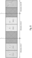
- Fig. 8 illustrates an embodiment for an enhanced discovery mechanism in accordance with embodiments of the present invention.
- the discovery circles 1 to M illustrated in Fig. 8 apply, and the UEs may be sorted according to the geographic locations.
- UEs having an RSSI above the threshold T1 are associated with a first discovery circle, while UEs with a RSSI between thresholds T1 and T2 are associated with a second discovery level, and so on.
- the discover circles mentioned above with reference to Fig. 8 represent a coverage area or communication range, and the number of circles may depend on the QoS and/or on the required communication range.
- the complied sorted list may be used for discovery enhancement mechanisms, for example to introduce proximity and distance based aware communications.
- the sorting of the UEs in accordance with the discovery list of Fig. 8 may be done based on the above-mentioned measurements on the sidelink, for example on the basis of power, RSSI, RSRP measurements, or it may be based on distance information obtained otherwise.
- the UE IDs may be the physical destination ID of the UEs for a unicast communication or the group ID for a groupcast communication. This information may be conveyed using the SCI.
- the discovery mechanism may refer to upper layers, for example using the L2 destination ID, or it may allocate a virtual ID for every discovered UE which may then be used for certain messages, like safety messages and/or for broadcast only.
- the communication to the UEs in the discovery list may be adapted to the actual QoS and the actual communication range as defined, for example, by the circles mentioned above.
- the minimum required communication range it is noted that this may be the pre-configured communication range, the semi-flexible communication range or the flexible communication range mentioned above.
- the mapping in accordance with embodiments, may be between the minimum required communication range and one or more of certain QoS characteristics, like reliability, Block Error Rate, BLER, latency, E2E latency, priority, and the system or application QoS requirements.
- a communication range is determined as described above and is mapped to different MCS/TBS/power control levels which is, in turn, a map to different QoS flows.
- a QoS flow means packets are classified and marked using a QFI (QoS Flow Identifier).
- the 5G QoS flows are mapped in the AN (Access Network) to DRBs (Data Radio Bearers).
- DRBs Data Radio Bearers
- SLRBs Sidelink Radio Bearers
- table 1 illustrates a first mapping possibility for a QoS flow 1.
- Table 1 QoS 1 Range 1 (0 ⁇ L1 ⁇ Lmax1) 1- MCS1/TBS1/TPC1 ⁇ BLER 1 1- MCS2/TBS2/TPC2 ⁇ BLER 2 2- MCS3/TBS3/TPC3 ⁇ BLER 3
- Table 1 illustrates the flow QoS 1, which defines certain QoS requirements, BLER 1, BLER 2, BLER 3, for the system or an application or a service to be performed.
- the UE communicating with other UEs being in a range L1 that is between 0 and a maximum range, which is the minimum required range for the UE fulfils the BLER 1of QoS 1 when using MCS1/TBS1/TPC1, the BLER 2 of QoS 1 when using MCS2/TBS2/TPC2 and the BLER 3 of QoS 1 when using MCS3/TBS3/TPC3 as is indicated in the right-hand column of Table 1.
- the mapping may be between the QoS flows and one or more communication ranges which are mapped to one or more MCS/TBS/TPC parameters, as is illustrated in table 2 below.
- Table 2 Range 1 (0 ⁇ L1 ⁇ Lmax1) 1- MCS1/TBS1/TPC1 -- QoS 1 1- MCS2/TBS2/TPC2 -- QoS 2 2- MCS3/TBS3/TPC3 -- QoS 3
- a UE communicating with other UEs over the sidelink which are within range L1 may achieve the QoSs 1, 2 or 3 when using MCS1/TBS1/TPC1, MCS2/TBS2/TPC2 and MCS3/TBS3/TPC3, respectively, as is indicated in the right-hand column of Table 2.
- the minimum required communication range may not be employed only for unicast or groupcast communications, but it may also be used for a broadcast communication over the sidelink. For a broadcast communication no measurements of any vehicles in the proximity may be available to other vehicles. However, to ensure that all vehicles within the defined minimum required communication range receive a notification on the sidelink from the transmitting UE, in accordance with embodiments, the defined minimum required communication range is mapped on a defined transmit power. In accordance with embodiments a basic mapping between each defined minimum required communication range and a predefined transmit power is suggested.
- this mapping may be further enhanced based, for example, on the RF conditions, like an interference or traffic load, based on environmental conditions, like weather or mountains in the vicinity of the transmitting UE, which may be derived, for example, from vehicular measurements and from channel state information.
- a driving direction may also be employed for improving the communication range.
- the driving direction may be available from CAM or DENM messages. For example, when considering vehicles, on the basis of a driving direction, notifications may only be provided for vehicles driving in parallel to the transmitting vehicle or vehicles driving in the same direction.
- the vehicles or vehicular UEs may be assumed to have several antennas or antenna ports mounted by a vehicle, and in case a directional communication range is employed, the appropriate antenna/antenna port and, if supported, beamforming may also be employed to enhance the required communication range.
- the circles described above may be modified so as to extend more in a driving direction of the vehicles, i.e., they become more elliptic, as less communication range may be needed in the direction traverse to the traveling direction due to the limited widths of the street on which the vehicles may travel while longer communication ranges may be needed along the street.
- an accuracy with which the above-described minimum required communication range is determined may be enhanced. More specifically, the above-described semi-flexible communication range and the flexible communication range may be determined with an enhance accuracy.
- the just-mentioned approaches for determining the communication range in a semi-flexible way or in a flexible way may give a rough estimate of the distance between the transmitting UE and the receiving UE.
- GNSS information and a Roundtrip Time of Flight, RTF are employed to increase the accuracy of the distance between the receiving UE and the transmitting UE.
- neighboring vehicles may be provided with active reflectors, similar as in the secondary radar principle.
- the receiving UE may respond with a fixed time offset, which allows the determination of the RTF on the basis of which the distance between the transmitting UE and the receiving UE may be determined.
- the receiving UE includes its GPS coordinates. Based on the RTF and the coordinates the transmitting UE may more accurately determine the actual distance between the transmitting UE and the receiving UE. In accordance with embodiments, this may be extended to multiple receiving UEs that respond with a fixed time offset along with their respective GPS coordinates.
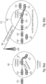
- Fig. 9 illustrates an embodiment not according to the claimed invention for enhancing the accuracy of the minimum required communication range as determined in accordance with the semi-flexible or flexible approach as described above.
- Fig. 9 illustrates a transmitting UE as well as respective receiving UEs RxUE1 to Rx UE n .
- the Tx UE broadcasts the request, as indicated at 420 to all Rx UEs, however, in accordance with other embodiments, the request may be transmitted also using a unicast communication to a dedicated one of the Rx UEs or using a groupcast communication for transmitting the request 420 to a number of Rx UEs forming groups.
- each a Rx UE Responsive to the request, each a Rx UE returns a message 422, to 422 n including the time at which the request 420 is received and the offset required at the Rx UE to process the request 420 and to transmit the response 422, so that on the basis of this information, the distance from Tx UE to the respective Rx UE may be calculated.
- the GPS coordinates also may be included in the response 422 as mentioned above.
- the Tx UE may average out GPS errors from all receiving UEs and of the transmitting UE itself, as is indicated in the lower part of Fig. 9 at 424.
- Accurate_Location P req 1 + ⁇ P offset 1 + GPS 1 1 + P req 2 + ⁇ P offset 2 + GPS 2 2 + ⁇ ... ... ... + P reqN + ⁇ P offsetN + GPS N N + GPS own N where in the equation above, the variables are as follows:
- the request 420 may be sent periodically, a periodically or totally randomly.
- the time offset may be included or transmitted using the control channel of the sidelink in a second stage of the SCI, or in case only a single stage SCI is used, it may be transmitted using the normal SCI format. In accordance with other embodiments, rather than transmitting the time offset information in the control channel, it may also be included in any of the other defined sidelink channels.
- the GPS coordinates may be included in a CAM message or a DENM message or for a message defined specifically for groupcast or unicast communications.
- the accuracy of the determination of the minimum required communication range may be further enhanced by more accurately determining the location of a transmitting UE.
- the location of the transmitting UE may be determined by a triangulation on the basis of signals transmitted from one or more stationary network entities in the vicinity of the transmitting UE, for example from a roadside unit or a base station or from any static UE location.
- Fig. 10 illustrates an embodiment of improving the determination of a location of a transmitting UE using triangulation.
- the transmitting Tx UE in the example of Fig.
- the first roadside unit 426a may be a traffic light provided at an elevated location at the center of the intersection, while the other two roadside units 426b, 426c may be respective street lamps.
- the Tx UE may calculate its location by triangulation and, based on this more accurate location also the distance to the receiving UEs may be determined more accurately thereby enhancing the accuracy with which it may be determined whether a certain UE is within or outside a minimum required communication range.
- the minimum required communication range is associated with the use of a feedback mechanism during the communication.
- a feedback mechanism during the communication.
- Limiting the number of receiving UEs allowed to send a feedback is advantageous as it increases the reliability as the retransmission is directed to the correct one of the receiving UEs or to the correct group of receiving UEs.
- Another advantage of limiting the number of receiving UEs allowed to send feedback is that this limits the number of retransmission requests at the transmitting UE which may improve the network performance and avoid congestions.
- a feedback mechanism like a HARQ feedback is used at least for groupcast and unicast communications in V2X communications.
- UEs making use of the flexible communication range approach described above in more detail may set up thresholds responsive to which the feedback is triggered, and the thresholds may be pre-configured or may be set up by the network. For example, in case a threshold for the feedback is exceeded, like an RSRP measurement for certain group members or a unicast member, the feedback may be initiated.
- an accurate distance between the transmitting UE and the receiving UEs is to be calculated, and dependent on the distance, it may be judged whether the UE is actually within the pre-configured minimum required communication range, the semi-flexible communication range or the flexible communication range which have been described in detail above.
- the feedback mechanism is deactivated or not initialized, i.e., the UE is not to send any retransmission requests (in case the UE is a receiving UE), or any retransmissions (in case the UE is a transmitting UE).
- the receiving UEs are allowed to send feedback, for example a HARQ feedback, so as to increase the reliability of the transmission.
- the transmitting UE uses a flexible communication range approach as described above and may set up thresholds that may be pre-configured or defined by the network, for triggering the feedback transmissions. If the threshold for the feedback is exceeded, for example if the RSRPs of the UEs of a certain group or a unicast UE is exceeded, a feedback is activated or initiated. In accordance with the present invention, the feedback is explicitly signaled, e.g., in a control channel.
- a transmitting UE determines certain UEs that are within the minimum required communication range and may signal, using for example the sidelink control channel, to those UEs that they are to activate their feedback mechanism so as to send ACK/NACK in response to a transmission so as to allow the transmitting UE to make a retransmissions within a useful time frame, i.e., within a timeframe during which the retransmission may be processed by the receiving UE while still providing, for example, sufficient time for the vehicular UE to react to the fully decoded message, like an emergency message to avoid, for example, a crash situation.
- a UE may have multiple destination L2 IDs and/or multiple source L2 IDs depending on different transmission/receptions, e.g. unicast, groupcast and multicast.
- Embodiments of the present invention have been described in detail above with reference to a sidelink communication using the PC5 interface.
- the present invention is not limited to the use of the PC5 interface. Any other interface allowing for a direct communication among one or more UEs may be employed, e.g., interfaces according to the IEEE 802.11p standard, the IEEE 802.15.4 standard (Zigbee), and others.
- a base station e.g., the connected mode, also referred to as NR mode 1 or LTE mode 3 configuration
- vehicles being in a mode in which when no SL resource allocation configuration or assistance is provided by a base station, e.g., the idle mode, also referred to as NR mode 2 or LTE mode 4 configuration.
- the present invention is not limited to V2V communications or V2X communications, rather it is also applicable to any device-to-device communications, for example non-vehicular mobile users or stationary users that perform a sidelink communication, e.g., over the PC5 interface. Also, in such scenarios, the inventive aspects described above may be employed.
Landscapes
- Engineering & Computer Science (AREA)
- Computer Networks & Wireless Communication (AREA)
- Signal Processing (AREA)
- Quality & Reliability (AREA)
- Mobile Radio Communication Systems (AREA)
Claims (8)
- Nutzergerät, UE, (3021) für ein Drahtloskommunikationssystem, wobeidas UE (3021) dazu konfiguriert ist, mit zumindest einem weiteren UE (302n) über einen Sidelink (304c) für eine Sidelink-Kommunikation mit dem weiteren UE (302n) verbunden zu sein, undzum Übertragen an das weitere UE (302n) über den Sidelink (304c) das UE (3021) dazu konfiguriert ist,Entfernungsinformationen zu erhalten, die einen bestimmten Kommunikationsbereich oder eine bestimmte Entfernung um das UE (3021) herum darstellen,einen HARQ-Rückmeldungsmechanismus für die Sidelink-Kommunikation zu initiieren, wenn sich das weitere UE (302n) an oder innerhalb des bestimmten Kommunikationsbereichs oder der bestimmten Entfernung befindet,den HARQ-Rückmeldungsmechanismus für die Sidelink-Kommunikation nicht zu initiieren, wenn sich das weitere UE (302n) außerhalb des bestimmten Kommunikationsbereichs oder der bestimmten Entfernung befindet, und wenn bestimmt wird, dass sich das weitere UE (302n) innerhalb des minimal erforderlichen Kommunikationsbereichs befindet, dem weiteren UE (302n) explizit zu signalisieren, den HARQ- Rückmeldungsmechanismus zu aktivieren, um die HARQ-Rückmeldung zu senden, als Reaktion auf eine Sidelink-Übertragung durch das UE (3021).
- Nutzergerät, UE, (3021) gemäß Anspruch 1, bei dem das UE (3021) dem weiteren UE (302n) über einen Steuerkanal explizit eine Aktivierung des HARQ-Rückmeldungsmechanismus signalisieren soll.
- Nutzergerät, UE, gemäß einem der vorhergehenden Ansprüche, bei dem das UE (3021, 302n) ein mobiles Endgerät, ein stationäres Endgerät, ein zellulares IoT-UE, ein Fahrzeug-UE, ein IoT- oder Schmalband-loT-, NB-loT-, Gerät, ein bodengestütztes Fahrzeug, ein Luftfahrzeug, eine Drohne, eine sich bewegende Basisstation, eine straßenseitige Einheit, ein Gebäude und/oder ein anderes Element oder Gerät umfasst, das mit einer Netzwerkkonnektivität versehen ist, die es dem Element/Gerät ermöglicht, unter Verwendung des Drahtloskommunikationsnetzwerks zu kommunizieren.
- Drahtloskommunikationssystem, das folgende Merkmale aufweist:eine oder mehr Basisstationen undeine Mehrzahl von Nutzergeräten, UEs, wobei zumindest einige der UEs ein UE (3021) gemäß einem der vorhergehenden Ansprüche aufweisen.
- Drahtloskommunikationssystem gemäß Anspruch 4, bei dem die Basisstation eine Makrozellenbasisstation, eine Kleinzellenbasisstation, eine zentrale Einheit einer Basisstation, eine verteilte Einheit einer Basisstation, eine straßenseitige Einheit, ein UE, einen abgesetzten Funkkopf, eine AMF, eine SMF, eine Kernnetzwerkentität, eine Netzwerkscheibe wie im NR- oder 5G-Kernkontext, einen Sende-/Empfangspunkt, TRP, aufweist, der es einem Element oder einem Gerät ermöglicht, unter Verwendung des Drahtloskommunikationsnetzwerks zu kommunizieren, wobei das Element oder das Gerät mit einer Netzwerkkonnektivität versehen ist, um unter Verwendung des Drahtloskommunikationsnetzwerks zu kommunizieren.
- Verfahren zum Betreiben eines Nutzergeräts, UE, (3021) für ein Drahtloskommunikationssystem, wobei das UE (3021) mit zumindest einem weiteren UE (302n) über einen Sidelink (304c) für eine Sidelink-Kommunikation mit dem weiteren UE (302n) verbunden ist,
wobei zum Übertragen an das weitere UE (302n) über den Sidelink das Verfahren folgende Schritte aufweist:Erhalten von Entfernungsinformationen, die einen bestimmten Kommunikationsbereich oder eine bestimmte Entfernung um das UE (3021) herum darstellen, Initiieren eines HARQ-Rückmeldungsmechanismus für die Sidelink-Kommunikation, wenn sich das weitere UE (302n) an oder innerhalb des bestimmten Kommunikationsbereichs oder der bestimmten Entfernung befindet,Nicht-Initiieren des HARQ-Rückmeldungsmechanismus für die Sidelink-Kommunikation, wenn sich das weitere UE (302n) außerhalb des bestimmten Kommunikationsbereichs oder der bestimmten Entfernung befindet, undwenn bestimmt wird, dass sich das weitere UE (302n) innerhalb des minimal erforderlichen Kommunikationsbereichs befindet, explizites Signalisieren an das weitere UE (302n), den HARQ-Rückmeldungsmechanismus zu aktivieren, um die HARQ-Rückmeldung zu senden, als Reaktion auf eine Übertragung durch das UE (3021). - Verfahren gemäß Anspruch 6, das ein explizites Signalisieren einer Aktivierung des HARQ-Rückmeldungsmechanismus über einen Steuerkanal an das weitere UE (302n) aufweist.
- Nichtflüchtiges Computerprogrammprodukt, das ein computerlesbares Medium aufweist, das Befehle speichert, die, wenn sie auf einem Computer ausgeführt werden, das Verfahren gemäß Anspruch 6 oder 7 durchführen.
Applications Claiming Priority (2)
| Application Number | Priority Date | Filing Date | Title |
|---|---|---|---|
| EP18203882 | 2018-10-31 | ||
| PCT/EP2019/072399 WO2020088817A1 (en) | 2018-10-31 | 2019-08-21 | Proximity awareness in sidelink communications |
Publications (2)
| Publication Number | Publication Date |
|---|---|
| EP3874776A1 EP3874776A1 (de) | 2021-09-08 |
| EP3874776B1 true EP3874776B1 (de) | 2025-01-29 |
Family
ID=64308479
Family Applications (1)
| Application Number | Title | Priority Date | Filing Date |
|---|---|---|---|
| EP19755399.3A Active EP3874776B1 (de) | 2018-10-31 | 2019-08-21 | Proximitätsbewusstsein in der sidelink-kommunikation |
Country Status (5)
| Country | Link |
|---|---|
| US (1) | US12483857B2 (de) |
| EP (1) | EP3874776B1 (de) |
| CN (1) | CN113261312A (de) |
| ES (1) | ES3023164T3 (de) |
| WO (1) | WO2020088817A1 (de) |
Families Citing this family (26)
| Publication number | Priority date | Publication date | Assignee | Title |
|---|---|---|---|---|
| EP3700108B1 (de) * | 2019-02-20 | 2023-08-09 | Volkswagen Aktiengesellschaft | Verfahren zum unterstützen einer ersten mobilstation zum vorhersagen der kanalqualität für eine geplante dezentrale drahtlose kommunikation zu einer kommunikationspartnerstation und mobilstation |
| US12058663B2 (en) * | 2018-09-19 | 2024-08-06 | Telefonaktiebolaget Lm Ericsson (Publ) | Methods providing resource selection for directional sidelink communications |
| CN119136318A (zh) * | 2019-01-11 | 2024-12-13 | 华为技术有限公司 | 一种数据传输方法及对应的终端 |
| US11206641B2 (en) * | 2019-03-29 | 2021-12-21 | Qualcomm Incorporated | Techniques for managing feedback in sidelink communications |
| CN115412216B (zh) * | 2019-05-02 | 2024-03-19 | Oppo广东移动通信有限公司 | 数据传输方法及装置 |
| US11206640B2 (en) | 2019-05-22 | 2021-12-21 | At&T Intellectual Property I, L.P. | Private local network access, authentication, and association for 5G or other next generation network |
| US11589417B2 (en) * | 2019-07-17 | 2023-02-21 | Intel Corporation | Sidelink communication range signaling |
| WO2020113241A2 (en) * | 2019-07-25 | 2020-06-04 | Futurewei Technologies, Inc. | Transmission beam control in wireless communication systems |
| US11229002B2 (en) * | 2019-09-05 | 2022-01-18 | Apple Inc. | Ranging with a mobile cellular device |
| WO2021087691A1 (zh) * | 2019-11-04 | 2021-05-14 | Oppo广东移动通信有限公司 | 功率控制方法、传输资源的确定方法、装置、终端及介质 |
| CN114616842B (zh) * | 2019-11-07 | 2026-03-31 | 索尼集团公司 | 无线通信设备和无线通信方法 |
| WO2021193374A1 (ja) * | 2020-03-26 | 2021-09-30 | ソニーセミコンダクタソリューションズ株式会社 | 通信装置および通信システム |
| US20230163888A1 (en) * | 2020-05-21 | 2023-05-25 | Kyocera Corporation | Distance-based hybrid automatic repeat request (harq) location unavailable configuration for group sidelink communication |
| JP7516894B2 (ja) * | 2020-06-12 | 2024-07-17 | 株式会社アイシン | 物体検出装置 |
| CN115868182B (zh) * | 2020-07-15 | 2024-10-18 | 高通股份有限公司 | 实施经由无线传输共享的信息的射程可靠性 |
| EP4193682A1 (de) * | 2020-08-05 | 2023-06-14 | Fraunhofer-Gesellschaft zur Förderung der angewandten Forschung e.V. | Nr-sidelink-weiterleitung |
| US11496857B2 (en) * | 2020-12-03 | 2022-11-08 | Qualcomm Incorporated | Traversable distance based feedback report triggering |
| US11647408B2 (en) * | 2020-12-16 | 2023-05-09 | Qualcomm Incorporated | Techniques for dynamically updating a search space of a sidelink control channel |
| US12069538B2 (en) * | 2021-08-12 | 2024-08-20 | Qualcomm Incorporated | Techniques for managing wireless analytics in sidelink communications |
| US12279210B2 (en) * | 2021-11-18 | 2025-04-15 | Qualcomm Incorporated | Roadside unit message transmission management |
| WO2023126181A1 (en) * | 2021-12-30 | 2023-07-06 | Telefonaktiebolaget Lm Ericsson (Publ) | Determining ranges between respective wireless communication devices |
| US12408011B2 (en) * | 2022-05-19 | 2025-09-02 | Qualcomm Incorporated | Conditional vehicle to everything (V2X) sensor data sharing |
| EP4290273B1 (de) | 2022-06-10 | 2024-08-07 | Nokia Technologies Oy | Verfahren und vorrichtungen in bezug auf drahtlose kommunikation |
| DE102022210781A1 (de) * | 2022-10-13 | 2024-04-18 | Volkswagen Aktiengesellschaft | Einbindung eines Luftfahrzeugs in ein V2X-System |
| WO2024186159A1 (ko) * | 2023-03-08 | 2024-09-12 | 엘지전자 주식회사 | 무선 통신 시스템에서 통신을 수행하기 위한 방법 및 장치 |
| CN116723458A (zh) * | 2023-06-28 | 2023-09-08 | 重庆长安汽车股份有限公司 | 动作执行方法、距离确定方法、装置、设备及存储介质 |
Citations (1)
| Publication number | Priority date | Publication date | Assignee | Title |
|---|---|---|---|---|
| WO2017103662A1 (en) * | 2015-12-18 | 2017-06-22 | Bayerische Motoren Werke Ag | Method for transmitting a stream in a wireless network from a wireless communication device to a plurality of wireless communication devices with nack avoidance |
Family Cites Families (15)
| Publication number | Priority date | Publication date | Assignee | Title |
|---|---|---|---|---|
| US20140146794A1 (en) * | 2011-04-08 | 2014-05-29 | Nokia Corporation | Modification of Mobility Priority Based on speed of User Equipment and Priority for Cell Operation |
| TWI620459B (zh) | 2012-05-31 | 2018-04-01 | 內數位專利控股公司 | 在蜂巢式通訊系統中賦能直鏈通訊排程及控制方法 |
| CN105075158B (zh) * | 2013-03-20 | 2018-02-13 | Lg 电子株式会社 | 在无线通信系统中使用设备对设备通信发送和接收信号的方法及其设备 |
| CN104284436B (zh) * | 2013-07-04 | 2018-03-02 | 华为技术有限公司 | 确定ue通信模式的方法、基站及ue |
| CN104581836B (zh) * | 2013-10-29 | 2020-04-28 | 中兴通讯股份有限公司 | 一种提高lte系统抗测距仪干扰能力的方法及设备 |
| US10694496B2 (en) * | 2014-11-07 | 2020-06-23 | Samsung Electronics Co., Ltd. | Method and apparatus for transmitting group message to user equipment (UE) |
| WO2016144574A1 (en) * | 2015-03-06 | 2016-09-15 | Interdigital Patent Holdings, Inc. | Methods, apparatus and systems for link adaptation for device-to-device (d2d) unicast communications |
| CN107534482B (zh) * | 2015-05-15 | 2021-01-29 | 索尼公司 | 移动通信系统、通信终端和方法 |
| CN106303915B (zh) * | 2015-06-08 | 2021-05-28 | 索尼公司 | 无线通信设备和无线通信方法 |
| US10455443B2 (en) * | 2015-10-18 | 2019-10-22 | Lg Electronics Inc. | Method for transmitting a priority list reporting in a D2D communication system and device therefor |
| US11240783B2 (en) * | 2016-03-04 | 2022-02-01 | Lg Electronics Inc. | V2X transmission resource selecting method implemented by terminal in wireless communication system and terminal using same |
| EP3476069B1 (de) * | 2016-06-22 | 2020-05-06 | Telefonaktiebolaget LM Ericsson (publ) | Verfahren und vorrichtungen für gruppenübertragungen |
| EP3273634A1 (de) * | 2016-07-18 | 2018-01-24 | Panasonic Intellectual Property Corporation of America | Verbesserte unterstützung der dienstqualität für v2x-übertragungen |
| US11638129B2 (en) * | 2017-06-26 | 2023-04-25 | Lg Electronics Inc. | Method for operating terminal for V2X communication in wireless communication system and terminal using same method |
| WO2019197025A1 (en) * | 2018-04-11 | 2019-10-17 | Telefonaktiebolaget Lm Ericsson (Publ) | Technique for sidelink feedback transmissions |
-
2019
- 2019-08-21 EP EP19755399.3A patent/EP3874776B1/de active Active
- 2019-08-21 WO PCT/EP2019/072399 patent/WO2020088817A1/en not_active Ceased
- 2019-08-21 CN CN201980087503.8A patent/CN113261312A/zh active Pending
- 2019-08-21 ES ES19755399T patent/ES3023164T3/es active Active
-
2021
- 2021-04-26 US US17/240,722 patent/US12483857B2/en active Active
Patent Citations (1)
| Publication number | Priority date | Publication date | Assignee | Title |
|---|---|---|---|---|
| WO2017103662A1 (en) * | 2015-12-18 | 2017-06-22 | Bayerische Motoren Werke Ag | Method for transmitting a stream in a wireless network from a wireless communication device to a plurality of wireless communication devices with nack avoidance |
Also Published As
| Publication number | Publication date |
|---|---|
| WO2020088817A1 (en) | 2020-05-07 |
| US20210250118A1 (en) | 2021-08-12 |
| US12483857B2 (en) | 2025-11-25 |
| EP3874776A1 (de) | 2021-09-08 |
| ES3023164T3 (en) | 2025-05-30 |
| CN113261312A (zh) | 2021-08-13 |
Similar Documents
| Publication | Publication Date | Title |
|---|---|---|
| EP3874776B1 (de) | Proximitätsbewusstsein in der sidelink-kommunikation | |
| US11736974B2 (en) | Wireless device, radio network node and methods performed therein | |
| EP4060923A1 (de) | Vorkonfiguriertes prs-übertragungsverfahren für sidelink-positionierung und vorrichtung dafür | |
| EP3909163A2 (de) | Verbesserungen der zuverlässigkeit von nr v2x | |
| EP3841781B1 (de) | Verfahren und vorrichtung zur bestimmung des paketkommunikationsbereichs in einem endgerätedirektkommunikationssystem | |
| EP3915282B1 (de) | Durch ein benutzergerät durchgeführtes verfahren zur handhabung der kommunikation in einem drahtloskommunikationsnetzwerk | |
| EP3718362A1 (de) | Drahtlose vorrichtung, funknetzwerkknoten und darin ausgeführte verfahren zur handhabung der kommunikation zwischen drahtlosen vorrichtungen in einem drahtloskommunikationsnetz | |
| US12401462B2 (en) | Method for user equipment to transmit and receive feedback information in wireless communication system supporting sidelink and device for same | |
| CN112385250A (zh) | 用于交通工具通信的中继 | |
| EP3834541B1 (de) | Verfahren zur ressourcenzuteilung in einer vorrichtung-zu-vorrichtung-kommunikation | |
| EP4214983A1 (de) | Timing-aspekte für nr-sl-hilfsinformationsnachrichten | |
| US20240292454A1 (en) | Method for performing sidelink communication by terminal in wireless communication system and device therefor | |
| US20240259862A1 (en) | E2E QoS WITH SIDELINK RELAY | |
| KR20230008165A (ko) | 사이드링크를 지원하는 무선통신시스템에서 ue가 협력 통신을 수행하는 방법 및 이를 위한 장치 | |
| KR20240008869A (ko) | Sl drx를 위한 l1 및 l2 방법 | |
| US20250254741A1 (en) | U2u relay discovery and (re-)selection | |
| WO2022117819A1 (en) | Traffic based random resource selection on nr sidelink | |
| US12101701B2 (en) | Multi-static sensing network for assisting vehicle-to-everything (V2X) communication | |
| JP2024536164A (ja) | サイドリンクコリジョンインジケータのue手順 | |
| US20240080753A1 (en) | UE-A Determination in Inter-UE Coordination | |
| US20250227728A1 (en) | Sl ue relay enhancements |
Legal Events
| Date | Code | Title | Description |
|---|---|---|---|
| STAA | Information on the status of an ep patent application or granted ep patent |
Free format text: STATUS: UNKNOWN |
|
| STAA | Information on the status of an ep patent application or granted ep patent |
Free format text: STATUS: THE INTERNATIONAL PUBLICATION HAS BEEN MADE |
|
| PUAI | Public reference made under article 153(3) epc to a published international application that has entered the european phase |
Free format text: ORIGINAL CODE: 0009012 |
|
| STAA | Information on the status of an ep patent application or granted ep patent |
Free format text: STATUS: REQUEST FOR EXAMINATION WAS MADE |
|
| 17P | Request for examination filed |
Effective date: 20210427 |
|
| AK | Designated contracting states |
Kind code of ref document: A1 Designated state(s): AL AT BE BG CH CY CZ DE DK EE ES FI FR GB GR HR HU IE IS IT LI LT LU LV MC MK MT NL NO PL PT RO RS SE SI SK SM TR |
|
| DAV | Request for validation of the european patent (deleted) | ||
| DAX | Request for extension of the european patent (deleted) | ||
| RAP3 | Party data changed (applicant data changed or rights of an application transferred) |
Owner name: FRAUNHOFER-GESELLSCHAFT ZUR FOERDERUNG DER ANGEWANDTEN FORSCHUNG E.V. |
|
| STAA | Information on the status of an ep patent application or granted ep patent |
Free format text: STATUS: EXAMINATION IS IN PROGRESS |
|
| 17Q | First examination report despatched |
Effective date: 20230714 |
|
| REG | Reference to a national code |
Ref country code: DE Ref legal event code: R079 Free format text: PREVIOUS MAIN CLASS: H04W0004400000 Ipc: H04L0041501900 Ref country code: DE Ref legal event code: R079 Ref document number: 602019065402 Country of ref document: DE Free format text: PREVIOUS MAIN CLASS: H04W0004400000 Ipc: H04L0041501900 |
|
| GRAP | Despatch of communication of intention to grant a patent |
Free format text: ORIGINAL CODE: EPIDOSNIGR1 |
|
| STAA | Information on the status of an ep patent application or granted ep patent |
Free format text: STATUS: GRANT OF PATENT IS INTENDED |
|
| RIC1 | Information provided on ipc code assigned before grant |
Ipc: H04W 4/02 20180101ALI20240809BHEP Ipc: H04L 67/61 20220101ALI20240809BHEP Ipc: H04L 1/00 20060101ALI20240809BHEP Ipc: G08G 1/00 20060101ALI20240809BHEP Ipc: H04L 41/5019 20220101AFI20240809BHEP |
|
| INTG | Intention to grant announced |
Effective date: 20240904 |
|
| GRAS | Grant fee paid |
Free format text: ORIGINAL CODE: EPIDOSNIGR3 |
|
| GRAA | (expected) grant |
Free format text: ORIGINAL CODE: 0009210 |
|
| STAA | Information on the status of an ep patent application or granted ep patent |
Free format text: STATUS: THE PATENT HAS BEEN GRANTED |
|
| AK | Designated contracting states |
Kind code of ref document: B1 Designated state(s): AL AT BE BG CH CY CZ DE DK EE ES FI FR GB GR HR HU IE IS IT LI LT LU LV MC MK MT NL NO PL PT RO RS SE SI SK SM TR |
|
| REG | Reference to a national code |
Ref country code: GB Ref legal event code: FG4D |
|
| REG | Reference to a national code |
Ref country code: CH Ref legal event code: EP |
|
| REG | Reference to a national code |
Ref country code: DE Ref legal event code: R096 Ref document number: 602019065402 Country of ref document: DE |
|
| REG | Reference to a national code |
Ref country code: IE Ref legal event code: FG4D |
|
| P01 | Opt-out of the competence of the unified patent court (upc) registered |
Free format text: CASE NUMBER: APP_7856/2025 Effective date: 20250217 |
|
| REG | Reference to a national code |
Ref country code: NL Ref legal event code: FP |
|
| REG | Reference to a national code |
Ref country code: ES Ref legal event code: FG2A Ref document number: 3023164 Country of ref document: ES Kind code of ref document: T3 Effective date: 20250530 |
|
| PG25 | Lapsed in a contracting state [announced via postgrant information from national office to epo] |
Ref country code: RS Free format text: LAPSE BECAUSE OF FAILURE TO SUBMIT A TRANSLATION OF THE DESCRIPTION OR TO PAY THE FEE WITHIN THE PRESCRIBED TIME-LIMIT Effective date: 20250429 |
|
| PG25 | Lapsed in a contracting state [announced via postgrant information from national office to epo] |
Ref country code: FI Free format text: LAPSE BECAUSE OF FAILURE TO SUBMIT A TRANSLATION OF THE DESCRIPTION OR TO PAY THE FEE WITHIN THE PRESCRIBED TIME-LIMIT Effective date: 20250129 |
|
| PG25 | Lapsed in a contracting state [announced via postgrant information from national office to epo] |
Ref country code: PL Free format text: LAPSE BECAUSE OF FAILURE TO SUBMIT A TRANSLATION OF THE DESCRIPTION OR TO PAY THE FEE WITHIN THE PRESCRIBED TIME-LIMIT Effective date: 20250129 |
|
| REG | Reference to a national code |
Ref country code: LT Ref legal event code: MG9D |
|
| PG25 | Lapsed in a contracting state [announced via postgrant information from national office to epo] |
Ref country code: NO Free format text: LAPSE BECAUSE OF FAILURE TO SUBMIT A TRANSLATION OF THE DESCRIPTION OR TO PAY THE FEE WITHIN THE PRESCRIBED TIME-LIMIT Effective date: 20250429 Ref country code: IS Free format text: LAPSE BECAUSE OF FAILURE TO SUBMIT A TRANSLATION OF THE DESCRIPTION OR TO PAY THE FEE WITHIN THE PRESCRIBED TIME-LIMIT Effective date: 20250529 |
|
| REG | Reference to a national code |
Ref country code: AT Ref legal event code: MK05 Ref document number: 1764542 Country of ref document: AT Kind code of ref document: T Effective date: 20250129 |
|
| PG25 | Lapsed in a contracting state [announced via postgrant information from national office to epo] |
Ref country code: HR Free format text: LAPSE BECAUSE OF FAILURE TO SUBMIT A TRANSLATION OF THE DESCRIPTION OR TO PAY THE FEE WITHIN THE PRESCRIBED TIME-LIMIT Effective date: 20250129 |
|
| PG25 | Lapsed in a contracting state [announced via postgrant information from national office to epo] |
Ref country code: LV Free format text: LAPSE BECAUSE OF FAILURE TO SUBMIT A TRANSLATION OF THE DESCRIPTION OR TO PAY THE FEE WITHIN THE PRESCRIBED TIME-LIMIT Effective date: 20250129 Ref country code: PT Free format text: LAPSE BECAUSE OF FAILURE TO SUBMIT A TRANSLATION OF THE DESCRIPTION OR TO PAY THE FEE WITHIN THE PRESCRIBED TIME-LIMIT Effective date: 20250529 |
|
| PG25 | Lapsed in a contracting state [announced via postgrant information from national office to epo] |
Ref country code: GR Free format text: LAPSE BECAUSE OF FAILURE TO SUBMIT A TRANSLATION OF THE DESCRIPTION OR TO PAY THE FEE WITHIN THE PRESCRIBED TIME-LIMIT Effective date: 20250430 Ref country code: BG Free format text: LAPSE BECAUSE OF FAILURE TO SUBMIT A TRANSLATION OF THE DESCRIPTION OR TO PAY THE FEE WITHIN THE PRESCRIBED TIME-LIMIT Effective date: 20250129 |
|
| PG25 | Lapsed in a contracting state [announced via postgrant information from national office to epo] |
Ref country code: AT Free format text: LAPSE BECAUSE OF FAILURE TO SUBMIT A TRANSLATION OF THE DESCRIPTION OR TO PAY THE FEE WITHIN THE PRESCRIBED TIME-LIMIT Effective date: 20250129 |
|
| PG25 | Lapsed in a contracting state [announced via postgrant information from national office to epo] |
Ref country code: SE Free format text: LAPSE BECAUSE OF FAILURE TO SUBMIT A TRANSLATION OF THE DESCRIPTION OR TO PAY THE FEE WITHIN THE PRESCRIBED TIME-LIMIT Effective date: 20250129 |
|
| PGFP | Annual fee paid to national office [announced via postgrant information from national office to epo] |
Ref country code: NL Payment date: 20250826 Year of fee payment: 7 |
|
| PG25 | Lapsed in a contracting state [announced via postgrant information from national office to epo] |
Ref country code: SM Free format text: LAPSE BECAUSE OF FAILURE TO SUBMIT A TRANSLATION OF THE DESCRIPTION OR TO PAY THE FEE WITHIN THE PRESCRIBED TIME-LIMIT Effective date: 20250129 |
|
| PGFP | Annual fee paid to national office [announced via postgrant information from national office to epo] |
Ref country code: ES Payment date: 20250902 Year of fee payment: 7 |
|
| PG25 | Lapsed in a contracting state [announced via postgrant information from national office to epo] |
Ref country code: DK Free format text: LAPSE BECAUSE OF FAILURE TO SUBMIT A TRANSLATION OF THE DESCRIPTION OR TO PAY THE FEE WITHIN THE PRESCRIBED TIME-LIMIT Effective date: 20250129 |
|
| PGFP | Annual fee paid to national office [announced via postgrant information from national office to epo] |
Ref country code: DE Payment date: 20250604 Year of fee payment: 7 |
|
| PGFP | Annual fee paid to national office [announced via postgrant information from national office to epo] |
Ref country code: IT Payment date: 20250827 Year of fee payment: 7 |
|
| PGFP | Annual fee paid to national office [announced via postgrant information from national office to epo] |
Ref country code: GB Payment date: 20250827 Year of fee payment: 7 |
|
| PGFP | Annual fee paid to national office [announced via postgrant information from national office to epo] |
Ref country code: FR Payment date: 20250826 Year of fee payment: 7 |
|
| PG25 | Lapsed in a contracting state [announced via postgrant information from national office to epo] |
Ref country code: CZ Free format text: LAPSE BECAUSE OF FAILURE TO SUBMIT A TRANSLATION OF THE DESCRIPTION OR TO PAY THE FEE WITHIN THE PRESCRIBED TIME-LIMIT Effective date: 20250129 Ref country code: EE Free format text: LAPSE BECAUSE OF FAILURE TO SUBMIT A TRANSLATION OF THE DESCRIPTION OR TO PAY THE FEE WITHIN THE PRESCRIBED TIME-LIMIT Effective date: 20250129 |
|
| PG25 | Lapsed in a contracting state [announced via postgrant information from national office to epo] |
Ref country code: RO Free format text: LAPSE BECAUSE OF FAILURE TO SUBMIT A TRANSLATION OF THE DESCRIPTION OR TO PAY THE FEE WITHIN THE PRESCRIBED TIME-LIMIT Effective date: 20250129 |
|
| PG25 | Lapsed in a contracting state [announced via postgrant information from national office to epo] |
Ref country code: SK Free format text: LAPSE BECAUSE OF FAILURE TO SUBMIT A TRANSLATION OF THE DESCRIPTION OR TO PAY THE FEE WITHIN THE PRESCRIBED TIME-LIMIT Effective date: 20250129 |
|
| REG | Reference to a national code |
Ref country code: DE Ref legal event code: R097 Ref document number: 602019065402 Country of ref document: DE |
|
| PLBE | No opposition filed within time limit |
Free format text: ORIGINAL CODE: 0009261 |
|
| STAA | Information on the status of an ep patent application or granted ep patent |
Free format text: STATUS: NO OPPOSITION FILED WITHIN TIME LIMIT |
|
| REG | Reference to a national code |
Ref country code: CH Ref legal event code: L10 Free format text: ST27 STATUS EVENT CODE: U-0-0-L10-L00 (AS PROVIDED BY THE NATIONAL OFFICE) Effective date: 20251210 |
|
| 26N | No opposition filed |
Effective date: 20251030 |
|
| REG | Reference to a national code |
Ref country code: CH Ref legal event code: H13 Free format text: ST27 STATUS EVENT CODE: U-0-0-H10-H13 (AS PROVIDED BY THE NATIONAL OFFICE) Effective date: 20260324 |
|
| PG25 | Lapsed in a contracting state [announced via postgrant information from national office to epo] |
Ref country code: MC Free format text: LAPSE BECAUSE OF FAILURE TO SUBMIT A TRANSLATION OF THE DESCRIPTION OR TO PAY THE FEE WITHIN THE PRESCRIBED TIME-LIMIT Effective date: 20250129 |
|
| PG25 | Lapsed in a contracting state [announced via postgrant information from national office to epo] |
Ref country code: LU Free format text: LAPSE BECAUSE OF NON-PAYMENT OF DUE FEES Effective date: 20250821 |
|
| PG25 | Lapsed in a contracting state [announced via postgrant information from national office to epo] |
Ref country code: CH Free format text: LAPSE BECAUSE OF NON-PAYMENT OF DUE FEES Effective date: 20250831 |