EP3875014B1 - Roboterreiniger - Google Patents
Roboterreiniger Download PDFInfo
- Publication number
- EP3875014B1 EP3875014B1 EP21170404.4A EP21170404A EP3875014B1 EP 3875014 B1 EP3875014 B1 EP 3875014B1 EP 21170404 A EP21170404 A EP 21170404A EP 3875014 B1 EP3875014 B1 EP 3875014B1
- Authority
- EP
- European Patent Office
- Prior art keywords
- spin
- mop
- travel
- robot cleaner
- region
- Prior art date
- Legal status (The legal status is an assumption and is not a legal conclusion. Google has not performed a legal analysis and makes no representation as to the accuracy of the status listed.)
- Active
Links
Images






Classifications
-
- A—HUMAN NECESSITIES
- A47—FURNITURE; DOMESTIC ARTICLES OR APPLIANCES; COFFEE MILLS; SPICE MILLS; SUCTION CLEANERS IN GENERAL
- A47L—DOMESTIC WASHING OR CLEANING; SUCTION CLEANERS IN GENERAL
- A47L9/00—Details or accessories of suction cleaners, e.g. mechanical means for controlling the suction or for effecting pulsating action; Storing devices specially adapted to suction cleaners or parts thereof; Carrying-vehicles specially adapted for suction cleaners
- A47L9/28—Installation of the electric equipment, e.g. adaptation or attachment to the suction cleaner; Controlling suction cleaners by electric means
-
- A—HUMAN NECESSITIES
- A47—FURNITURE; DOMESTIC ARTICLES OR APPLIANCES; COFFEE MILLS; SPICE MILLS; SUCTION CLEANERS IN GENERAL
- A47L—DOMESTIC WASHING OR CLEANING; SUCTION CLEANERS IN GENERAL
- A47L11/00—Machines for cleaning floors, carpets, furniture, walls, or wall coverings
- A47L11/40—Parts or details of machines not provided for in groups A47L11/02 - A47L11/38, or not restricted to one of these groups, e.g. handles, arrangements of switches, skirts, buffers, levers
- A47L11/4011—Regulation of the cleaning machine by electric means; Control systems and remote control systems therefor
-
- A—HUMAN NECESSITIES
- A47—FURNITURE; DOMESTIC ARTICLES OR APPLIANCES; COFFEE MILLS; SPICE MILLS; SUCTION CLEANERS IN GENERAL
- A47L—DOMESTIC WASHING OR CLEANING; SUCTION CLEANERS IN GENERAL
- A47L11/00—Machines for cleaning floors, carpets, furniture, walls, or wall coverings
- A47L11/40—Parts or details of machines not provided for in groups A47L11/02 - A47L11/38, or not restricted to one of these groups, e.g. handles, arrangements of switches, skirts, buffers, levers
- A47L11/4061—Steering means; Means for avoiding obstacles; Details related to the place where the driver is accommodated
-
- A—HUMAN NECESSITIES
- A47—FURNITURE; DOMESTIC ARTICLES OR APPLIANCES; COFFEE MILLS; SPICE MILLS; SUCTION CLEANERS IN GENERAL
- A47L—DOMESTIC WASHING OR CLEANING; SUCTION CLEANERS IN GENERAL
- A47L11/00—Machines for cleaning floors, carpets, furniture, walls, or wall coverings
- A47L11/02—Floor surfacing or polishing machines
- A47L11/10—Floor surfacing or polishing machines motor-driven
- A47L11/14—Floor surfacing or polishing machines motor-driven with rotating tools
- A47L11/16—Floor surfacing or polishing machines motor-driven with rotating tools the tools being disc brushes
-
- A—HUMAN NECESSITIES
- A47—FURNITURE; DOMESTIC ARTICLES OR APPLIANCES; COFFEE MILLS; SPICE MILLS; SUCTION CLEANERS IN GENERAL
- A47L—DOMESTIC WASHING OR CLEANING; SUCTION CLEANERS IN GENERAL
- A47L11/00—Machines for cleaning floors, carpets, furniture, walls, or wall coverings
- A47L11/02—Floor surfacing or polishing machines
- A47L11/10—Floor surfacing or polishing machines motor-driven
- A47L11/14—Floor surfacing or polishing machines motor-driven with rotating tools
- A47L11/16—Floor surfacing or polishing machines motor-driven with rotating tools the tools being disc brushes
- A47L11/161—Floor surfacing or polishing machines motor-driven with rotating tools the tools being disc brushes with supply of cleaning agents
-
- A—HUMAN NECESSITIES
- A47—FURNITURE; DOMESTIC ARTICLES OR APPLIANCES; COFFEE MILLS; SPICE MILLS; SUCTION CLEANERS IN GENERAL
- A47L—DOMESTIC WASHING OR CLEANING; SUCTION CLEANERS IN GENERAL
- A47L11/00—Machines for cleaning floors, carpets, furniture, walls, or wall coverings
- A47L11/02—Floor surfacing or polishing machines
- A47L11/10—Floor surfacing or polishing machines motor-driven
- A47L11/14—Floor surfacing or polishing machines motor-driven with rotating tools
- A47L11/18—Floor surfacing or polishing machines motor-driven with rotating tools the tools being roll brushes
- A47L11/185—Floor surfacing or polishing machines motor-driven with rotating tools the tools being roll brushes with supply of cleaning agents
-
- A—HUMAN NECESSITIES
- A47—FURNITURE; DOMESTIC ARTICLES OR APPLIANCES; COFFEE MILLS; SPICE MILLS; SUCTION CLEANERS IN GENERAL
- A47L—DOMESTIC WASHING OR CLEANING; SUCTION CLEANERS IN GENERAL
- A47L11/00—Machines for cleaning floors, carpets, furniture, walls, or wall coverings
- A47L11/29—Floor-scrubbing machines characterised by means for taking-up dirty liquid
- A47L11/292—Floor-scrubbing machines characterised by means for taking-up dirty liquid having rotary tools
- A47L11/293—Floor-scrubbing machines characterised by means for taking-up dirty liquid having rotary tools the tools being disc brushes
-
- A—HUMAN NECESSITIES
- A47—FURNITURE; DOMESTIC ARTICLES OR APPLIANCES; COFFEE MILLS; SPICE MILLS; SUCTION CLEANERS IN GENERAL
- A47L—DOMESTIC WASHING OR CLEANING; SUCTION CLEANERS IN GENERAL
- A47L11/00—Machines for cleaning floors, carpets, furniture, walls, or wall coverings
- A47L11/29—Floor-scrubbing machines characterised by means for taking-up dirty liquid
- A47L11/30—Floor-scrubbing machines characterised by means for taking-up dirty liquid by suction
- A47L11/302—Floor-scrubbing machines characterised by means for taking-up dirty liquid by suction having rotary tools
- A47L11/305—Floor-scrubbing machines characterised by means for taking-up dirty liquid by suction having rotary tools the tools being disc brushes
-
- A—HUMAN NECESSITIES
- A47—FURNITURE; DOMESTIC ARTICLES OR APPLIANCES; COFFEE MILLS; SPICE MILLS; SUCTION CLEANERS IN GENERAL
- A47L—DOMESTIC WASHING OR CLEANING; SUCTION CLEANERS IN GENERAL
- A47L11/00—Machines for cleaning floors, carpets, furniture, walls, or wall coverings
- A47L11/40—Parts or details of machines not provided for in groups A47L11/02 - A47L11/38, or not restricted to one of these groups, e.g. handles, arrangements of switches, skirts, buffers, levers
- A47L11/4013—Contaminants collecting devices, i.e. hoppers, tanks or the like
-
- A—HUMAN NECESSITIES
- A47—FURNITURE; DOMESTIC ARTICLES OR APPLIANCES; COFFEE MILLS; SPICE MILLS; SUCTION CLEANERS IN GENERAL
- A47L—DOMESTIC WASHING OR CLEANING; SUCTION CLEANERS IN GENERAL
- A47L11/00—Machines for cleaning floors, carpets, furniture, walls, or wall coverings
- A47L11/40—Parts or details of machines not provided for in groups A47L11/02 - A47L11/38, or not restricted to one of these groups, e.g. handles, arrangements of switches, skirts, buffers, levers
- A47L11/4036—Parts or details of the surface treating tools
- A47L11/4038—Disk shaped surface treating tools
-
- A—HUMAN NECESSITIES
- A47—FURNITURE; DOMESTIC ARTICLES OR APPLIANCES; COFFEE MILLS; SPICE MILLS; SUCTION CLEANERS IN GENERAL
- A47L—DOMESTIC WASHING OR CLEANING; SUCTION CLEANERS IN GENERAL
- A47L11/00—Machines for cleaning floors, carpets, furniture, walls, or wall coverings
- A47L11/40—Parts or details of machines not provided for in groups A47L11/02 - A47L11/38, or not restricted to one of these groups, e.g. handles, arrangements of switches, skirts, buffers, levers
- A47L11/4036—Parts or details of the surface treating tools
- A47L11/4041—Roll shaped surface treating tools
-
- A—HUMAN NECESSITIES
- A47—FURNITURE; DOMESTIC ARTICLES OR APPLIANCES; COFFEE MILLS; SPICE MILLS; SUCTION CLEANERS IN GENERAL
- A47L—DOMESTIC WASHING OR CLEANING; SUCTION CLEANERS IN GENERAL
- A47L11/00—Machines for cleaning floors, carpets, furniture, walls, or wall coverings
- A47L11/40—Parts or details of machines not provided for in groups A47L11/02 - A47L11/38, or not restricted to one of these groups, e.g. handles, arrangements of switches, skirts, buffers, levers
- A47L11/4063—Driving means; Transmission means therefor
- A47L11/4066—Propulsion of the whole machine
-
- A—HUMAN NECESSITIES
- A47—FURNITURE; DOMESTIC ARTICLES OR APPLIANCES; COFFEE MILLS; SPICE MILLS; SUCTION CLEANERS IN GENERAL
- A47L—DOMESTIC WASHING OR CLEANING; SUCTION CLEANERS IN GENERAL
- A47L11/00—Machines for cleaning floors, carpets, furniture, walls, or wall coverings
- A47L11/40—Parts or details of machines not provided for in groups A47L11/02 - A47L11/38, or not restricted to one of these groups, e.g. handles, arrangements of switches, skirts, buffers, levers
- A47L11/408—Means for supplying cleaning or surface treating agents
- A47L11/4083—Liquid supply reservoirs; Preparation of the agents, e.g. mixing devices
-
- B—PERFORMING OPERATIONS; TRANSPORTING
- B25—HAND TOOLS; PORTABLE POWER-DRIVEN TOOLS; MANIPULATORS
- B25J—MANIPULATORS; CHAMBERS PROVIDED WITH MANIPULATION DEVICES
- B25J11/00—Manipulators not otherwise provided for
- B25J11/008—Manipulators for service tasks
- B25J11/0085—Cleaning
-
- A—HUMAN NECESSITIES
- A47—FURNITURE; DOMESTIC ARTICLES OR APPLIANCES; COFFEE MILLS; SPICE MILLS; SUCTION CLEANERS IN GENERAL
- A47L—DOMESTIC WASHING OR CLEANING; SUCTION CLEANERS IN GENERAL
- A47L2201/00—Robotic cleaning machines, i.e. with automatic control of the travelling movement or the cleaning operation
- A47L2201/04—Automatic control of the travelling movement; Automatic obstacle detection
Definitions
- the present disclosure relates to a robot cleaner capable of performing a mopping operation.
- a robot cleaner (also referred to as an autonomous cleaner) is an apparatus that autonomously travels and cleans a floor or other surface.
- the robot cleaner may suction foreign matter, such as dust, from the floor or may sweep away foreign matter on the floor while traveling autonomously.
- Another type of robot cleaners may clean by performing a mopping operation using a spin-mop.
- a robot cleaner including a spin-mop may also travel by using the rotation of the spin-mop when cleaning the floor.
- water may be supplied to the spin-mop when cleaning the floor.
- Korean Registered Patent Publication No. 10-1602790 describes a robot cleaner that travels using rotations of mops.
- This robot cleaner includes a pair of rotary members that have shafts that are coupled at one end to a pair of mops (or mop heads) that are positioned in a leftward-rightward direction.
- the shafts extend substantially vertically and are inclined in an outward direction to incline bottom surfaces of the mops.
- the rotary members are concurrently rotated on a floor surface while portions of the mops fixed to the rotary members are in contact with the floor surface to generate friction forces to move the robot cleaner.
- the respective frictional forces generated between each of the rotating mops and the floor may frequently change, such that the robot cleaner may have difficulty travelling in a straight path.
- the frictional forces may change, for example, due to differences in the moisture levels in the mops, differences in the material or texture of the floors, differences in amounts or types of foreign substances on the floor or the mops, etc. If the robot cleaner does not travel in a straight path, the robot cleaner cannot reliably move adjacent to a wall or other obstacle having a straight surface, such that the robot cleaner may miss a considerable portion of the floor near the wall and will not wipe this portion of the floor with the mops.
- Korean Registered Patent Publication No. 10-1578879 describes another robot cleaner that includes a main body, a driving unit provided in the main body to supply power to move the robot cleaner, first and second rotary members that are rotated, respectively, about first and second rotary shafts by power from the driving unit, and wet cleaners that are fixed to ends of the first and second rotary members.
- This robot cleaner sequentially rotates the first rotary member and the second rotary member such that the robot cleaner travels in an S-shaped pattern.
- the S-shaped moving pattern provides a travel speed and a cleaning speed that are generally slower in comparison to simultaneously rotating two rotary members to move the robot cleaner.
- the S-shaped moving patterns may limit an ability of the cleaner to perform certain kinds of motions.
- robot cleaners such as automated vacuum cleaners
- a robot cleaner that is driven through spin-mops may not clean in a central part of the robot cleaner between the spin mops.
- a robot cleaner that is driven through spin-mops may leave uncleaned regions even when the robot cleaner uses the conventional zigzag-pattern travel. Therefore, it is desirable to control a robot cleaner that performs a mopping operation to travel effectively while minimizing uncleaned regions.
- a robot cleaner comprises a first spin-mop and a second spin-mop that contact a floor while rotating in a clockwise direction or in a counterclockwise direction when viewed from above; and a controller that manages respective rotational directions and rotational speeds of the first spin-mop and the second spin-mop to move the robot cleaner such that: the robot cleaner travels in a zigzag pattern that includes a first travel during which the robot cleaner moves in a first direction, and a second travel during which the robot cleaner moves in a second direction which is opposite the first direction, and a first region of the floor over which one of the first spin-mop or the second spin-mop moves during the second travel overlaps a second region of the floor over which the first spin-mop moves during the first travel and a third region of the floor over which the second spin-mop moves during the first travel.
- the controller may be configured to selectively change the rotational directions and speeds of the first spin-mop and the second spin-mop to control a turning direction and a turning radius of the robot cleaner.
- An uncleaned region may be present between the second region of the floor over which the first spin-mop moves during the first travel and the third region of the floor over which the second spin-mop moves during the first travel.
- the first region of the floor over which the one of the first spin-mop or the second spin-mop moves during the second travel may pass over the uncleaned region.
- the controller may further be configured to manage the respective rotational directions and rotational speeds of the first spin-mop and the second spin-mop such that: the zigzag pattern includes a third travel during which the robot cleaner travels in the first direction after the second travel, and a fourth region of the floor over which the first spin-mop or the second spin-mop moves during the third travel overlaps the first region of the floor over which one of the first spin-mop or the second spin mop moves during the second travel and a fifth region of the floor over which another one of the first spin-mop or the second spin-mop moves during the second travel.
- the controller may further be configured to manage the respective rotational directions and rotational speeds of the first spin-mop and the second spin-mop such a region of the floor over which one of the first or second spin-mops moves during an (N+1)-th straight travel overlaps both regions of the floors over which the first spin-mop and the second spin-mop move during an N-th straight travel.
- the controller may further be configured to manage the respective rotational directions and rotational speeds of the first spin-mop and the second spin-mop such that the first travel and the second travel are repeatedly performed in sequence.
- the controller may further be configured to manage the respective rotational directions and rotational speeds of the first spin-mop and the second spin-mop such that: the zigzag pattern includes a fourth travel in which the robot cleaner travels in the first direction after the second travel, and a fourth region of the floor over which the first spin mop or the second spin-mop moves during the fourth travel overlaps one of the second region over which the first mop moves during the second travel or the third region over which the second spin-mop moves during the second travel.
- the controller may further be configured to manage the respective rotational directions and rotational speeds of the first spin-mop and the second spin-mop such that: the robot cleaner repeatedly performs a travel pattern in which an N-th straight travel, an (N+1)-th straight travel, an (N+2)-th straight travel, and an (N+3)-th straight travel are sequentially performed.
- a region of the floor over which one of the first or second spin-mops moves during the (N+1)-th straight travel may overlap both regions of the floor over which the first spin-mop and the second spin-mop move during the N-th straight travel.
- a region of the floor over which one of the first or second spin-mops moves during the (N+2)-th straight travel may overlap a region of the floor over which one of the first and second spin-mops moves during the (N+1)-th straight travel.
- a region of the floor over which one of the first or second spin-mops moves during the (N+3)-th straight travel may overlap both regions of the floor over which the first spin-mop and the second spin-mop move during the (N+2)-th straight travel.
- the controller may further be configured to manage the first spin-mop and the second spin-mop such that the first spin-mop and the second spin-mop are rotated in opposite directions at different speeds to turn the robot cleaner.
- the controller may further be configured to manage the first spin-mop and the second spin-mop such that the first spin-mop and the second spin-mop are rotated in a common rotational direction at different speeds to turn the robot cleaner.
- the robot cleaner may further comprise a water supply configured to supply water to the first spin-mop and the second spin-mop.
- the first spin-mop and the second spin-mop may be included in a first cleaning module.
- the robot cleaner may further comprise a second cleaning module spaced apart from the first spin-mop and the second spin-mop in a forward direction or a rearward direction.
- the second cleaning module may be configured to collect foreign matter from the floor.
- the second cleaning module may include sweeping rollers configured to rotate to contact the floor and introduce foreign matter on the floor into the second cleaning module.
- the first spin-mop and the second spin-mop may be inclined upward toward a center of the robot cleaner.
- a mop (or mop head), which will be mentioned below, may be made of various materials, such as fabric or paper.
- the mop may be washable for repeated use or may be disposable.
- the present disclosure may apply to a cleaner that is manually moved by a user or to a robot cleaner that travels autonomously.
- the following discussion describes an embodiment related to a robot cleaner.
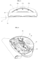
- FIG. 1 is a perspective view showing a robot cleaner according to an embodiment of the present disclosure
- FIG. 2 is a bottom perspective view of the robot cleaner according to the embodiment of the present disclosure
- FIG. 3 is a front view of the robot cleaner according to the embodiment of the present disclosure
- FIG. 4 is a view showing the internal construction of the robot cleaner according to the embodiment of the present disclosure.
- a robot cleaner according to the embodiment of the present disclosure includes a main body 20 that defines the external appearance of the robot cleaner.
- the robot cleaner includes a first cleaning module 40 that supports the main body 20.
- the robot cleaner may also include a second cleaning module 50 that supports the main body 20.
- the main body 20 may be supported by the first cleaning module 40 and the second cleaning module 50.
- the first cleaning module 40 may be referred to as a mop module 40 or a spin-mop module 40 that mop a floor or other surface to be cleaned when mop module 40 is in contact with the floor.
- the second cleaning module 50 may be referred to as a collection module 50 that collects foreign matter from the floor.
- the first cleaning module 40 may be configured to mop the floor when in contact with the floor.
- the first cleaning module 40 includes a left spin-mop 41a and a right spin-mop 41b configured to mop the floor while rotating in the clockwise direction or in the counterclockwise direction when viewed from above.
- the left spin-mop 41a and the right spin-mop 41b are configured to contact the floor.
- the first cleaning module 40 is positioned under the main body 20.
- the first cleaning module 40 may be positioned at the rear of the second cleaning module 50.
- the robot cleaner may be configured such that the main body 20 is movable according to the rotation of the first cleaning module 40 without any additional wheels or other movement device.
- the left spin-mop 41a and the right spin-mop 41b are configured to rotate about rotary shafts that extend substantially vertically in the upward-downward direction.
- the rotational direction or speed of the spin-mops 40 may be changed to control the travel of the robot cleaner.
- the robot cleaner may include the first cleaning module 40 with a pair of spin-mops 41a, 41b to move the main body 20 and a driving motor 38 for driving the spin-mops 41a, 41b.
- the robot cleaner according to this embodiment may further include a water tank 32 positioned inside the main body 20 to store water, a pump 34 that supplies the water from the water tank 32 to the first cleaning module 40, and a connection hose 36 for interconnecting the pump 34 and the water tank 32 or interconnecting the water tank 32 and the first cleaning module 40.
- the first cleaning module 40 is configured to mop the floor in a wet state using the water in the water tank 32.
- the spin-mops 41a and 41b may be configured to mop the floor when in contact with the floor.
- the robot cleaner according to this embodiment may further include the second cleaning module 50 that is positioned in front of the first cleaning module 40 to remove foreign matter from the floor before mopping the floor using the spin-mops 40.
- the second cleaning module 50 may be positioned behind the first cleaning module 40
- the second cleaning module 50 is spaced apart from the first cleaning module 40 in the forward-rearward direction to collect foreign matter from the floor in the state of being in contact with the floor.
- the second cleaning module 50 may include at least one collection unit (or collection bin) that defines a collection space to receive and store the collected foreign matter.
- the at least one collection unit may include a pair of collection units.
- the second cleaning module 50 may include sweeping units (or sweeping rollers) 51a and 51b configured to rotate in the state of being in contact with the floor such that foreign matter on the floor is introduced into the collection space.
- the sweeping units 51a and 51b are configured to rotate about a rotary shaft that extends in substantially the horizontal direction.
- the sweeping units 51a and 51b may include blades or brushes positioned in front of the collection units so as to directly contact the floor.
- the blades of the sweeping units 51a and 51b are configured to sweep the floor such that relatively bulky foreign matter is collected in the collection units.
- the second cleaning module 50 may be configured to mop the floor while sliding on the floor according to the movement of the main body 20. In another example, the second cleaning module 50 may be configured to mop the floor while rotating.
- the second cleaning module 50 may include a rotating mop that rotates along a rotation axis that extends in a right-left direction.
- the second cleaning module 50 may be configured to perform vacuum cleaning. The following description described the second cleaning module 50 as being configured to perform vacuum cleaning. However, it should be appreciated that type of the detailed construction of the second cleaning module 50 may be changed.
- the robot cleaner is configured such that the main body 20 is moved according to the rotation of at least one of the first and second cleaning modules 40 and 50 without any additional driving wheels.
- the main body 20 may be moved according to the rotation of the first cleaning module 40 alone.
- the robot cleaner may be configured such that the main body 20 is movable according to the rotation of the spin-mops 41a and 41b without any additional driving wheels.
- the second cleaning module 50 may include an auxiliary wheel 58 configured to contact the floor.
- the auxiliary wheel may be passive and may not be driven to rotate to move the robot cleaner.
- the auxiliary wheel 58 stabilize the body 20 to help the robot cleaner move smoothly in the forward-rearward direction, and to prevent the robot cleaner from overturning in the forward-rearward direction.
- the auxiliary wheel 58 may position the sweeping units 51a and 51b at a certain distance from to the floor such that the sweeping unit 51a and 51b efficiently sweeps the floor.
- the auxiliary wheel 58 may include a pair of auxiliary wheels 58a and 58b positioned at left and right sides of the robot cleaner.
- the left auxiliary wheel 58a is positioned at the left side of the left sweeping unit 51a.
- the right auxiliary wheel 58b is positioned at the right side of the right sweeping unit 51b.
- the auxiliary wheels 58a and 58b are positioned in a symmetrical arrangement.
- a middle auxiliary wheel 58m may be provided.
- the middle auxiliary wheel 58m is positioned between the collection units.
- the middle auxiliary wheel 58m may be spaced apart from the auxiliary wheels 58a and 58b in the forward-rearward direction.
- the robot cleaner may include an obstacle sensor 21 for sensing an obstacle in front of the robot cleaner.
- the main body 20 may be provided with a plurality of obstacle sensors 21a, 21b, 21c, 21d, and 21e.
- the obstacle sensor 21 may include front obstacle sensors 21a, 21b, and 21c that detect attributes of an obstacle in front of the robot cleaner and left and right obstacle sensors 21d and 21e for sensing obstacles at left and right sides of the robot cleaner.
- the robot cleaner may include a cliff sensor 23 for sensing if there is a cliff in the floor.
- the cliff sensor 23 may include a plurality of cliff sensors 23a and 23b.
- the second cleaning module 50 may be provided at the lower side thereof with cliff sensors 23a and 23b to sense if there is a cliff in the floor.
- the second cleaning module 50 may be provided at the rear thereof with a cliff sensor (not shown) that sense if there is a cliff in the floor.
- the cliff sensors 23a and 23b sense if there is a cliff in a region ahead of the first cleaning module 40.
- the robot cleaner may include a camera 25 to capture an external image.
- the camera 25 may be positioned at the top of the main body 20 to acquire an image of the external environment above the main body 20.
- the robot cleaner may perform a location recognition operation and a simultaneous localization and mapping (SLAM) operation using the image acquired by the camera 25.
- SLAM simultaneous localization and mapping
- the robot cleaner may be configured such that the spin-mops 41a and 41b are inclined at a predetermined angle ⁇ from the floor.
- the entire surfaces of the spin-mops 41a and 41b may not uniformly contact the floor, but the spin-mops 41a and 41b may be inclined at the predetermined angle ⁇ such that only the portions of the surfaces of the spin-mops 41a and 41b contact the floor.
- the spin-mops 41a and 41b may be positioned such that a frictional force is highest between the portions of the surfaces of the spin-mops 41a and 41b and the floor even when the entire surfaces of the spin-mops 41a and 41b contact the floor.
- the lower surface of the left spin-mop 41a and the lower surface of the right spin-mop 41b may be inclined.
- the lower surface of the left spin-mop 41a is generally inclined downward in the leftward direction
- the lower surface of the right spin-mop 41b is generally inclined downward in the rightward direction. That is, the left spin-mop 41a and the right spin-mop 41b may be inclined upward toward the center of the robot cleaner.
- the angle of inclination of the left spin-mop 41a and the angle of inclination of the right spin-mop 41b are acute angles.
- the angle of inclination may be set to be sufficiently small for the entire lower surfaces of the left spin-mop 41a and the right spin-mop 41b to contact the floor according to the rotation of the left spin-mop 41a and the right spin-mop 41b while the frictional force between the portions of the surfaces of the spin-mops 41a and 41b and the floor is the highest.
- the lower surface of the left spin-mop 41a is the lowest at the left side thereof, and the lower surface of the left spin-mop 41a is the highest at the right side thereof.
- the lower surface of the right spin-mop 41b is the lowest at the right side thereof, and the lower surface of the right spin-mop 41b is the highest at the left side thereof.
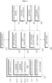
- FIG. 5 is a block diagram showing the control relationship between main components of the robot cleaner according to the embodiment of the present disclosure.
- a first cleaning module 520 and a second cleaning module 530 shown in FIG. 5 may correspond to the first cleaning module 40 and a second cleaning module 50, described with reference to FIGS. 1 to 4 .
- the robot cleaner may include a first cleaning module 520 including a left spin-mop 41a and a right spin-mop 41b configured to contact the floor while rotating in the clockwise direction or in the counterclockwise direction when viewed from above, a second cleaning module 530 including sweeping units 51a and 51b configured to contact the floor while rotating in the clockwise direction or in the counterclockwise direction when viewed from the left side, the second cleaning module 530 being spaced apart from the left spin-mop 41a and the right spin-mop 41b in the forward-rearward direction, and a controller 550 for controlling the overall operation of the robot cleaner.
- a first cleaning module 520 including a left spin-mop 41a and a right spin-mop 41b configured to contact the floor while rotating in the clockwise direction or in the counterclockwise direction when viewed from above
- a second cleaning module 530 including sweeping units 51a and 51b configured to contact the floor while rotating in the clockwise direction or in the counterclockwise direction when viewed from the
- the controller 550 may perform control such that, when the robot cleaner travels in a zigzag pattern including a first travel, during which the robot cleaner travels straight in a first direction, and a second travel, during which the robot cleaner travels straight in a second direction, which is opposite the first direction, the movement trajectory of the left spin-mop 41a or the right spin-mop 41b during the second travel overlaps the movement trajectory of the left spin-mop 41a and the movement trajectory of the right spin-mop 41b during the first travel.
- the movement trajectory of the left spin-mop 41a and the movement trajectory of the right spin-mop 41b may refer to regions of the floor over which the left spin-mop 41a and the right spin-mop 41b move while contacting the floor.
- the movement trajectory of the left spin-mop 41a and the movement trajectory of the right spin-mop 41b may refer to a set of regions of the floor over which the left spin-mop 41a and the right spin-mop 41b move while contacting the floor with a predetermined magnitude of frictional force.
- the robot cleaner may further include a water supply module (or water supply) 540 for supplying water to the left spin-mop 41a and the right spin-mop 41b.
- the water supply module 540 may include a water tank 32 positioned inside the main body 20 for storing water, a pump 34 for supplying the water from the water tank 32 to the first cleaning module 40, and a connection hose 36 for interconnecting the pump 34 and the water tank 32 or interconnecting the water tank 32 and the first cleaning module 40.
- the robot cleaner according to the embodiment of the present disclosure may travel according to the rotation of the spin-mops 41a and 41b.
- the robot cleaner according to the embodiment of the present disclosure may travel through front wheels formed in the shape of the sweeping units 51a and 51b and rear wheels formed in the shape of the spin-mops 41a and 41b.
- the spin-mops 41a and 41b perform wet cleaning using the received water, and at the same time may generate driving force for travel in a desired direction.
- the controller 550 may control the rotation of the left spin-mop 41a and the right spin-mop 41b and the rotation of the sweeping units 51a and 51b. In addition, the controller 550 may independently control the spin-mops 41a and 41b and the sweeping units 51a and 51b.
- the robot cleaner may perform various travel motions and simultaneously perform both wet and dry cleaning operations based on controlling the rotation directions and speeds of the spin-mops 41a and 41b and the sweeping units 51a and 51b.
- the controller 550 may control the travel of the robot cleaner by generating motion based on the difference between drag forces caused by the difference in the number of rotations and the frictional forces of the spin-mops 41a and 41b.
- the controller 550 may control the travel of the robot cleaner by generating motion based on the difference between drag forces in the state in which the spin-mops 41a and 41b and the sweeping units 51a and 51b slide simultaneously or based on the difference between drag forces caused by the difference between the number of rotations and the frictional forces of the spin-mops 41a and 41b and the sweeping units 51a and 51b.
- the first cleaning module 520 may include a motor 38 to rotate the spin-mops 41a and 41b.
- the motor 38 may include a left motor to rotate the left spin-mop 41a and a right motor to rotate the right spin-mop 41b.
- the controller 550 may include a first motor-driving unit (or first motor circuitry) 551 to drive the motor 38 for rotating the spin-mops 41a and 41b.
- the first motor-driving unit 551 is controlled by a main control unit (or main control circuitry) 555 of the controller 550.
- the first motor-driving unit 551 drives the motor 38. Consequently, the spin-mops 41a and 41b are rotated by the motor 38.
- the first motor-driving unit 551 which is configured to drive the motor 38, may include an inverter (not shown), an inverter controller (not shown), a current detection unit (not shown) for detecting current flowing in the motor 38, and a voltage detection unit (not shown) for detecting voltage applied to the motor 38.
- the first motor-driving unit 551 may further include a converter for supplying direct-current power to be input to the inverter (not shown).
- the second cleaning module 520 may include a motor (not shown) for rotating the sweeping units 51a and 51b.
- the controller 550 may include a second motor driving unit (or second motor driving circuitry) 552 to drive the motor.
- the second motor-driving unit 552 is controlled by the main control unit 555 of the controller 550.
- the second motor-driving unit 552 drives the motor. Consequently, the sweeping units 51a and 51b are rotated by the motor.
- the second motor-driving unit 552 which is configured to drive the motor, may include an inverter (not shown), an inverter controller (not shown), a current detection unit (not shown) for detecting current flowing in the motor, and a voltage detection unit (not shown) for detecting voltage applied to the motor.
- the second motor-driving unit 552 may further include a converter that supplies direct-current power to be input to the inverter (not shown).
- the first and second motor-driving units 551 and 552 are shown as being provided in the controller 550 in FIG. 5 . However, the present disclosure is not limited thereto. For example, the first and second motor-driving units 551 and 552 may be provided separately outside the controller 550 so as to operate under the control of the controller 550. In addition, the detailed construction of the first and second motor-driving units 551 and 552 may be changed depending on the kind and specification of the motors.
- the robot cleaner may include a storage unit (or memory) 570 that stores various kinds of data.
- the storage unit 570 which stores various kinds of information used to control the robot cleaner, may include a volatile or nonvolatile recording medium.
- the recording medium may store data that can be read by the microprocessor.
- the recording medium may include a hard disk drive (HDD), a solid-state disk (SSD), a silicon disk drive (SDD), a ROM, a RAM, a CD-ROM, a magnetic tape, a floppy disk, and an optical data storage device.
- the storage unit 570 may store cleaning history information that may be created whenever cleaning is performed by the robot cleaner.
- the robot cleaner may include an input unit (or user interface) 560 that allows a user to input various commands, including a power on/off command.
- the robot cleaner may receive a user command through the input unit 560.
- the robot cleaner may include an image acquisition unit (or image sensor) 515 including at least one camera 25.
- the image acquisition unit 515 captures photographs of a region in which the robot cleaner travels.
- the image acquisition unit 515 may include a digital camera.
- the digital camera may include at least one optical lens, an image sensor (for example, a CMOS image sensor) including a plurality of photodiodes (for example, pixels), on which light that has passed through the optical lens forms an image, and a digital signal processor (DSP) for creating an image based on signals output from the photodiodes.
- the digital signal processor may create not only a still image but also a moving image consisting of still image frames. Meanwhile, the position and photographing range of the camera included in the image acquisition unit 515 may be variously changed depending on the design.
- the robot cleaner may include a sensor unit (or sensor) 510 including a plurality of sensors that senses various data related to the operation and state of the robot cleaner.
- the sensor unit 510 may include an obstacle sensor 511 for sensing an obstacle in front of the robot cleaner.
- the obstacle sensor 511 may include a plurality of obstacle sensors 21a, 21b, 21c, 21d, and 21e, shown in FIG. 1 .
- the obstacle sensor 511 may include an infrared sensor, an ultrasonic sensor, an RF sensor, a geomagnetic sensor, or a position-sensitive device (PSD) sensor. Meanwhile, the position and kind of the sensor included in the obstacle sensor 511 may be changed based on the type of the robot cleaner.
- the obstacle sensor 511 may include a greater variety of kinds of sensors.
- the controller 550 may perform control such that the robot cleaner travels while evading sensed obstacles.
- the controller 550 may adjust the rotational directions and speeds of the left spin-mop 41a and the right spin-mop 41b in order to control the turning direction and the turning radius of the robot cleaner.
- FIGS. 6A to 6C are reference views illustrating the rotation of the spin-mops during the travel of the robot cleaner according to the embodiment of the present disclosure.
- the robot cleaner according to this embodiment may include a pair of spin-mops 41a and 41b, and may move through the rotation of the spin-mops 41a and 41b.
- the controller 550 may separately manage the rotational directions or speeds of the spin-mops 41a and 41b.
- the spin-mops 41a and 41b may rotate in opposite directions to move the robot cleaner straight.
- the rotational speeds of the spin-mops 41a and 41b are substantially identical to each other, but the rotational directions of the spin-mops 41a and 41b are different from each other.
- the rotational directions of the spin-mops 41a and 41b may be changed in order to move the robot cleaner forward or rearward.
- the spin-mops 41a and 41b may rotate in the same direction to turn the robot cleaner.
- the rotational speeds of the spin-mops 41a and 41b may be changed so as to be different from each other such that the robot cleaner rotates without moving e.g., revolves, or moves along a curve.
- the ratio of the rotational speed of the spin-mop 41a to the rotational speed of the spin-mop 41b may be changed to adjust the radius of revolution of the robot cleaner.
- the controller 550 may perform control such that the left spin-mop 41a and the right spin-mop 41b are rotated in opposite directions at different speeds in order to turn the robot cleaner.
- the controller 550 may perform control such that the left spin-mop 41a and the right spin-mop 41b are rotated in the same direction at different speeds in order to turn the robot cleaner.
- the controller 550 may control the rotational directions and speeds of the spin-mops 41a and 41b such that the robot cleaner has various travel motions.
- the controller 550 may combine the operations of the spin-mops 41a and 41b and the sweeping units 51a and 51b such that the robot cleaner has various travel motions. Consequently, the controller 500 may perform control such that the robot cleaner performs evasion travel in various manners in response to sensing of an obstacle by the obstacle sensor 511. The controller 500 may perform control such that the robot cleaner performs evasion travel differently based on the distance to the obstacle sensed by the obstacle sensor 511.
- the sensor unit 510 may include a position sensor 512 for receiving an external identification signal to identify the position of the robot cleaner.
- the position sensor 512 may be an ultra-wide band (UWB) sensor using a UWB signal.
- UWB is a technology of transmitting a signal using an ultra-wide frequency at low power within a short-distance range.
- UWB is suitable for use in an indoor space having therein an obstacle, such as a wall, since UWB exhibits good distance resolution and high transmissivity.
- the controller 550 may identify the position of the robot cleaner based on the signal received from the position sensor 512.
- the external identification signal is a signal that is transmitted by an external signal generator, such as a beacon.
- a plurality of signal generators may be provided so as to be spaced apart from each other. Consequently, the position sensor 512 may receive identification signals from signal generators positioned at different places.
- the position sensor 512 may sense the position or direction of the robot cleaner based on information, such as the intensity, direction, and reception time of the identification signal received from the signal generator, and the comparison of information received at the previous position with information received at the current position. Additionally, the robot cleaner may detect the position of the robot cleaner in a space based on the distance relative to three or more signal generators, such as anchors or beacons, for specific identification signals, such as UWB or BLE.
- the sensor unit 510 may include an inertial measurement unit (IMU) sensor 513.
- the IMU sensor 513 may include a gyroscopic sensor (or gyro) sensor 513a, a geomagnetic sensor 513b, and an acceleration sensor 513c.
- the sensor unit 510 may include a gyro sensor 513a, a geomagnetic sensor 513b, and an acceleration sensor 513c.
- the gyro sensor 513a may sense a predetermined reference direction.
- the geomagnetic sensor 513b may measure a heading angle (an azimuth).
- the acceleration sensor 513c may measure a change in speed. Consequently, the IMU sensor 513 may measure the movement speed, direction, gravity, and acceleration of the robot cleaner.
- the gyro sensor 513a and the acceleration sensor 513c may be a three-axis sensor.
- Information collected by the gyro sensor 513a may be information about roll, pitch, and yaw.
- Information collected by the acceleration sensor 513c may be information about x-axis acceleration, y-axis acceleration, and z-axis acceleration.
- the IMU sensor 513 may measure accelerations in the advancing direction, the transverse direction, and the height direction and roll, pitch, and yaw angular velocities.
- the controller 550 may integrate the accelerations and the angular velocities acquired by the IMU sensor 513 to calculate the speed and heading angle of the robot cleaner.
- the robot cleaner may have a compensation control structure capable of adjusting the output of the motor-driving units 551 and 552 depending on a change in the acceleration and the rotation angular velocity acquired by the IMU sensor 513 in order to change the RPM of the motors to thus control the motion of the robot cleaner.
- the controller 550 may control the rotational speed of the left spin-mop 41a, the right spin-mop 41b, and the sweeping units 51 and 51b based on a change in the acceleration and the rotation angular velocity sensed by the IMU sensor 513.
- controller 550 may control the motors so as to compensate for the output of the motors using information sensed by the sensor unit 510, such as acceleration and speed.
- controller 550 may identify the current travel state of the robot cleaner based on predetermined information sensed by the sensor unit 510, such as the heading angle of the robot cleaner.
- the sensor unit 510 may further include a cliff sensor 514 for sensing if there is a cliff in the floor within the traveling range of the robot cleaner.
- the cliff sensor 514 may be the cliff sensor 23 shown in FIG. 1 .
- the sensor unit 510 may include multiple cliff sensors 514 located at different location on the bottom of the robot cleaner.
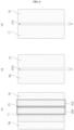
- FIG. 7A is a reference view illustrating the occurrence of an uncleaned region in a robot cleaner with spin mops.
- a zigzag-pattern travel of a conventional robot cleaner may effectively eliminate uncleaned regions.
- an uncleaned region is left behind in the central part of the robot cleaner, and as a result, the conventional zigzag-pattern travel cannot be used without change to eliminate uncleaned regions.
- an uncleaned region mc due to the spin-mops may occur.
- the left spin-mop 41a and the right spin-mop 41b move along the floor in the state of being in contact with the floor.
- an uncleaned region mc having a predetermined width d may occur between the movement trajectory L of the left spin-mop 41a and the movement trajectory R of the right spin-mop 41b.
- the robot cleaner is designed such that the left spin-mop 41a and the right spin-mop 41b, which are independent rotational bodies, are in contact with each other, the left spin-mop 41a and the right spin-mop 41b may interfere with each other. For this reason, it is necessary to provide a margin necessary for preventing such interference. As a result, a margin region is formed between the left spin-mop 41a and the right spin-mop 41b. Due to this margin region, an uncleaned region mc, which has not been cleaned, may occur even when the robot cleaner travels straight.
- the spin-mops 41a and 41b may be inclined such that the robot cleaner travels using the spin-mops 41a and 41b.
- an uncleaned region mc may occur at the central part of the robot cleaner, at which the frictional force is relatively low.
- an uncleaned region mc, which occurs when the robot cleaner travels straight may repeatedly occur when the robot cleaner travels in a zigzag pattern, in which the robot cleaner travels straight in a reciprocating fashion.
- the robot cleaner may use a traveling method capable of preventing the occurrence of an uncleaned region mc while a robot cleaner that performs a mopping operation travels according to a conventional intuitive travel motion.
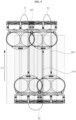
- FIG. 7B is a reference view illustrating a method of controlling the travel of the robot cleaner according to the embodiment of the present disclosure.
- the controller 550 may perform control such that the robot cleaner travels in a zigzag pattern including a first travel segment m1, in which the robot cleaner travels straight in a first direction, and a second travel segment m2, in which the robot cleaner travels straight in a second direction, which is opposite the first direction.
- the controller may perform control such that the direction in which the robot cleaner returns is set in order to cover an uncleaned region and then travels in the zigzag pattern. That is, the controller 550 may perform control such that the movement trajectory L2 of the left spin-mop 41a or the movement trajectory R2 of the right spin-mop 41b during the second travel m2 overlaps the movement trajectory L1 of the left spin-mop 41a and the movement trajectory R1 of the right spin-mop 41b during the first travel m1.
- the controller 550 may perform control such that, based on the direction in which the robot cleaner turns for returning during the zigzag-pattern travel of the robot cleaner, the movement trajectory of one of the spin-mops 41a and 41b overlaps both the movement trajectories L1 and R1 of the spin-mops 41a and 41b during the previous straight travel.
- FIG. 7B shows the case in which the robot cleaner performs the first travel m1 in the upward direction and then performs the second travel m2 in the downward direction while turning to the right or after turning to the right.
- the controller 550 may perform control such that the movement trajectory L2 of the left spin-mop 41a during the second travel m2 overlaps both the movement trajectories L1 and R1 of the spin-mops 41a and 41b during the previous straight travel m1. Consequently, an uncleaned region occurring during the first straight travel may be cleaned during the second straight travel, thereby preventing the occurrence of an uncleaned region.
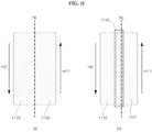
- FIGS. 8 to 14 are reference views illustrating various methods of controlling the travel of the robot cleaner according to the embodiment of the present disclosure.
- a first travel m1 when the robot cleaner performs a first travel m1, during which the robot cleaner travels upward (e.g., in a first direction) straight, an uncleaned region mc1 having a predetermined width d may occur between the movement trajectory L1 of the left spin-mop 41a and the movement trajectory R1 of the right spin-mop 41b.
- an uncleaned region mc2 having a predetermined width d may occur between the movement trajectory L2 of the left spin-mop 41a and the movement trajectory R2 of the right spin-mop 41b.
- the first travel m1, during which the robot cleaner travels upward straight, and the second travel m2, during which the robot cleaner travels downward straight may be controlled such that overlapping sections occur appropriately in order to remove the uncleaned regions.
- the controller 550 may perform control such that the movement trajectory L2 of the left spin-mop 41a during the second travel m2 overlaps both the movement trajectories L1 and R1 of the spin-mops 41a and 41b during the previous straight travel m1 at overlapping sections 810 and 820 in order to remove the uncleaned regions.
- the controller 550 may perform control such that the first travel m1 and the second travel m2 are repeatedly performed in sequence. That is, the controller 550 may perform control such that, after the first travel m1 in a first direction and the second travel m2 in a direction opposite the first direction, the first travel m1 and the second travel m2 are sequentially performed, and then the first travel m1 and the second travel m2 are sequentially performed again.
- the controller 550 may perform control such that a third travel, during which the robot cleaner travels straight in the first direction, is performed after the second travel m2. In this case, the controller 550 may perform control such that the movement trajectory of the left spin-mop or the right spin-mop during the third travel overlaps the movement trajectory of the left spin-mop and the movement trajectory of the right spin-mop during the second travel.
- the robot cleaner may travel such that overlapping sections occur during the second and third travels m2 and m3, in the same manner as during the first and second travels m1 and m2.
- the controller 550 may perform control such that the movement trajectory of the left spin-mop or the right spin-mop during the third travel m3 overlaps the movement trajectory of the left spin-mop and the movement trajectory of the right spin-mop during the second travel m2.
- the next travel m4 may be performed so as to overlap the third travel m3 in the same manner.
- the controller 550 may perform control such that the movement trajectory of one of the left and right spin-mops during an (N+1)-th straight travel overlaps both the movement trajectory of the left spin-mop and the movement trajectory of the right spin-mop during an N-th straight travel. That is, the controller 550 may perform control such that the robot cleaner continues to travel in an overlapping zigzag pattern including overlapping sections that are formed during straight travels performed in a zigzag pattern.
- the radius of a turning travel T1 for determining the direction in which the robot cleaner is to return after the first travel m1 may be less than the radius of a turning travel T2 for determining the direction in which the robot cleaner is to return after the second travel m2. That is, when the robot cleaner travels in an overlapping zigzag pattern, turning of the robot cleaner after traveling in a predetermined direction may be performed in a radius that is smaller than that of turning of the robot cleaner after traveling in an opposite direction, whereby the cleaning ranges may be different from each other during two straight travels that form a pair.
- the controller 550 may perform control such that, after the first and second travels m1 and m2 that have predetermined overlapping sections, the next travel is performed in another pattern.
- the controller 550 may perform control such that a fourth travel m11, in which the robot travels straight in the first direction, is performed after the second travel m2.
- the movement trajectory 1120 of the left spin-mop 41a or the right spin-mop 41b during the fourth travel m11 does not overlap the movement trajectory of the left spin-mop or the movement trajectory 1110 of the right spin-mop during the second travel.
- controller 550 may perform control such that the next travel m12, which forms a pair with the fourth travel m11, in which the robot travels straight in the first direction, has overlapping sections in the same manner as the first and second travels m1 and m2. In this embodiment, it is possible to minimize an overlapping region during zigzag cleaning, which may occur when the overlapping zigzag motion described with reference to FIG. 9 is performed.
- the radius of a turning travel T1 for determining the direction in which the robot cleaner is to return after the first travel m1 may be less than the radius of a turning travel T3 for determining the direction in which the robot cleaner is to perform the returning travel m11 after the second travel m2. That is, when the robot cleaner travels in an overlapping zigzag pattern, turning of the robot cleaner after traveling in a predetermined direction may be performed so as to be smaller than turning of the robot cleaner after traveling in an opposite direction, whereby the cleaning ranges may be different from each other during two straight travels that form a pair.
- the robot cleaner may turn with a greater radius than during the turning travel T2 in the embodiment of FIG. 9 , thereby achieving a further increase in speed.
- the movement trajectory 1120 of the left spin-mop or the right spin-mop during the fourth travel m11 and the movement trajectory of the left spin-mop or the movement trajectory 1110 of the right spin-mop during the second travel may be divided from each other on the basis of a reference line NL, whereby no overlapping section occurs.
- the robot cleaner is not ideally controlled depending on the travel environment and the state of the robot cleaner, and therefore an uncleaned region may occur between the movement trajectories 1110 and 1120.
- a predetermined design margin may be set. Referring to section (b) of FIG. 11 , the controller 550 may perform control such that the movement trajectory 1121 of one of the left and right spin-mops during the fourth travel m11 overlaps the movement trajectory 1110 of one of the left and right spin-mops during the second travel m2 at an overlapping section 1115. That is, the controller 550 may control the fourth travel m11 so as to overlap the outermost trajectory 1110 during the second travel m2.
- a straight travel following the fourth travel m11 may overlap both the movement trajectory of the left spin-mop and the movement trajectory 1110 of the right spin-mop during the fourth travel m11, like the relationship between the first and second travels m1 and m2.
- the controller 550 may perform control such that the above travel pattern is repeatedly performed.
- the controller 550 may perform control to repeatedly perform a travel pattern in which an N-th straight travel (e.g. a first travel m1), an (N+1)-th straight travel (e.g. a second travel m2), an (N+2)-th straight travel (e.g. a fourth travel m11), and an (N+3)-th straight travel are sequentially performed.
- N-th straight travel e.g. a first travel m1
- an (N+1)-th straight travel e.g. a second travel m2
- an (N+2)-th straight travel e.g. a fourth travel m11
- an (N+3)-th straight travel are sequentially performed.
- the controller 550 may perform control such that the movement trajectory of one of the left and right spin-mops during the (N+1)-th straight travel overlaps both the movement trajectory of the left spin-mop and the movement trajectory of the right spin-mop during the N-th straight travel, such that the movement trajectory of one of the left and right spin-mops during the (N+2)-th straight travel overlaps the movement trajectory of one of the left and right spin-mops during the (N+1)-th straight travel, and such that the movement trajectory of one of the left and right spin-mops during the (N+3)-th straight travel overlaps both the movement trajectory of the left spin-mop and the movement trajectory of the right spin-mop during the (N+2)-th straight travel.
- the robot cleaner according to the embodiment of the present disclosure may not perform direction-change turning after stoppage but may perform a direction-change motion in order to perform direction change, which is repeatedly performed during a zigzag-pattern travel.
- the robot cleaner slides in the order of 1a -> 1b -> 1c without stopping a motion according to sliding of the spin-mops 41a and 41b on the floor in order to perform distance and direction adjustment.
- the robot cleaner may travel according to various motions. For example, even when the robot cleaner turns in the same direction, the rotational radius and speed of the robot cleaner may be variously changed, whereby the robot cleaner may travel variously.
- the controller 550 may perform control such that the left spin-mop 41a and the right spin-mop 41b are rotated in the same direction at different speeds in order to turn the robot cleaner.
- the left spin-mop 41a and the right spin-mop 41b may be rotated in the same direction in order to set the rotational direction of the robot cleaner, and the left spin-mop 41a and the right spin-mop 41b may be rotated at different speeds in order to set the rotational direction of the robot cleaner.
- the controller 550 may perform control such that the left spin-mop 41a and the right spin-mop 41b are rotated in opposite directions at different speeds in order to turn the robot cleaner. That is, the robot cleaner may turn while the left spin-mop 41a and the right spin-mop 41b are rotated in opposite directions.
- the robot cleaner may turn to the right while the left spin-mop 41a and the right spin-mop 41b are rotated in opposite directions, i.e. in the inward directions when viewed from below.
- the controller 550 may perform control such that, in order to turn the robot cleaner, the left spin-mop 41a is rotated in the counterclockwise direction at a speed lower than the speed of the right spin-mop 41b in the state in which the right spin-mop 41b is rotated in the clockwise direction when viewed from below.
- the greatest frictional force generated between the left spin-mop 41a and the floor when the left spin-mop 41a is rotated is applied to a point on the lower surface of the left spin-mop 41a that is located on the right side of the center of rotation of the left spin-mop 41a.
- the point is located on the right side of the center of rotation.
- the point may be located in front of the right side of the center of rotation or at the rear of the right side of the center of rotation.
- the greatest frictional force generated between the right spin-mop 41b and the floor when the right spin-mop 41b is rotated is applied to a point on the lower surface of the right spin-mop 41b that is located on the left side of the center of rotation of the right spin-mop 41b.
- the greatest frictional force may be generated at the point.
- the point is located on the left side of the center of rotation.
- the point may be located in front of the left side of the center of rotation or behind the left side of the center of rotation.
- the robot cleaner travels due to the frictional force generated between the spin-mops 41a and 41b and the floor.
- the spin-mops 41a and 41b may generate a forward-movement frictional force for moving the main body 20 forward or a rearward-movement frictional force for moving the main body 20 rearward.
- the spin-mops 41a and 41b may generate a leftward-moment frictional force for turning the main body 20 to the left or a rightward-moment frictional force for turning the main body 20 to the right.
- the spin-mops 41a and 41b may generate a combination of one of the forward-movement and rearward-movement frictional forces and one of the leftward-moment and rightward-moment frictional forces.
- the left spin-mop 41a may be rotated in a first forward direction at a predetermined rpm, and the right spin-mop 41b may be rotated in a second forward direction at the predetermined rpm.
- the left spin-mop 41a may be rotated in a first reverse direction at a predetermined rpm, and the right spin-mop 41b may be rotated in a second reverse direction at the predetermined rpm.
- the left spin-mop 41a may be rotated in the first forward direction at a predetermined rpm, and the right spin-mop 41b may be rotated in the second reverse direction, may be stopped without being rotated, or may be rotated in the second forward direction at an rpm lower than the predetermined rpm.
- the right spin-mop 41b may be rotated in the second forward direction at a predetermined rpm, and the left spin-mop 41a may be rotated in the first reverse direction, may be stopped without being rotated, or may be rotated in the first forward direction at an rpm lower than the predetermined rpm.
- the robot cleaner may turn to the right while the left spin-mop 41a and the right spin-mop 41b are rotated in opposite directions, i.e. in the outward directions when viewed from below.
- the controller 550 may perform control such that, in order to turn the robot cleaner, the left spin-mop 41a is rotated in the clockwise direction at a speed higher than the speed of the right spin-mop 41b in the state in which the right spin-mop 41b is rotated in the counterclockwise direction when viewed from below.
- the two spin-mops 41a and 41b are independently driven, whereby the freedom of travel speed and motion is high.
- the robot cleaner is capable of traveling while completely cleaning a floor without allowing an uncleaned region to remain.
- the robot cleaner has an increased travel speed and cleaning speed and improved cleaning performance and a method of controlling the same.
- the robot cleaner is capable of performing a travel appropriate for the circumstances using various travel motions.
- the robot cleaner is capable of performing either wet cleaning or dry cleaning as needed.
- the robot cleaner according to the present disclosure and the method of controlling the same are not limitedly applied to the constructions and methods of the embodiments as previously described, and all or some of the embodiments may be selectively combined to achieve various modifications.
- a robot cleaner including a first cleaning module including a left spin-mop and a right spin-mop configured to contact a floor while rotating in a clockwise direction or in a counterclockwise direction when viewed from above and a controller for performing control such that, when the robot cleaner travels in a zigzag pattern including a first travel, during which the robot cleaner travels straight in a first direction, and a second travel, during which the robot cleaner travels straight in a second direction, which is opposite the first direction, the movement trajectory of the left spin-mop or the right spin-mop during the second travel overlaps the movement trajectory of the left spin-mop and a movement trajectory of the right spin-mop during the first travel, whereby the robot cleaner is capable of traveling rapidly while completely cleaning the floor without allowing an uncleaned region to remain.
- first, second, third, etc. may be used herein to describe various elements, components, regions, layers and/or sections, these elements, components, regions, layers and/or sections should not be limited by these terms. These terms are only used to distinguish one element, component, region, layer or section from another region, layer or section. Thus, a first element, component, region, layer or section could be termed a second element, component, region, layer or section without departing from the teachings of the present disclosure.
- spatially relative terms such as “lower”, “upper” and the like, may be used herein for ease of description to describe the relationship of one element or feature to another element(s) or feature(s) as illustrated in the figures. It will be understood that the spatially relative terms are intended to encompass different orientations of the device in use or operation, in addition to the orientation depicted in the figures. For example, if the device in the figures is turned over, elements described as “lower” relative to other elements or features would then be oriented “upper” relative the other elements or features. Thus, the exemplary term “lower” can encompass both an orientation of above and below. The device may be otherwise oriented (rotated 90 degrees or at other orientations) and the spatially relative descriptors used herein interpreted accordingly.
- Embodiments of the disclosure are described herein with reference to cross-section illustrations that are schematic illustrations of idealized embodiments (and intermediate structures) of the disclosure. As such, variations from the shapes of the illustrations as a result, for example, of manufacturing techniques and/or tolerances, are to be expected. Thus, embodiments of the disclosure should not be construed as limited to the particular shapes of regions illustrated herein but are to include deviations in shapes that result, for example, from manufacturing.
- any reference in this specification to "one embodiment,” “an embodiment,” “example embodiment,” etc. means that a particular feature, structure, or characteristic described in connection with the embodiment is included in at least one embodiment of the disclosure.
- the appearances of such phrases in various places in the specification are not necessarily all referring to the same embodiment.
Landscapes
- Engineering & Computer Science (AREA)
- Mechanical Engineering (AREA)
- Robotics (AREA)
- Electric Vacuum Cleaner (AREA)
- Control Of Position, Course, Altitude, Or Attitude Of Moving Bodies (AREA)
- Aviation & Aerospace Engineering (AREA)
- Radar, Positioning & Navigation (AREA)
- Remote Sensing (AREA)
- Physics & Mathematics (AREA)
- General Physics & Mathematics (AREA)
- Automation & Control Theory (AREA)
Claims (15)
- Roboterreiniger, der Folgendes umfasst:einen ersten rotierenden Mopp (41a) und einen zweiten rotierenden Mopp (41b), die so konfiguriert sind, dass sie mit dem Boden in Kontakt sind, während sie sich drehen; undeine Steuerung (580), die konfiguriert ist, die jeweiligen Drehrichtungen und Drehzahlen des ersten rotierenden Mopps (41a) und des zweiten rotierenden Mopps (41b) zu steuern, um den Roboterreiniger zu bewegen;dadurch gekennzeichnet, dass die Steuerung (580) konfiguriert ist, den Roboterreiniger so zu bewegen, dass:sich der Roboterreiniger in einem Zickzackmuster bewegt, das eine erste Bewegung, während der sich der Roboterreiniger in einer ersten Richtung bewegt, und eine zweite Bewegung, während der sich der Roboterreiniger in einer zweiten Richtung bewegt, die entgegengesetzt zur ersten Richtung ist, umfasst,wobei sich der erste rotierende Mopp (41a) oder der zweite rotierende Mopp (41b) während der zweiten Bewegung über einen ersten Bereich des Bodens bewegt,wobei sich der erste rotierende Mopp (41a) während der ersten Bewegung über einen zweiten Bereich des Bodens bewegt,wobei sich der zweite rotierende Mopp (41b) während der ersten Bewegung über einen dritten Bereich des Bodens bewegt,wobei zwischen dem zweiten Bereich des Bodens, über den sich der erste rotierende Mopp (41a) während der ersten Bewegung bewegt, und dem dritten Bereich des Bodens, über den sich der zweite rotierende Mopp (41b) während der ersten Bewegung bewegt, ein nicht gereinigter Bereich vorhanden ist, undwobei der erste Bereich des Bodens, über den sich der erste rotierende Mopp (41a) oder der zweite rotierende Mopp (41b) während der zweiten Bewegung bewegt, den nicht gereinigten Bereich, den zweiten Bereich und den dritten Bereich überlappt.
- Roboterreiniger nach Anspruch 1, wobei die Steuerung (580) die Drehrichtungen und Drehzahlen des ersten rotierenden Mopps (41a) und des zweiten rotierenden Mopps (41b) wahlweise ändert, um eine Drehrichtung und einen Drehradius des Roboterreinigers zu steuern.
- Roboterreiniger nach einem der vorhergehenden Ansprüche, wobei die Steuerung (580) ferner die jeweiligen Drehrichtungen und Drehzahlen des ersten rotierenden Mopps (41a) und des zweiten rotierenden Mopps (41b) so steuert, dass:das Zickzackmuster eine dritte Bewegung umfasst, während der sich der Roboterreiniger nach der zweiten Bewegung in der ersten Richtung bewegt, undein vierter Bereich des Bodens, über den sich der erste rotierende Mopp (41a) oder der zweite rotierende Mopp (41b) während der dritten Bewegung bewegt, den ersten Bereich des Bodens, über den sich der erste rotierende Mopp (41a) oder der zweite rotierende Mopp während der zweiten Bewegung bewegt, und einen fünften Bereich des Bodens, über den sich der jeweils andere des ersten rotierenden Mopps (41a) und des zweiten rotierenden Mopps (41b) während der zweiten Bewegung bewegt, überlappt.
- Roboterreiniger nach Anspruch 3, wobei die Steuerung (580) ferner die jeweiligen Drehrichtungen und Drehzahlen des ersten rotierenden Mopps (41a) und des zweiten rotierenden Mopps (41b) so steuert, dass ein Bereich des Bodens, über den sich der erste oder der zweite rotierende Mopp (41a, 41b) während einer (N + 1)-ten geradlinigen Bewegung bewegt, beide Bereiche des Bodens überlappt, über die sich der erste rotierende Mopp (41a) und der zweite rotierende Mopp (41b) während einer N-ten geradlinigen Bewegung bewegen.
- Roboterreiniger nach einem der vorhergehenden Ansprüche, wobei die Steuerung (580) die jeweiligen Drehrichtungen und Drehzahlen des ersten rotierenden Mopps (41a) und des zweiten rotierenden Mopps (41b) so steuert, dass die erste Bewegung und die zweite Bewegung der Reihe nach wiederholt ausgeführt werden.
- Roboterreiniger nach einem der vorhergehenden Ansprüche, wobei die Steuerung (580) ferner die jeweiligen Drehrichtungen und Drehzahlen des ersten rotierenden Mopps (41a) und des zweiten rotierenden Mopps (41b) so steuert, dass:das Zickzackmuster eine vierte Bewegung umfasst, bei der sich der Roboterreiniger nach der zweiten Bewegung in der ersten Richtung bewegt, undein vierter Bereich des Bodens, über den sich der erste rotierende Mopp oder der zweite rotierende Mopp (41b) während der vierten Bewegung bewegt, den zweiten Bereich, über den sich der erste Mopp während der zweiten Bewegung bewegt, oder den dritten Bereich, über den sich der zweite rotierende Mopp (41b) während der zweiten Bewegung bewegt, überlappt.
- Roboterreiniger nach Anspruch 6, wobei die Steuerung (580) ferner die jeweiligen Drehrichtungen und Drehzahlen des ersten rotierenden Mopps (41a) und des zweiten rotierenden Mopps (41b) so steuert, dass:der Roboterreiniger ein Bewegungsmuster wiederholt ausführt, bei dem eine N-te geradlinige Bewegung, eine (N + 1)-te geradlinige Bewegung, eine (N + 2)-te geradlinige Bewegung und eine (N + 3)-te geradlinige Bewegung der Reihe nach ausgeführt werden,ein Bereich des Bodens, über den sich der erste oder der zweite rotierende Mopp (41a, 41b) während der (N + 1)-ten geradlinigen Bewegung bewegt, beide Bereiche des Bodens überlappt, über die sich der erste rotierende Mopp (41a) und der zweite rotierende Mopp (41b) während der N-ten geradlinigen Bewegung bewegen,ein Bereich des Bodens, über den sich der erste oder der zweite rotierende Mopp (41a, 41b) während der (N + 2)-ten geradlinigen Bewegung bewegt, einen Bereich des Bodens überlappt, über den sich der erste oder der zweite rotierende Mopp während der (N + 1)-ten geradlinigen Bewegung bewegt, undein Bereich des Bodens, über den sich der erste oder der zweite rotierende Mopp (41a, 41b) während der (N + 3)-ten geradlinigen Bewegung bewegt, beide Bereiche des Bodens überlappt, über die sich der erste rotierende Mopp (41a) und der zweite rotierende Mopp (41b) während der (N + 2)-ten geradlinigen Bewegung bewegen.
- Roboterreiniger nach einem der vorhergehenden Ansprüche, wobei die Steuerung (580) den ersten rotierenden Mopp (41a) und den zweiten rotierenden Mopp (41b) so steuert, dass sich der erste rotierende Mopp (41a) und der zweite rotierende Mopp (41b) in entgegengesetzten Richtungen mit unterschiedlichen Drehzahlen drehen, um den Roboterreiniger zu drehen.
- Roboterreiniger nach einem der vorhergehenden Ansprüche, wobei die Steuerung (580) den ersten rotierenden Mopp (41a) und den zweiten rotierenden Mopp (41b) so steuert, dass sich der erste rotierende Mopp (41a) und der zweite rotierende Mopp (41b) mit unterschiedlichen Drehzahlen in einer gemeinsamen Drehrichtung drehen, um den Roboterreiniger zu drehen.
- Roboterreiniger nach einem der vorhergehenden Ansprüche, der ferner eine Wasserzufuhr umfasst, die dem ersten rotierenden Mopp (41a) und dem zweiten rotierenden Mopp Wasser zuführt.
- Roboterreiniger nach einem der vorhergehenden Ansprüche, wobei der erste rotierende Mopp (41a) und der zweite rotierende Mopp (41b) in einem ersten Reinigungsmodul (520) enthalten sind, und wobei der Roboterreiniger ferner ein zweites Reinigungsmodul (530) umfasst, das vom ersten rotierenden Mopp (41a) und vom zweiten rotierenden Mopp (41b) in einer Vorwärtsrichtung oder Rückwärtsrichtung beabstandet ist.
- Roboterreiniger nach Anspruch 11, wobei das zweite Reinigungsmodul (530) Fremdstoffe vom Boden sammelt.
- Roboterreiniger nach Anspruch 12, wobei das zweite Reinigungsmodul (530) Folgendes umfasst:
Walzen (51a, 51b) zum Kehren, die sich so drehen, dass sie mit dem Boden in Kontakt sind, und Fremdstoffe auf dem Boden in das zweite Reinigungsmodul (530) leiten. - Roboterreiniger nach einem der vorhergehenden Ansprüche, wobei der erste rotierende Mopp (41a) und der zweite rotierende Mopp (41b) zur Mitte des Roboterreinigers aufwärts geneigt sind.
- Roboterreiniger nach Anspruch 1, wobei die Steuerung (580) konfiguriert ist, ferner die jeweiligen Drehrichtungen und Drehzahlen des ersten rotierenden Mopps (41a) und des zweiten rotierenden Mopps (41b) zu steuern, um den Roboterreiniger so zu bewegen, dass das Zickzackmuster Folgendes umfasst:eine weitere Bewegung (m11), während der sich der Roboterreiniger nach der zweiten Bewegung (m2) in der ersten Richtung bewegt, undwobei ein weiterer Bereich des Bodens, über den sich der erste rotierende Mopp (41a) oder der zweite rotierende Mopp (41b) während der weiteren Bewegung (m11) bewegt, nicht den ersten Bereich des Bodens überlappt, über den sich der erste rotierende Mopp (41a) oder der zweite rotierende Mopp (41b) während der zweiten Bewegung bewegt.
Applications Claiming Priority (2)
| Application Number | Priority Date | Filing Date | Title |
|---|---|---|---|
| KR1020170099752A KR102014142B1 (ko) | 2017-08-07 | 2017-08-07 | 로봇 청소기 |
| EP18187630.1A EP3440981B1 (de) | 2017-08-07 | 2018-08-07 | Roboterreiniger |
Related Parent Applications (1)
| Application Number | Title | Priority Date | Filing Date |
|---|---|---|---|
| EP18187630.1A Division EP3440981B1 (de) | 2017-08-07 | 2018-08-07 | Roboterreiniger |
Publications (2)
| Publication Number | Publication Date |
|---|---|
| EP3875014A1 EP3875014A1 (de) | 2021-09-08 |
| EP3875014B1 true EP3875014B1 (de) | 2023-10-04 |
Family
ID=63168290
Family Applications (2)
| Application Number | Title | Priority Date | Filing Date |
|---|---|---|---|
| EP21170404.4A Active EP3875014B1 (de) | 2017-08-07 | 2018-08-07 | Roboterreiniger |
| EP18187630.1A Active EP3440981B1 (de) | 2017-08-07 | 2018-08-07 | Roboterreiniger |
Family Applications After (1)
| Application Number | Title | Priority Date | Filing Date |
|---|---|---|---|
| EP18187630.1A Active EP3440981B1 (de) | 2017-08-07 | 2018-08-07 | Roboterreiniger |
Country Status (4)
| Country | Link |
|---|---|
| US (1) | US10772478B2 (de) |
| EP (2) | EP3875014B1 (de) |
| KR (1) | KR102014142B1 (de) |
| TW (1) | TWI691297B (de) |
Families Citing this family (19)
| Publication number | Priority date | Publication date | Assignee | Title |
|---|---|---|---|---|
| KR101918228B1 (ko) | 2016-07-14 | 2019-01-29 | 엘지전자 주식회사 | 이동로봇 및 그 제어방법 |
| US20190329809A1 (en) * | 2016-11-15 | 2019-10-31 | Concourse Golf Pty Ltd | Electrically motorised wheel, transmission and control module, kit, vehicle and system |
| CN109875463A (zh) * | 2019-03-04 | 2019-06-14 | 深圳市银星智能科技股份有限公司 | 清洁机器人及其清洁方法 |
| KR102811450B1 (ko) | 2019-07-31 | 2025-05-21 | 엘지전자 주식회사 | 인공지능 로봇청소기 및 그를 포함하는 로봇 시스템 |
| KR102293657B1 (ko) * | 2019-07-31 | 2021-08-24 | 엘지전자 주식회사 | 이동 로봇 |
| KR102745306B1 (ko) * | 2019-09-17 | 2024-12-20 | 엘지전자 주식회사 | 청소기 |
| DE102019125470A1 (de) * | 2019-09-23 | 2021-03-25 | Hako Gmbh | Bodenreinigungsmaschine und Verfahren zum Reinigen einer Bodenfläche |
| KR102804651B1 (ko) | 2020-04-24 | 2025-05-12 | 엘지전자 주식회사 | 로봇 청소기 및 로봇 청소기의 제어방법 |
| KR102804650B1 (ko) * | 2020-04-24 | 2025-05-12 | 엘지전자 주식회사 | 로봇 청소기 및 로봇 청소기의 제어방법 |
| CN113729572B (zh) * | 2020-05-29 | 2022-12-06 | 宝时得科技(中国)有限公司 | 清洁机器人及其控制方法 |
| KR102814002B1 (ko) | 2020-07-17 | 2025-05-30 | 엘지전자 주식회사 | 로봇 청소기 |
| KR102804685B1 (ko) | 2020-07-17 | 2025-05-12 | 엘지전자 주식회사 | 로봇 청소기 |
| US12461525B2 (en) | 2020-09-01 | 2025-11-04 | Ceva Technologies, Inc. | Planar robots dead-reckoning with optical flow, wheel encoder and inertial measurement unit |
| CN112493948B (zh) * | 2020-11-30 | 2024-04-12 | 追觅创新科技(苏州)有限公司 | 自清洁设备及清洁组件检测方法 |
| CN114098565B (zh) * | 2021-04-14 | 2023-05-16 | 曲阜信多达智能科技有限公司 | 清洁机的控制方法 |
| CN113180560B (zh) * | 2021-05-12 | 2022-11-11 | 深圳市伽利略机器人有限公司 | 一种两盘驱动式的全向行走装置及行走方法 |
| KR20230041918A (ko) * | 2021-09-17 | 2023-03-27 | 삼성전자주식회사 | Uwb 통신을 이용하는 로봇 청소기 및 그 제어 방법 |
| KR20230092551A (ko) | 2021-12-17 | 2023-06-26 | 엘지전자 주식회사 | 로봇청소기 및 그를 포함하는 로봇 시스템 |
| CN114642423B (zh) * | 2022-03-15 | 2024-07-12 | 大连理工大学 | 基于体验质量的下肢外骨骼机器人步态规划方法及系统 |
Family Cites Families (60)
| Publication number | Priority date | Publication date | Assignee | Title |
|---|---|---|---|---|
| US2988762A (en) * | 1960-02-08 | 1961-06-20 | Hugh H Babcock | Self-steering submarine suction cleaner |
| JP3424151B2 (ja) | 1997-01-29 | 2003-07-07 | 三菱電機株式会社 | 電気掃除機の床ノズル |
| US5998953A (en) | 1997-08-22 | 1999-12-07 | Minolta Co., Ltd. | Control apparatus of mobile that applies fluid on floor |
| KR100241620B1 (ko) | 1998-03-16 | 2000-04-01 | 구자홍 | 진공청소기의 걸레판 착탈장치 |
| SE518483C2 (sv) | 2001-02-28 | 2002-10-15 | Electrolux Ab | Hjulupphängning för en självgående städapparat |
| JP2004275468A (ja) * | 2003-03-17 | 2004-10-07 | Hitachi Home & Life Solutions Inc | 自走式掃除機およびその運転方法 |
| KR101026003B1 (ko) | 2003-05-07 | 2011-03-30 | 엘지전자 주식회사 | 로봇 진공청소기의 완충 및 감지장치 |
| KR20050012047A (ko) | 2003-07-24 | 2005-01-31 | 삼성광주전자 주식회사 | 회전 물걸레 청소유닛을 구비한 로봇청소기 |
| KR100661339B1 (ko) * | 2005-02-24 | 2006-12-27 | 삼성광주전자 주식회사 | 로봇 청소기 |
| KR200395016Y1 (ko) | 2005-05-10 | 2005-09-07 | 박연훈 | 회전식 스팀 청소기 |
| EP2806326B1 (de) | 2005-09-02 | 2016-06-29 | Neato Robotics, Inc. | Multifunktionale Robotervorrichtung |
| KR100674564B1 (ko) | 2005-09-08 | 2007-01-29 | 삼성광주전자 주식회사 | 액체공급 스테이션을 구비한 이동로봇 시스템 및액체공급방법 |
| KR100814507B1 (ko) | 2006-08-31 | 2008-03-18 | 에스이씨주식회사 | 회전 물 걸레 겸용 전방위 진공 스팀 청소기 |
| KR200437646Y1 (ko) | 2007-01-09 | 2007-12-18 | 황동산 | 탈착가능한 물통을 갖는 스팀청소기 |
| KR100835968B1 (ko) | 2007-02-28 | 2008-06-09 | 엘지전자 주식회사 | 로봇청소기 및 그에 따른 제어방법 |
| KR20080081626A (ko) | 2007-03-06 | 2008-09-10 | 주식회사 대우일렉트로닉스 | 걸레 착탈 장치 및 이를 구비하는 청소기 |
| KR100871114B1 (ko) | 2007-04-03 | 2008-11-28 | 엘지전자 주식회사 | 이동로봇 및 그 동작방법 |
| ES2559128T3 (es) | 2007-05-09 | 2016-02-10 | Irobot Corporation | Robot autónomo de cubrimiento compacto |
| KR101369220B1 (ko) | 2007-05-15 | 2014-03-06 | 삼성전자주식회사 | 스팀겸용 진공청소기의 흡입브러시 |
| CN102083352B (zh) | 2008-04-24 | 2014-10-15 | 艾罗伯特公司 | 用于机器人使能的移动产品的定位、位置控制和导航系统的应用 |
| US8961695B2 (en) | 2008-04-24 | 2015-02-24 | Irobot Corporation | Mobile robot for cleaning |
| KR101164291B1 (ko) | 2008-07-16 | 2012-07-09 | 엘지전자 주식회사 | 청소기의 노즐 |
| KR101052118B1 (ko) | 2008-12-26 | 2011-07-26 | 엘지전자 주식회사 | 청소기의 노즐 |
| WO2011052827A1 (ko) | 2009-10-30 | 2011-05-05 | 주식회사 유진로봇 | 이동 로봇의 슬립 감지 장치 및 방법 |
| KR101487778B1 (ko) | 2010-05-11 | 2015-01-29 | 삼성전자 주식회사 | 센싱 시스템 및 이를 갖춘 이동 로봇 |
| KR101338143B1 (ko) | 2010-11-30 | 2013-12-06 | 주식회사 유진로봇 | 이동 로봇의 슬립 감지 장치 및 방법 |
| KR101198522B1 (ko) | 2010-12-21 | 2012-11-06 | 엘지전자 주식회사 | 진공청소기 |
| AU2011265435B2 (en) | 2010-12-29 | 2014-04-24 | Bissell Inc. | Cleaning implement with mist generating system |
| WO2012092565A1 (en) * | 2010-12-30 | 2012-07-05 | Irobot Corporation | Debris monitoring |
| GB201103604D0 (en) | 2011-03-01 | 2011-04-13 | Stanley Black & Decker Inc | Steam cleaning apparatus |
| KR200458863Y1 (ko) | 2011-03-22 | 2012-03-15 | 어수곤 | 물걸레 로봇청소기 |
| KR20120129185A (ko) | 2011-05-19 | 2012-11-28 | 어수곤 | 물걸레 로봇청소기 |
| KR101495866B1 (ko) | 2011-11-15 | 2015-02-26 | 주식회사 한울로보틱스 | 로봇 청소기의 추락, 문턱 및 바닥재질 감지장치 및 이를 이용한 감지방법 |
| JP2014014455A (ja) | 2012-07-06 | 2014-01-30 | Nikon Corp | 清掃装置 |
| KR101822942B1 (ko) | 2012-07-18 | 2018-01-29 | 엘지전자 주식회사 | 로봇 청소기 및 이의 제어 방법 |
| KR102123247B1 (ko) | 2012-11-09 | 2020-06-17 | 삼성전자주식회사 | 로봇 청소기 |
| AU2014100004A4 (en) | 2013-01-11 | 2014-01-30 | Bissell Inc. | Vacuum cleaner |
| JP6166047B2 (ja) | 2013-01-16 | 2017-07-19 | シャープ株式会社 | 自走式電子機器 |
| US10159393B2 (en) | 2013-03-15 | 2018-12-25 | Omachron Intellectual Property Inc. | Surface cleaning apparatus |
| KR101520043B1 (ko) | 2013-07-24 | 2015-05-14 | 에브리봇 주식회사 | 물걸레 로봇청소기 및 청소제어방법 |
| KR102278899B1 (ko) | 2013-11-20 | 2021-07-20 | 삼성전자주식회사 | 청소 로봇 및 그 제어 방법 |
| KR20150073726A (ko) | 2013-12-23 | 2015-07-01 | 서울바이오시스 주식회사 | 자외선 발광 다이오드가 구비된 로봇 물걸레 청소기 |
| KR102117263B1 (ko) | 2013-12-30 | 2020-06-01 | 삼성전자주식회사 | 로봇 청소기 |
| KR101544667B1 (ko) | 2014-02-04 | 2015-08-21 | 박인태 | 청소기 |
| KR102137524B1 (ko) | 2014-02-13 | 2020-07-24 | 삼성전자주식회사 | 로봇청소기 |
| JP6537774B2 (ja) | 2014-02-28 | 2019-07-03 | 住友重機械工業株式会社 | 自走式清掃装置 |
| KR101578879B1 (ko) | 2014-03-11 | 2015-12-18 | 에브리봇 주식회사 | 로봇 청소기 및 그의 제어 방법 |
| KR101622740B1 (ko) * | 2014-03-14 | 2016-05-19 | 에브리봇 주식회사 | 로봇 청소기 및 그의 제어 방법 |
| KR101578872B1 (ko) * | 2014-05-02 | 2015-12-18 | 에브리봇 주식회사 | 로봇 청소기 및 그 제어 방법 |
| KR101689133B1 (ko) | 2014-06-02 | 2016-12-26 | 에브리봇 주식회사 | 로봇 청소기 및 그의 제어 방법 |
| EP3177974A1 (de) * | 2014-08-06 | 2017-06-14 | Alfred Kärcher GmbH & Co. KG | Verfahren zum bearbeiten einer bodenfläche und bodenbearbeitungsgerät |
| US10499778B2 (en) | 2014-09-08 | 2019-12-10 | Aktiebolaget Electrolux | Robotic vacuum cleaner |
| KR102321278B1 (ko) | 2015-01-22 | 2021-11-03 | 에브리봇 주식회사 | 로봇 청소기 및 로봇 청소기 제어 방법 |
| KR20160090567A (ko) | 2015-01-22 | 2016-08-01 | 주식회사 파인로보틱스 | 로봇 청소기 및 로봇 청소기 제어 방법 |
| KR101602790B1 (ko) | 2015-02-26 | 2016-03-11 | 에브리봇 주식회사 | 로봇 청소기 및 그의 제어 방법 |
| KR101678443B1 (ko) | 2015-09-23 | 2016-12-06 | 엘지전자 주식회사 | 로봇 청소기 |
| KR20170124216A (ko) | 2016-05-02 | 2017-11-10 | 삼성전자주식회사 | 청소로봇 및 그 제어 방법 |
| KR101654014B1 (ko) | 2016-06-21 | 2016-09-06 | 주식회사 파인로보틱스 | 걸레 로봇 청소기 |
| KR101918228B1 (ko) | 2016-07-14 | 2019-01-29 | 엘지전자 주식회사 | 이동로봇 및 그 제어방법 |
| CN108209744A (zh) * | 2017-12-18 | 2018-06-29 | 深圳市奇虎智能科技有限公司 | 清洁方法、装置、计算机设备和存储介质 |
-
2017
- 2017-08-07 KR KR1020170099752A patent/KR102014142B1/ko active Active
-
2018
- 2018-08-06 TW TW107127312A patent/TWI691297B/zh active
- 2018-08-07 EP EP21170404.4A patent/EP3875014B1/de active Active
- 2018-08-07 US US16/057,572 patent/US10772478B2/en active Active
- 2018-08-07 EP EP18187630.1A patent/EP3440981B1/de active Active
Also Published As
| Publication number | Publication date |
|---|---|
| TW201909822A (zh) | 2019-03-16 |
| KR20190015929A (ko) | 2019-02-15 |
| EP3440981B1 (de) | 2021-04-28 |
| KR102014142B1 (ko) | 2019-08-26 |
| TWI691297B (zh) | 2020-04-21 |
| EP3440981A1 (de) | 2019-02-13 |
| EP3875014A1 (de) | 2021-09-08 |
| US10772478B2 (en) | 2020-09-15 |
| US20190150692A1 (en) | 2019-05-23 |
Similar Documents
| Publication | Publication Date | Title |
|---|---|---|
| EP3440981B1 (de) | Roboterreiniger | |
| TWI663949B (zh) | 清掃機器人 | |
| US9504367B2 (en) | Cleaning robot and method for controlling the same | |
| TWI679959B (zh) | 清掃機器人及其控制方法 | |
| US9854956B2 (en) | Robot cleaner and control method thereof | |
| US8483881B2 (en) | Localization and mapping system and method for a robotic device | |
| US12329350B2 (en) | Robotic cleaner | |
| CN103054519B (zh) | 机器人吸尘器以及用于控制该机器人吸尘器的方法 | |
| JP2013085958A (ja) | ロボット掃除機及びその制御方法 | |
| CN117084597A (zh) | 传动装置、自动清洁设备和清洁机器人系统 | |
| TWI715939B (zh) | 自律行走型掃除機 | |
| CN118592844B (zh) | 清洁设备控制方法和清洁设备 | |
| AU2024335225A1 (en) | Transmission apparatus, automatic cleaning device and cleaning robot system | |
| WO2017108077A1 (en) | Controlling movement of a robotic cleaning device | |
| US20250194890A1 (en) | Robot cleaner and robot system comprising same | |
| CN114174011A (zh) | 移动机器人及移动机器人的移动距离计算方法 | |
| KR20150075638A (ko) | 로봇 청소기 |
Legal Events
| Date | Code | Title | Description |
|---|---|---|---|
| PUAI | Public reference made under article 153(3) epc to a published international application that has entered the european phase |
Free format text: ORIGINAL CODE: 0009012 |
|
| STAA | Information on the status of an ep patent application or granted ep patent |
Free format text: STATUS: REQUEST FOR EXAMINATION WAS MADE |
|
| 17P | Request for examination filed |
Effective date: 20210426 |
|
| AC | Divisional application: reference to earlier application |
Ref document number: 3440981 Country of ref document: EP Kind code of ref document: P |
|
| AK | Designated contracting states |
Kind code of ref document: A1 Designated state(s): AL AT BE BG CH CY CZ DE DK EE ES FI FR GB GR HR HU IE IS IT LI LT LU LV MC MK MT NL NO PL PT RO RS SE SI SK SM TR |
|
| GRAP | Despatch of communication of intention to grant a patent |
Free format text: ORIGINAL CODE: EPIDOSNIGR1 |
|
| RIC1 | Information provided on ipc code assigned before grant |
Ipc: A47L 9/28 20060101ALI20230131BHEP Ipc: A47L 11/40 20060101ALI20230131BHEP Ipc: A47L 11/30 20060101ALI20230131BHEP Ipc: A47L 11/293 20060101ALI20230131BHEP Ipc: A47L 11/16 20060101AFI20230131BHEP |
|
| STAA | Information on the status of an ep patent application or granted ep patent |
Free format text: STATUS: GRANT OF PATENT IS INTENDED |
|
| GRAS | Grant fee paid |
Free format text: ORIGINAL CODE: EPIDOSNIGR3 |
|
| INTG | Intention to grant announced |
Effective date: 20230309 |
|
| GRAA | (expected) grant |
Free format text: ORIGINAL CODE: 0009210 |
|
| STAA | Information on the status of an ep patent application or granted ep patent |
Free format text: STATUS: THE PATENT HAS BEEN GRANTED |
|
| AC | Divisional application: reference to earlier application |
Ref document number: 3440981 Country of ref document: EP Kind code of ref document: P |
|
| AK | Designated contracting states |
Kind code of ref document: B1 Designated state(s): AL AT BE BG CH CY CZ DE DK EE ES FI FR GB GR HR HU IE IS IT LI LT LU LV MC MK MT NL NO PL PT RO RS SE SI SK SM TR |
|
| REG | Reference to a national code |
Ref country code: GB Ref legal event code: FG4D |
|
| REG | Reference to a national code |
Ref country code: CH Ref legal event code: EP |
|
| REG | Reference to a national code |
Ref country code: DE Ref legal event code: R096 Ref document number: 602018059014 Country of ref document: DE |
|
| REG | Reference to a national code |
Ref country code: IE Ref legal event code: FG4D |
|
| REG | Reference to a national code |
Ref country code: LT Ref legal event code: MG9D |
|
| REG | Reference to a national code |
Ref country code: NL Ref legal event code: MP Effective date: 20231004 |
|
| REG | Reference to a national code |
Ref country code: AT Ref legal event code: MK05 Ref document number: 1616819 Country of ref document: AT Kind code of ref document: T Effective date: 20231004 |
|
| PG25 | Lapsed in a contracting state [announced via postgrant information from national office to epo] |
Ref country code: NL Free format text: LAPSE BECAUSE OF FAILURE TO SUBMIT A TRANSLATION OF THE DESCRIPTION OR TO PAY THE FEE WITHIN THE PRESCRIBED TIME-LIMIT Effective date: 20231004 |
|
| PG25 | Lapsed in a contracting state [announced via postgrant information from national office to epo] |
Ref country code: GR Free format text: LAPSE BECAUSE OF FAILURE TO SUBMIT A TRANSLATION OF THE DESCRIPTION OR TO PAY THE FEE WITHIN THE PRESCRIBED TIME-LIMIT Effective date: 20240105 |
|
| PG25 | Lapsed in a contracting state [announced via postgrant information from national office to epo] |
Ref country code: IS Free format text: LAPSE BECAUSE OF FAILURE TO SUBMIT A TRANSLATION OF THE DESCRIPTION OR TO PAY THE FEE WITHIN THE PRESCRIBED TIME-LIMIT Effective date: 20240204 |
|
| PG25 | Lapsed in a contracting state [announced via postgrant information from national office to epo] |
Ref country code: LT Free format text: LAPSE BECAUSE OF FAILURE TO SUBMIT A TRANSLATION OF THE DESCRIPTION OR TO PAY THE FEE WITHIN THE PRESCRIBED TIME-LIMIT Effective date: 20231004 |
|
| PG25 | Lapsed in a contracting state [announced via postgrant information from national office to epo] |
Ref country code: AT Free format text: LAPSE BECAUSE OF FAILURE TO SUBMIT A TRANSLATION OF THE DESCRIPTION OR TO PAY THE FEE WITHIN THE PRESCRIBED TIME-LIMIT Effective date: 20231004 |
|
| PG25 | Lapsed in a contracting state [announced via postgrant information from national office to epo] |
Ref country code: ES Free format text: LAPSE BECAUSE OF FAILURE TO SUBMIT A TRANSLATION OF THE DESCRIPTION OR TO PAY THE FEE WITHIN THE PRESCRIBED TIME-LIMIT Effective date: 20231004 |
|
| PG25 | Lapsed in a contracting state [announced via postgrant information from national office to epo] |
Ref country code: LT Free format text: LAPSE BECAUSE OF FAILURE TO SUBMIT A TRANSLATION OF THE DESCRIPTION OR TO PAY THE FEE WITHIN THE PRESCRIBED TIME-LIMIT Effective date: 20231004 Ref country code: IS Free format text: LAPSE BECAUSE OF FAILURE TO SUBMIT A TRANSLATION OF THE DESCRIPTION OR TO PAY THE FEE WITHIN THE PRESCRIBED TIME-LIMIT Effective date: 20240204 Ref country code: GR Free format text: LAPSE BECAUSE OF FAILURE TO SUBMIT A TRANSLATION OF THE DESCRIPTION OR TO PAY THE FEE WITHIN THE PRESCRIBED TIME-LIMIT Effective date: 20240105 Ref country code: ES Free format text: LAPSE BECAUSE OF FAILURE TO SUBMIT A TRANSLATION OF THE DESCRIPTION OR TO PAY THE FEE WITHIN THE PRESCRIBED TIME-LIMIT Effective date: 20231004 Ref country code: BG Free format text: LAPSE BECAUSE OF FAILURE TO SUBMIT A TRANSLATION OF THE DESCRIPTION OR TO PAY THE FEE WITHIN THE PRESCRIBED TIME-LIMIT Effective date: 20240104 Ref country code: AT Free format text: LAPSE BECAUSE OF FAILURE TO SUBMIT A TRANSLATION OF THE DESCRIPTION OR TO PAY THE FEE WITHIN THE PRESCRIBED TIME-LIMIT Effective date: 20231004 Ref country code: PT Free format text: LAPSE BECAUSE OF FAILURE TO SUBMIT A TRANSLATION OF THE DESCRIPTION OR TO PAY THE FEE WITHIN THE PRESCRIBED TIME-LIMIT Effective date: 20240205 |
|
| PG25 | Lapsed in a contracting state [announced via postgrant information from national office to epo] |
Ref country code: SE Free format text: LAPSE BECAUSE OF FAILURE TO SUBMIT A TRANSLATION OF THE DESCRIPTION OR TO PAY THE FEE WITHIN THE PRESCRIBED TIME-LIMIT Effective date: 20231004 Ref country code: RS Free format text: LAPSE BECAUSE OF FAILURE TO SUBMIT A TRANSLATION OF THE DESCRIPTION OR TO PAY THE FEE WITHIN THE PRESCRIBED TIME-LIMIT Effective date: 20231004 Ref country code: PL Free format text: LAPSE BECAUSE OF FAILURE TO SUBMIT A TRANSLATION OF THE DESCRIPTION OR TO PAY THE FEE WITHIN THE PRESCRIBED TIME-LIMIT Effective date: 20231004 Ref country code: NO Free format text: LAPSE BECAUSE OF FAILURE TO SUBMIT A TRANSLATION OF THE DESCRIPTION OR TO PAY THE FEE WITHIN THE PRESCRIBED TIME-LIMIT Effective date: 20240104 Ref country code: LV Free format text: LAPSE BECAUSE OF FAILURE TO SUBMIT A TRANSLATION OF THE DESCRIPTION OR TO PAY THE FEE WITHIN THE PRESCRIBED TIME-LIMIT Effective date: 20231004 Ref country code: HR Free format text: LAPSE BECAUSE OF FAILURE TO SUBMIT A TRANSLATION OF THE DESCRIPTION OR TO PAY THE FEE WITHIN THE PRESCRIBED TIME-LIMIT Effective date: 20231004 |
|
| REG | Reference to a national code |
Ref country code: DE Ref legal event code: R097 Ref document number: 602018059014 Country of ref document: DE |
|
| PG25 | Lapsed in a contracting state [announced via postgrant information from national office to epo] |
Ref country code: DK Free format text: LAPSE BECAUSE OF FAILURE TO SUBMIT A TRANSLATION OF THE DESCRIPTION OR TO PAY THE FEE WITHIN THE PRESCRIBED TIME-LIMIT Effective date: 20231004 |
|
| PG25 | Lapsed in a contracting state [announced via postgrant information from national office to epo] |
Ref country code: CZ Free format text: LAPSE BECAUSE OF FAILURE TO SUBMIT A TRANSLATION OF THE DESCRIPTION OR TO PAY THE FEE WITHIN THE PRESCRIBED TIME-LIMIT Effective date: 20231004 |
|
| PG25 | Lapsed in a contracting state [announced via postgrant information from national office to epo] |
Ref country code: SK Free format text: LAPSE BECAUSE OF FAILURE TO SUBMIT A TRANSLATION OF THE DESCRIPTION OR TO PAY THE FEE WITHIN THE PRESCRIBED TIME-LIMIT Effective date: 20231004 |
|
| PG25 | Lapsed in a contracting state [announced via postgrant information from national office to epo] |
Ref country code: SM Free format text: LAPSE BECAUSE OF FAILURE TO SUBMIT A TRANSLATION OF THE DESCRIPTION OR TO PAY THE FEE WITHIN THE PRESCRIBED TIME-LIMIT Effective date: 20231004 Ref country code: SK Free format text: LAPSE BECAUSE OF FAILURE TO SUBMIT A TRANSLATION OF THE DESCRIPTION OR TO PAY THE FEE WITHIN THE PRESCRIBED TIME-LIMIT Effective date: 20231004 Ref country code: RO Free format text: LAPSE BECAUSE OF FAILURE TO SUBMIT A TRANSLATION OF THE DESCRIPTION OR TO PAY THE FEE WITHIN THE PRESCRIBED TIME-LIMIT Effective date: 20231004 Ref country code: IT Free format text: LAPSE BECAUSE OF FAILURE TO SUBMIT A TRANSLATION OF THE DESCRIPTION OR TO PAY THE FEE WITHIN THE PRESCRIBED TIME-LIMIT Effective date: 20231004 Ref country code: EE Free format text: LAPSE BECAUSE OF FAILURE TO SUBMIT A TRANSLATION OF THE DESCRIPTION OR TO PAY THE FEE WITHIN THE PRESCRIBED TIME-LIMIT Effective date: 20231004 Ref country code: DK Free format text: LAPSE BECAUSE OF FAILURE TO SUBMIT A TRANSLATION OF THE DESCRIPTION OR TO PAY THE FEE WITHIN THE PRESCRIBED TIME-LIMIT Effective date: 20231004 Ref country code: CZ Free format text: LAPSE BECAUSE OF FAILURE TO SUBMIT A TRANSLATION OF THE DESCRIPTION OR TO PAY THE FEE WITHIN THE PRESCRIBED TIME-LIMIT Effective date: 20231004 |
|
| PLBE | No opposition filed within time limit |
Free format text: ORIGINAL CODE: 0009261 |
|
| STAA | Information on the status of an ep patent application or granted ep patent |
Free format text: STATUS: NO OPPOSITION FILED WITHIN TIME LIMIT |
|
| 26N | No opposition filed |
Effective date: 20240705 |
|
| PG25 | Lapsed in a contracting state [announced via postgrant information from national office to epo] |
Ref country code: SI Free format text: LAPSE BECAUSE OF FAILURE TO SUBMIT A TRANSLATION OF THE DESCRIPTION OR TO PAY THE FEE WITHIN THE PRESCRIBED TIME-LIMIT Effective date: 20231004 |
|
| PG25 | Lapsed in a contracting state [announced via postgrant information from national office to epo] |
Ref country code: SI Free format text: LAPSE BECAUSE OF FAILURE TO SUBMIT A TRANSLATION OF THE DESCRIPTION OR TO PAY THE FEE WITHIN THE PRESCRIBED TIME-LIMIT Effective date: 20231004 |
|
| REG | Reference to a national code |
Ref country code: CH Ref legal event code: PL |
|
| PG25 | Lapsed in a contracting state [announced via postgrant information from national office to epo] |
Ref country code: LU Free format text: LAPSE BECAUSE OF NON-PAYMENT OF DUE FEES Effective date: 20240807 |
|
| GBPC | Gb: european patent ceased through non-payment of renewal fee |
Effective date: 20240807 |
|
| PG25 | Lapsed in a contracting state [announced via postgrant information from national office to epo] |
Ref country code: MC Free format text: LAPSE BECAUSE OF FAILURE TO SUBMIT A TRANSLATION OF THE DESCRIPTION OR TO PAY THE FEE WITHIN THE PRESCRIBED TIME-LIMIT Effective date: 20231004 Ref country code: CH Free format text: LAPSE BECAUSE OF NON-PAYMENT OF DUE FEES Effective date: 20240831 |
|
| REG | Reference to a national code |
Ref country code: BE Ref legal event code: MM Effective date: 20240831 |
|
| PG25 | Lapsed in a contracting state [announced via postgrant information from national office to epo] |
Ref country code: GB Free format text: LAPSE BECAUSE OF NON-PAYMENT OF DUE FEES Effective date: 20240807 |
|
| PG25 | Lapsed in a contracting state [announced via postgrant information from national office to epo] |
Ref country code: BE Free format text: LAPSE BECAUSE OF NON-PAYMENT OF DUE FEES Effective date: 20240831 |
|
| PG25 | Lapsed in a contracting state [announced via postgrant information from national office to epo] |
Ref country code: FR Free format text: LAPSE BECAUSE OF NON-PAYMENT OF DUE FEES Effective date: 20240831 |
|
| PG25 | Lapsed in a contracting state [announced via postgrant information from national office to epo] |
Ref country code: IE Free format text: LAPSE BECAUSE OF NON-PAYMENT OF DUE FEES Effective date: 20240807 |
|
| PG25 | Lapsed in a contracting state [announced via postgrant information from national office to epo] |
Ref country code: FI Free format text: LAPSE BECAUSE OF FAILURE TO SUBMIT A TRANSLATION OF THE DESCRIPTION OR TO PAY THE FEE WITHIN THE PRESCRIBED TIME-LIMIT Effective date: 20231004 |
|
| PGFP | Annual fee paid to national office [announced via postgrant information from national office to epo] |
Ref country code: DE Payment date: 20250707 Year of fee payment: 8 |
|
| PG25 | Lapsed in a contracting state [announced via postgrant information from national office to epo] |
Ref country code: CY Free format text: LAPSE BECAUSE OF FAILURE TO SUBMIT A TRANSLATION OF THE DESCRIPTION OR TO PAY THE FEE WITHIN THE PRESCRIBED TIME-LIMIT; INVALID AB INITIO Effective date: 20180807 |
|
| PG25 | Lapsed in a contracting state [announced via postgrant information from national office to epo] |
Ref country code: HU Free format text: LAPSE BECAUSE OF FAILURE TO SUBMIT A TRANSLATION OF THE DESCRIPTION OR TO PAY THE FEE WITHIN THE PRESCRIBED TIME-LIMIT; INVALID AB INITIO Effective date: 20180807 |