EP3875280A1 - Procédé de revêtement numérique des surfaces de pièces tridimensionnelles - Google Patents
Procédé de revêtement numérique des surfaces de pièces tridimensionnelles Download PDFInfo
- Publication number
- EP3875280A1 EP3875280A1 EP21160259.4A EP21160259A EP3875280A1 EP 3875280 A1 EP3875280 A1 EP 3875280A1 EP 21160259 A EP21160259 A EP 21160259A EP 3875280 A1 EP3875280 A1 EP 3875280A1
- Authority
- EP
- European Patent Office
- Prior art keywords
- print head
- travel path
- coating
- actual
- data
- Prior art date
- Legal status (The legal status is an assumption and is not a legal conclusion. Google has not performed a legal analysis and makes no representation as to the accuracy of the status listed.)
- Granted
Links
Images


Classifications
-
- B—PERFORMING OPERATIONS; TRANSPORTING
- B25—HAND TOOLS; PORTABLE POWER-DRIVEN TOOLS; MANIPULATORS
- B25J—MANIPULATORS; CHAMBERS PROVIDED WITH MANIPULATION DEVICES
- B25J11/00—Manipulators not otherwise provided for
- B25J11/0075—Manipulators for painting or coating
-
- B—PERFORMING OPERATIONS; TRANSPORTING
- B41—PRINTING; LINING MACHINES; TYPEWRITERS; STAMPS
- B41J—TYPEWRITERS; SELECTIVE PRINTING MECHANISMS, i.e. MECHANISMS PRINTING OTHERWISE THAN FROM A FORME; CORRECTION OF TYPOGRAPHICAL ERRORS
- B41J3/00—Typewriters or selective printing or marking mechanisms characterised by the purpose for which they are constructed
- B41J3/407—Typewriters or selective printing or marking mechanisms characterised by the purpose for which they are constructed for marking on special material
- B41J3/4073—Printing on three-dimensional objects not being in sheet or web form, e.g. spherical or cubic objects
Definitions
- surfaces can be provided with individual motifs or other functions and properties.
- the fundamental principle is identical and includes a relative movement between a printing / coating head and the surface to be coated. The latter can then be coated either directly (inkjet) or indirectly (laser), i.e. via a detour via a drum.
- the coating process turns out to be simple in those cases in which, due to the two-dimensional surface geometry of the product, a constant, fixed relationship between print head and surface can be maintained.
- the EP 2 838 708 B1 a method for direct three-dimensional printing on an article of footwear, comprising: designing a three-dimensional pattern for printing on the article; positioning at least a portion of the article on a shelf in a three-dimensional printing system, the portion comprising a fabric material and being positioned substantially flat on the shelf; printing a three-dimensional material directly on the fabric of the article portion using the designed three-dimensional pattern and the three-dimensional printing system; curing the printed material; and removing the article portion from the three-dimensional printing system; wherein the article portion has at least one non-flat surface that has an irregular surface topology, and wherein the at least one non-flat surface is a substrate on which the printing takes place, and wherein the printing of the three-dimensional material comprises compensating for any irregularities of the at least one non-flat surface by adjusting the distance between a printhead and the at least one non-flat surface, and / or by adjusting at least one of the following: the size, throughput and distribution of material dispensed from the printhead.
- the workpiece surface is divided into grid areas on the basis of provided digital 2D decor data and digital 3D surface profile data of a workpiece to be coated; the workpiece surface is divided into one or more travel paths of a coating head; projects the grid areas along the normal vector of the travel path onto the printhead travel path; the pixel density of the decoration for each grid area is adapted as a function of the results of the grid projection and the workpiece surface is coated on the basis of the adapted decor print data.
- the position of the print head is then not readjusted to the current conditions.
- quality fluctuations which can be traced back to a direct active control of the print head back to a target travel path, can be significantly reduced or even avoided entirely.
- This method can show advantages in particular with large components, which can also have complex surface geometries.
- the combination of large components with complex geometries is particularly difficult for digital coating processes, such as the ink-jet process, because the time windows for sensible, active intervention / regulation in the coating process during the coating process are very small and due to the further development of print head technology will be foreseeably smaller and smaller.
- By dispensing with the usual control circuits a significantly better print image is achieved overall than would be possible with active control of the printing or coating head. Furthermore, the costs of such a system can be reduced in this way due to the omission of high-speed control components.
- An essential factor for the advantage of the method according to the invention is the mode of operation of the print heads, which are intended to apply a defined amount of ink or color to the surface by means of location-related print data.
- the initiation of the location-related signals to control the respective printhead data must take place before the actual position to be printed is reached due to the process time required for position detection, signal transmission, assignment and provision of the print data, triggering of the impulses and the flight duration of the ink or drops. This therefore has the consequence that appropriate Corrections as part of the control process in turn become perceptible as an independent error.
- a major advantage of digital coating processes is that they can also coat curved surfaces. These can subsequently have functionally or structurally differing surface elements in a location-selective manner. In addition to conductive or other functional elements, this can also include deviating layer thicknesses and local adaptation of the surface properties such as light permeability, elasticity or haptics.
- the method according to the invention is a method for digitally coating three-dimensional workpiece surfaces, the coating taking place via a relative movement of a print head relative to the surface of the workpiece and ejection of a coating agent from the print head towards the workpiece surface.
- 3D workpieces are workpieces which, at least in sections, have a non-planar surface. In particular, they not only represent purely planar 2D structures, but can, for example, have recesses in the surface and / or have edges that are also to be coated. The recesses and edges result in a height offset and changing slopes in the surface. Additionally or alternatively, the workpiece surface can also have height differences and differences in the slope of the surface itself, the spatial position of these height differences then being surrounded by further workpiece surfaces.
- the workpiece can be curved in sections.
- the workpiece surface is coated using a digital coating process, for example an inkjet process.
- the methods as such are known from the prior art and can include the coating agent being ejected from a nozzle under pressure. Different types of coatings can result as a function of the coating agent. If the coating agent is a color, decorative coatings can be obtained. However, coating agents with other functions can also be used, in which case, accordingly, functional coatings, rather than decorative, result. For example, conductive structures can be printed on surfaces using an inkjet coating.
- the coating agent can form a bond with the surface material or can be detached from it again particularly easily, or it can partially promote and / or avoid the adhesion of further layers through further coating processes, such as painting.
- the print head can have several nozzles.
- the print heads can have a plurality of individually controllable nozzles, the nozzles usually being arranged in rows of a matrix.
- the method according to the invention includes in method step a) the provision of one or more structurally identical workpieces with a three-dimensional workpiece surface profile.
- the method can therefore be carried out on a single work piece or on several workpieces of the same construction.
- the workpieces have a three-dimensional surface and are therefore not planar, for example in the form of a layer.
- the provision of the workpieces can consist, for example, in that the workpieces are provided on a carrier, a belt or by hand.
- a target travel path of the printhead is set over the area of the three-dimensional workpiece surface to be coated, the target travel path comprising at least the location and time-dependent control data for moving the print head on the target travel path.
- a relative movement between the print head and the workpiece, in which the print head and / or the workpiece are moved relative to one another, is referred to below as the travel path of the print head.
- the print head To coat the workpiece, the print head must move relative to the workpiece in order to cover the areas to be coated. In principle, this can be done by moving either the workpiece or the print head. In the case according to the invention, the print head is moved around the workpiece.
- a travel path of the print head is specified, the target travel path on which the print head ideally moves over the areas of the workpiece surface to be coated.
- the location coordinates of the print head are defined, which the print head must at least assume in order to coat the corresponding surface areas of the workpiece.
- the definition of the target travel path of the print head includes the time dependencies between the individual spatial positions of the print head. This is particularly important because the printing result and, in particular, the impact of the individual coating drops on the surface of the workpiece depends not only on the position but also on the speed of the print head.
- the control data for the target travel path of the print head thus include the path and the information required for covering the path with regard to the acceleration and braking of the print head.
- Method step c) comprises moving the print head one or more times using the control data of the target travel path defined in method step b) and determining the time-resolved and spatially resolved actual position of the print head along the actual travel path without ejecting a coating agent.
- the specified path of the print head and / or the workpiece is followed on the basis of the control data of the target travel path, which controls the actuator, for example a robot arm to which the print head is attached. On this path, no coating agent is yet released onto the workpiece to be coated.
- the actual values of the travel path are determined by sensors. The actual values include the position of the print head, the position of the workpiece in relation to the workpiece surface and the chronological sequence in which the different print head positions are taken over the associated surface positions.
- the location and time data for the print head can be obtained from the camera data.
- sensors such as speed and / or acceleration sensors, which in total can map the time-dependent path of the print head.
- individual or all of the travel paths can also be obtained by a computer simulation of the actuator system or determined via such a simulation.
- Method step d) comprises providing the target travel path corresponding target print head data and adapting the target to actual print head data, wherein the adaptation of the print head data includes at least the time and / or location differences between the actual and the target travel path.
- the control data for the print head are required for the precise coating of the workpiece.
- the control data for the print head include, for example, the amount of coating agent to be ejected for each print head nozzle of the print head. Furthermore, this data can include whether all or only some of the nozzles of the printhead should be active.
- the first specification of the target printhead data is based on the target travel path.
- the corresponding target print head data must be adapted to the actual travel path.
- the local and temporal differences between the two travel paths can be used as a basis. This process essentially corresponds to a target / actual comparison.
- the differences for example, the time at which the coating agent is ejected, the amount of coating agent or the nozzles to be used on the print head can be adapted.
- the actual print data can be adapted directly by considering the alignment of the print head to the workpiece surface in the course of the actual print head travel path.
- step e the printing head is moved and the workpiece surface is ejected with a coating agent, the movement of the printing head taking place according to the control data of the target travel path from method step b) and the ejection of the coating agent based on the adjusted actual print head data from method step d) .
- Different control data are used to coat the surface of the workpiece.
- the coating path is determined via the control data of the target travel path. The data of the target trajectory are used, although it is clear from the previous method step that the target trajectory is actually not being followed by the print head. However, the relative movement between the print head and the surface is described by the actual travel path. This difference is compensated for by using adjusted "actual" printhead data to control the printhead.
- Method step e) can be carried out one or more times on workpieces of the same construction, with no further adjustment of the control data of the target travel path taking place regardless of the other actual positions of the print head on the respective travel paths.
- recording the actual travel path only once is sufficient to be able to coat several identical workpieces one after the other with sufficient quality.
- the method according to the invention also makes it possible for only one component to be coated.
- the print head has to be moved several times over the areas of the workpiece to be coated or when the corresponding component is to be printed in reverse.
- the latter includes a forward as well as a backward movement of the printhead and / or the component along the printhead travel path. In this case, too, the quality of the coating is improved.
- the adaptation of the setpoint to the actual print head data in method step d) can include the differences in the location-related speed and acceleration between the actual and setpoint travel path.
- the current speed and the acceleration of the print head also flow into the correction.
- the current speed and acceleration can be taken into account as a vector, for example, which takes into account the different speed and acceleration components as a function of the spatial directions.
- the combined, dynamic movements within the framework of the movement along the printhead travel path Compensation of the acceleration deviations between the target and actual travel path is required.
- the coating in method step e) can only take place on the basis of the time component of the actual printhead data.
- the control of the print head in the coating run takes place only on the basis of the time component of the adjusted actual print head data.
- the entire print area of the print head swept over on the target travel path can be 5% and 40% larger than the surface of the workpiece to be coated.
- a larger possible print area of the print head is planned for the target travel path from the outset. This enlargement of the planned printing path is disadvantageous a priori, since it lengthens the process.
- deviations between the actual and the target travel path can be compensated more easily.
- the target travel path it can be advantageous for the target travel path to be designed in such a way that the travel path partially overlaps in areas. In this embodiment, deviations in the location of the print head that occur at several points in time on the entire path can be reliably compensated for using different nozzles of the print head. Overall, this can increase the quality of the printing process.
- the three-dimensional workpiece surfaces can have partially bi-directionally curved surface areas.
- the workpiece surface is divided into areas of a grid, the individual areas of the grid consisting of a line of equidistant lines with a distance X 0 parallel to an X and another orthogonal line of equidistant lines with a distance Y 0 parallel to a Y -Direction to be trained.
- the workpiece surface is so divided into square or rectangular grids, whereby the grid dimensions can be the same or different for both directions.
- the grid dimension that is to say the distance between two adjacent lines of the same train, can be, for example, 1 mm to 10 cm.
- the dimension can be selected as a function of the surface geometry of the workpiece and overall as a function of its spatial dimensions.
- Workpieces with 3D surface deviations on small length scales can preferably require a small grid dimension. If the 3D properties of the workpiece are on larger length scales, a larger grid can be appropriate.
- the definition of the XY coordinate system can be selected as a function of the surface symmetry of the workpiece.
- a line consists of at least two parallel lines.
- step d2) the lines delimiting the grid areas are projected onto one or more travel paths above the relevant grid area, the projection taking place along the normal vector of the respective travel path.
- This grid is projected along the normal vectors of the one or more trajectories located above the surface section.
- the vector planes of the trajectories with the projected grid lines and cutting lines are then transformed into a 2-dimensional form.
- the 2-dimensional travel paths are positioned next to one another according to their positions, so that the intersection lines of the adjacent travel paths lie next to one another.
- the travel path can be reduced to a printing path.
- the printing path has the same orientation but a smaller surface area compared to the travel path, the nozzles at the edges of the travel path then no longer being used for coating.
- the intersection lines of the respective adjacent print webs are evaluated to determine whether these are complementary to each other, that is, they complement each other completely. If the cutting lines of adjacent print paths can be continuously joined to one another, then no harmonization of the image data of the print paths is necessary.
- These print tracks can be positioned directly next to each other over the 2-dimensional image data.
- step d3) the 2D decor print data is adapted for each grid area, the adaptation of the print data of the grid area being both a function of the originally provided 2D decor data, the correction based on the target / actual travel path and a function is the raster projection on the track.
- the volume to be applied by a respective area of the printhead thus results as a function of the respective deviation of the printhead alignment from the surface and the intended layer volume within the respective raster area.
- the adaptation of the data of a raster area is therefore dependent on whether the decoration even provides a pixel or pressure point at this surface location. If the decoration provides a coating at this point, then the pixel density is also corrected as a function of the surface geometry at this surface point, proportionally transformed via the projection onto the travel path.
- the image data are now processed in such a way that the number of printing points is increased in accordance with the reduction in the spacing of the raster lines in both the longitudinal and the widthwise alignment.
- the result of this resolution adjustment is that the same number is always displayed between the grid lines on the workpiece surface
- the 2D decor print data for each raster area include at least the number of dots (pixels) to be applied in the raster and the application quantity per pixel.
- the adaptation of the actual print head data in method step d3) can include the order quantity on the respective raster area.
- the adaptation of the volume amount per grid area has proven to be particularly suitable for the present method, with the application volume of the individual pixels and thus also the application volume per grid area being adjusted including one or more pixels, particularly in the bidirectionally curved areas. This can contribute to particularly distortion-free coatings even on difficult-to-print geometries with strong actuator movements.
- the normal vector for each grid area can be determined in step d1) and the projection-dependent adaptation in step d3) either as a function of the angular deviations ⁇ (x, y) of the normal vector of the grid area in the X- ( ⁇ ( x)) as well as in the Y-direction ( ⁇ (y)) to the normal vector of the travel path; or - the mean distances between the grid lines in X- ( ⁇ X), in the Y direction ( ⁇ Y) or as a combination of the mean distances in the XY direction ( ⁇ XY) of the grid lines projected onto the travel path.
- the grid lines divide the workpiece surface into squares or rectangles, with a surface section (grid) being delimited by 4 grid lines.
- the squares or rectangles are themselves distorted due to the curvature in 2 directions.
- a normal vector can be defined for this surface area, which is perpendicular to the partial surface delimited by the grid lines. If the surface itself is still curved within the grid area, the Normal vector can be specified, for example, for the planar surface which intersects the curved surface in the grid and has the same volume above and below the line of intersection to the curved workpiece surface in the grid.
- the angular deviations between the normal vector of the relevant raster surface and the travel path have proven to be particularly suitable for adapting the pixel density.
- the basic sizes and relationships between the two normal vectors are shown and discussed further below in the figures. These parameters, ie the angles between the two vectors, can be determined easily and reproducibly, and adjustments using these differences lead to "harmonic" pixel density gradients. Harmonious adjustments can also be made by taking into account the "grid width" in the X and Y directions.
- the difference in this projection is a measure of the deviation of the present from a planar surface geometry. If there are different grid spacings for a grid due to the surface properties of the workpiece, the mean line spacing is used for correction.
- the combination of component-related adaptation and omission of a general control based on the deviations in the actuators has proven to be particularly favorable. In this way, complex surfaces can be safely coated across multiple components.
- the formed grid can be refined in specific sub-areas, for example particularly severely deformed sub-areas, or a sub-grid can be formed within a main grid.
- the sub-grid can also be formed from lines of equidistant lines X 1 parallel to an X and another orthogonal line of equidistant lines with the distance Y 1 parallel to a Y direction. It has proven to be advantageous that the distances X 1 and Y 1 are in an integer ratio to the distances X 0 and Y 0 of the main grid. In a particularly advantageous embodiment, the distances X 1 and Y 1 of the smallest partial grid are again in an integer ratio to the nozzle distances of the coating head.
- the full resolution of the print head can be used in "critical" surface areas and only a reduced resolution can be used in the other areas.
- the active coating area of the print head can be defined as a function of the maximum angular deviation between the actual travel path normal vector and normal vectors of the raster areas below.
- the outer areas of the travel path have an excessive angular deviation between surface and travel path normal vectors.
- a maximum angular deviation between the normal vectors of, for example, a maximum of 25 °, preferably a maximum of 20 °, further preferably a maximum of 15 ° can be established.
- the recessed areas would then be coated via an adjacent, overlapping travel path.
- this division can be optimized, since by compensating for the angular deviation in the image data, travel paths can also be selected which are "less favorable" with regard to the angular deviations present. Larger coating or printing areas can therefore be selected for each travel path, which leads to a reduction in the number of travel paths required. This saving can result in a faster and more productive coating process.
- this configuration can lead to advantages, since the overlap of the lanes due to the inaccuracies in the actuators is already planned for.
- the distance between the equidistant lines of the lines in the X- (X 0 ) and in the Y-direction (Y 0 ) can be greater than or equal to 0.1 mm and less than or equal to 5 mm.
- the choice of the line spacing in the different directions can in principle be made as a function of the size and surface curvature of the workpiece surface. In most cases, however, the range given above has proven to be particularly suitable for the spacing of the grid lines. With these distances, a large number of different surface geometries can be provided with sufficient adaptation, so that better quality coatings can be obtained in a shorter time.
- the distance between the equidistant lines of the lines in the X- (X 0 ) and in the Y-direction (Y 0 ) in step b) can preferably be greater than or equal to 0.25 mm and less than or equal to 4.5 mm, preferably greater than or equal to 0 , 3 mm and less than or equal to 4.5 mm.
- a system for coating 3-dimensionally curved surfaces is at least comprising a computing unit, an actuator, an inkjet unit with at least one nozzle head, a sensor and a control unit, the system being set up to carry out the method according to the invention.
- the system can have a computing unit which is able to adjust the pixel density, define the individual travel paths and the difference between the target and actual path in real time.
- the actuator system can comprise one or more combined X, Y or X, Y, Z arms, which linear and / or rotational movements in X, Y, Z and carry the print / nozzle head and / or the workpiece.
- the nozzle head can expediently carry one or more nozzles.
- the print head preferably carries a plurality of print heads arranged in rows. This can increase the coating speed.
- the control unit controls the relative movement between the head and the workpiece and can also control the coating unit, for example via a pulse control of individual rows or individual nozzles.
- the system can also be set up to design the coating process as a function of the movement of the coating head as single pass, multipass or reverse.
- the sensor can be designed to record the location and time components of the print head while the target travel path is being traversed. This then provides the data that enables a target / actual comparison of the travel paths and provides the basis for adapting the image data. Furthermore, reference is made explicitly to the advantages of the method according to the invention.
- the use of the method according to the invention for coating automobile or aircraft parts is also according to the invention.
- automobile interiors and also exterior parts can be coated by means of the method according to the invention.
- the dimensions of the parts to be coated and the curvatures these parts have have proven to be particularly suitable for the process.
- These parts can be coated much faster and with less distortion, which can contribute to significantly better aesthetics and significant savings in time and energy.
- better monitoring of the functional status of individual system elements and in particular of the actuators can advantageously be obtained through the use according to the invention. Due to the precisely defined path courses, without active correction, coating errors appear much earlier and more completely, so that even smaller deviations can be recognized and corrected earlier in the process.
- the coating can be selected from the group of decorative, functional or combinations of both types of coating.
- the coating is usually carried out by applying liquids to the workpiece surface.
- the liquids can be, for example, paints, surface sealing substances or other functional compounds which give the surface a different aesthetic or functional appearance.
- the coating can take place, for example, by means of an inkjet method.
- Functional layers can be produced by means of the coating, functional layers being at least partially contiguous areas which are applied or printed onto the workpiece surface. These connected areas fulfill further functional properties on the workpiece surface. These functional properties can be of a haptic or optical type, for example. Luminous areas or the application of decors are conceivable.
- functional areas or layers are also conceivable which have fixed electrical properties in the form of switches.
- functional layers can also provide further optical properties in the form of luminous areas.
- other haptic properties such as a tactile relief, can also be displayed via the functional areas.
- the coating agent can form a bond with the surface material, can be detached from it again particularly easily, and in some cases specifically promote and / or avoid the adhesion of further layers of subsequent finishing processes.
- the coating can be a functional coating selected from the group consisting of joining coatings, distance sensors, antennas, transmitting devices, capacitive elements, charging coils or combinations of at least two different types thereof.
- the method according to the invention is particularly suitable for applying conductive structures which require a particularly uniform coating.
- the even very difficult surface geometries can be very uniform and reproducible be coated. This can significantly improve the functionality and the sensitivity of the structures.
- the method according to the invention can also be used to apply fastening means, such as, for example, adhesives or other coating means, such as, for example, water insulation layers, in a very reproducible and precise manner.
- the use according to the invention can also be used to place weld seams in a safe and reproducible manner at joining points of, for example, vehicles.
- the method according to the invention it is also possible to carry out removal operations with, among other things, liquids such as water jet or laser cutting as well as etching operations using directed light beams in a precise and repeatable manner.
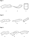
- the Figure 1 shows schematically the possibilities for different coating of surfaces.
- the path of travel of the coating head (shown by the continuous arrow (-)) in these examples a) - c) moves parallel to the curvature of the surface of the workpiece (shown by the broken arrow (- - - -)).
- Curved surfaces are generally understood to mean those surfaces that can be rolled off. These are characterized by the fact that concave and / or convex curvatures only lie in the longitudinal or transverse direction to the travel path of the printing unit and a straight line can be described for each point on the plane, which runs orthogonally to the course of the curvature.
- the Figure 2 shows schematically the possibilities for different coating of surfaces.
- the path of travel of the coating head (shown by the solid arrow (-)) in these examples a) - c) is offset by 90 ° to the curvature of the surface of the workpiece (shown by the broken arrow (- - - -)).
- the Figure 3 shows schematically the possibilities for different coating of surfaces.
- the surface of the workpiece has curvatures in more than one direction (shown by the broken arrows (- - - -)). This means that the surface is distorted.
- the distorted surfaces differ from the curved surfaces in that they cannot be developed.
- films to be applied would have to be stretched, stretched or compressed in some areas.
- the travel path of the coating head (shown by the continuous arrow (-)) cannot always run symmetrically to the curvature on this workpiece surface and, with constant directions of movement of the coating head, workpiece surface areas with a significantly different angular orientation towards the coating head are traversed. In addition to the angular deviations, with a constant direction of movement of the coating head, various stretches on the workpiece surface are covered.
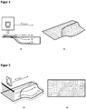
- the Figure 4 and Figure 5 show examples of different movement paths of different coating nozzles (V1-V3) of an inkjet head on an underlying concave and convex distorted surface a).
- the corresponding grid projection is shown in the respective figures b).
- the different alignment of the respective nozzle to the underlying surface has a direct influence on the distances that the nozzles cover on the underlying surface with constant movement of the printing unit. This results from the rigid coating head surface that cannot be adapted to the surface.
- the mode of operation of the print head is to be understood as 2-dimensional, regardless of the fact that the surface and / or the coating unit can execute a relative movement with up to 6 degrees of freedom via the actuators. This relative movement serves to deliver the printing unit as parallel as possible to each surface position. Since the image data are only stored in two dimensions, other additional data relating to the path, such as angular deviation and distance differences, must already be taken into account in the image data.
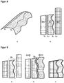
- the Figure 6 shows an exemplary representation for obtaining the angular deviation between the normal vectors of the travel path (vectors with the index P) and the associated normal vector of the grid area on the surface (vectors with the index S).
- collinear normal vectors there is no angular deviation between the two normal vectors.
- the normal vector of the printing plane is a multiple of the normal vector of the relevant raster area.
- the angular deviation of the two normal vectors in both the X and Y directions is zero. If the surface is curved, the normal vectors are no longer collinear but, depending on the alignment between the workpiece surface and the travel path, there are angular deviations in the X and / or Y directions ( ⁇ (x), ⁇ (y)).
- the Figure 7 shows a possibility of dividing bidirectionally curved surfaces into travel and pressure paths. It is shown that the individual travel paths overlap on the surface (S1, S2), ie that individual workpiece surface areas can in principle be coated over several travel paths. As a function of the curvature of the surface, it can be useful to choose different coating areas (printing paths) for each travel path. It is thus possible that the constantly curved (planar) left area is coated by a printing path that corresponds to the maximum possible travel path (large coating area per travel path). However, if the trajectory sweeps over an area with strong curvatures (middle head), it can be beneficial to select a small print area under this trajectory in order not to let the angular deviations of the surface per trajectory become too large. In comparison to the left-hand travel path, this is indicated by the smaller horizontal line.
- the Figure 8 shows pressure paths as a sub-area of travel paths on a complex workpiece surface.
- the edges of the print webs at which they meet are called cutting lines.
- the so-called stitching the pressure paths can be placed hard against each other or each other overlap running out. With the stitching it is possible to hide the transitions between the print webs further via the print system control so that these cut areas cannot be recognized in later decors. Particularly in the case of non-parallel print paths, it should be noted that the travel paths have different angles to the surface of the cutting area below.
- Adjacent print webs with complementary cutting lines are understood to mean all adjacent print webs in which the projections of the cut lines on the respective print web are complementary to the projection of the same cut line on the respective adjacent print web.
- parallel paths that is, those that differ only in terms of X and Y alignment, as well as cutting lines that run constantly straight along the X axis, can be counted as "neighboring printing paths with complementary cutting lines".
- other constellations are also conceivable.
- the alignment of the print head has a significant influence on the 2-dimensional projection of the cutting line, which defines the frame for the image data of the respective print path.
- the projection length of the cutting line can thus change, as a result of which it may be necessary to adapt the image data of one or both of the adjacent tracks in order to harmonize them.
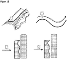
- the Figure 11 shows schematically possible deviations between a target and an actual travel path, as well as the results of the respective grid projections on the target and the actual travel path.
- the target black solid arrows
- the actual dashed arrows
- Both traverse paths differ from one another at least in the swept surface of the workpiece and, as a result of the curvature of the workpiece, also in the alignment between the surface and the print head.
- the results of the grid projections are shown for the respective target (black solid arrow) and the actual travel paths (dashed arrow) in the two lower figures.
- the basis for the differences between the target and actual travel path lies mainly in the regulation and / or control process to be used.
Landscapes
- Engineering & Computer Science (AREA)
- Robotics (AREA)
- Mechanical Engineering (AREA)
- Manufacturing & Machinery (AREA)
- Application Of Or Painting With Fluid Materials (AREA)
Applications Claiming Priority (1)
| Application Number | Priority Date | Filing Date | Title |
|---|---|---|---|
| DE102020105704.0A DE102020105704A1 (de) | 2020-03-03 | 2020-03-03 | Verfahren zur digitalen Beschichtung dreidimensionaler Werkstückoberflächen |
Publications (3)
| Publication Number | Publication Date |
|---|---|
| EP3875280A1 true EP3875280A1 (fr) | 2021-09-08 |
| EP3875280C0 EP3875280C0 (fr) | 2024-08-28 |
| EP3875280B1 EP3875280B1 (fr) | 2024-08-28 |
Family
ID=74856645
Family Applications (1)
| Application Number | Title | Priority Date | Filing Date |
|---|---|---|---|
| EP21160259.4A Active EP3875280B1 (fr) | 2020-03-03 | 2021-03-02 | Procédé de revêtement numérique des surfaces de pièces tridimensionnelles |
Country Status (2)
| Country | Link |
|---|---|
| EP (1) | EP3875280B1 (fr) |
| DE (1) | DE102020105704A1 (fr) |
Cited By (6)
| Publication number | Priority date | Publication date | Assignee | Title |
|---|---|---|---|---|
| CN115106542A (zh) * | 2022-08-29 | 2022-09-27 | 芯体素(杭州)科技发展有限公司 | 一种高效精密电子直写三维打印路径规划方法 |
| CN115891474A (zh) * | 2021-09-30 | 2023-04-04 | 细美事有限公司 | 确定印刷路径的方法、用于执行确定印刷路径的方法的程序及印刷方法 |
| WO2024139838A1 (fr) * | 2022-12-30 | 2024-07-04 | 华为技术有限公司 | Dispositif électronique et procédé de revêtement de matériau |
| CN118876436A (zh) * | 2024-09-26 | 2024-11-01 | 北京阿迈特医疗器械有限公司 | 植、介入性器械的打印调控方法、装置及植、介入性器械 |
| CN119408324A (zh) * | 2024-09-26 | 2025-02-11 | 深圳市毕昇精一技术有限公司 | 异型产品的表面喷印方法、装置及系统 |
| CN121468593A (zh) * | 2026-01-07 | 2026-02-06 | 张家港梦康生活家居科技有限公司 | 一种用于脱模剂喷涂的机械臂控制方法 |
Citations (10)
| Publication number | Priority date | Publication date | Assignee | Title |
|---|---|---|---|---|
| US5436027A (en) * | 1993-12-23 | 1995-07-25 | The Boeing Company | Method of applying a coating design |
| US20090169719A1 (en) * | 2007-12-31 | 2009-07-02 | Exatec Llc | Method for printing high quality images on curved substrates |
| EP2287722A1 (fr) * | 2008-11-28 | 2011-02-23 | Mimaki Engineering Co., Ltd. | Dispositif de génération de données d'impression, procédé de génération de données d'impression, et programme de génération de données d'impression |
| DE102010004496A1 (de) * | 2010-01-12 | 2011-07-14 | Müller, Hermann, 88279 | Verfahren zum Betrieb einer Vorrichtung zum Beschichten und/oder Bedrucken eines Werkstückes |
| EP2838708A2 (fr) | 2012-07-19 | 2015-02-25 | NIKE Innovate C.V. | Impression directe sur tissu |
| US20150062244A1 (en) * | 2013-08-30 | 2015-03-05 | Heidelberger Druckmaschinen Ag | Method and apparatus for producing a relative movement between a jet unit and a curved surface |
| US20170232733A1 (en) * | 2016-02-17 | 2017-08-17 | Heidelberger Druckmaschinen Ag | Method for inkjet printing on at least one curved region of a surface of an object and device for implementing the method |
| US9878533B2 (en) * | 2014-12-09 | 2018-01-30 | Krones Ag | Method and device for ink-jet printing onto containers |
| US20190091712A1 (en) * | 2016-03-04 | 2019-03-28 | Exel Industries | Applicator of coating product, multiaxis robot comprising such an applicator and application method of a coating product |
| DE102018121557A1 (de) | 2018-09-04 | 2020-03-05 | ISP GmbH & Co. KG | Verfahren zur verzerrungsfreien Beschichtung von Werkstücken mit bidirektional gekrümmten Oberflächen |
Family Cites Families (1)
| Publication number | Priority date | Publication date | Assignee | Title |
|---|---|---|---|---|
| EP2229282A1 (fr) | 2007-12-31 | 2010-09-22 | Exatec, LLC. | Appareil et procédé pour imprimer des articles tridimensionnels |
-
2020
- 2020-03-03 DE DE102020105704.0A patent/DE102020105704A1/de not_active Withdrawn
-
2021
- 2021-03-02 EP EP21160259.4A patent/EP3875280B1/fr active Active
Patent Citations (10)
| Publication number | Priority date | Publication date | Assignee | Title |
|---|---|---|---|---|
| US5436027A (en) * | 1993-12-23 | 1995-07-25 | The Boeing Company | Method of applying a coating design |
| US20090169719A1 (en) * | 2007-12-31 | 2009-07-02 | Exatec Llc | Method for printing high quality images on curved substrates |
| EP2287722A1 (fr) * | 2008-11-28 | 2011-02-23 | Mimaki Engineering Co., Ltd. | Dispositif de génération de données d'impression, procédé de génération de données d'impression, et programme de génération de données d'impression |
| DE102010004496A1 (de) * | 2010-01-12 | 2011-07-14 | Müller, Hermann, 88279 | Verfahren zum Betrieb einer Vorrichtung zum Beschichten und/oder Bedrucken eines Werkstückes |
| EP2838708A2 (fr) | 2012-07-19 | 2015-02-25 | NIKE Innovate C.V. | Impression directe sur tissu |
| US20150062244A1 (en) * | 2013-08-30 | 2015-03-05 | Heidelberger Druckmaschinen Ag | Method and apparatus for producing a relative movement between a jet unit and a curved surface |
| US9878533B2 (en) * | 2014-12-09 | 2018-01-30 | Krones Ag | Method and device for ink-jet printing onto containers |
| US20170232733A1 (en) * | 2016-02-17 | 2017-08-17 | Heidelberger Druckmaschinen Ag | Method for inkjet printing on at least one curved region of a surface of an object and device for implementing the method |
| US20190091712A1 (en) * | 2016-03-04 | 2019-03-28 | Exel Industries | Applicator of coating product, multiaxis robot comprising such an applicator and application method of a coating product |
| DE102018121557A1 (de) | 2018-09-04 | 2020-03-05 | ISP GmbH & Co. KG | Verfahren zur verzerrungsfreien Beschichtung von Werkstücken mit bidirektional gekrümmten Oberflächen |
Cited By (6)
| Publication number | Priority date | Publication date | Assignee | Title |
|---|---|---|---|---|
| CN115891474A (zh) * | 2021-09-30 | 2023-04-04 | 细美事有限公司 | 确定印刷路径的方法、用于执行确定印刷路径的方法的程序及印刷方法 |
| CN115106542A (zh) * | 2022-08-29 | 2022-09-27 | 芯体素(杭州)科技发展有限公司 | 一种高效精密电子直写三维打印路径规划方法 |
| WO2024139838A1 (fr) * | 2022-12-30 | 2024-07-04 | 华为技术有限公司 | Dispositif électronique et procédé de revêtement de matériau |
| CN118876436A (zh) * | 2024-09-26 | 2024-11-01 | 北京阿迈特医疗器械有限公司 | 植、介入性器械的打印调控方法、装置及植、介入性器械 |
| CN119408324A (zh) * | 2024-09-26 | 2025-02-11 | 深圳市毕昇精一技术有限公司 | 异型产品的表面喷印方法、装置及系统 |
| CN121468593A (zh) * | 2026-01-07 | 2026-02-06 | 张家港梦康生活家居科技有限公司 | 一种用于脱模剂喷涂的机械臂控制方法 |
Also Published As
| Publication number | Publication date |
|---|---|
| EP3875280C0 (fr) | 2024-08-28 |
| EP3875280B1 (fr) | 2024-08-28 |
| DE102020105704A1 (de) | 2021-09-09 |
Similar Documents
| Publication | Publication Date | Title |
|---|---|---|
| EP3875280B1 (fr) | Procédé de revêtement numérique des surfaces de pièces tridimensionnelles | |
| EP3208746B1 (fr) | Procédé d'impression par jet d'encre d'au moins une zone courbée de la surface d'un objet | |
| EP3781406B1 (fr) | Revêtement de surfaces par goutte à la demande | |
| EP2644392B1 (fr) | Système destiné à imprimer un objet | |
| EP3847029B1 (fr) | Revêtement sans déformation de surfaces intérieures de véhicule | |
| DE102017114280B4 (de) | Verfahren zum Bedrucken einer gekrümmten Oberfläche sowie Vorrichtung zum Bedrucken dreidimensionaler Oberflächen | |
| EP3002128B1 (fr) | Procede d'impression d'une surface courbee d'un objet a l'aide d'une tete d'impression a jet d'encre | |
| DE102009021608B4 (de) | Einrichtung und Verfahren zum Lackieren gekrümmter Außenoberflächen eines Luftfahrzeuges | |
| EP1990206B1 (fr) | Procédé et dispositif d'impression d'un composant ayant deux zones de surface inclinées l'une vers l'autre à l'aide d'un procédé d'impression numérique | |
| DE102014011301A1 (de) | Verfahren zum Erzeugen einer Relativbewegung zwischen einer Strahleinheit und einer gekrümmten Oberfläche | |
| DE102014221103A1 (de) | Verfahren zum Erzeugen eines Aufdrucks auf einem Objekt mit einer gekrümmten Oberfläche | |
| DE102009004878A1 (de) | Verfahren zum Beschichten, insbesondere Lackieren, einer Oberfläche sowie digitales Beschichtungssystem | |
| EP3847028B1 (fr) | Procédé de revêtement sans déformation et homogène de pièces ouvrées ayant des surfaces bidirectionnellement courbes | |
| EP1839884B1 (fr) | Dispositif d'impression aux contours exacts d'images décoratives sur des pièces usinées plates | |
| DE102015205631B4 (de) | Verfahren zum automatisierten Bedrucken einer gekrümmten Oberfläche eines dreidimensionalen Objekts | |
| DE102020127852A1 (de) | Betriebsverfahren für eine Beschichtungsanlage und entsprechend angepasste Beschichtungsanlage | |
| DE102015225957A1 (de) | Verfahren zum Bedrucken eines Objekts | |
| DE102021108563A1 (de) | Bahnkorrekturverfahren für eine Beschichtungsanlage | |
| DE102020105702A1 (de) | Verfahren zur Funktionalisierung von Werkstückoberflächen mittels eines digitalen Beschichtungsverfahrens | |
| WO2020048969A1 (fr) | Composant 3d pourvu d'une décoration passant sans déformation sur une surface | |
| EP3547221B1 (fr) | Procédé d'impression de la surface d'un objet | |
| DE102016013319A1 (de) | Vorrichtung und Verfahren zum Aufbringen von fließfähigem Material auf eine um eine Drehachse drehbare Unterlage | |
| DE102019004784A1 (de) | Verfahren zum Drucken eines Bilds auf eine dreidimensionale Freiformfläche, sowie Vorrichtung, eingerichtet zum Durchführen eines solchen Verfahrens | |
| DE102019119730B4 (de) | Applikator zum Drucken von Mustern und Verfahren hierfür | |
| AT522737B1 (de) | Verfahren zum digitalen Bedrucken einer Profilleiste |
Legal Events
| Date | Code | Title | Description |
|---|---|---|---|
| PUAI | Public reference made under article 153(3) epc to a published international application that has entered the european phase |
Free format text: ORIGINAL CODE: 0009012 |
|
| STAA | Information on the status of an ep patent application or granted ep patent |
Free format text: STATUS: THE APPLICATION HAS BEEN PUBLISHED |
|
| AK | Designated contracting states |
Kind code of ref document: A1 Designated state(s): AL AT BE BG CH CY CZ DE DK EE ES FI FR GB GR HR HU IE IS IT LI LT LU LV MC MK MT NL NO PL PT RO RS SE SI SK SM TR |
|
| STAA | Information on the status of an ep patent application or granted ep patent |
Free format text: STATUS: REQUEST FOR EXAMINATION WAS MADE |
|
| 17P | Request for examination filed |
Effective date: 20220224 |
|
| RBV | Designated contracting states (corrected) |
Designated state(s): AL AT BE BG CH CY CZ DE DK EE ES FI FR GB GR HR HU IE IS IT LI LT LU LV MC MK MT NL NO PL PT RO RS SE SI SK SM TR |
|
| GRAP | Despatch of communication of intention to grant a patent |
Free format text: ORIGINAL CODE: EPIDOSNIGR1 |
|
| STAA | Information on the status of an ep patent application or granted ep patent |
Free format text: STATUS: GRANT OF PATENT IS INTENDED |
|
| INTG | Intention to grant announced |
Effective date: 20240321 |
|
| RIC1 | Information provided on ipc code assigned before grant |
Ipc: B25J 11/00 20060101ALI20240308BHEP Ipc: B41J 3/407 20060101AFI20240308BHEP |
|
| GRAS | Grant fee paid |
Free format text: ORIGINAL CODE: EPIDOSNIGR3 |
|
| GRAA | (expected) grant |
Free format text: ORIGINAL CODE: 0009210 |
|
| STAA | Information on the status of an ep patent application or granted ep patent |
Free format text: STATUS: THE PATENT HAS BEEN GRANTED |
|
| AK | Designated contracting states |
Kind code of ref document: B1 Designated state(s): AL AT BE BG CH CY CZ DE DK EE ES FI FR GB GR HR HU IE IS IT LI LT LU LV MC MK MT NL NO PL PT RO RS SE SI SK SM TR |
|
| REG | Reference to a national code |
Ref country code: CH Ref legal event code: EP |
|
| REG | Reference to a national code |
Ref country code: DE Ref legal event code: R096 Ref document number: 502021004911 Country of ref document: DE |
|
| REG | Reference to a national code |
Ref country code: IE Ref legal event code: FG4D Free format text: LANGUAGE OF EP DOCUMENT: GERMAN |
|
| U01 | Request for unitary effect filed |
Effective date: 20240924 |
|
| U07 | Unitary effect registered |
Designated state(s): AT BE BG DE DK EE FI FR IT LT LU LV MT NL PT RO SE SI Effective date: 20241016 |
|
| PG25 | Lapsed in a contracting state [announced via postgrant information from national office to epo] |
Ref country code: NO Free format text: LAPSE BECAUSE OF FAILURE TO SUBMIT A TRANSLATION OF THE DESCRIPTION OR TO PAY THE FEE WITHIN THE PRESCRIBED TIME-LIMIT Effective date: 20241128 |
|
| PG25 | Lapsed in a contracting state [announced via postgrant information from national office to epo] |
Ref country code: GR Free format text: LAPSE BECAUSE OF FAILURE TO SUBMIT A TRANSLATION OF THE DESCRIPTION OR TO PAY THE FEE WITHIN THE PRESCRIBED TIME-LIMIT Effective date: 20241129 Ref country code: PL Free format text: LAPSE BECAUSE OF FAILURE TO SUBMIT A TRANSLATION OF THE DESCRIPTION OR TO PAY THE FEE WITHIN THE PRESCRIBED TIME-LIMIT Effective date: 20240828 |
|
| PG25 | Lapsed in a contracting state [announced via postgrant information from national office to epo] |
Ref country code: IS Free format text: LAPSE BECAUSE OF FAILURE TO SUBMIT A TRANSLATION OF THE DESCRIPTION OR TO PAY THE FEE WITHIN THE PRESCRIBED TIME-LIMIT Effective date: 20241228 |
|
| PG25 | Lapsed in a contracting state [announced via postgrant information from national office to epo] |
Ref country code: HR Free format text: LAPSE BECAUSE OF FAILURE TO SUBMIT A TRANSLATION OF THE DESCRIPTION OR TO PAY THE FEE WITHIN THE PRESCRIBED TIME-LIMIT Effective date: 20240828 |
|
| PG25 | Lapsed in a contracting state [announced via postgrant information from national office to epo] |
Ref country code: RS Free format text: LAPSE BECAUSE OF FAILURE TO SUBMIT A TRANSLATION OF THE DESCRIPTION OR TO PAY THE FEE WITHIN THE PRESCRIBED TIME-LIMIT Effective date: 20241128 Ref country code: ES Free format text: LAPSE BECAUSE OF FAILURE TO SUBMIT A TRANSLATION OF THE DESCRIPTION OR TO PAY THE FEE WITHIN THE PRESCRIBED TIME-LIMIT Effective date: 20240828 |
|
| PG25 | Lapsed in a contracting state [announced via postgrant information from national office to epo] |
Ref country code: RS Free format text: LAPSE BECAUSE OF FAILURE TO SUBMIT A TRANSLATION OF THE DESCRIPTION OR TO PAY THE FEE WITHIN THE PRESCRIBED TIME-LIMIT Effective date: 20241128 Ref country code: PL Free format text: LAPSE BECAUSE OF FAILURE TO SUBMIT A TRANSLATION OF THE DESCRIPTION OR TO PAY THE FEE WITHIN THE PRESCRIBED TIME-LIMIT Effective date: 20240828 Ref country code: NO Free format text: LAPSE BECAUSE OF FAILURE TO SUBMIT A TRANSLATION OF THE DESCRIPTION OR TO PAY THE FEE WITHIN THE PRESCRIBED TIME-LIMIT Effective date: 20241128 Ref country code: IS Free format text: LAPSE BECAUSE OF FAILURE TO SUBMIT A TRANSLATION OF THE DESCRIPTION OR TO PAY THE FEE WITHIN THE PRESCRIBED TIME-LIMIT Effective date: 20241228 Ref country code: HR Free format text: LAPSE BECAUSE OF FAILURE TO SUBMIT A TRANSLATION OF THE DESCRIPTION OR TO PAY THE FEE WITHIN THE PRESCRIBED TIME-LIMIT Effective date: 20240828 Ref country code: GR Free format text: LAPSE BECAUSE OF FAILURE TO SUBMIT A TRANSLATION OF THE DESCRIPTION OR TO PAY THE FEE WITHIN THE PRESCRIBED TIME-LIMIT Effective date: 20241129 Ref country code: ES Free format text: LAPSE BECAUSE OF FAILURE TO SUBMIT A TRANSLATION OF THE DESCRIPTION OR TO PAY THE FEE WITHIN THE PRESCRIBED TIME-LIMIT Effective date: 20240828 |
|
| U20 | Renewal fee for the european patent with unitary effect paid |
Year of fee payment: 5 Effective date: 20250305 |
|
| PG25 | Lapsed in a contracting state [announced via postgrant information from national office to epo] |
Ref country code: SM Free format text: LAPSE BECAUSE OF FAILURE TO SUBMIT A TRANSLATION OF THE DESCRIPTION OR TO PAY THE FEE WITHIN THE PRESCRIBED TIME-LIMIT Effective date: 20240828 |
|
| PG25 | Lapsed in a contracting state [announced via postgrant information from national office to epo] |
Ref country code: CZ Free format text: LAPSE BECAUSE OF FAILURE TO SUBMIT A TRANSLATION OF THE DESCRIPTION OR TO PAY THE FEE WITHIN THE PRESCRIBED TIME-LIMIT Effective date: 20240828 |
|
| PG25 | Lapsed in a contracting state [announced via postgrant information from national office to epo] |
Ref country code: SK Free format text: LAPSE BECAUSE OF FAILURE TO SUBMIT A TRANSLATION OF THE DESCRIPTION OR TO PAY THE FEE WITHIN THE PRESCRIBED TIME-LIMIT Effective date: 20240828 |
|
| PLBE | No opposition filed within time limit |
Free format text: ORIGINAL CODE: 0009261 |
|
| STAA | Information on the status of an ep patent application or granted ep patent |
Free format text: STATUS: NO OPPOSITION FILED WITHIN TIME LIMIT |
|
| 26N | No opposition filed |
Effective date: 20250530 |
|
| PG25 | Lapsed in a contracting state [announced via postgrant information from national office to epo] |
Ref country code: MC Free format text: LAPSE BECAUSE OF FAILURE TO SUBMIT A TRANSLATION OF THE DESCRIPTION OR TO PAY THE FEE WITHIN THE PRESCRIBED TIME-LIMIT Effective date: 20240828 |
|
| REG | Reference to a national code |
Ref country code: CH Ref legal event code: H13 Free format text: ST27 STATUS EVENT CODE: U-0-0-H10-H13 (AS PROVIDED BY THE NATIONAL OFFICE) Effective date: 20251024 |
|
| GBPC | Gb: european patent ceased through non-payment of renewal fee |
Effective date: 20250302 |
|
| PG25 | Lapsed in a contracting state [announced via postgrant information from national office to epo] |
Ref country code: GB Free format text: LAPSE BECAUSE OF NON-PAYMENT OF DUE FEES Effective date: 20250302 |
|
| PG25 | Lapsed in a contracting state [announced via postgrant information from national office to epo] |
Ref country code: CH Free format text: LAPSE BECAUSE OF NON-PAYMENT OF DUE FEES Effective date: 20250331 |
|
| PG25 | Lapsed in a contracting state [announced via postgrant information from national office to epo] |
Ref country code: IE Free format text: LAPSE BECAUSE OF NON-PAYMENT OF DUE FEES Effective date: 20250302 |
|
| U20 | Renewal fee for the european patent with unitary effect paid |
Year of fee payment: 6 Effective date: 20260304 |