EP3875341A1 - Châssis de train de marchandises et train de marchandises - Google Patents
Châssis de train de marchandises et train de marchandises Download PDFInfo
- Publication number
- EP3875341A1 EP3875341A1 EP18925721.5A EP18925721A EP3875341A1 EP 3875341 A1 EP3875341 A1 EP 3875341A1 EP 18925721 A EP18925721 A EP 18925721A EP 3875341 A1 EP3875341 A1 EP 3875341A1
- Authority
- EP
- European Patent Office
- Prior art keywords
- chassis
- freight train
- connecting member
- module
- chassis module
- Prior art date
- Legal status (The legal status is an assumption and is not a legal conclusion. Google has not performed a legal analysis and makes no representation as to the accuracy of the status listed.)
- Granted
Links
Images



Classifications
-
- B—PERFORMING OPERATIONS; TRANSPORTING
- B61—RAILWAYS
- B61D—BODY DETAILS OR KINDS OF RAILWAY VEHICLES
- B61D3/00—Wagons or vans
- B61D3/005—Wagons or vans convertible
-
- B—PERFORMING OPERATIONS; TRANSPORTING
- B61—RAILWAYS
- B61D—BODY DETAILS OR KINDS OF RAILWAY VEHICLES
- B61D3/00—Wagons or vans
- B61D3/16—Wagons or vans adapted for carrying special loads
- B61D3/20—Wagons or vans adapted for carrying special loads for forwarding containers
-
- B—PERFORMING OPERATIONS; TRANSPORTING
- B61—RAILWAYS
- B61D—BODY DETAILS OR KINDS OF RAILWAY VEHICLES
- B61D45/00—Means or devices for securing or supporting the cargo, including protection against shocks
- B61D45/007—Fixing containers
-
- B—PERFORMING OPERATIONS; TRANSPORTING
- B61—RAILWAYS
- B61F—RAIL VEHICLE SUSPENSIONS, e.g. UNDERFRAMES, BOGIES OR ARRANGEMENTS OF WHEEL AXLES; RAIL VEHICLES FOR USE ON TRACKS OF DIFFERENT WIDTH; PREVENTING DERAILING OF RAIL VEHICLES; WHEEL GUARDS, OBSTRUCTION REMOVERS OR THE LIKE FOR RAIL VEHICLES
- B61F1/00—Underframes
Definitions
- the present invention relates to a technical field of freight train, in particular, to a freight train chassis and a freight train.
- the vehicle chassis of the freight train mainly adopts the welded overall structure, and the size of the vehicle chassis is mainly manufactured according to relevant standard rules.
- the size of the vehicle chassis of the freight train is fixed after the production of the vehicle chassis is completed.
- the invention provides a freight train chassis and a freight train to solve the problem in the prior art that, when the transportation is performed using the freight train with the fixed size chassis for different sizes of containers, the space thereof cannot be effectively utilized and the railway transportation efficiency and the transportation volume thereof are affected.
- the freight train chassis and the freight train provided by the invention improve the adaptability of the freight train to different sizes of goods and the space utilization rate of the freight train, and improve the transportation efficiency and transportation volume of railway transportation.
- the present invention provides a freight train chassis, including: a first chassis module, a plurality of connecting modules and at least one second chassis module, where the first chassis module and the second chassis module are disposed along a length direction of a freight train, the second chassis module is connected to the first chassis module by one or more connecting modules of the plurality of connecting modules, and the second chassis modules are connected by one or more connecting modules of the plurality of connecting modules.
- the present invention provides a freight train chassis, the second chassis module is connected to the first chassis module by at least two of the plurality of connecting modules, and the second chassis modules are connected by at least two of the plurality of connecting modules.
- the present invention provides a freight train chassis
- the connecting module includes a first connecting member, a second connecting member, a connecting shaft and a tensioner, where a profile hole matching the tensioner is disposed on the first connecting member and a circular hole is disposed on the second connecting member, the connecting shaft passes through the profile hole and the circular hole to connect the first connecting member and the second connecting member, the tensioner is used to be inserted into the profile hole and abutted against the connecting shaft, so that the first connecting member is rigidly connected with the second connecting member; and the first connecting member and/or the second connecting member are connected to the first chassis module; and the first connecting member and/or the second connecting member are connected to the second chassis module.
- the present invention provides a freight train chassis, the tensioner is a wedge block, the connecting shaft has a slope matching the wedge block, and when the tensioner is inserted into the profile hole, the wedge block is abutted against the slope; and both of the number of the slope and the number of the wedge block are at least two, and the two slopes are respectively located on two ends of the connecting shaft or are respectively located on opposite sides of a same end of the connecting shaft.
- the present invention provides a freight train chassis, the connecting module further includes an adjusting plate, and the adjusting plate has an adjustable thickness, the adjusting plate is used to be abutted against the second connecting member when the tensioner is inserted into the profile hole.
- the present invention provides a freight train chassis, the number of the adjusting plate is plural, and the plurality of adjusting plates have different thicknesses, and one of the adjusting plates is selected to be detachably connected to the first connecting member.
- the present invention provides a freight train chassis, the first connecting member has a U-shaped groove, the U-shaped groove is disposed along the length direction of the freight train, an opening direction of the U-shaped groove is perpendicular to an axis of the profile hole, the U-shaped groove is in communication with the profile hole, the second connecting member is inserted into the U-shaped groove, and the connecting shaft sequentially passes through the profile hole on one side of the U-shaped groove, the circular hole and the profile hole on the other side of the U-shaped groove to connect the first connecting member and the second connecting member.
- the present invention provides a freight train chassis, and the adjusting plate is located at a bottom of the U-shaped groove.
- the present invention provides a freight train chassis
- the first chassis module includes two side beams, a sleeper beam, an end beam and at least one first crossbeam, and the two side beams are oppositely disposed parallel to the length direction of the freight train; and the sleeper beam, the end beam and the at least one first crossbeam are located between the two side beams, and two ends of the sleeper beam are respectively connected to the two side beams, two ends of the end beam are respectively connected to the two side beams, and two ends of the at least one first crossbeam are respectively connected to the two side beams.
- the present invention provides a freight train chassis, the first connecting member and/or the second connecting member are located on end surfaces of the two side beams perpendicular to the length direction of the freight train, and is connected to one end of the two side beams which is connected to the second chassis module.
- the present invention provides a freight train chassis, a thickness of one end of each side beam of the side beams which is not connected to the second chassis module in a vertical direction is smaller than a thickness of one end of the side beam which is connected to the second chassis module in the vertical direction.
- the present invention provides a freight train chassis
- the second chassis module includes two boundary beams and a plurality of second crossbeams; the two boundary beams are disposed opposite to each other in a direction parallel to the length direction of the freight train, and the plurality of second crossbeams are disposed between the two boundary beams and are connected to sides, opposite to each other, of the two boundary beams.
- the present invention provides a freight train chassis, and the first connecting member and/or the second connecting member are located on end surfaces of the two boundary beams perpendicular to the length direction of the freight train.
- the present invention provides a freight train chassis, a thickness of each boundary beam of the boundary beams in a vertical direction is equal to the thickness of one end of the crossbeam which is connected to the second chassis module in the vertical direction.
- the present invention provides a freight train chassis, and both the side beams and the boundary beams are -shaped steel or H-shaped steel.
- the present invention provides a freight train chassis.
- the freight train chassis further includes a locking member, the number of the locking member is plural, and both the first chassis module and the second chassis module are provided with the locking members, and the locking members are used to fix goods.
- the present invention provides a freight train.
- the freight train includes the freight train chassis of the first aspect of the present invention.
- the present invention provides a freight train.
- the freight train further includes a coupler buffer device, where the coupler buffer device is disposed on the first chassis module.
- the present invention provides a freight train.
- the freight train further includes a bogie, where the bogie is connected to a bottom of the first chassis module.
- the present invention provides a freight train.
- the freight train further includes an upper center plate, disposed at the bottom of the first chassis module, where the upper center plate is used to connect to the bogie and the first chassis module.
- the freight train chassis and the freight train provided by the present invention provide a first chassis module, a plurality of connecting modules and at least one second chassis module, where the first chassis module and the second chassis module are disposed along a length direction of a freight train, the second chassis module is connected to the first chassis module by the connecting module, and the second chassis modules are connected by the connecting module.
- the number of the second chassis module can be adjusted as required for different sizes of goods or containers, thereby adjusting the length of the freight train chassis, which improves the adaptability of the freight train to different sizes of goods and the space utilization rate of the freight train, and improves the transportation efficiency and transportation volume of railway transportation.
- the vehicle chassis of the freight train mainly adopts the welded overall structure, and the size of the vehicle chassis is mainly manufactured according to relevant standard rules.
- the size of the vehicle chassis of the freight train is fixed after the production of the vehicle chassis is completed.
- FIG. 1 is a schematic view showing an overall structure of a freight train chassis provided by the present invention.
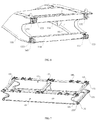
- FIG. 2a is a schematic view of a structure of a freight train chassis connected with a plurality of second chassis modules provided by the present invention.
- FIG. 2b is a schematic view of a structure of a freight train chassis connected with a single second chassis module provided by the present invention.
- FIG. 2c is a schematic view of a structure of a freight train chassis not connected with a second chassis module provided by the present invention.
- FIG. 3 is a schematic view showing an overall structure of a connecting module of the freight train chassis provided by the present invention.
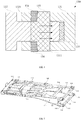
- FIG. 4 is a cross-sectional view of a connecting module of a freight train chassis provided by the present invention.
- FIG. 5 is a schematic view of a structure of a first chassis module of a freight train chassis provided by the present invention.
- FIG. 6 is a partial enlarged view of one end of a first chassis module of a freight train chassis connected to a second chassis module provided by the present invention.
- FIG. 7 is a schematic view showing an overall structure of a second chassis module of a freight train chassis provided by the present invention.
- the freight train chassis 1 includes a first chassis module 110, a plurality of connecting modules 130 and at least one second chassis module 120.
- the first chassis module 110 and the second chassis module 120 are disposed along a length direction of a freight train, the second chassis module 120 is connected to the first chassis module 110 by the connecting module 130, and the second chassis modules 120 are connected by the connecting module 130.
- a first chassis module, a plurality of connecting modules and at least one second chassis module are provided, where the first chassis module and the second chassis module are disposed along a length direction of the freight train, the second chassis module is connected to the first chassis module by the connecting modules, and the second chassis modules are connected by the connecting modules.
- the number of the second chassis module can be adjusted according to the needs of different sizes of goods or containers, thereby adjusting the length of the freight train chassis, which improves the adaptability of the freight train to different sizes of goods and the space utilization rate of the freight train, and improves the transportation efficiency and transportation volume of railway transportation.
- FIG. 2a is a schematic view of a structure of a freight train chassis connected with a plurality of second chassis modules provided by the present invention
- FIG. 2b is a schematic view of a structure of a freight train chassis connected with a single second chassis module provided by the present invention
- FIG. 2c is a schematic view of a structure of a freight train chassis not connected with a second chassis module provided by the present invention.
- the plurality of second chassis modules 120 are connected to each other through the connection module 130, then, they are connected to the first chassis module 110 through the connection module 130.
- the length of the freight train chassis 1 can be adjusted to accommodate different sizes and lengths of goods.
- the freight train chassis 1 provided in the present embodiment may comprise only two first chassis modules 110 connected through the connecting module 130. In this way, in the case that the length of the train chassis is fixed, for the small-sized goods, the space of the train chassis is too large, space waste is avoided, and the space utilization rate of the freight train and the transportation volume of the freight train are improved.
- the second chassis module 120 is connected to the first chassis module 110 by at least two connecting modules 130, and the second chassis modules 120 are connected by the at least two connecting modules 130.
- the at least two connecting modules 130 may be disposed on an end surface of the second chassis module 120 perpendicular to the length direction of the freight train, and the at least two connecting modules 130 may be disposed in parallel with each other on the end surface of the second chassis module 120, and the at least two connecting modules 130 may also be disposed at opposite corners of the end surface of the second chassis module 120.
- the connecting module 130 is connected to the first chassis module 110.
- the connecting module 130 may also be disposed on the end surface of the first chassis module 110 perpendicular to the length direction of the freight train, and the connecting module 130 is connected to the second chassis module 120.
- four connecting modules 130 may be set, and the four connecting modules 130 are disposed on four corners of the end surface of the second connecting module 120 perpendicular to the length direction of the freight train; or, the four connecting modules 130 are disposed on four corners of the end surface of the first connecting module 110 perpendicular to the length direction of the freight train.
- the number of the connecting module is set to four, which increases the rigidity and stability of the connection surface, improves the rigidity of the overall vertical direction of the frame, and further increases the bearing capacity of the freight train chassis.
- the connecting module 130 includes a first connecting member 131, a second connecting member 132, a connecting shaft 133 and a tensioner 134, where a profile hole 1311 matching the tensioner 134 is disposed on the first connecting member 131, a circular hole 1321 is disposed on the second connecting member 132, the connecting shaft 133 passes through the profile hole 1311 and the circular hole 1321 to connect the first connecting member 131 and the second connecting member 132, and the tensioner 134 is used to be inserted into the profile hole 1311 and abutted against the connecting shaft 133 so that the first connecting member 131 is rigidly connected with the second connecting member 132; and
- the first connecting member 131 and/or the second connecting member 132 are connected to the first chassis module 110; and the first connecting member 131 and/or the second connecting member 132 are connected to the second chassis module 120.
- the tensioner 134 is a wedge block
- the connecting shaft 133 has a slope matching the wedge block, and when the tensioner 134 is inserted into the profile hole 1311, the wedge block is abutted against the slope; and both of the number of the slope and the number of the wedge block are at least two, and the two slopes are respectively located on two ends of the connecting shaft 133 or are respectively located on opposite sides of a same end of the connecting shaft 133.
- the slope of the connecting shaft 133 is disposed on the slope side of the connecting shaft 133 is disposed perpendicular to the diametrical direction along the length of the freight train and away from one side of the first connecting member 131, and the spacing between the slope of the connecting shaft 133 and the inner wall of the profile hole 1311 gradually decreases from the both ends to the center of the connecting shaft 133.
- the tensioner 134 is inserted into the profile hole 1311, the tensioner 134 and the slope of the connecting shaft 133 are abutted against each other, thereby pushing the connecting shaft 133 to move in the direction indicated by the arrow in FIG.
- the connecting shaft 133 may be a pin.
- the present embodiment provides a freight train chassis.
- the connecting module 130 further includes an adjusting plate 135, the adjusting plate 135 has an adjustable thickness, and the adjusting plate 135 is used to be abutted against the second connecting member 132 when the tensioner 134 is inserted into the profile hole 1311.
- the connecting shaft 133 drives the second connecting member 132 to move and abuts on the adjusting plate 135, and a pre-tightening force is generated between the adjusting plate 135 and the second connecting member 132, so that the first connecting member 131 and the second connecting member 132 are rigidly connected.
- the adjusting plate by providing the adjusting plate, the accurate alignment between the profile hole on the first connecting member and the circular hole on the second connecting member can be guaranteed, which improves the efficiency of connection installation between the first chassis module and the second chassis module, and increases the rigidity of the connection of the first connecting member and the second connecting member.
- the number of the adjusting plate 135 is plural, the plurality of adjusting plates 135 have different thicknesses, and one of the adjusting plates 135 is selected to be detachably connected to the first connecting member 130.
- the adjusting plate 135 may be fixed to the first connecting member 131 by bolts.
- the thickness of the adjusting plate 135 can be adjusted by replacing the adjusting plates 135 with different thicknesses after disassembly.
- the materials of the first connecting member 131 and the second connecting member 132 may be forged steel, or the materials of the first connecting member 131 and the second connecting member 132 may be rolled steel; of course, the material of one of the first connecting member 131 and the second connecting member 132 may be forged steel and the material of the other one is rolled steel.
- the present embodiment provides a freight train chassis.
- the first connecting member 131 has a U-shaped groove, the U-shaped groove is disposed along the length direction of the freight train, an opening direction of the U-shaped groove is perpendicular to an axis of the profile hole 1311, and the U-shaped groove is in communication with the profile hole 1311.
- the second connecting member 132 is inserted into the U-shaped groove, and the connecting shaft 133 sequentially passes through the profile hole 1311 on one side of the U-shaped groove, the circular hole 1321 and the profile hole 1311 on the other side of the U-shaped groove to connect the first connecting member 131 and the second connecting member 132.
- the end portion of the T-shaped structure of the second connecting member 132 along the length direction of the freight train is inserted into the U-shaped groove of the first connecting member 131, and is abutted against the U-shaped groove.
- the end portion of the T-shaped structure of the second connecting member 132 perpendicular to the length direction of the freight train is connected to the first chassis module 110 or the second chassis module 120.
- the adjusting plate 135 is located at a bottom of the U-shaped groove.
- the adjusting plate 135 and the inner wall of the U-shaped groove perpendicular to the length direction of the freight train are detachably connected by bolts, screws, or the like.
- the present embodiment provides a freight train chassis.
- the first chassis module 110 includes two side beams 111, a sleeper beam 112, an end beam 113 and at least one first crossbeam 114, and the two side beams 111 are oppositely disposed parallel to the length direction of the freight train; and the sleeper beam 112, the end beam 113 and the at least one first crossbeam 114 are located between the two side beams 111, two ends of the sleeper beam 112 are respectively connected to the two side beams 111, two ends of the end beam 113 are respectively connected to the two side beams 111, and two ends of the at least one first crossbeam 114 are respectively connected to the two side beams 111.
- the plurality of the first crossbeams 114 may be disposed, referring to FIG. 5 , for example, three first crossbeam 114s are disposed, of course, other numbers may be set for the crossbeam 114, which is not specifically limited in the present embodiment.
- the present embodiment provides a freight train chassis.
- the first connecting member 131 and/or the second connecting member 132 are located on end surfaces of the two side beams 111 perpendicular to the length direction of the freight train, and are connected to one end of the two side beams 111 which is connected to the second chassis module 120.
- one end of the two side beams 111 connected to the second chassis module 120 is formed with four corners, and each of two of the four corners is provided with the first connecting member 131 diagonally, and each of the other two corners is provided with the second connecting member 132 diagonally.
- the number of the first connecting members 131 and the number of the second connecting members 132 are both set as four, where, for the first chassis module 110, two first connecting members 131 are disposed on the first chassis module 110, and two second connecting members 132 are also disposed on the first chassis module 110.
- first connecting members 131 in the present embodiment may also be all disposed on the first chassis module 110, at the same time, four second connecting members 132 may also be all disposed on the second chassis module 120; in another alternative implementation, the position of the first connecting members 131 and the position of the second connecting members 132 are also interchangeable.
- the interchange of the position of the first connecting members 131 and the position of the second connecting members 132 may be not only an interchange between on the first chassis module 110 and on the second chassis module 120, but also may also be an interchange of positions on the four corners provided on the first chassis module 110 or the second chassis module 120; for example, in an alternative implementation, the first connecting member 131 may be disposed on two corners of the four corners of the first chassis module 110 as shown in FIG. 5 and FIG. 6 at the top of the first chassis module 110.
- one end of the first chassis module 110 connected to the second chassis module 120 is disposed as four corners, and the number of the first connecting member 131 and the number of the second connecting member 132 are both set as four, the four connecting modules 130 are separated on four corners.
- the vertical rigidity of the first chassis module and the second chassis module is improved, and the stability of the connection surface is increased.
- the present embodiment provides a freight train chassis.
- the thickness of one end of each side beam of the side beams 111 which is not connected to the second chassis module 120 in the vertical direction is smaller than the thickness of one end of the side beams 111 which is connected to the second chassis module 120 in the vertical direction.
- the thickness D2 of the side beams 111 is greater than the thickness D1. In this way, setting the thickness D2 greater than the thickness D1 for the side beams 111 improves the rigidity and load bearing capacity of the joint between the first chassis module 110 and the second chassis module 120.
- the present embodiment provides a freight train chassis.
- the second chassis module 120 includes two boundary beams 121 and a plurality of second crossbeams 122; the two boundary beams 121 are disposed opposite to each other in the direction parallel to the length direction of the freight train, and the plurality of second crossbeams 122 are disposed between the two boundary beams 121 and are connected to sides, opposite to each other, of the two boundary beams 121.
- the second crossbeams 122 may be a plurality of second crossbeams uniformly disposed along the length direction of the freight train.
- at least three second crossbeams 122 can be disposed.
- the case where five second crossbeams 122 are disposed is shown in FIG. 7 , where three second crossbeams 122 are disposed at the top of the boundary beam 121, and the other two second crossbeams 122 are disposed at the bottom of the boundary beam 121 and located at both ends of the boundary beam 121 along the length direction of the freight train. In this way, the number of the second crossbeams to be used can be saved while increasing the rigidity of the second chassis module.
- the first connecting member 131 and/or the second connecting member 132 are located on end surfaces of the two boundary beams 121 perpendicular to the length direction of the freight train.
- the thickness of the boundary beam 121 in the vertical direction is equal to the thickness of the end of the crossbeam 111 connected to the second chassis module 120 in the vertical direction.
- the thickness D3 of the boundary beams 121 is equal to the thickness D2 of the crossbeam 111. In this way, the rigidity and load bearing capacity after the boundary beams 121 being connected to the crossbeam 111 are improved.
- both the side beams 111 and the boundary beams 121 are -shaped steel or H-shaped steel.
- both the side beams 111 and the boundary beams 121 can be the -shaped steel or the H-shaped steel, of course, the side beams 111 may be the -shaped steel and the boundary beams 121 may be the H-shaped steel, and vice versa.
- the side beams 111 and the boundary beams 121 are arranged as the -shaped steel or the H-shaped steel, which increases the cross-sectional dimension of the steel section and improves the overall rigidity of the freight train chassis.
- the present invention provides a freight train chassis.
- the freight train chassis further includes a locking member 140, the number of the locking member 140 is plural, both the first chassis module 110 and the second chassis module 120 are provided with the locking members 140, and the locking members 140 are used to fix goods.
- the locking members 140 may be disposed on the side beams 111 and the boundary beams 121, the locking member 140 may be uniformly disposed on the side beams 111 and may be uniformly disposed on the boundary beams 121, and fixedly connected to the side beams 111 and the boundary beams 121.
- the locking members 140 may also be slidably connected to the side beams 111 and the boundary beams 121.
- the plurality of locking member can use different cargo sizes to fix the goods in a targeted manner.
- a first chassis module, a plurality of connecting modules and at least one second chassis module are provided, the first chassis module and the second chassis module are disposed along a length direction of a freight train, the second chassis module is connected to the first chassis module by the connecting modules, and the second chassis modules are connected by the connecting modules.
- the number of the second chassis module can be adjusted as required for different sizes of goods or containers, thereby adjusting the length of the freight train chassis, which improves the adaptability of the freight train to different sizes of goods and the space utilization rate thereof, and improves the transportation efficiency and transportation volume of railway transportation.
- FIG. 8 is a schematic view showing an overall structure of a freight train provided by the present invention.
- FIG. 9 is a schematic view of a structure of another perspective view of a first chassis module of a freight train chassis provided by the present invention.
- an embodiment of the second aspect of the present invention provides a freight train.
- the freight train includes the freight train chassis 1 of the first aspect of the present invention.
- the present embodiment provides a freight train.
- the freight train further includes a coupler buffer device 2, and the coupler buffer device 2 is disposed on the first chassis module 110.
- the coupler buffer device 2 may be disposed at one end of the first chassis module 110 which is not connected to the second chassis module 120.
- the coupler buffer device 2 is used to connect to the coupler buffer device 2 provided on other freight train chassis 1 of the freight train.
- the present embodiment provides a freight train.
- the freight train further includes a bogie 3, and the bogie 3 is connected to a bottom of the first chassis module 110.
- the bogie 3 can be disposed at the bottom of the one end frame of the first chassis module 110 having the thickness D1, so that the bogie can support the first chassis module 110 and improve the bearing capacity of the first chassis module.
- the present embodiment provides a freight train.
- the freight train further includes an upper center plate 1153, the upper center plate 1153 is disposed at a bottom of the first chassis module 110, and the upper center plate 1153 is used to connect to the bogie 3 and the first chassis module 110.
- the present embodiment provides a freight train.
- the first chassis module 110 further includes a center beam 115.
- the center beam 115 is a box-shaped structure welded by a plate, and a front coupler seat 1151 and a rear coupler seat 1152 are disposed inside the center beam 115 of the box structure.
- the front coupler seat 1151 is located at one end of the box structure facing away from the second chassis module 120
- the rear coupler seat 1152 is located at one end of the box structure adjacent to the second chassis module 120.
- the coupler buffer device 2 is disposed between the front coupler seat 1151 and the rear coupler seat 1152, and a portion of the coupler buffer device 2 protrudes from an end of the first chassis module 110 that is not connected to the second chassis module 120.
- the upper center plate 1152 may be disposed at the bottom of the center beam 115, and connected to the bogie 3.
- the specific structures, of the coupler buffer device 2 and the bogie 3 in the present embodiment can be referred to the structural arrangements of the coupler buffer device and the bogie in the art, which will not be described in detail in the present embodiment.
- the freight train provided by the present invention provides a first chassis module, a plurality of connecting modules and at least one second chassis module, the first chassis module and the second chassis module are disposed along the length direction of the freight train, the second chassis module is connected to the first chassis module by the connecting modules, and the second chassis modules are connected by the connecting modules.
- the number of the second chassis module can be adjusted as required for different sizes of goods or containers, thereby adjusting the length of the freight train chassis, which improves the adaptability of the freight train to different sizes of goods and the space utilization rate thereof, and improves the transportation efficiency and transportation volume of railway transportation.
Landscapes
- Engineering & Computer Science (AREA)
- Mechanical Engineering (AREA)
- Transportation (AREA)
- Body Structure For Vehicles (AREA)
- Connection Of Plates (AREA)
Applications Claiming Priority (1)
| Application Number | Priority Date | Filing Date | Title |
|---|---|---|---|
| PCT/CN2018/113165 WO2020087385A1 (fr) | 2018-10-31 | 2018-10-31 | Châssis de train de marchandises et train de marchandises |
Publications (3)
| Publication Number | Publication Date |
|---|---|
| EP3875341A1 true EP3875341A1 (fr) | 2021-09-08 |
| EP3875341A4 EP3875341A4 (fr) | 2022-06-15 |
| EP3875341B1 EP3875341B1 (fr) | 2024-06-19 |
Family
ID=70461989
Family Applications (1)
| Application Number | Title | Priority Date | Filing Date |
|---|---|---|---|
| EP18925721.5A Active EP3875341B1 (fr) | 2018-10-31 | 2018-10-31 | Châssis de train de marchandises et train de marchandises |
Country Status (2)
| Country | Link |
|---|---|
| EP (1) | EP3875341B1 (fr) |
| WO (1) | WO2020087385A1 (fr) |
Cited By (1)
| Publication number | Priority date | Publication date | Assignee | Title |
|---|---|---|---|---|
| RU214178U1 (ru) * | 2022-04-05 | 2022-10-14 | Общество С Ограниченной Ответственностью "Рейл1520 Ай Пи" (Ооо "Рейл1520 Ай Пи") | Рама вагона-платформы |
Families Citing this family (2)
| Publication number | Priority date | Publication date | Assignee | Title |
|---|---|---|---|---|
| CN115123330A (zh) * | 2021-03-24 | 2022-09-30 | 中车山东机车车辆有限公司 | 车体底架及车辆 |
| CN117818669A (zh) * | 2024-01-10 | 2024-04-05 | 中车山东机车车辆有限公司 | 一种模块化关节式集装箱平车车体 |
Family Cites Families (14)
| Publication number | Priority date | Publication date | Assignee | Title |
|---|---|---|---|---|
| DE6930111U (de) * | 1969-04-16 | 1972-11-23 | Rheinstahl Ag Transporttechnik | Untergestell fuer schienenfahrzeuge. |
| US4905608A (en) * | 1989-03-14 | 1990-03-06 | Trailer Train Company | Railroad well car |
| DE19515817C2 (de) * | 1995-04-29 | 1997-11-27 | Waggonfabrik Talbot Gmbh & Co | Schienenfahrzeug-Untergestell und Verfahren zu dessen Herstellung |
| CN201372992Y (zh) * | 2008-12-23 | 2009-12-30 | 康佳集团股份有限公司 | 一种锁紧插销结构 |
| CN201745581U (zh) * | 2010-07-20 | 2011-02-16 | 济南轨道交通装备有限责任公司 | 铁路多用途凹底平车 |
| CN102079313B (zh) * | 2010-12-10 | 2012-06-20 | 南车二七车辆有限公司 | 铁路铺轨、架桥机用车辆组合式车体 |
| WO2012177163A1 (fr) * | 2011-06-22 | 2012-12-27 | Basilashvili Nikolay Borisovich | Cadre de matériel roulant |
| CN202251494U (zh) * | 2011-09-01 | 2012-05-30 | 上海格什特螺杆科技有限公司 | 永磁同步电机转子与螺杆压缩机转子的轴孔配合自胀套联接结构 |
| CN102602413B (zh) * | 2012-03-28 | 2014-04-16 | 南车二七车辆有限公司 | 一种可变式长大货物车底架 |
| CN202541553U (zh) * | 2012-03-28 | 2012-11-21 | 南车二七车辆有限公司 | 可变式长大货物车底架 |
| CN104149799B (zh) * | 2014-08-15 | 2016-10-05 | 中车眉山车辆有限公司 | 多模式组合装载集装箱专用货车 |
| CN205632506U (zh) * | 2016-05-27 | 2016-10-12 | 中车眉山车辆有限公司 | 一种凹形结构底架 |
| DE202016104134U1 (de) * | 2016-07-27 | 2016-09-19 | Wbn Waggonbau Niesky Gmbh | Untergestell eines Schienenfahrzeuges |
| DE102016113907B3 (de) * | 2016-07-27 | 2017-08-03 | Wbn Waggonbau Niesky Gmbh | Untergestell eines Schienenfahrzeuges |
-
2018
- 2018-10-31 EP EP18925721.5A patent/EP3875341B1/fr active Active
- 2018-10-31 WO PCT/CN2018/113165 patent/WO2020087385A1/fr not_active Ceased
Cited By (1)
| Publication number | Priority date | Publication date | Assignee | Title |
|---|---|---|---|---|
| RU214178U1 (ru) * | 2022-04-05 | 2022-10-14 | Общество С Ограниченной Ответственностью "Рейл1520 Ай Пи" (Ооо "Рейл1520 Ай Пи") | Рама вагона-платформы |
Also Published As
| Publication number | Publication date |
|---|---|
| EP3875341A4 (fr) | 2022-06-15 |
| WO2020087385A1 (fr) | 2020-05-07 |
| EP3875341B1 (fr) | 2024-06-19 |
Similar Documents
| Publication | Publication Date | Title |
|---|---|---|
| EP3800105A1 (fr) | Châssis de chemins de fer à assemblage modulaire et structure de véhicule complète le comprenant | |
| EP3875341A1 (fr) | Châssis de train de marchandises et train de marchandises | |
| CN101607574A (zh) | 履带式底盘及具有该底盘的工程机械 | |
| US7568856B2 (en) | Joint and main beam of container semi-trailer provided with the joint | |
| WO2020133984A1 (fr) | Appareil de chargement de fret | |
| US2667243A (en) | Conveyance construction | |
| CN114715212A (zh) | 一种集装箱承载装置及集装箱运输设备 | |
| US6305298B1 (en) | Light weight draft sill | |
| CN203126873U (zh) | 一种铁路货车转向架及其橡胶垫 | |
| RU199040U1 (ru) | Съемный торцевой упор съемного многооборотного оборудования вагона-платформы | |
| US10071751B2 (en) | Mounting structure for equipment compartment bottom plate | |
| JPS62804B2 (fr) | ||
| US20080295727A1 (en) | Railcar Support Beam System and Method | |
| CN110329140B (zh) | 用于支撑集装箱的横梁及具有其的车辆 | |
| CN205446390U (zh) | 用于重载长距离直线导轨的支撑机构 | |
| US7331148B2 (en) | Stud for concrete forms and forms using such studs | |
| US3592142A (en) | Railway boxcar with reinforced end | |
| US3338187A (en) | Bulkhead | |
| CN213197539U (zh) | 一种机器人地轨框架 | |
| CN214737043U (zh) | 一种配合使用的拼接式轨道条 | |
| CN204623465U (zh) | 一种铁路车辆的车架及其端板 | |
| US3479969A (en) | Cushioned support structure for railway car | |
| US7121777B2 (en) | Container bridging stabilizer | |
| CN212355084U (zh) | 用于运输辊式货物的集装箱 | |
| CN110065698B (zh) | 一种电堆运输组件及电堆运输装置 |
Legal Events
| Date | Code | Title | Description |
|---|---|---|---|
| STAA | Information on the status of an ep patent application or granted ep patent |
Free format text: STATUS: UNKNOWN |
|
| STAA | Information on the status of an ep patent application or granted ep patent |
Free format text: STATUS: THE INTERNATIONAL PUBLICATION HAS BEEN MADE |
|
| PUAI | Public reference made under article 153(3) epc to a published international application that has entered the european phase |
Free format text: ORIGINAL CODE: 0009012 |
|
| STAA | Information on the status of an ep patent application or granted ep patent |
Free format text: STATUS: REQUEST FOR EXAMINATION WAS MADE |
|
| 17P | Request for examination filed |
Effective date: 20200117 |
|
| AK | Designated contracting states |
Kind code of ref document: A1 Designated state(s): AL AT BE BG CH CY CZ DE DK EE ES FI FR GB GR HR HU IE IS IT LI LT LU LV MC MK MT NL NO PL PT RO RS SE SI SK SM TR |
|
| DAV | Request for validation of the european patent (deleted) | ||
| DAX | Request for extension of the european patent (deleted) | ||
| A4 | Supplementary search report drawn up and despatched |
Effective date: 20220513 |
|
| RIC1 | Information provided on ipc code assigned before grant |
Ipc: B61D 45/00 20060101ALI20220509BHEP Ipc: B61D 3/20 20060101ALI20220509BHEP Ipc: B61F 1/00 20060101AFI20220509BHEP |
|
| GRAP | Despatch of communication of intention to grant a patent |
Free format text: ORIGINAL CODE: EPIDOSNIGR1 |
|
| STAA | Information on the status of an ep patent application or granted ep patent |
Free format text: STATUS: GRANT OF PATENT IS INTENDED |
|
| INTG | Intention to grant announced |
Effective date: 20240118 |
|
| GRAS | Grant fee paid |
Free format text: ORIGINAL CODE: EPIDOSNIGR3 |
|
| GRAA | (expected) grant |
Free format text: ORIGINAL CODE: 0009210 |
|
| STAA | Information on the status of an ep patent application or granted ep patent |
Free format text: STATUS: THE PATENT HAS BEEN GRANTED |
|
| AK | Designated contracting states |
Kind code of ref document: B1 Designated state(s): AL AT BE BG CH CY CZ DE DK EE ES FI FR GB GR HR HU IE IS IT LI LT LU LV MC MK MT NL NO PL PT RO RS SE SI SK SM TR |
|
| REG | Reference to a national code |
Ref country code: GB Ref legal event code: FG4D |
|
| REG | Reference to a national code |
Ref country code: CH Ref legal event code: EP |
|
| REG | Reference to a national code |
Ref country code: DE Ref legal event code: R096 Ref document number: 602018070895 Country of ref document: DE |
|
| PG25 | Lapsed in a contracting state [announced via postgrant information from national office to epo] |
Ref country code: BG Free format text: LAPSE BECAUSE OF FAILURE TO SUBMIT A TRANSLATION OF THE DESCRIPTION OR TO PAY THE FEE WITHIN THE PRESCRIBED TIME-LIMIT Effective date: 20240619 |
|
| PG25 | Lapsed in a contracting state [announced via postgrant information from national office to epo] |
Ref country code: HR Free format text: LAPSE BECAUSE OF FAILURE TO SUBMIT A TRANSLATION OF THE DESCRIPTION OR TO PAY THE FEE WITHIN THE PRESCRIBED TIME-LIMIT Effective date: 20240619 Ref country code: FI Free format text: LAPSE BECAUSE OF FAILURE TO SUBMIT A TRANSLATION OF THE DESCRIPTION OR TO PAY THE FEE WITHIN THE PRESCRIBED TIME-LIMIT Effective date: 20240619 |
|
| REG | Reference to a national code |
Ref country code: LT Ref legal event code: MG9D |
|
| PG25 | Lapsed in a contracting state [announced via postgrant information from national office to epo] |
Ref country code: GR Free format text: LAPSE BECAUSE OF FAILURE TO SUBMIT A TRANSLATION OF THE DESCRIPTION OR TO PAY THE FEE WITHIN THE PRESCRIBED TIME-LIMIT Effective date: 20240920 |
|
| REG | Reference to a national code |
Ref country code: NL Ref legal event code: MP Effective date: 20240619 |
|
| PG25 | Lapsed in a contracting state [announced via postgrant information from national office to epo] |
Ref country code: LV Free format text: LAPSE BECAUSE OF FAILURE TO SUBMIT A TRANSLATION OF THE DESCRIPTION OR TO PAY THE FEE WITHIN THE PRESCRIBED TIME-LIMIT Effective date: 20240619 |
|
| PG25 | Lapsed in a contracting state [announced via postgrant information from national office to epo] |
Ref country code: NO Free format text: LAPSE BECAUSE OF FAILURE TO SUBMIT A TRANSLATION OF THE DESCRIPTION OR TO PAY THE FEE WITHIN THE PRESCRIBED TIME-LIMIT Effective date: 20240919 Ref country code: LV Free format text: LAPSE BECAUSE OF FAILURE TO SUBMIT A TRANSLATION OF THE DESCRIPTION OR TO PAY THE FEE WITHIN THE PRESCRIBED TIME-LIMIT Effective date: 20240619 Ref country code: HR Free format text: LAPSE BECAUSE OF FAILURE TO SUBMIT A TRANSLATION OF THE DESCRIPTION OR TO PAY THE FEE WITHIN THE PRESCRIBED TIME-LIMIT Effective date: 20240619 Ref country code: GR Free format text: LAPSE BECAUSE OF FAILURE TO SUBMIT A TRANSLATION OF THE DESCRIPTION OR TO PAY THE FEE WITHIN THE PRESCRIBED TIME-LIMIT Effective date: 20240920 Ref country code: FI Free format text: LAPSE BECAUSE OF FAILURE TO SUBMIT A TRANSLATION OF THE DESCRIPTION OR TO PAY THE FEE WITHIN THE PRESCRIBED TIME-LIMIT Effective date: 20240619 Ref country code: BG Free format text: LAPSE BECAUSE OF FAILURE TO SUBMIT A TRANSLATION OF THE DESCRIPTION OR TO PAY THE FEE WITHIN THE PRESCRIBED TIME-LIMIT Effective date: 20240619 Ref country code: RS Free format text: LAPSE BECAUSE OF FAILURE TO SUBMIT A TRANSLATION OF THE DESCRIPTION OR TO PAY THE FEE WITHIN THE PRESCRIBED TIME-LIMIT Effective date: 20240919 |
|
| PG25 | Lapsed in a contracting state [announced via postgrant information from national office to epo] |
Ref country code: NL Free format text: LAPSE BECAUSE OF FAILURE TO SUBMIT A TRANSLATION OF THE DESCRIPTION OR TO PAY THE FEE WITHIN THE PRESCRIBED TIME-LIMIT Effective date: 20240619 |
|
| REG | Reference to a national code |
Ref country code: AT Ref legal event code: MK05 Ref document number: 1695751 Country of ref document: AT Kind code of ref document: T Effective date: 20240619 |
|
| PG25 | Lapsed in a contracting state [announced via postgrant information from national office to epo] |
Ref country code: NL Free format text: LAPSE BECAUSE OF FAILURE TO SUBMIT A TRANSLATION OF THE DESCRIPTION OR TO PAY THE FEE WITHIN THE PRESCRIBED TIME-LIMIT Effective date: 20240619 |
|
| PG25 | Lapsed in a contracting state [announced via postgrant information from national office to epo] |
Ref country code: PT Free format text: LAPSE BECAUSE OF FAILURE TO SUBMIT A TRANSLATION OF THE DESCRIPTION OR TO PAY THE FEE WITHIN THE PRESCRIBED TIME-LIMIT Effective date: 20241021 |
|
| PG25 | Lapsed in a contracting state [announced via postgrant information from national office to epo] |
Ref country code: PT Free format text: LAPSE BECAUSE OF FAILURE TO SUBMIT A TRANSLATION OF THE DESCRIPTION OR TO PAY THE FEE WITHIN THE PRESCRIBED TIME-LIMIT Effective date: 20241021 |
|
| PG25 | Lapsed in a contracting state [announced via postgrant information from national office to epo] |
Ref country code: PL Free format text: LAPSE BECAUSE OF FAILURE TO SUBMIT A TRANSLATION OF THE DESCRIPTION OR TO PAY THE FEE WITHIN THE PRESCRIBED TIME-LIMIT Effective date: 20240619 |
|
| PG25 | Lapsed in a contracting state [announced via postgrant information from national office to epo] |
Ref country code: EE Free format text: LAPSE BECAUSE OF FAILURE TO SUBMIT A TRANSLATION OF THE DESCRIPTION OR TO PAY THE FEE WITHIN THE PRESCRIBED TIME-LIMIT Effective date: 20240619 |
|
| PG25 | Lapsed in a contracting state [announced via postgrant information from national office to epo] |
Ref country code: AT Free format text: LAPSE BECAUSE OF FAILURE TO SUBMIT A TRANSLATION OF THE DESCRIPTION OR TO PAY THE FEE WITHIN THE PRESCRIBED TIME-LIMIT Effective date: 20240619 Ref country code: IS Free format text: LAPSE BECAUSE OF FAILURE TO SUBMIT A TRANSLATION OF THE DESCRIPTION OR TO PAY THE FEE WITHIN THE PRESCRIBED TIME-LIMIT Effective date: 20241019 |
|
| PG25 | Lapsed in a contracting state [announced via postgrant information from national office to epo] |
Ref country code: CZ Free format text: LAPSE BECAUSE OF FAILURE TO SUBMIT A TRANSLATION OF THE DESCRIPTION OR TO PAY THE FEE WITHIN THE PRESCRIBED TIME-LIMIT Effective date: 20240619 |
|
| PG25 | Lapsed in a contracting state [announced via postgrant information from national office to epo] |
Ref country code: RO Free format text: LAPSE BECAUSE OF FAILURE TO SUBMIT A TRANSLATION OF THE DESCRIPTION OR TO PAY THE FEE WITHIN THE PRESCRIBED TIME-LIMIT Effective date: 20240619 Ref country code: SK Free format text: LAPSE BECAUSE OF FAILURE TO SUBMIT A TRANSLATION OF THE DESCRIPTION OR TO PAY THE FEE WITHIN THE PRESCRIBED TIME-LIMIT Effective date: 20240619 |
|
| PG25 | Lapsed in a contracting state [announced via postgrant information from national office to epo] |
Ref country code: ES Free format text: LAPSE BECAUSE OF FAILURE TO SUBMIT A TRANSLATION OF THE DESCRIPTION OR TO PAY THE FEE WITHIN THE PRESCRIBED TIME-LIMIT Effective date: 20240619 Ref country code: SM Free format text: LAPSE BECAUSE OF FAILURE TO SUBMIT A TRANSLATION OF THE DESCRIPTION OR TO PAY THE FEE WITHIN THE PRESCRIBED TIME-LIMIT Effective date: 20240619 |
|
| PG25 | Lapsed in a contracting state [announced via postgrant information from national office to epo] |
Ref country code: SM Free format text: LAPSE BECAUSE OF FAILURE TO SUBMIT A TRANSLATION OF THE DESCRIPTION OR TO PAY THE FEE WITHIN THE PRESCRIBED TIME-LIMIT Effective date: 20240619 Ref country code: SK Free format text: LAPSE BECAUSE OF FAILURE TO SUBMIT A TRANSLATION OF THE DESCRIPTION OR TO PAY THE FEE WITHIN THE PRESCRIBED TIME-LIMIT Effective date: 20240619 Ref country code: RO Free format text: LAPSE BECAUSE OF FAILURE TO SUBMIT A TRANSLATION OF THE DESCRIPTION OR TO PAY THE FEE WITHIN THE PRESCRIBED TIME-LIMIT Effective date: 20240619 Ref country code: PL Free format text: LAPSE BECAUSE OF FAILURE TO SUBMIT A TRANSLATION OF THE DESCRIPTION OR TO PAY THE FEE WITHIN THE PRESCRIBED TIME-LIMIT Effective date: 20240619 Ref country code: IS Free format text: LAPSE BECAUSE OF FAILURE TO SUBMIT A TRANSLATION OF THE DESCRIPTION OR TO PAY THE FEE WITHIN THE PRESCRIBED TIME-LIMIT Effective date: 20241019 Ref country code: ES Free format text: LAPSE BECAUSE OF FAILURE TO SUBMIT A TRANSLATION OF THE DESCRIPTION OR TO PAY THE FEE WITHIN THE PRESCRIBED TIME-LIMIT Effective date: 20240619 Ref country code: EE Free format text: LAPSE BECAUSE OF FAILURE TO SUBMIT A TRANSLATION OF THE DESCRIPTION OR TO PAY THE FEE WITHIN THE PRESCRIBED TIME-LIMIT Effective date: 20240619 Ref country code: CZ Free format text: LAPSE BECAUSE OF FAILURE TO SUBMIT A TRANSLATION OF THE DESCRIPTION OR TO PAY THE FEE WITHIN THE PRESCRIBED TIME-LIMIT Effective date: 20240619 Ref country code: AT Free format text: LAPSE BECAUSE OF FAILURE TO SUBMIT A TRANSLATION OF THE DESCRIPTION OR TO PAY THE FEE WITHIN THE PRESCRIBED TIME-LIMIT Effective date: 20240619 |
|
| PG25 | Lapsed in a contracting state [announced via postgrant information from national office to epo] |
Ref country code: IT Free format text: LAPSE BECAUSE OF FAILURE TO SUBMIT A TRANSLATION OF THE DESCRIPTION OR TO PAY THE FEE WITHIN THE PRESCRIBED TIME-LIMIT Effective date: 20240619 |
|
| REG | Reference to a national code |
Ref country code: DE Ref legal event code: R097 Ref document number: 602018070895 Country of ref document: DE |
|
| PG25 | Lapsed in a contracting state [announced via postgrant information from national office to epo] |
Ref country code: DK Free format text: LAPSE BECAUSE OF FAILURE TO SUBMIT A TRANSLATION OF THE DESCRIPTION OR TO PAY THE FEE WITHIN THE PRESCRIBED TIME-LIMIT Effective date: 20240619 |
|
| PLBE | No opposition filed within time limit |
Free format text: ORIGINAL CODE: 0009261 |
|
| STAA | Information on the status of an ep patent application or granted ep patent |
Free format text: STATUS: NO OPPOSITION FILED WITHIN TIME LIMIT |
|
| 26N | No opposition filed |
Effective date: 20250320 |
|
| GBPC | Gb: european patent ceased through non-payment of renewal fee |
Effective date: 20241031 |
|
| PG25 | Lapsed in a contracting state [announced via postgrant information from national office to epo] |
Ref country code: MC Free format text: LAPSE BECAUSE OF FAILURE TO SUBMIT A TRANSLATION OF THE DESCRIPTION OR TO PAY THE FEE WITHIN THE PRESCRIBED TIME-LIMIT Effective date: 20240619 |
|
| PG25 | Lapsed in a contracting state [announced via postgrant information from national office to epo] |
Ref country code: GB Free format text: LAPSE BECAUSE OF NON-PAYMENT OF DUE FEES Effective date: 20241031 |
|
| PG25 | Lapsed in a contracting state [announced via postgrant information from national office to epo] |
Ref country code: LU Free format text: LAPSE BECAUSE OF NON-PAYMENT OF DUE FEES Effective date: 20241031 Ref country code: BE Free format text: LAPSE BECAUSE OF NON-PAYMENT OF DUE FEES Effective date: 20241031 |
|
| PG25 | Lapsed in a contracting state [announced via postgrant information from national office to epo] |
Ref country code: FR Free format text: LAPSE BECAUSE OF NON-PAYMENT OF DUE FEES Effective date: 20241031 |
|
| REG | Reference to a national code |
Ref country code: BE Ref legal event code: MM Effective date: 20241031 |
|
| PG25 | Lapsed in a contracting state [announced via postgrant information from national office to epo] |
Ref country code: SE Free format text: LAPSE BECAUSE OF FAILURE TO SUBMIT A TRANSLATION OF THE DESCRIPTION OR TO PAY THE FEE WITHIN THE PRESCRIBED TIME-LIMIT Effective date: 20240619 |
|
| PG25 | Lapsed in a contracting state [announced via postgrant information from national office to epo] |
Ref country code: IE Free format text: LAPSE BECAUSE OF NON-PAYMENT OF DUE FEES Effective date: 20241031 |
|
| REG | Reference to a national code |
Ref country code: CH Ref legal event code: U11 Free format text: ST27 STATUS EVENT CODE: U-0-0-U10-U11 (AS PROVIDED BY THE NATIONAL OFFICE) Effective date: 20251101 |
|
| PGFP | Annual fee paid to national office [announced via postgrant information from national office to epo] |
Ref country code: DE Payment date: 20251015 Year of fee payment: 8 |
|
| PGFP | Annual fee paid to national office [announced via postgrant information from national office to epo] |
Ref country code: CH Payment date: 20251101 Year of fee payment: 8 |
|
| PG25 | Lapsed in a contracting state [announced via postgrant information from national office to epo] |
Ref country code: HU Free format text: LAPSE BECAUSE OF FAILURE TO SUBMIT A TRANSLATION OF THE DESCRIPTION OR TO PAY THE FEE WITHIN THE PRESCRIBED TIME-LIMIT; INVALID AB INITIO Effective date: 20181031 |
|
| PG25 | Lapsed in a contracting state [announced via postgrant information from national office to epo] |
Ref country code: CY Free format text: LAPSE BECAUSE OF FAILURE TO SUBMIT A TRANSLATION OF THE DESCRIPTION OR TO PAY THE FEE WITHIN THE PRESCRIBED TIME-LIMIT; INVALID AB INITIO Effective date: 20181031 |