EP3875415A1 - Befestigungsvorrichtung - Google Patents
Befestigungsvorrichtung Download PDFInfo
- Publication number
- EP3875415A1 EP3875415A1 EP19878330.0A EP19878330A EP3875415A1 EP 3875415 A1 EP3875415 A1 EP 3875415A1 EP 19878330 A EP19878330 A EP 19878330A EP 3875415 A1 EP3875415 A1 EP 3875415A1
- Authority
- EP
- European Patent Office
- Prior art keywords
- barrel
- fastening
- part set
- diameter segment
- fastening device
- Prior art date
- Legal status (The legal status is an assumption and is not a legal conclusion. Google has not performed a legal analysis and makes no representation as to the accuracy of the status listed.)
- Pending
Links
Images


Classifications
-
- A—HUMAN NECESSITIES
- A43—FOOTWEAR
- A43C—FASTENINGS OR ATTACHMENTS OF FOOTWEAR; LACES IN GENERAL
- A43C11/00—Other fastenings specially adapted for shoes
- A43C11/20—Fastenings with tightening devices mounted on the tongue
-
- B—PERFORMING OPERATIONS; TRANSPORTING
- B65—CONVEYING; PACKING; STORING; HANDLING THIN OR FILAMENTARY MATERIAL
- B65H—HANDLING THIN OR FILAMENTARY MATERIAL, e.g. SHEETS, WEBS, CABLES
- B65H75/00—Storing webs, tapes, or filamentary material, e.g. on reels
- B65H75/02—Cores, formers, supports, or holders for coiled, wound, or folded material, e.g. reels, spindles, bobbins, cop tubes, cans, mandrels or chucks
- B65H75/34—Cores, formers, supports, or holders for coiled, wound, or folded material, e.g. reels, spindles, bobbins, cop tubes, cans, mandrels or chucks specially adapted or mounted for storing and repeatedly paying-out and re-storing lengths of material provided for particular purposes, e.g. anchored hoses, power cables
- B65H75/38—Cores, formers, supports, or holders for coiled, wound, or folded material, e.g. reels, spindles, bobbins, cop tubes, cans, mandrels or chucks specially adapted or mounted for storing and repeatedly paying-out and re-storing lengths of material provided for particular purposes, e.g. anchored hoses, power cables involving the use of a core or former internal to, and supporting, a stored package of material
- B65H75/44—Constructional details
- B65H75/4481—Arrangements or adaptations for driving the reel or the material
- B65H75/4492—Manual drives
-
- A—HUMAN NECESSITIES
- A43—FOOTWEAR
- A43C—FASTENINGS OR ATTACHMENTS OF FOOTWEAR; LACES IN GENERAL
- A43C11/00—Other fastenings specially adapted for shoes
- A43C11/16—Fastenings secured by wire, bolts, or the like
- A43C11/165—Fastenings secured by wire, bolts, or the like characterised by a spool, reel or pulley for winding up cables, laces or straps by rotation
-
- A—HUMAN NECESSITIES
- A43—FOOTWEAR
- A43C—FASTENINGS OR ATTACHMENTS OF FOOTWEAR; LACES IN GENERAL
- A43C11/00—Other fastenings specially adapted for shoes
-
- A—HUMAN NECESSITIES
- A43—FOOTWEAR
- A43C—FASTENINGS OR ATTACHMENTS OF FOOTWEAR; LACES IN GENERAL
- A43C9/00—Laces; Laces in general for garments made of textiles, leather, or plastics
-
- B—PERFORMING OPERATIONS; TRANSPORTING
- B65—CONVEYING; PACKING; STORING; HANDLING THIN OR FILAMENTARY MATERIAL
- B65H—HANDLING THIN OR FILAMENTARY MATERIAL, e.g. SHEETS, WEBS, CABLES
- B65H75/00—Storing webs, tapes, or filamentary material, e.g. on reels
- B65H75/02—Cores, formers, supports, or holders for coiled, wound, or folded material, e.g. reels, spindles, bobbins, cop tubes, cans, mandrels or chucks
- B65H75/34—Cores, formers, supports, or holders for coiled, wound, or folded material, e.g. reels, spindles, bobbins, cop tubes, cans, mandrels or chucks specially adapted or mounted for storing and repeatedly paying-out and re-storing lengths of material provided for particular purposes, e.g. anchored hoses, power cables
- B65H75/38—Cores, formers, supports, or holders for coiled, wound, or folded material, e.g. reels, spindles, bobbins, cop tubes, cans, mandrels or chucks specially adapted or mounted for storing and repeatedly paying-out and re-storing lengths of material provided for particular purposes, e.g. anchored hoses, power cables involving the use of a core or former internal to, and supporting, a stored package of material
- B65H75/44—Constructional details
- B65H75/4418—Arrangements for stopping winding or unwinding; Arrangements for releasing the stop means
- B65H75/4428—Arrangements for stopping winding or unwinding; Arrangements for releasing the stop means acting on the reel or on a reel blocking mechanism
- B65H75/4434—Arrangements for stopping winding or unwinding; Arrangements for releasing the stop means acting on the reel or on a reel blocking mechanism actuated by pulling on or imparting an inclination to the material
-
- B—PERFORMING OPERATIONS; TRANSPORTING
- B65—CONVEYING; PACKING; STORING; HANDLING THIN OR FILAMENTARY MATERIAL
- B65H—HANDLING THIN OR FILAMENTARY MATERIAL, e.g. SHEETS, WEBS, CABLES
- B65H75/00—Storing webs, tapes, or filamentary material, e.g. on reels
- B65H75/02—Cores, formers, supports, or holders for coiled, wound, or folded material, e.g. reels, spindles, bobbins, cop tubes, cans, mandrels or chucks
- B65H75/34—Cores, formers, supports, or holders for coiled, wound, or folded material, e.g. reels, spindles, bobbins, cop tubes, cans, mandrels or chucks specially adapted or mounted for storing and repeatedly paying-out and re-storing lengths of material provided for particular purposes, e.g. anchored hoses, power cables
- B65H75/38—Cores, formers, supports, or holders for coiled, wound, or folded material, e.g. reels, spindles, bobbins, cop tubes, cans, mandrels or chucks specially adapted or mounted for storing and repeatedly paying-out and re-storing lengths of material provided for particular purposes, e.g. anchored hoses, power cables involving the use of a core or former internal to, and supporting, a stored package of material
- B65H75/44—Constructional details
- B65H75/4457—Arrangements of the frame or housing
- B65H75/4471—Housing enclosing the reel
-
- B—PERFORMING OPERATIONS; TRANSPORTING
- B65—CONVEYING; PACKING; STORING; HANDLING THIN OR FILAMENTARY MATERIAL
- B65H—HANDLING THIN OR FILAMENTARY MATERIAL, e.g. SHEETS, WEBS, CABLES
- B65H75/00—Storing webs, tapes, or filamentary material, e.g. on reels
- B65H75/02—Cores, formers, supports, or holders for coiled, wound, or folded material, e.g. reels, spindles, bobbins, cop tubes, cans, mandrels or chucks
- B65H75/34—Cores, formers, supports, or holders for coiled, wound, or folded material, e.g. reels, spindles, bobbins, cop tubes, cans, mandrels or chucks specially adapted or mounted for storing and repeatedly paying-out and re-storing lengths of material provided for particular purposes, e.g. anchored hoses, power cables
- B65H75/38—Cores, formers, supports, or holders for coiled, wound, or folded material, e.g. reels, spindles, bobbins, cop tubes, cans, mandrels or chucks specially adapted or mounted for storing and repeatedly paying-out and re-storing lengths of material provided for particular purposes, e.g. anchored hoses, power cables involving the use of a core or former internal to, and supporting, a stored package of material
- B65H75/44—Constructional details
- B65H75/48—Automatic re-storing devices
-
- B—PERFORMING OPERATIONS; TRANSPORTING
- B65—CONVEYING; PACKING; STORING; HANDLING THIN OR FILAMENTARY MATERIAL
- B65H—HANDLING THIN OR FILAMENTARY MATERIAL, e.g. SHEETS, WEBS, CABLES
- B65H2402/00—Constructional details of the handling apparatus
- B65H2402/50—Machine elements
- B65H2402/51—Joints, e.g. riveted or magnetic joints
-
- B—PERFORMING OPERATIONS; TRANSPORTING
- B65—CONVEYING; PACKING; STORING; HANDLING THIN OR FILAMENTARY MATERIAL
- B65H—HANDLING THIN OR FILAMENTARY MATERIAL, e.g. SHEETS, WEBS, CABLES
- B65H2701/00—Handled material; Storage means
- B65H2701/30—Handled filamentary material
- B65H2701/35—Ropes, lines
Definitions
- the present disclosure relates to a fastening device. More particularly, the present disclosure relates to a fastening device for securing an article through loosening or tightening a lace.
- cords such as a lace or a thread
- the most common tightening method is to use the cord to reciprocately pass through holes on the article, such as eyelets of a shoe, and then tie a knot to secure the article.
- the knot is loosened easily because of an external force. Not only does the knot need to be tied again, but also lots of inconveniences come owing to the insecurity of the articles.
- a simple fastening mechanism including a case, a driving unit and a spring.
- the case includes holes configured for the lace to pass therethrough.
- the lace can be clamped between the driving unit and the case so as to be fastened.
- the length of the lace can be changed by pressing the spring to change the position of the driving unit.
- the restoring force of the spring is served as the securing force; thus, the lace is easily to be released owing to vibrations or an external force.
- the fastening mechanism has no space to receive the lace, and the exposure of the lace may bring danger.
- the inner structure of the buckle is continuously improved by the practitioners, with a hope that the structure can be simplified while the securing capability thereof is remained, and the structure reliability thereof is increased to prevent shortenness of the life time.
- the present disclosure provides a fastening device, through the configuration of a spool and a connecting unit, the structure reliability thereof is increased.
- a fastening device which includes a case unit, a spool, a driving unit, a knob and a connecting unit.
- the case unit has a radial direction and an axial direction and includes an annular wall.
- the annular wall surrounds an inner space.
- the spool is within the inner space and includes an axial space.
- the axial space includes a large-diameter segment and a small-diameter segment, and the small-diameter segment is connected to the large-diameter segment along the axial direction.
- the driving unit is disposed above the spool along the axial direction, and the driving unit selectively prohibits the spool from rotating in a loosening direction.
- the knob is disposed above the driving unit along the axial direction, and the knob is coupled to the driving unit.
- the connecting unit includes a first part set and a second part set. The first part set is connected to the knob. The second part set inserts in the axial space to connect to the first part set, and the second part set is limited within the large-diameter segment.
- the connecting unit can be limited within the large-diameter segment, and separation of the case unit, the spool, the driving unit and the knob during rotation can be avoided, thereby increasing the structure reliability.
- the first part set can include a screw bar.
- the second part set can include a connecting barrel, and the connecting barrel includes a top portion and a barrel body portion.
- the barrel body portion is connected to the top portion.
- the barrel body portion passes through the small-diameter segment and is configured for the screw bar to screw therewith, and the top portion is limited within the large-diameter segment.
- the knob can include a boss protruding toward the inner space along the axial direction, and the barrel body portion is engaged with the boss, thereby allowing the connecting barrel to move simultaneously with the knob.
- the first part set can include a fastening barrel.
- the second part set can include a stop ring and a screw bar.
- the stop ring is limited within the large-diameter segment, and the screw bar passes through the stop ring and the small-diameter segment to screw with the fastening barrel.
- the fastening barrel can include a lower engaging portion, and the stop ring can include an inner engaging groove configured for engaging with the lower engaging portion.
- the knob can include a boss protruding toward the inner space along the axial direction.
- the fastening barrel can include an upper engaging portion connected to the lower engaging portion, and the upper engaging portion is engaged with the boss.
- the fastening barrel can include a lower end surface, and after the screw bar is fastened with the fastening barrel, the stop ring abuts against the lower end surface.
- the first part set can include a fastening barrel.
- the second part set can include a screw bar, and the screw bar includes a head portion and a bar portion.
- the bar portion is connected to the head portion.
- the bar portion inserts in the axial space to screw with the fastening barrel, and the head portion is limited within the large-diameter segment.
- the case unit can further include an inner annular groove, which is disposed at a lower end of the annular wall.
- the case unit can further include a stop portion, which is located at the annular wall and protrudes toward the inner space along the radial direction, and the spool is located below the stop portion.
- a fastening device which includes a case unit, a spool, a driving unit, a knob and a connecting unit.
- the case unit has a radial direction and an axial direction and includes an annular wall.
- the annular wall surrounds an inner space.
- the spool is within the inner space and includes an axial space.
- the axial space includes a large-diameter segment and a small-diameter segment, and the small-diameter segment is connected to the large-diameter segment along the axial direction.
- the driving unit is disposed above the spool along the axial direction, and the driving unit selectively prohibits the spool from rotating in a loosening direction.
- the knob is disposed above the driving unit along the axial direction, and the knob is coupled to the driving unit. Rotating the knob in the loosening direction causes the driving unit to be lifted along the axial direction, thereby allowing the driving unit to be separated from the spool.
- the connecting unit is connected to the knob, and the connecting unit is disposed within the axial space and limited within the large-diameter segment.
- the connecting unit can include a first part set and a second part set.
- the first part set is connected to the knob.
- the second part set is disposed within the axial space to connect to the first part set, and the second part set is limited within the large-diameter segment.
- the first part set can include a screw bar.
- the second part set can include a connecting barrel, and the connecting barrel includes a top portion and a barrel body portion.
- the barrel body portion is connected to the top portion.
- the barrel body portion passes through the small-diameter segment and is configured for the screw bar to screw therewith, and the top portion is limited within the large-diameter segment.
- the knob can include a boss protruding toward the inner space along the axial direction, and the barrel body portion is engaged with the boss, thereby allowing the connecting barrel to move simultaneously with the knob.
- the first part set can include a fastening barrel.
- the second part set can include a stop ring and a screw bar.
- the stop ring is limited within the large-diameter segment, and the screw bar passes through the stop ring and the small-diameter segment to screw with the fastening barrel.
- the fastening barrel can include a lower engaging portion, and the stop ring can include an inner engaging groove configured for engaging with the lower engaging portion.
- the knob can include a boss protruding toward the inner space along the axial direction.
- the fastening barrel can include an upper engaging portion connected to the lower engaging portion, and the upper engaging portion is engaged with the boss.
- the fastening barrel can include a lower end surface, and after the screw bar is fastened with the fastening barrel, the stop ring abuts against the lower end surface.
- the first part set can include a fastening barrel.
- the second part set can include a screw bar, and the screw bar includes a head portion and a bar portion.
- the bar portion is connected to the head portion.
- the bar portion inserts in the axial space to screw with the fastening barrel, and the head portion is limited within the large-diameter segment.
- the case unit can further include a stop portion, which is located at the annular wall and protrudes toward the inner space along the radial direction. The spool is located below the stop portion.
- Fig. 1 shows a three-dimensional schematic view of a fastening device 100 according to a first embodiment of the present disclosure.
- Fig. 2 shows one exploded view of the fastening device 100 of Fig. 1 .
- Fig. 3 shows another exploded view of the fastening device 100 of Fig. 1 .
- Fig. 4 shows one cross-sectional view of the fastening device 100 of Fig. 1 .
- Fig. 5 shows another cross-sectional view of the fastening device 100 of Fig. 1 .
- the fastening device 100 includes a case unit 200, a spool 300, a driving unit 400, a knob 500 and a connecting unit 600.
- the case unit 200 has a radial direction (not shown) and an axial direction I1 and includes an annular wall 220.
- the annular wall 220 surrounds an inner space 240.
- the spool 300 is within the inner space 240 and includes an axial space 340.
- the axial space 340 includes a large-diameter segment 342 and a small-diameter segment 341, and the small-diameter segment 341 is connected to the large-diameter segment 342 along the axial direction I1.
- the driving unit 400 is disposed above the spool 300 along the axial direction I1, and the driving unit 400 selectively prohibits the spool 300 from rotating in a loosening direction A1.
- the knob 500 is disposed above the driving unit 400 along the axial direction 11, and the knob 500 is coupled to the driving unit 400.
- the connecting unit 600 is connected to the knob 500, and the connecting unit 600 is disposed within the axial space 340 and limited within the large-diameter segment 342.
- the connecting unit 600 can be limited within the large-diameter segment 342, and separation of the case unit 200, the spool 300, the driving unit 400 and the knob 500 during rotation can be avoided, thereby increasing the structure reliability.
- the detail of the fastening device 100 will be described hereafter.
- the case unit 200 can further include a stop portion 250, and the stop portion 250 is located at the annular wall 220 and protrudes toward the inner space 240 along the radial direction.
- the spool 300 is located below the stop portion 250.
- the case unit 200 can further include a base 210, a plurality of mounting teeth 230 and an inner annular groove 260.
- the base 210 is configured for the annular wall 220 to be disposed thereon, and the annular wall 220 can be assembled with the base 210 through engagements.
- the mounting teeth 230 are disposed at the annular wall 220 and face toward the inner space 240, and the inner annular groove 260 is located at a lower end of the annular wall 220.
- the mounting teeth 230 are located on an upper end of the annular wall 220.
- the stop portion 250 has a convex ring structure and is adjacent to the mounting teeth 230.
- the inner annular groove 260 and the stop portion 250 can be formed by the variation of the inner-diameter of the annular wall 220.
- the spool 300 includes a hollow shaft 380, an upper annular portion 360 and a lower annular portion 370.
- the upper annular portion 360 and the lower annular portion 370 protrude outwardly from the hollow shaft 380 along the radial direction, respectively, and the upper annular portion 360 is located above the lower annular portion 370 along the axial direction 11, thereby allowing an annular track 310 to be formed between the upper annular portion 360 and the lower annular portion 370.
- the annular track 310 can be configured for a lace (not shown) to be wound thereabout.
- the spool 300 can include a plurality of engaging teeth 320 located above the upper annular portion 360 along the axial direction 11, and an inner surface 350 of the hollow shaft 380 is closed to form the axial space 340.
- the large-diameter segment 342 and the lower-diameter segment 341 connected thereto can be formed by the variation of the inner-diameter of the hollow shaft 380, and the large-diameter segment 342 is located below the small-diameter segment 341.
- the inner surface 350 of the hollow shaft 380 can include an expanding region 351 and a perpendicular region 352, and both of the expanding region 351 and a perpendicular region 352 are located at the large-diameter segment 342.
- the spool 300 can further include a lower opening 330 connected to the axial space 340.
- the driving unit 400 can include a ring body portion 440, a first retaining portion 410, a second retaining portion 420, three guiding portions 430, three pawl arms 450, three restricting portions 460, a plurality of meshing teeth 470, a central hole 480 and two protrusions 491 and 492.
- the central hole 480 is located at a center of the ring body portion 440, and each of the guiding portions 430 has a helical tooth structure protruding outwardly from the ring body portion 440 and is configured to couple to the knob 500.
- the first retaining portion 410 and the second retaining portion 420 include a free end 411 and a free end 421, respectively.
- the free ends 411 and 421 can be displaced radially by a force, and can be restored after removing the force.
- the protrusions 491 and 492 protrude inwardly from the ring body portion 440, and the two protrusions 491 and 492 are spaced apart from the two free ends 411 and 421.
- Each of the pawl arms 450 includes a distal end 452 and a proximal end 451.
- the proximal ends 451 are configured to connect to an outside of the ring body portion 440, and the distal ends 452 are configured to selectively engage with the mounting teeth 230.
- the three restricting portions 460 are located above three pawl arms 450, respectively.
- the meshing teeth 470 are located at a lower side of the ring body portion 440, which can be selectively engaged with the engaging teeth 320 of the spool 300.
- the knob 500 can include a guiding track 510, a boss 520, a through hole 530 and two positioning blocks 540.
- the guiding track 510 is located at an inner wall of the knob 500, and the boss 520 protrudes into the inner space 240 along the axial direction I1.
- the through hole 530 passes through the boss 520.
- the two positioning blocks 540 are disposed at an outside of the boss 520 along the radial direction. Please be noted that, only one position block 540 is shown in Fig. 3 owing to the view angle thereof, and it can be understood by a reader that, on the other side which cannot be seen, the other positioning block 540 is located.
- the connecting unit 600 includes a first part set (not labeled) and a second part set (not labeled).
- the first part set is connected to the knob 500.
- the second part set is disposed within the axial space 340 to connect to the first part set, and the second part set is limited within the large-diameter segment 342.
- the first part set of the connecting unit 600 can include a screw bar 610.
- the second part set can include a connecting barrel 620, and the connecting barrel 620 includes a top portion 622 and a barrel body portion 621.
- the barrel body portion 621 is connected to the top portion 622.
- the barrel body portion 621 passes through the small-diameter segment 341 and is configured for the screw bar 610 to screw therewith, and the top portion 622 is limited within the large-diameter segment 342.
- the upper annular portion 360 and the lower annular portion 370 can be limited by the stop portion 250 and the inner annular groove 260, respectively, thereby avoiding the spool 300 from leaving from the upper side of the annular wall 220.
- the guiding portions 430 (shown in Fig. 3 ) are coupled to the guiding track 510 to connect the driving unit 400 to the knob 500.
- the boss 520 of the knob 500 protrudes into the central hole 480 (shown in Fig. 2 ) of the driving unit 400.
- the connecting barrel 620 can be put from the lower opening 330 (shown in Fig. 3 ) into the axial space 340, and through the diameter relationship of the small-diameter segment 341, the large-diameter segment 342, the top portion 622 and the barrel body portion 621, the barrel body portion 621 can pass through the small-diameter segment 341 while the top portion 622 is limited within the large-diameter segment 342. Then, the screw bar 610 is fastened into the barrel body portion 621, and combination of the knob 500, the driving unit 400 and the spool 300 is completed.
- the stop portion 250 Because of the stop portion 250, after the screw bar 610 is fastened with the barrel body portion 621, the knob 500, the driving unit 400, the spool 300 and the annular wall 220 cannot separate from each other, thereby completing assembly.
- the stop portion can be omitted; instead, the mounting teeth can protrude into the inner space to prevent the spool from leaving from the upper side of the annular wall.
- only one of the stop portion and the inner annular groove is required to be disposed on the annular wall, and the present disclosure is not limited thereto.
- the barrel body portion 621 can be engaged with the boss 520, thereby allowing the connecting barrel 620 and the knob 500 to move simultaneously.
- a shape of the outer wall of the barrel body portion 621 can coordinate with the inner wall of the through hole 530, which results in engagement between the barre body portion 621 and the boss 520.
- the outer wall of the barrel body portion 621 and the inner wall of the through hole 530 are non-circular.
- the spool 300 When pulling the lace to rotate the spool 300 in a loosening direction A1, the spool 300 may rub against the second part set, and if the barrel body portion 621 of the second part set is engaged with the boss 520, rotation of the second part set caused by the friction from the spool 300 can be avoided, thereby avoiding it from separating from the first part set.
- the driving unit 400 is in the first position, and the engaging teeth 320 of the spool 300 are engaged with the meshing teeth 470 of the driving unit 400.
- the distal ends 452 (shown in Fig. 2 ) of each of the pawl arms 450 are engaged with the mounting teeth 230 in the loosening direction A1 (shown in Fig. 2 ) while disengaged from the mounting teeth 230 in a fastening direction A2 (shown in Fig. 2 ).
- the restricting portion 460 is not engaged with the mounting teeth 230 owing to that the location of the restricting portion 460 is lower than the mounting teeth 230.
- rotating the knob 500 in the fastening direction A2 can drive the driving unit 400 to allow the spool 300 to draw back the lace.
- the distal end 452 of each of the pawl arms 450 is abutted against the mounting teeth 230 to prevent rotation of the spool 300 in the loosening direction A1, thereby avoiding release of the lace.
- rotating the knob 500 in a loosening direction A1 drives the driving unit 400 to move upward along the axial direction 11, such that the driving unit 400 is separated from the spool 300.
- the driving unit 400 when the driving unit 400 is in the first position, the guiding portions 430 are engaged with the guiding track 510 of the knob 500.
- One of the position blocks 540 is located between the free end 411 of the first retaining portion 410 and the protrusion 491, and the other one of the position blocks 540 is located between the free end 421 of the second retaining portion 420 and the protrusion 492.
- the driving unit 400 cannot rotate simultaneously owing to the engagement between the pawl arms 450 and the mounting teeth 230, and therefore the two positioning blocks 540 press the two free ends 411 and 421, respectively, which allows the two free ends 411 and 421 to be displaced along the radial direction such that the knob 500 can rotate relative to the driving unit 400.
- the guiding portions 430 will be guided by the guiding track 510 to move upward relative to the guiding track 510 along the axial direction 11, allowing the driving unit 400 to switch to the second position.
- the aforementioned one of the positioning blocks 540 switches to a position between the free end 411 of the first retaining portion 410 and the protrusion 492, and the aforementioned the other one of the positioning blocks 540 switches to a position between the free end 421 of the second retaining portion 420 and the protrusion 491.
- Fig. 6 shows a three-dimensional exploded view of a fastening device 100a according to a second embodiment of the present disclosure.
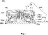
- Fig. 7 shows a cross-sectional view of the fastening device 100a of Fig. 6 .
- the fastening device 100a includes a case unit (not labeled), a spool 300a, a driving unit 400a, a knob 500a and a connecting unit 600a.
- the structure and relation of the case unit, the spool 300a, the driving unit 400a and the knob 500a are similar to that of the case unit 200, the spool 300, the driving unit 400 and the knob 500 in the first embodiment, but the structure of the connecting unit 600a is different from the connecting unit 600 of the first embodiment.
- the connecting unit 600a includes a first par set and a second part set 620a.
- the first part set includes a fastening barrel 610a.
- the second part set 620a includes a stop ring 621a and a screw bar 622a.
- the stop ring 621a is limited within the large-diameter segment (not labeled), and the screw bar 622a passes through the stop ring 621a and the small-diameter segment (not labeled) to screw with the fastening barrel 610a.
- the fastening barrel 610a can include a lower engaging portion 611a.
- the stop ring 621a includes an inner engaging groove 6211a, and the inner engaging groove 6211a is configured to engage with the lower engaging portion 611a.
- the knob 500a can include a boss (not labeled) protruding toward the inner space (not labeled) along the axial direction.
- the fastening barrel 610a can further include an upper engaging portion 612a connected to the lower engaging portion 611a, and the upper engaging portion 612a is engaged with the boss.
- the stop ring 621a further includes a bottom portion 6213a and a body portion 6212a.
- the body portion 6212a is connected to the bottom portion 6213a, and the inner engaging groove 6211a is located at the body portion 6212a.
- the shape of the upper engaging portion 612a of the fastening barrel 610a fits the through hole (not labeled) of the boss, and the shape of the lower engaging portion 611a fits the inner engaging groove 6211a.
- the fastening barrel 610a passes through the through hole, the upper engaging portion 612a is engaged with the boss, and the lower engaging portion 611a exposes from the boss to protrude toward the small-diameter segment.
- the body portion 6212a of the stop ring 621a passes through the small-diameter segment, and the inner engaging groove 6211a is engaged with the lower engaging portion 611a.
- the bottom portion 6213a is remained in the large-diameter segment to be limited within the large-diameter segment, and the screw bar 622a can fasten into the fastening barrel 610a upward from a bottom side thereof along the axial direction, thereby completing combination of the knob 500a, the driving unit 400a, the spool 300a and the annular wall 220a.
- the spool 300a may rub against the second part set 620a, and because the stop ring 621a of the second part set 620a is engaged with the boss through the fastening barrel 610a, rotation of the second part set 620a caused by the friction can be avoided, which also avoids separation between the first part set and the second part set 620a.
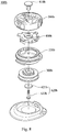
- Fig. 8 shows a three-dimensional exploded view of a fastening device 100b according to a third embodiment of the present disclosure.
- Fig. 9 shows a cross-sectional view of the fastening device 100b of Fig. 8 .
- the fastening device 100b includes a case unit (not shown), a spool 300b, a driving unit 400b, a knob 500b and a connecting unit 600b.
- the structure and relation of the case unit, the spool 300b, the driving unit 400b and the knob 500b are similar to that of the case unit, the spool 300a, the driving unit 400a and the knob 500a in the second embodiment, but the structure of the connecting unit 600b is different from the connecting unit 600a of the second embodiment.
- the first part set of the connecting unit 600b includes a fastening barrel 610b
- the second part set 620b includes a stop ring 621b and a screw bar 622b.
- the structure of the fastening barrel 610b is identical to the fastening barrel 610a of the second embodiment, but the lower engaging portion is omitted while the length of the upper engaging portion along the axial direction is elongated to protrude into the small-diameter segment.
- the present disclosure includes the above but is not limited thereto.
- the stop ring 621b has a ring structure
- the fastening barrel 610b includes a lower end surface 611b.
- the stop ring 621b is abutted against the lower end surface 611b, such that combination of the knob 500b, the driving unit 400b, the spool 300b and the annular wall 220b are completed.
- the spool 300b may rub against the second part set 620b, and because the stop ring 621b is forced by the screw bar 622b to abut against the lower end surface 611b, the friction between the stop ring 621b, the screw bar 622b and the lower end surface 611b is larger than that between the spool 300b and the stop ring 621b; therefore, rotation of the second part set 620b caused by the friction can be avoided, which also avoids separation between the first part set and the second part set 620b.
- Fig. 10 shows a three-dimensional exploded view of a fastening device 100c according to a fourth embodiment of the present disclosure.
- Fig. 11 shows a cross-sectional view of the fastening device 100c of Fig. 10 .
- the fastening device 100c includes a case unit (not shown), a spool 300c, a driving unit 400c, a knob 500c and a connecting unit 600c.
- the structure and relation of the case unit, the spool 300c, the driving unit 400c and the knob 500c are similar to that of the case unit, the spool 300b, the driving unit 400b and the knob 500b in the third embodiment, but the structure of the connecting unit 600c is different from the connecting unit 600b of the third embodiment.
- the first part set of the connecting unit 600c includes a fastening barrel 610c
- the second part set includes a screw bar 620c.
- the screw bar 620c includes a head portion 622c and a bar portion 621c, and the bar portion 621c is connected to the head portion 622c.
- the bar portion 621c inserts in the axial space to fasten the fastening barrel 610c, and the head portion 622c is limited within the large-diameter segment.
- the diameter of the head portion 622c can be larger than the diameter of the small-diameter segment, and the diameter of the screw bar 620c is smaller than the large-diameter segment, such that the screw bar 620c can be limited within the large-diameter segment, thereby completing combination of the knob 500c, the driving unit 400c, the spool 300c and the annular wall 220c.
- the spool 300c may rub against the second part set, and therefore the fastening force between the screw bar 620c and the fastening barrel 610c can be enlarged when fastening the screw bar 620c.
- the pitch width thereof can be widened, or a glue can be dispended thereon, which avoids rotation of the second part set caused by friction and separation between the first part set and the second part set.
- the connecting unit can have a boss structure, which can be integrally connected to the knob and can protrude into the axial space, or it can be secured on the knob by adhesion of glue.
- the connecting unit can include a lower flange, and with the upper end connected to the knob and the lower flanged limited within the large-diameter segment, the combination of the knob, the driving unit, the spool and the annular wall can be completed.
Applications Claiming Priority (2)
| Application Number | Priority Date | Filing Date | Title |
|---|---|---|---|
| CN201811275429.6A CN111115389B (zh) | 2018-10-30 | 2018-10-30 | 紧固装置 |
| PCT/CN2019/095132 WO2020087976A1 (zh) | 2018-10-30 | 2019-07-08 | 紧固装置 |
Publications (2)
| Publication Number | Publication Date |
|---|---|
| EP3875415A1 true EP3875415A1 (de) | 2021-09-08 |
| EP3875415A4 EP3875415A4 (de) | 2022-07-13 |
Family
ID=70462912
Family Applications (1)
| Application Number | Title | Priority Date | Filing Date |
|---|---|---|---|
| EP19878330.0A Pending EP3875415A4 (de) | 2018-10-30 | 2019-07-08 | Befestigungsvorrichtung |
Country Status (7)
| Country | Link |
|---|---|
| US (1) | US11805856B2 (de) |
| EP (1) | EP3875415A4 (de) |
| JP (1) | JP7111834B2 (de) |
| KR (1) | KR102576708B1 (de) |
| CN (1) | CN111115389B (de) |
| TW (4) | TWI745947B (de) |
| WO (1) | WO2020087976A1 (de) |
Families Citing this family (20)
| Publication number | Priority date | Publication date | Assignee | Title |
|---|---|---|---|---|
| US11751634B2 (en) | 2016-11-11 | 2023-09-12 | Chin-Chu Chen | Fastening device and lace assembling method |
| CN111115389B (zh) | 2018-10-30 | 2022-04-05 | 陈金柱 | 紧固装置 |
| US12207706B2 (en) | 2018-10-30 | 2025-01-28 | Chin-Chu Chen | Fastening device |
| US11730238B2 (en) | 2020-02-14 | 2023-08-22 | Shift Holding, LLC | Shift reel and related methods |
| CN113317592A (zh) * | 2020-02-28 | 2021-08-31 | 金镇镐 | 鞋带收紧装置 |
| KR102160426B1 (ko) * | 2020-07-14 | 2020-09-28 | 주식회사 스핀온 | 와이어 조임장치 |
| JP2022064759A (ja) * | 2020-10-14 | 2022-04-26 | 日本電産株式会社 | スプール及びそれを備えたレーシングモジュール |
| EP4275541A4 (de) * | 2021-01-08 | 2024-06-19 | Chin-Chu Chen | Befestigungsvorrichtung und bindelinienmontageverfahren |
| USD1007838S1 (en) * | 2021-01-25 | 2023-12-19 | Fidlock Gmbh | Winch |
| CN114906374A (zh) * | 2021-02-09 | 2022-08-16 | 陈臆霙 | 紧固装置及系线收放方法 |
| USD1014695S1 (en) * | 2021-03-24 | 2024-02-13 | Shift Holding, LLC | Shift reel |
| CN115137124B (zh) * | 2021-03-31 | 2024-04-12 | 陈金柱 | 紧固装置及紧固装置安装方法 |
| CN113148774A (zh) * | 2021-05-25 | 2021-07-23 | 泉州鑫图鞋材有限公司 | 半手动旋转收放绳扣 |
| KR20240017771A (ko) * | 2021-06-08 | 2024-02-08 | 친-추 첸 | 체결 디바이스 |
| WO2023011661A1 (zh) * | 2021-08-06 | 2023-02-09 | 刘荣兴 | 一种系带器 |
| CN116509108A (zh) * | 2022-01-21 | 2023-08-01 | 深圳市爱康伟达智能医疗科技有限公司 | 一种新型的系带装置及其止逆机构 |
| CN116369635A (zh) * | 2022-10-17 | 2023-07-04 | 东莞市壹创信息科技有限公司 | 离合收绳器 |
| US12599121B2 (en) * | 2023-03-17 | 2026-04-14 | Juka Innovations Corporation | Fishing line to lure connector |
| USD1107408S1 (en) * | 2023-05-17 | 2025-12-30 | Boa Technology, Inc. | Base member for a lace tightening device |
| WO2025042440A1 (en) * | 2023-08-23 | 2025-02-27 | Pride Manufacturing Company, Llc D/B/A Gathr Outdoors | Systems and methods for a rotary closure |
Family Cites Families (53)
| Publication number | Priority date | Publication date | Assignee | Title |
|---|---|---|---|---|
| US5157813A (en) * | 1991-10-31 | 1992-10-27 | William Carroll | Shoelace tensioning device |
| JPH07208A (ja) * | 1991-12-20 | 1995-01-06 | Kobatsuku:Kk | 靴紐締付具 |
| TW309189U (en) * | 1996-12-17 | 1997-06-21 | Zheng-Ting Lai | Withdraws box structure of hard disk |
| US7017846B2 (en) * | 2004-02-20 | 2006-03-28 | Comstar Communications Ltd. | Retractable cable winder |
| US7516914B2 (en) * | 2004-05-07 | 2009-04-14 | Enventys, Llc | Bi-directional device |
| US7367522B2 (en) * | 2005-10-14 | 2008-05-06 | Chin Chu Chen | String fastening device |
| CN201015448Y (zh) * | 2007-02-02 | 2008-02-06 | 盟汉塑胶股份有限公司 | 鞋卷线器 |
| BRPI0722115A2 (pt) | 2007-10-12 | 2015-10-13 | Latchways Plc | absorvedor de energia rotacional, dispositivo de segurança e sistema de apreensão de queda |
| KR101688997B1 (ko) * | 2008-11-21 | 2016-12-22 | 보아 테크놀러지, 인크. | 릴 기반 끈 조임 시스템 |
| TW201032749A (en) * | 2009-03-12 | 2010-09-16 | jin-zhu Chen | Fastener structure |
| US8245371B2 (en) * | 2009-04-01 | 2012-08-21 | Chin Chu Chen | String securing device |
| US20100270413A1 (en) * | 2009-04-27 | 2010-10-28 | Chin Wei Chien | Rotation-type single-pull retraction mechanism |
| EP2269479A1 (de) * | 2009-06-30 | 2011-01-05 | Campagnolo Sportswear S.r.l. | Schnüranhnliche Schliessvorrichtung für Fahrradschuh |
| KR100953398B1 (ko) * | 2009-12-31 | 2010-04-20 | 주식회사 신경 | 신발끈 조임장치 |
| TW201127310A (en) * | 2010-02-11 | 2011-08-16 | jin-zhu Chen | Step-less finetuning buckle |
| KR20200077624A (ko) * | 2010-04-30 | 2020-06-30 | 보아 테크놀러지, 인크. | 릴 기반 끈 조임 시스템 |
| US9375053B2 (en) * | 2012-03-15 | 2016-06-28 | Boa Technology, Inc. | Tightening mechanisms and applications including the same |
| CN201718602U (zh) * | 2010-05-11 | 2011-01-26 | 胡荣富 | 鞋卷线器 |
| US8353087B2 (en) * | 2011-03-07 | 2013-01-15 | Chin-Chu Chen | Closure device |
| KR101099458B1 (ko) * | 2011-07-25 | 2011-12-27 | 주식회사 신경 | 신발끈 조임장치 |
| US9101181B2 (en) * | 2011-10-13 | 2015-08-11 | Boa Technology Inc. | Reel-based lacing system |
| US20150191326A1 (en) | 2012-06-22 | 2015-07-09 | Revision Military S.A.R.L. | Tensioning reel |
| US10251451B2 (en) * | 2013-03-05 | 2019-04-09 | Boa Technology Inc. | Closure devices including incremental release mechanisms and methods therefor |
| EP4721617A2 (de) * | 2013-06-05 | 2026-04-08 | Boa Technology, Inc. | Komponenten und verfahren für eine integrierte verschlussvorrichtung |
| DE112014003135B4 (de) * | 2013-07-02 | 2020-12-24 | Boa Technology Inc. | Rolle zur verwendung mit einem verschnürungssystem zum festziehen eines gegenstandes sowie vorrichtungen hierzu und verfahren zum zusammenbauen einer vorrichtung zum festziehen eines gegenstandes |
| CN203492894U (zh) | 2013-09-11 | 2014-03-26 | 陈金柱 | 带体收放装置 |
| TWI513423B (zh) | 2013-11-11 | 2015-12-21 | Chin Chu Chen | 帶體收放裝置及其收放方法 |
| TWI561453B (en) * | 2014-02-17 | 2016-12-11 | Chin Chu Chen | A device for tightening and loosening a lace |
| US9364054B2 (en) * | 2014-04-09 | 2016-06-14 | Tristan S. Gittens | Accessory cinching device |
| KR101438572B1 (ko) | 2014-04-24 | 2014-09-12 | 주식회사 신경 | 와이어 조임장치 |
| US20160058130A1 (en) * | 2014-08-28 | 2016-03-03 | Boa Technology Inc. | Multi-purpose closure system |
| JP6605023B2 (ja) * | 2014-09-05 | 2019-11-13 | 金柱 陳 | ひもの締緩装置及びその締緩方法 |
| TWM507670U (zh) | 2015-03-19 | 2015-09-01 | Nifco Taiwan Corp | 繩索調整扣具 |
| KR20160131296A (ko) * | 2015-05-06 | 2016-11-16 | 주식회사 신경 | 커버 교체가 가능한 와이어 조임장치 |
| TWM514461U (zh) | 2015-08-18 | 2015-12-21 | 陳金柱 | 收放線結構 |
| CN204895922U (zh) | 2015-08-24 | 2015-12-23 | 陈金柱 | 收放线结构 |
| CN204969764U (zh) * | 2015-09-24 | 2016-01-20 | 蒋小平 | 一种可自动松紧鞋带的装置 |
| CN106919220B (zh) * | 2015-12-25 | 2018-06-05 | 陈金柱 | 紧固装置 |
| KR101765680B1 (ko) | 2016-01-18 | 2017-08-08 | 주식회사 비에스이 | 이어폰용 와이어 자동 감김 장치 |
| DE112016001803T5 (de) * | 2016-02-11 | 2018-02-22 | Young Ho Ha | Drahtspannvorrichtung |
| JP6810530B2 (ja) * | 2016-04-04 | 2021-01-06 | 株式会社アルペン | 巻取装置 |
| TWM529400U (zh) * | 2016-05-11 | 2016-10-01 | zhi-feng Xu | 線材收放定位裝置及具有其之鞋子 |
| US10918165B2 (en) | 2016-11-11 | 2021-02-16 | Chin-Chu Chen | Fastening device and lace assembling method thereof |
| CN206187398U (zh) | 2016-11-11 | 2017-05-24 | 陈金柱 | 紧固装置 |
| CN206499022U (zh) * | 2017-02-15 | 2017-09-19 | 翁中飞 | 钢丝鞋带旋转扣 |
| CN206565397U (zh) * | 2017-03-14 | 2017-10-20 | 福建省晋江市池店镇金兴鞋业有限公司 | 一种新型的鞋带旋转扣 |
| KR101862571B1 (ko) | 2017-05-19 | 2018-05-30 | 크레신 주식회사 | 와이어 감김 장치 |
| CN207061543U (zh) | 2017-06-19 | 2018-03-02 | 天津送变电工程公司 | 一种多功能电气试验导线自动收线器 |
| CN111115389B (zh) | 2018-10-30 | 2022-04-05 | 陈金柱 | 紧固装置 |
| CN111115388B (zh) | 2018-10-30 | 2021-11-19 | 陈金柱 | 紧固装置 |
| TWI694216B (zh) * | 2019-04-25 | 2020-05-21 | 陳金柱 | 緊固裝置 |
| CN111846339B (zh) | 2019-04-30 | 2022-04-15 | 陈金柱 | 紧固装置 |
| JP7454267B2 (ja) | 2019-05-01 | 2024-03-22 | ボア テクノロジー,インコーポレイテッド | リール式クロージャーシステム |
-
2018
- 2018-10-30 CN CN201811275429.6A patent/CN111115389B/zh active Active
-
2019
- 2019-07-01 TW TW109114610A patent/TWI745947B/zh active
- 2019-07-01 TW TW111126519A patent/TWI822184B/zh active
- 2019-07-01 TW TW110137611A patent/TWI775639B/zh active
- 2019-07-01 TW TW108123146A patent/TWI745708B/zh active
- 2019-07-08 JP JP2020560490A patent/JP7111834B2/ja active Active
- 2019-07-08 KR KR1020217009007A patent/KR102576708B1/ko active Active
- 2019-07-08 WO PCT/CN2019/095132 patent/WO2020087976A1/zh not_active Ceased
- 2019-07-08 EP EP19878330.0A patent/EP3875415A4/de active Pending
- 2019-07-08 US US17/271,602 patent/US11805856B2/en active Active
Also Published As
| Publication number | Publication date |
|---|---|
| TWI822184B (zh) | 2023-11-11 |
| CN111115389B (zh) | 2022-04-05 |
| TW202206365A (zh) | 2022-02-16 |
| JP2021531219A (ja) | 2021-11-18 |
| TW202033439A (zh) | 2020-09-16 |
| US11805856B2 (en) | 2023-11-07 |
| KR102576708B1 (ko) | 2023-09-07 |
| JP7111834B2 (ja) | 2022-08-02 |
| WO2020087976A1 (zh) | 2020-05-07 |
| KR20210049884A (ko) | 2021-05-06 |
| CN111115389A (zh) | 2020-05-08 |
| TWI745947B (zh) | 2021-11-11 |
| US20210186160A1 (en) | 2021-06-24 |
| TW202243986A (zh) | 2022-11-16 |
| EP3875415A4 (de) | 2022-07-13 |
| TWI745708B (zh) | 2021-11-11 |
| TWI775639B (zh) | 2022-08-21 |
| TW202016003A (zh) | 2020-05-01 |
Similar Documents
| Publication | Publication Date | Title |
|---|---|---|
| EP3875415A1 (de) | Befestigungsvorrichtung | |
| US12207706B2 (en) | Fastening device | |
| US12419390B2 (en) | Fastening device | |
| US11607014B2 (en) | Fastening device and lace assembling method | |
| KR102576704B1 (ko) | 체결 디바이스 | |
| JP7394431B2 (ja) | 一体化されたクロージャー装置部品および方法 | |
| US12156570B2 (en) | Fastening device | |
| EP3011856B1 (de) | Aufwickelvorrichtung für schnürriemen | |
| EP3539405B1 (de) | Befestigungsvorrichtung und verfahren zum zusammensetzen derselben | |
| JP6105404B2 (ja) | 靴紐巻取用リール | |
| EP4544950A2 (de) | Befestigungsvorrichtung | |
| EP4321050A1 (de) | Befestigungsvorrichtung | |
| WO2018030108A1 (ja) | 巻取装置 | |
| TWI719354B (zh) | 緊固裝置 | |
| EP4292971A1 (de) | Befestigungsvorrichtung und kabelbinderspann- und -löseverfahren | |
| EP4480339B1 (de) | Befestigungsvorrichtung | |
| EP4275540A1 (de) | Befestigungsvorrichtung und schnürsenkelmontageverfahren | |
| TWI747681B (zh) | 緊固裝置 | |
| TW202016004A (zh) | 緊固裝置 |
Legal Events
| Date | Code | Title | Description |
|---|---|---|---|
| STAA | Information on the status of an ep patent application or granted ep patent |
Free format text: STATUS: THE INTERNATIONAL PUBLICATION HAS BEEN MADE |
|
| PUAI | Public reference made under article 153(3) epc to a published international application that has entered the european phase |
Free format text: ORIGINAL CODE: 0009012 |
|
| STAA | Information on the status of an ep patent application or granted ep patent |
Free format text: STATUS: REQUEST FOR EXAMINATION WAS MADE |
|
| 17P | Request for examination filed |
Effective date: 20210423 |
|
| AK | Designated contracting states |
Kind code of ref document: A1 Designated state(s): AL AT BE BG CH CY CZ DE DK EE ES FI FR GB GR HR HU IE IS IT LI LT LU LV MC MK MT NL NO PL PT RO RS SE SI SK SM TR |
|
| DAV | Request for validation of the european patent (deleted) | ||
| DAX | Request for extension of the european patent (deleted) | ||
| REG | Reference to a national code |
Ref country code: DE Ref legal event code: R079 Free format text: PREVIOUS MAIN CLASS: B65H0075480000 Ipc: A43C0011160000 |
|
| A4 | Supplementary search report drawn up and despatched |
Effective date: 20220610 |
|
| RIC1 | Information provided on ipc code assigned before grant |
Ipc: A43C 11/16 20060101AFI20220603BHEP |
|
| STAA | Information on the status of an ep patent application or granted ep patent |
Free format text: STATUS: EXAMINATION IS IN PROGRESS |
|
| 17Q | First examination report despatched |
Effective date: 20240216 |
|
| GRAP | Despatch of communication of intention to grant a patent |
Free format text: ORIGINAL CODE: EPIDOSNIGR1 |
|
| STAA | Information on the status of an ep patent application or granted ep patent |
Free format text: STATUS: GRANT OF PATENT IS INTENDED |
|
| INTG | Intention to grant announced |
Effective date: 20260216 |