EP3875630A1 - Film de revêtement pulvérisé pour élément de coulissement et dispositif de coulissement équipé de celui-ci - Google Patents
Film de revêtement pulvérisé pour élément de coulissement et dispositif de coulissement équipé de celui-ci Download PDFInfo
- Publication number
- EP3875630A1 EP3875630A1 EP18938570.1A EP18938570A EP3875630A1 EP 3875630 A1 EP3875630 A1 EP 3875630A1 EP 18938570 A EP18938570 A EP 18938570A EP 3875630 A1 EP3875630 A1 EP 3875630A1
- Authority
- EP
- European Patent Office
- Prior art keywords
- sprayed coating
- thermal sprayed
- sliding member
- sliding
- coating
- Prior art date
- Legal status (The legal status is an assumption and is not a legal conclusion. Google has not performed a legal analysis and makes no representation as to the accuracy of the status listed.)
- Granted
Links
Images



Classifications
-
- C—CHEMISTRY; METALLURGY
- C23—COATING METALLIC MATERIAL; COATING MATERIAL WITH METALLIC MATERIAL; CHEMICAL SURFACE TREATMENT; DIFFUSION TREATMENT OF METALLIC MATERIAL; COATING BY VACUUM EVAPORATION, BY SPUTTERING, BY ION IMPLANTATION OR BY CHEMICAL VAPOUR DEPOSITION, IN GENERAL; INHIBITING CORROSION OF METALLIC MATERIAL OR INCRUSTATION IN GENERAL
- C23C—COATING METALLIC MATERIAL; COATING MATERIAL WITH METALLIC MATERIAL; SURFACE TREATMENT OF METALLIC MATERIAL BY DIFFUSION INTO THE SURFACE, BY CHEMICAL CONVERSION OR SUBSTITUTION; COATING BY VACUUM EVAPORATION, BY SPUTTERING, BY ION IMPLANTATION OR BY CHEMICAL VAPOUR DEPOSITION, IN GENERAL
- C23C4/00—Coating by spraying the coating material in the molten state, e.g. by flame, plasma or electric discharge
- C23C4/04—Coating by spraying the coating material in the molten state, e.g. by flame, plasma or electric discharge characterised by the coating material
- C23C4/06—Metallic material
-
- F—MECHANICAL ENGINEERING; LIGHTING; HEATING; WEAPONS; BLASTING
- F02—COMBUSTION ENGINES; HOT-GAS OR COMBUSTION-PRODUCT ENGINE PLANTS
- F02F—CYLINDERS, PISTONS OR CASINGS, FOR COMBUSTION ENGINES; ARRANGEMENTS OF SEALINGS IN COMBUSTION ENGINES
- F02F3/00—Pistons
- F02F3/10—Pistons having surface coverings
-
- C—CHEMISTRY; METALLURGY
- C23—COATING METALLIC MATERIAL; COATING MATERIAL WITH METALLIC MATERIAL; CHEMICAL SURFACE TREATMENT; DIFFUSION TREATMENT OF METALLIC MATERIAL; COATING BY VACUUM EVAPORATION, BY SPUTTERING, BY ION IMPLANTATION OR BY CHEMICAL VAPOUR DEPOSITION, IN GENERAL; INHIBITING CORROSION OF METALLIC MATERIAL OR INCRUSTATION IN GENERAL
- C23C—COATING METALLIC MATERIAL; COATING MATERIAL WITH METALLIC MATERIAL; SURFACE TREATMENT OF METALLIC MATERIAL BY DIFFUSION INTO THE SURFACE, BY CHEMICAL CONVERSION OR SUBSTITUTION; COATING BY VACUUM EVAPORATION, BY SPUTTERING, BY ION IMPLANTATION OR BY CHEMICAL VAPOUR DEPOSITION, IN GENERAL
- C23C4/00—Coating by spraying the coating material in the molten state, e.g. by flame, plasma or electric discharge
- C23C4/02—Pretreatment of the material to be coated, e.g. for coating on selected surface areas
-
- C—CHEMISTRY; METALLURGY
- C23—COATING METALLIC MATERIAL; COATING MATERIAL WITH METALLIC MATERIAL; CHEMICAL SURFACE TREATMENT; DIFFUSION TREATMENT OF METALLIC MATERIAL; COATING BY VACUUM EVAPORATION, BY SPUTTERING, BY ION IMPLANTATION OR BY CHEMICAL VAPOUR DEPOSITION, IN GENERAL; INHIBITING CORROSION OF METALLIC MATERIAL OR INCRUSTATION IN GENERAL
- C23C—COATING METALLIC MATERIAL; COATING MATERIAL WITH METALLIC MATERIAL; SURFACE TREATMENT OF METALLIC MATERIAL BY DIFFUSION INTO THE SURFACE, BY CHEMICAL CONVERSION OR SUBSTITUTION; COATING BY VACUUM EVAPORATION, BY SPUTTERING, BY ION IMPLANTATION OR BY CHEMICAL VAPOUR DEPOSITION, IN GENERAL
- C23C4/00—Coating by spraying the coating material in the molten state, e.g. by flame, plasma or electric discharge
- C23C4/04—Coating by spraying the coating material in the molten state, e.g. by flame, plasma or electric discharge characterised by the coating material
- C23C4/06—Metallic material
- C23C4/08—Metallic material containing only metal elements
-
- C—CHEMISTRY; METALLURGY
- C23—COATING METALLIC MATERIAL; COATING MATERIAL WITH METALLIC MATERIAL; CHEMICAL SURFACE TREATMENT; DIFFUSION TREATMENT OF METALLIC MATERIAL; COATING BY VACUUM EVAPORATION, BY SPUTTERING, BY ION IMPLANTATION OR BY CHEMICAL VAPOUR DEPOSITION, IN GENERAL; INHIBITING CORROSION OF METALLIC MATERIAL OR INCRUSTATION IN GENERAL
- C23C—COATING METALLIC MATERIAL; COATING MATERIAL WITH METALLIC MATERIAL; SURFACE TREATMENT OF METALLIC MATERIAL BY DIFFUSION INTO THE SURFACE, BY CHEMICAL CONVERSION OR SUBSTITUTION; COATING BY VACUUM EVAPORATION, BY SPUTTERING, BY ION IMPLANTATION OR BY CHEMICAL VAPOUR DEPOSITION, IN GENERAL
- C23C4/00—Coating by spraying the coating material in the molten state, e.g. by flame, plasma or electric discharge
- C23C4/12—Coating by spraying the coating material in the molten state, e.g. by flame, plasma or electric discharge characterised by the method of spraying
-
- C—CHEMISTRY; METALLURGY
- C23—COATING METALLIC MATERIAL; COATING MATERIAL WITH METALLIC MATERIAL; CHEMICAL SURFACE TREATMENT; DIFFUSION TREATMENT OF METALLIC MATERIAL; COATING BY VACUUM EVAPORATION, BY SPUTTERING, BY ION IMPLANTATION OR BY CHEMICAL VAPOUR DEPOSITION, IN GENERAL; INHIBITING CORROSION OF METALLIC MATERIAL OR INCRUSTATION IN GENERAL
- C23C—COATING METALLIC MATERIAL; COATING MATERIAL WITH METALLIC MATERIAL; SURFACE TREATMENT OF METALLIC MATERIAL BY DIFFUSION INTO THE SURFACE, BY CHEMICAL CONVERSION OR SUBSTITUTION; COATING BY VACUUM EVAPORATION, BY SPUTTERING, BY ION IMPLANTATION OR BY CHEMICAL VAPOUR DEPOSITION, IN GENERAL
- C23C4/00—Coating by spraying the coating material in the molten state, e.g. by flame, plasma or electric discharge
- C23C4/12—Coating by spraying the coating material in the molten state, e.g. by flame, plasma or electric discharge characterised by the method of spraying
- C23C4/131—Wire arc spraying
-
- C—CHEMISTRY; METALLURGY
- C23—COATING METALLIC MATERIAL; COATING MATERIAL WITH METALLIC MATERIAL; CHEMICAL SURFACE TREATMENT; DIFFUSION TREATMENT OF METALLIC MATERIAL; COATING BY VACUUM EVAPORATION, BY SPUTTERING, BY ION IMPLANTATION OR BY CHEMICAL VAPOUR DEPOSITION, IN GENERAL; INHIBITING CORROSION OF METALLIC MATERIAL OR INCRUSTATION IN GENERAL
- C23C—COATING METALLIC MATERIAL; COATING MATERIAL WITH METALLIC MATERIAL; SURFACE TREATMENT OF METALLIC MATERIAL BY DIFFUSION INTO THE SURFACE, BY CHEMICAL CONVERSION OR SUBSTITUTION; COATING BY VACUUM EVAPORATION, BY SPUTTERING, BY ION IMPLANTATION OR BY CHEMICAL VAPOUR DEPOSITION, IN GENERAL
- C23C4/00—Coating by spraying the coating material in the molten state, e.g. by flame, plasma or electric discharge
- C23C4/12—Coating by spraying the coating material in the molten state, e.g. by flame, plasma or electric discharge characterised by the method of spraying
- C23C4/14—Coating by spraying the coating material in the molten state, e.g. by flame, plasma or electric discharge characterised by the method of spraying for coating elongate material
- C23C4/16—Wires; Tubes
-
- F—MECHANICAL ENGINEERING; LIGHTING; HEATING; WEAPONS; BLASTING
- F02—COMBUSTION ENGINES; HOT-GAS OR COMBUSTION-PRODUCT ENGINE PLANTS
- F02F—CYLINDERS, PISTONS OR CASINGS, FOR COMBUSTION ENGINES; ARRANGEMENTS OF SEALINGS IN COMBUSTION ENGINES
- F02F3/00—Pistons
- F02F3/0084—Pistons the pistons being constructed from specific materials
-
- F—MECHANICAL ENGINEERING; LIGHTING; HEATING; WEAPONS; BLASTING
- F04—POSITIVE - DISPLACEMENT MACHINES FOR LIQUIDS; PUMPS FOR LIQUIDS OR ELASTIC FLUIDS
- F04B—POSITIVE-DISPLACEMENT MACHINES FOR LIQUIDS; PUMPS
- F04B53/00—Component parts, details or accessories not provided for in, or of interest apart from, groups F04B1/00 - F04B23/00 or F04B39/00 - F04B47/00
- F04B53/14—Pistons, piston-rods or piston-rod connections
-
- F—MECHANICAL ENGINEERING; LIGHTING; HEATING; WEAPONS; BLASTING
- F04—POSITIVE - DISPLACEMENT MACHINES FOR LIQUIDS; PUMPS FOR LIQUIDS OR ELASTIC FLUIDS
- F04B—POSITIVE-DISPLACEMENT MACHINES FOR LIQUIDS; PUMPS
- F04B53/00—Component parts, details or accessories not provided for in, or of interest apart from, groups F04B1/00 - F04B23/00 or F04B39/00 - F04B47/00
- F04B53/16—Casings; Cylinders; Cylinder liners or heads; Fluid connections
- F04B53/162—Adaptations of cylinders
-
- F—MECHANICAL ENGINEERING; LIGHTING; HEATING; WEAPONS; BLASTING
- F16—ENGINEERING ELEMENTS AND UNITS; GENERAL MEASURES FOR PRODUCING AND MAINTAINING EFFECTIVE FUNCTIONING OF MACHINES OR INSTALLATIONS; THERMAL INSULATION IN GENERAL
- F16J—PISTONS; CYLINDERS; SEALINGS
- F16J1/00—Pistons; Trunk pistons; Plungers
- F16J1/01—Pistons; Trunk pistons; Plungers characterised by the use of particular materials
-
- F—MECHANICAL ENGINEERING; LIGHTING; HEATING; WEAPONS; BLASTING
- F02—COMBUSTION ENGINES; HOT-GAS OR COMBUSTION-PRODUCT ENGINE PLANTS
- F02F—CYLINDERS, PISTONS OR CASINGS, FOR COMBUSTION ENGINES; ARRANGEMENTS OF SEALINGS IN COMBUSTION ENGINES
- F02F1/00—Cylinders; Cylinder heads
Definitions
- the present invention relates to a thermal sprayed coating for a sliding member, and more specifically relates to a thermal sprayed coating for a sliding member, which contains an iron-based alloy containing chromium and has improved corrosion resistance.
- Aluminum or aluminum alloy cylinder blocks for an internal combustion engine are provided with a cast iron liner on an inner circumferential surface of the cylinder bore, whereby functions, such as strength, wear resistance, and sliding characteristics, are improved.
- the cast iron liner requires a thickness of a certain degree due to the production method of the cylinder block using the cast iron liner, and thus the weight of the entire cylinder block is increased.
- a gap is often generated on a surface joined to the cylinder block and thermal conductivity is often decreased.
- a thermal sprayed coating is formed on an inner circumferential surface of a cylinder bore, whereby weight of a cylinder block is reduced.
- Patent Document 1 discloses a thermal spray wire to be used in thermal spraying on an inner surface of a cylinder bore.
- a stainless steel-based thermal sprayed coating that contains chromium (Cr) is prevented from being corroded by low-quality fuel that contains a large amount of sulfur, but the thermal sprayed coating is reduced in peeling resistance due to lowering of bonding strength between thermal sprayed droplets that form the thermal sprayed coating.
- the decrease in bonding strength between thermal sprayed droplets can be prevented by adding a predetermined amount of manganese (Mn).
- Patent Document 1 JP 2012-41617A
- the thermal sprayed coating disclosed in Patent Document 1 does not have sufficient strength, and the thermal sprayed coating easily partially comes off from the surface to generate abrasive particles.
- the generated abrasive particles act as polishing agent and further wear the thermal sprayed coating.
- the present invention has been made in view of these problems in the prior art, and an object thereof is to provide an iron-based thermal sprayed coating for a sliding member, which has corrosion resistance and improved wear resistance.
- the inventors of the present invention have made an intensive research to achieve the above object and have found the following findings. That is, performing fining crystal grains in a thermal sprayed coating in addition to increasing hardness of the thermal sprayed coating, enables achieving the above object. Thus, the present invention has been completed.
- a thermal sprayed coating for a sliding member of the present invention is composed of an iron-based alloy containing chromium (Cr).
- the content of chromium is 8 mass % or more
- the thermal sprayed coating includes a structure in which crystal grains have an average grain diameter of 3 ⁇ m or less and the thermal sprayed coating has Vickers hardness of 300 Hv or more.
- a sliding device of the present invention includes a sliding member and a mating member, and the sliding member and the mating member each have a coating on a base material and mutually slide.
- the coating of the mating member is a hard carbon film
- the coating of the sliding member is the thermal sprayed coating for a sliding member.
- the thermal sprayed coating includes the structure in which crystal grains have an average grain diameter of 3 ⁇ m or less, and the thermal sprayed coating has Vickers hardness of 300 Hv or more.
- the present invention provides an iron-based thermal sprayed coating for a sliding member, which has improved wear resistance.
- the thermal sprayed coating for a sliding member (hereinafter simply referred to as a "thermal sprayed coating") is composed of a corrosion resistant iron-based alloy containing iron (Fe) as a main component and containing 8 mass % or more of chromium (Cr).
- the thermal sprayed coating includes a structure in which crystal grains have an average grain diameter of 3 ⁇ m or less, and the thermal sprayed coating has Vickers hardness of 300 Hv or more.
- the word "main component” in the present invention means a component that is contained in an amount of 50 mass % or more.
- the thermal sprayed coating has Vickers hardness of 300 Hv or more and further includes a structure in which crystal grains are fined, thereby hardly causing plastic deformation due to sliding and being superior in wear resistance.
- each of the crystal grains in the thermal sprayed coating structure have respective different crystal orientations, and a relationship between a tensile direction in sliding and the crystal orientation differs in respective crystal grains.
- a gap is generated or overlapping occurs in the vicinity of a crystal grain boundary, whereby the slip does not extend beyond the crystal grain boundary and stops at the crystal grain boundary.
- fined crystal grains in the thermal sprayed coating structure suppresses amount of dislocation slip and hardly causes plastic deformation when dislocation slip for plastic deformation occurs by sliding.
- the fined crystal grains increase strength and improve wear resistance by suppressing generation of abrasive particles.
- the grain diameter of the crystal grain can be adjusted by controlling a cooling rate of thermal sprayed droplets and the composition of the iron-based alloy.
- crystal grains are fined by performing thermal spraying on a base material having a high thermal conductivity, such as of aluminum or aluminum alloy, so as to rapidly cool thermal sprayed droplets.
- a base material having a high thermal conductivity such as of aluminum or aluminum alloy
- an iron-based alloy having a composition by which martensite is easily generated enables crystal grains to be fine.
- a half-value width of a grain size distribution of crystal grains is preferably 2.5 ⁇ m or less, and more preferably 1.2 ⁇ m or less.
- Crystal grains that have a sharp grain size distribution and that include a small amount of coarse crystal grains, suppress local occurrence of large plastic deformation in the thermal sprayed coating. Thus, the entire thermal sprayed coating is increased in strength, and wear resistance is improved.
- the grain size distribution of crystal grains can be adjusted by controlling the composition of the iron-based alloy.
- An iron-based alloy that contains carbon and manganese can yield fine martensite while preventing a coarse austenitic structure from remaining, whereby a sharp grain size distribution of crystal grains is obtained.
- the upper limit of hardness of the thermal sprayed coating is not specifically limited. However, if the thermal sprayed coating is too hard, when the thermal sprayed coating partially comes off from the surface to generate abrasive particles, the generated abrasive particles act as hard polishing agent and can reduce wear resistance.
- the upper limit of hardness depends on, e.g., tendency to generate abrasive particles. However, it is preferably 600 Hv or less, more preferably 450 Hv or less, and further preferably 400 Hv or less.
- the thermal sprayed coating preferably has an oxide ratio in cross section of 1 % or less.
- a thermal sprayed coating is formed by melting a thermal spray wire at high temperatures, and therefore, the thermal sprayed coating that is formed by oxidizing thermal sprayed droplets tends to contain oxides in a large amount.
- the thermal sprayed coating of the present invention contains the oxide at a ratio of 1 area % or less, thereby having superior wear resistance.
- the oxide has thermal conductivity smaller than those of metals, and the oxide has a high melting point and easily solidifies.
- oxide that are formed on a surface of a thermal sprayed droplet inhibits heat transmission from the thermal sprayed droplet to the base material, deformation of the thermal sprayed droplet, and metallic bonding between the thermal sprayed droplets, at the time of landing of the thermal sprayed droplet on the base material.
- the small ratio of an oxide in the thermal sprayed coating means that, when a thermal sprayed droplet lands on the base material, a thermal sprayed droplet loses heat by the base material and is rapidly cooled to form a structure having fined crystal grains. Moreover, the thermal sprayed droplet is sufficiently deformed and densely deposits, whereby a bonded area of the thermal sprayed droplets is increased. Meanwhile, all the thermal sprayed droplets in the thermal sprayed coating are strongly bonded to each other by a metallic bond, without the metallic bond's being broken by the oxide, whereby coating strength is improved, and partial coming-off from the surface is prevented.
- the ratio of the oxide in the thermal sprayed coating can be adjusted by a spraying atmosphere.
- the oxide in the thermal sprayed coating does not originate from the composition of the thermal spray wire, but are generated mainly by oxidation of high-temperature thermal sprayed droplets, as described above.
- thermal spraying is performed with the use of the non-oxidizing gas as a carrier gas. This suppresses generation of an oxide.
- the ratio of the oxide in the thermal sprayed coating is measured from an optical microscopic image of a cross section of the thermal sprayed coating, as follows: identifying oxide based on difference in brilliance, binarizing the cross-sectional image for quantification, and measuring the area % of the cross-section.
- the iron-based alloy contains 8 mass % or more of chromium and, as necessary, can contain other elements such as carbon (C), silicon (Si), manganese (Mn), nickel (Ni), and molybdenum (Mo).
- the iron-based alloy Due to chromium (Cr) contained in the iron-based alloy, a passive film that is able to repair itself is formed, and improves corrosion resistance against acids originating from NOx or a sulfur component of fuel.
- the iron-based alloy preferably contains 10 mass % or more of chromium.
- the upper limit of the content of chromium is not specifically limited. However, as the content of chromium increases, an austenitic structure increases while a martensitic structure is hardly formed, and grain diameters of crystal grains tend to be large. In view of this, the content of chromium is preferably 20 mass % or less, and more preferably 18 mass % or less.
- the content of carbon is preferably 0.005 mass % or more and 0.2 mass % or less, and more preferably, 0.01 mass % or more and 0.1 mass % or less. If the content of carbon is less than 0.005 mass %, hardness of the thermal sprayed coating tends to be reduced, and it may be difficult to obtain sufficient friction resistance. However, if the content of carbon exceeds 0.2 mass %, hardness of the thermal sprayed coating is increased, and wear characteristics against a mating member can be increased. In addition, in a case in which a coating of a mating member is a hard carbon film, which is described later, an affinity of the mating member with the coating is increased, and adhesion can occur to reduce friction resistance.
- the content of silicon (Si) is preferably 0.1 mass % or more and 0.5 mass % or less. If the content of silicon is less than 0.1 mass %, tensile strength of the thermal sprayed coating is lowered. On the other hand, if the content of silicon exceeds 0.5 mass %, wear resistance can be reduced.
- Silicon is hardly solid-solved in an iron-based alloy and is unevenly distributed on a surface of a thermal sprayed droplet. Due to this, microscopic fracture occurs at a grain boundary, starting from a single body silicon, silicon nitride, silicon oxide and the like, which are brittle and have low strength compared with an iron-based thermal sprayed coating, whereby a crack and coming-off easily occur from an interface of the thermal sprayed droplet.
- the content of manganese (Mn) is preferably 0.3 mass % or more and 4 mass % or less. Manganese is uniformly solid-solved in the entire thermal sprayed coating and facilitates formation of a martensitic structure in the thermal sprayed coating structure to fine crystal grains. Thus, a coarse austenitic structure hardly remains, and a grain size distribution of the crystal grains becomes sharp.
- the film thickness of the thermal sprayed coating is preferably 100 ⁇ m or more and 400 ⁇ m or less.
- the film thickness of the thermal sprayed coating is less than 100 ⁇ m, it is difficult to form recesses and projections having heights sufficient to enhance peeling resistance, and if the film thickness exceeds 400 ⁇ m, heat accumulates when thermal spraying is performed, whereby coating strength is lowered, and wear resistance may be reduced.
- the iron-based alloy for composing the thermal sprayed coating has a thermal conductivity lower than that of an aluminum or aluminum alloy base material, which will be described later, and thus, a cooling efficiency decreases as the film thickness of the thermal sprayed coating increases.
- the film thickness of the thermal sprayed coating represents a thickness from a bottom of the recesses and projections.
- the sliding device of the present invention includes a sliding member and a mating member that mutually slide.
- the mating member has a hard carbon film on a base material, and the sliding member includes the thermal sprayed coating for a sliding member, on a base material.
- the mating member which slides with the sliding member having the thermal sprayed coating, has the hard carbon film as a sliding surface, whereby seizure resistance is improved.
- seizure resistance is improved.
- a combination of the same types of materials reduces seizure resistance. The reason for this is that the combination of the same types of materials tends to occur adhesion due to their high mutual affinity and easily generates abrasive particles.
- the sliding mating material has the hard carbon film (DLC), and therefore, the thermal sprayed coating for a sliding member hardly occurs adhesion and exhibits greatly improved wear resistance, compared with a case in which a sliding mating material is other coating that is generally used for a piston ring, such as a chromium (Cr) coating or a chromium nitride (CrN) coating.
- DLC hard carbon film
- the surface roughness (Ra) of the hard carbon film is preferably 0.1 ⁇ m or less.
- the hard carbon film has high hardness, and therefore, if the surface roughness (Ra) exceeds 0.1 ⁇ m, wear characteristics against a mating member increase, whereby wear resistance can be easily reduced.
- the sliding device of the present invention can be suitably used for a piston and a cylinder block that are used in an internal combustion engine.
- a piston has the hard carbon film on a sliding surface, e.g. a piston ring, with a mating member, and a sliding member, such as a cylinder block, has the thermal sprayed coating on an inner surface of a bore that slides with the piston. With this configuration, superior friction resistance is obtained.
- Aluminum or aluminum alloy can be suitably used for the base material of each of the cylinder block and the piston, and these materials reduce weight of an internal combustion engine.
- An inner circumferential surface of a cylinder bore of an ADC12 alloy gasoline-engine cylinder block was grooved to have recesses and projections with heights of approximately 85 ⁇ m.
- a thermal sprayed coating having a film thickness of 270 ⁇ m from the bottom of the recesses and projections was formed by arc spraying method with the use of a thermal spray wire having a composition shown in Table 1.
- Thermal spraying was performed as follows. After the cylinder block was preheated to 120 °C, a nozzle was inserted into the cylinder bore at room temperature. Then, spraying of thermally spraying droplets was performed at 1200 L/min in the air atmosphere by using nitrogen gas for splashing thermally spraying droplets, while nitrogen gas was flowed at 500 L/min as a shielding gas.
- the formed thermal sprayed coating was ground in such a manner that a flat part, excluding a pit specific to the thermal sprayed coating, was finished to have a surface roughness (Ra) of 0.05 ⁇ m or less.
- the coating was evaluated by the following methods. The results of evaluation are shown in Table 1 together with the composition of the thermal sprayed coating.
- the composition of the thermal sprayed coating was quantitatively measured by dissolving a piece of the thermal sprayed coating obtained by scraping the cylinder block in nitric acid, followed by conducting an inductively coupled plasma analysis (IPC analysis).
- IPC analysis inductively coupled plasma analysis
- the thermal spray wire was also subjected to IPC analysis in a similar manner, and it was confirmed that the thermal sprayed coating and the thermal spray wire had the same composition.
- the amounts of oxygen and nitrogen were detection limits or less.
- Vickers hardness was measured on a selected part where pores in the thermal sprayed coating did not affect, at a load of 50 g, in accordance with "Vickers hardness test (JIS Z 2244)".
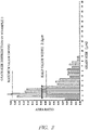
- a cross section of the thermal sprayed coating was subjected to plane analysis using electron probe microanalyzer (EPMA). Then, a grain diameter was calculated based on an area of a crystal grain by taking a discontinuous surface having deviation of crystal orientation of 5 degrees or more as a grain boundary. A grain size distribution (histogram) based on an area ratio was then generated, and an average grain diameter and a half-value width of crystal grains were obtained. Grain size distributions of Examples 1 and 3 and Comparative Examples 1 and 2 are shown in FIGs. 1 to 4 , respectively.
- a cross section of the thermal sprayed coating was subjected to plane analysis using electron probe microanalyzer (EPMA), whereby oxides were identified.
- EPMA electron probe microanalyzer
- a ratio (area %) of oxides was calculated by using an optical microscope, in which a cross section of the thermal sprayed coating was magnified by 20 times.
- a ratio (area %) of oxides in an image was calculated by binarizing a cross-sectional image of an optical microscopic image. Oxides ratios of Examples 1 to 4 and Comparative Examples 1 and 2 were from 0.03 to 0.5 area %.
- the thermal sprayed coating was cut out in a size of 15 mm ⁇ 20 mm, together with the base material.
- the cut piece was slid with a test piece that was cut out from a piston ring, the surface of which had a hard carbon film having a surface roughness (Ra) of 0.1 ⁇ m or less. After sliding was performed for 60 minutes, a depth of wear of the thermal sprayed coating was measured.
- Table 1 reveals that the thermal sprayed coatings of Examples 1 to 4 which satisfy an average grain diameter of crystal grains of 3 ⁇ m or less and Vickers hardness of 300 Hv or more had a small depth of wear and exhibited superior wear resistance.
- the thermal sprayed coating of Example 2 was harder than that of Example 1, but had an average grain diameter of crystal grains larger than that of Example 1. As a result, the thermal sprayed coating of Example 2 had a depth of wear greater than that of the thermal sprayed coating of Example 1.
Landscapes
- Engineering & Computer Science (AREA)
- Chemical & Material Sciences (AREA)
- Mechanical Engineering (AREA)
- Physics & Mathematics (AREA)
- Plasma & Fusion (AREA)
- Metallurgy (AREA)
- Chemical Kinetics & Catalysis (AREA)
- Materials Engineering (AREA)
- Organic Chemistry (AREA)
- General Engineering & Computer Science (AREA)
- Combustion & Propulsion (AREA)
- Coating By Spraying Or Casting (AREA)
- Pistons, Piston Rings, And Cylinders (AREA)
- Cylinder Crankcases Of Internal Combustion Engines (AREA)
Applications Claiming Priority (1)
| Application Number | Priority Date | Filing Date | Title |
|---|---|---|---|
| PCT/IB2018/001398 WO2020089667A1 (fr) | 2018-11-02 | 2018-11-02 | Film de revêtement pulvérisé pour élément de coulissement et dispositif de coulissement équipé de celui-ci |
Publications (3)
| Publication Number | Publication Date |
|---|---|
| EP3875630A1 true EP3875630A1 (fr) | 2021-09-08 |
| EP3875630A4 EP3875630A4 (fr) | 2021-11-17 |
| EP3875630B1 EP3875630B1 (fr) | 2023-03-15 |
Family
ID=70462946
Family Applications (1)
| Application Number | Title | Priority Date | Filing Date |
|---|---|---|---|
| EP18938570.1A Active EP3875630B1 (fr) | 2018-11-02 | 2018-11-02 | Film de revêtement pulvérisé pour élément de coulissement et dispositif de coulissement équipé de celui-ci |
Country Status (5)
| Country | Link |
|---|---|
| US (1) | US11585289B2 (fr) |
| EP (1) | EP3875630B1 (fr) |
| JP (1) | JP7105909B2 (fr) |
| CN (1) | CN112969810A (fr) |
| WO (1) | WO2020089667A1 (fr) |
Family Cites Families (27)
| Publication number | Priority date | Publication date | Assignee | Title |
|---|---|---|---|---|
| GB2072222B (en) * | 1980-03-22 | 1983-02-16 | Rolls Royce | Coating compositions containing metal and glass |
| JPS56143329A (en) * | 1980-04-10 | 1981-11-09 | Teikoku Piston Ring Co Ltd | Piston ring |
| JPS5716160A (en) * | 1980-07-01 | 1982-01-27 | Nippon Piston Ring Co Ltd | Sliding component for internal combustion engine |
| EP1564309B1 (fr) * | 2002-10-15 | 2015-01-28 | Kabushiki Kaisha Riken | Segment de piston et revetement applique par un projection a l'arc a utiliser pour le segment, ainsi que procede de fabrication de ce segment |
| DE10308563B3 (de) * | 2003-02-27 | 2004-08-19 | Federal-Mogul Burscheid Gmbh | Zylinderlaufbuchse mit Verschleißschutzbeschichtung, ihre Herstellung und ihre Verwendung |
| US7247348B2 (en) * | 2004-02-25 | 2007-07-24 | Honeywell International, Inc. | Method for manufacturing a erosion preventative diamond-like coating for a turbine engine compressor blade |
| CA2511254C (fr) * | 2005-08-04 | 2007-04-24 | Westport Research Inc. | Compresseur de gaz haute pression et methode d'utilisation |
| US8034153B2 (en) * | 2005-12-22 | 2011-10-11 | Momentive Performances Materials, Inc. | Wear resistant low friction coating composition, coated components, and method for coating thereof |
| JP5008172B2 (ja) * | 2006-05-17 | 2012-08-22 | 日産自動車株式会社 | 抵抗溶接用高張力鋼板及びその接合方法 |
| FI20095212A0 (fi) * | 2009-03-03 | 2009-03-03 | Valtion Teknillinen | Menetelmä metallien hapettumisen estämiseksi termisessä ruiskutuksessa |
| KR20120030528A (ko) * | 2009-07-07 | 2012-03-28 | 술처 멧코 아게 | 철계 스프레이 물질, 스프레이 물질의 제조 방법, 열적 스프레이 층, 및 분무 방법 |
| US8906130B2 (en) * | 2010-04-19 | 2014-12-09 | Praxair S.T. Technology, Inc. | Coatings and powders, methods of making same, and uses thereof |
| DE102010021300B4 (de) * | 2010-05-22 | 2012-03-22 | Daimler Ag | Drahtförmiger Spritzwerkstoff, damit erzeugbare Funktionsschicht und Verfahren zum Beschichten eines Substrats mit einem Spritzwerkstoff |
| JP2012041617A (ja) | 2010-08-20 | 2012-03-01 | Toyota Motor Corp | 鉄系溶射皮膜用溶射ワイヤ |
| CN103857823B (zh) * | 2011-10-25 | 2015-09-30 | 株式会社Ihi | 活塞环 |
| JP2013237877A (ja) * | 2012-05-11 | 2013-11-28 | Jfe Steel Corp | 高降伏比型高強度鋼板、高降伏比型高強度冷延鋼板、高降伏比型高強度亜鉛めっき鋼板、高降伏比型高強度溶融亜鉛めっき鋼板、高降伏比型高強度合金化溶融亜鉛めっき鋼板、高降伏比型高強度冷延鋼板の製造方法、高降伏比型高強度溶融亜鉛めっき鋼板の製造方法、および高降伏比型高強度合金化溶融亜鉛めっき鋼板の製造方法 |
| DE102012013020B3 (de) * | 2012-06-29 | 2013-05-02 | Daimler Ag | Verfahren zum Beschichten eines Substrats mit einem Spritzwerkstoff und damit erzeugbare Funktionsschicht |
| JP5793205B2 (ja) * | 2012-12-11 | 2015-10-14 | 株式会社リケン | ピストンリング用溶射被膜、ピストンリング、及びピストンリング用溶射被膜の製造方法 |
| DE102013201103A1 (de) * | 2013-01-24 | 2014-07-24 | H.C. Starck Gmbh | Thermisches Spritzpulver für stark beanspruchte Gleitsysteme |
| WO2014204843A1 (fr) * | 2013-06-19 | 2014-12-24 | Waters Technologies Corporation | Phase liquide de dioxyde de carbone |
| US9828934B2 (en) * | 2013-07-09 | 2017-11-28 | Nissan Motor Co., Ltd. | Iron-based sprayed coating, cylinder block for internal combustion engine using same, and sliding mechanism for internal combustion engine |
| JP5903085B2 (ja) * | 2013-09-20 | 2016-04-13 | 株式会社リケン | シリンダボアとピストンリングの組合せ |
| US10392685B2 (en) * | 2013-10-31 | 2019-08-27 | The Regents Of The University Of Michigan | Composite metal alloy material |
| JP6028832B2 (ja) * | 2014-05-12 | 2016-11-24 | ダイキン工業株式会社 | 圧縮機の製造方法 |
| CN106605008B (zh) * | 2014-09-03 | 2019-08-27 | 福吉米株式会社 | 喷镀用浆料、喷镀皮膜及喷镀皮膜的形成方法 |
| JP6712801B2 (ja) * | 2016-07-14 | 2020-06-24 | 国立大学法人横浜国立大学 | 遮熱コーティング方法、及び遮熱コーティング材 |
| US11162586B2 (en) * | 2017-06-02 | 2021-11-02 | Mahle International Gmbh | Piston ring and method of manufacture |
-
2018
- 2018-11-02 WO PCT/IB2018/001398 patent/WO2020089667A1/fr not_active Ceased
- 2018-11-02 EP EP18938570.1A patent/EP3875630B1/fr active Active
- 2018-11-02 JP JP2020554956A patent/JP7105909B2/ja active Active
- 2018-11-02 CN CN201880099177.8A patent/CN112969810A/zh active Pending
- 2018-11-02 US US17/290,081 patent/US11585289B2/en active Active
Also Published As
| Publication number | Publication date |
|---|---|
| EP3875630B1 (fr) | 2023-03-15 |
| JP7105909B2 (ja) | 2022-07-25 |
| JPWO2020089667A1 (ja) | 2021-10-14 |
| US11585289B2 (en) | 2023-02-21 |
| US20210404413A1 (en) | 2021-12-30 |
| WO2020089667A1 (fr) | 2020-05-07 |
| CN112969810A (zh) | 2021-06-15 |
| EP3875630A4 (fr) | 2021-11-17 |
Similar Documents
| Publication | Publication Date | Title |
|---|---|---|
| CN101384841B (zh) | 活塞环 | |
| EP2933535B1 (fr) | Segment de piston avec revêtement pulvérisé et procédé pour produire un segment de piston avec revêtement pulvérisé | |
| JP5545774B2 (ja) | ピストンリング及びピストン装置 | |
| US9487855B2 (en) | Wear protection layer for piston rings | |
| JP5903085B2 (ja) | シリンダボアとピストンリングの組合せ | |
| EP2402474A1 (fr) | Garniture de piston | |
| Gençer et al. | Effect of the surface nanocrystallization on tribological behavior of the Cu based bimetallic materials (CuPbSn) | |
| EP3875630B1 (fr) | Film de revêtement pulvérisé pour élément de coulissement et dispositif de coulissement équipé de celui-ci | |
| JP5981013B1 (ja) | 内燃機関用ピストンリング | |
| US11746405B2 (en) | Thermal sprayed coating for sliding member, and sliding device provided with thermal sprayed coating for sliding member | |
| JP7029384B2 (ja) | 摺動部材 | |
| EP4134463B1 (fr) | Revêtement par pulvérisation | |
| JP2014149085A (ja) | ピストンリング | |
| Yuntian et al. | Effects of loads on friction–wear properties of HVOF sprayed FeCrBSi coating at elevated temperatures | |
| JP5405131B2 (ja) | 摺動性被膜の形成方法 | |
| JPH10299568A (ja) | シリンダーライナー | |
| JP2003148242A (ja) | ピストンリングおよびピストンリングとリング溝との組合せ | |
| KR20230162694A (ko) | 용사 피막, 슬라이딩 부재 및 피스톤 링 | |
| EA050029B1 (ru) | Металлическая труба для нефтяной скважины | |
| JP2021042435A (ja) | 摺動部材およびその製造方法 | |
| Morimoto et al. | Amorphous Thermal Spray Coating with Hard Materials Exhibiting Cleavage Fracture | |
| JPWO2020090103A1 (ja) | 溶射被膜 | |
| JP2003201911A (ja) | 内燃機関用ピストンリング | |
| JPH11335805A (ja) | 耐摩耗性に優れる摺動部材 |
Legal Events
| Date | Code | Title | Description |
|---|---|---|---|
| STAA | Information on the status of an ep patent application or granted ep patent |
Free format text: STATUS: THE INTERNATIONAL PUBLICATION HAS BEEN MADE |
|
| PUAI | Public reference made under article 153(3) epc to a published international application that has entered the european phase |
Free format text: ORIGINAL CODE: 0009012 |
|
| STAA | Information on the status of an ep patent application or granted ep patent |
Free format text: STATUS: REQUEST FOR EXAMINATION WAS MADE |
|
| 17P | Request for examination filed |
Effective date: 20210601 |
|
| AK | Designated contracting states |
Kind code of ref document: A1 Designated state(s): AL AT BE BG CH CY CZ DE DK EE ES FI FR GB GR HR HU IE IS IT LI LT LU LV MC MK MT NL NO PL PT RO RS SE SI SK SM TR |
|
| A4 | Supplementary search report drawn up and despatched |
Effective date: 20211018 |
|
| RIC1 | Information provided on ipc code assigned before grant |
Ipc: F04B 53/16 20060101ALI20211012BHEP Ipc: F04B 53/14 20060101ALI20211012BHEP Ipc: F04B 53/00 20060101ALI20211012BHEP Ipc: F02F 1/00 20060101ALI20211012BHEP Ipc: C23C 4/08 20160101AFI20211012BHEP |
|
| DAV | Request for validation of the european patent (deleted) | ||
| DAX | Request for extension of the european patent (deleted) | ||
| RAP3 | Party data changed (applicant data changed or rights of an application transferred) |
Owner name: RENAULT S.A.S Owner name: NISSAN MOTOR CO., LTD. |
|
| RAP3 | Party data changed (applicant data changed or rights of an application transferred) |
Owner name: RENAULT S.A.S Owner name: NISSAN MOTOR CO., LTD. |
|
| GRAP | Despatch of communication of intention to grant a patent |
Free format text: ORIGINAL CODE: EPIDOSNIGR1 |
|
| STAA | Information on the status of an ep patent application or granted ep patent |
Free format text: STATUS: GRANT OF PATENT IS INTENDED |
|
| INTG | Intention to grant announced |
Effective date: 20220803 |
|
| GRAJ | Information related to disapproval of communication of intention to grant by the applicant or resumption of examination proceedings by the epo deleted |
Free format text: ORIGINAL CODE: EPIDOSDIGR1 |
|
| STAA | Information on the status of an ep patent application or granted ep patent |
Free format text: STATUS: REQUEST FOR EXAMINATION WAS MADE |
|
| GRAP | Despatch of communication of intention to grant a patent |
Free format text: ORIGINAL CODE: EPIDOSNIGR1 |
|
| STAA | Information on the status of an ep patent application or granted ep patent |
Free format text: STATUS: GRANT OF PATENT IS INTENDED |
|
| INTC | Intention to grant announced (deleted) | ||
| INTG | Intention to grant announced |
Effective date: 20221005 |
|
| GRAS | Grant fee paid |
Free format text: ORIGINAL CODE: EPIDOSNIGR3 |
|
| GRAA | (expected) grant |
Free format text: ORIGINAL CODE: 0009210 |
|
| STAA | Information on the status of an ep patent application or granted ep patent |
Free format text: STATUS: THE PATENT HAS BEEN GRANTED |
|
| AK | Designated contracting states |
Kind code of ref document: B1 Designated state(s): AL AT BE BG CH CY CZ DE DK EE ES FI FR GB GR HR HU IE IS IT LI LT LU LV MC MK MT NL NO PL PT RO RS SE SI SK SM TR |
|
| REG | Reference to a national code |
Ref country code: CH Ref legal event code: EP Ref country code: GB Ref legal event code: FG4D |
|
| REG | Reference to a national code |
Ref country code: DE Ref legal event code: R096 Ref document number: 602018047388 Country of ref document: DE |
|
| REG | Reference to a national code |
Ref country code: IE Ref legal event code: FG4D |
|
| REG | Reference to a national code |
Ref country code: AT Ref legal event code: REF Ref document number: 1554049 Country of ref document: AT Kind code of ref document: T Effective date: 20230415 |
|
| REG | Reference to a national code |
Ref country code: LT Ref legal event code: MG9D |
|
| REG | Reference to a national code |
Ref country code: NL Ref legal event code: MP Effective date: 20230315 |
|
| PG25 | Lapsed in a contracting state [announced via postgrant information from national office to epo] |
Ref country code: RS Free format text: LAPSE BECAUSE OF FAILURE TO SUBMIT A TRANSLATION OF THE DESCRIPTION OR TO PAY THE FEE WITHIN THE PRESCRIBED TIME-LIMIT Effective date: 20230315 Ref country code: NO Free format text: LAPSE BECAUSE OF FAILURE TO SUBMIT A TRANSLATION OF THE DESCRIPTION OR TO PAY THE FEE WITHIN THE PRESCRIBED TIME-LIMIT Effective date: 20230615 Ref country code: LV Free format text: LAPSE BECAUSE OF FAILURE TO SUBMIT A TRANSLATION OF THE DESCRIPTION OR TO PAY THE FEE WITHIN THE PRESCRIBED TIME-LIMIT Effective date: 20230315 Ref country code: LT Free format text: LAPSE BECAUSE OF FAILURE TO SUBMIT A TRANSLATION OF THE DESCRIPTION OR TO PAY THE FEE WITHIN THE PRESCRIBED TIME-LIMIT Effective date: 20230315 Ref country code: HR Free format text: LAPSE BECAUSE OF FAILURE TO SUBMIT A TRANSLATION OF THE DESCRIPTION OR TO PAY THE FEE WITHIN THE PRESCRIBED TIME-LIMIT Effective date: 20230315 |
|
| REG | Reference to a national code |
Ref country code: AT Ref legal event code: MK05 Ref document number: 1554049 Country of ref document: AT Kind code of ref document: T Effective date: 20230315 |
|
| PG25 | Lapsed in a contracting state [announced via postgrant information from national office to epo] |
Ref country code: SE Free format text: LAPSE BECAUSE OF FAILURE TO SUBMIT A TRANSLATION OF THE DESCRIPTION OR TO PAY THE FEE WITHIN THE PRESCRIBED TIME-LIMIT Effective date: 20230315 Ref country code: NL Free format text: LAPSE BECAUSE OF FAILURE TO SUBMIT A TRANSLATION OF THE DESCRIPTION OR TO PAY THE FEE WITHIN THE PRESCRIBED TIME-LIMIT Effective date: 20230315 Ref country code: GR Free format text: LAPSE BECAUSE OF FAILURE TO SUBMIT A TRANSLATION OF THE DESCRIPTION OR TO PAY THE FEE WITHIN THE PRESCRIBED TIME-LIMIT Effective date: 20230616 Ref country code: FI Free format text: LAPSE BECAUSE OF FAILURE TO SUBMIT A TRANSLATION OF THE DESCRIPTION OR TO PAY THE FEE WITHIN THE PRESCRIBED TIME-LIMIT Effective date: 20230315 |
|
| PG25 | Lapsed in a contracting state [announced via postgrant information from national office to epo] |
Ref country code: SM Free format text: LAPSE BECAUSE OF FAILURE TO SUBMIT A TRANSLATION OF THE DESCRIPTION OR TO PAY THE FEE WITHIN THE PRESCRIBED TIME-LIMIT Effective date: 20230315 Ref country code: RO Free format text: LAPSE BECAUSE OF FAILURE TO SUBMIT A TRANSLATION OF THE DESCRIPTION OR TO PAY THE FEE WITHIN THE PRESCRIBED TIME-LIMIT Effective date: 20230315 Ref country code: PT Free format text: LAPSE BECAUSE OF FAILURE TO SUBMIT A TRANSLATION OF THE DESCRIPTION OR TO PAY THE FEE WITHIN THE PRESCRIBED TIME-LIMIT Effective date: 20230717 Ref country code: ES Free format text: LAPSE BECAUSE OF FAILURE TO SUBMIT A TRANSLATION OF THE DESCRIPTION OR TO PAY THE FEE WITHIN THE PRESCRIBED TIME-LIMIT Effective date: 20230315 Ref country code: EE Free format text: LAPSE BECAUSE OF FAILURE TO SUBMIT A TRANSLATION OF THE DESCRIPTION OR TO PAY THE FEE WITHIN THE PRESCRIBED TIME-LIMIT Effective date: 20230315 Ref country code: CZ Free format text: LAPSE BECAUSE OF FAILURE TO SUBMIT A TRANSLATION OF THE DESCRIPTION OR TO PAY THE FEE WITHIN THE PRESCRIBED TIME-LIMIT Effective date: 20230315 Ref country code: AT Free format text: LAPSE BECAUSE OF FAILURE TO SUBMIT A TRANSLATION OF THE DESCRIPTION OR TO PAY THE FEE WITHIN THE PRESCRIBED TIME-LIMIT Effective date: 20230315 |
|
| PG25 | Lapsed in a contracting state [announced via postgrant information from national office to epo] |
Ref country code: SK Free format text: LAPSE BECAUSE OF FAILURE TO SUBMIT A TRANSLATION OF THE DESCRIPTION OR TO PAY THE FEE WITHIN THE PRESCRIBED TIME-LIMIT Effective date: 20230315 Ref country code: PL Free format text: LAPSE BECAUSE OF FAILURE TO SUBMIT A TRANSLATION OF THE DESCRIPTION OR TO PAY THE FEE WITHIN THE PRESCRIBED TIME-LIMIT Effective date: 20230315 Ref country code: IS Free format text: LAPSE BECAUSE OF FAILURE TO SUBMIT A TRANSLATION OF THE DESCRIPTION OR TO PAY THE FEE WITHIN THE PRESCRIBED TIME-LIMIT Effective date: 20230715 |
|
| REG | Reference to a national code |
Ref country code: DE Ref legal event code: R097 Ref document number: 602018047388 Country of ref document: DE |
|
| PLBE | No opposition filed within time limit |
Free format text: ORIGINAL CODE: 0009261 |
|
| STAA | Information on the status of an ep patent application or granted ep patent |
Free format text: STATUS: NO OPPOSITION FILED WITHIN TIME LIMIT |
|
| PG25 | Lapsed in a contracting state [announced via postgrant information from national office to epo] |
Ref country code: SI Free format text: LAPSE BECAUSE OF FAILURE TO SUBMIT A TRANSLATION OF THE DESCRIPTION OR TO PAY THE FEE WITHIN THE PRESCRIBED TIME-LIMIT Effective date: 20230315 Ref country code: DK Free format text: LAPSE BECAUSE OF FAILURE TO SUBMIT A TRANSLATION OF THE DESCRIPTION OR TO PAY THE FEE WITHIN THE PRESCRIBED TIME-LIMIT Effective date: 20230315 |
|
| 26N | No opposition filed |
Effective date: 20231218 |
|
| PG25 | Lapsed in a contracting state [announced via postgrant information from national office to epo] |
Ref country code: IT Free format text: LAPSE BECAUSE OF FAILURE TO SUBMIT A TRANSLATION OF THE DESCRIPTION OR TO PAY THE FEE WITHIN THE PRESCRIBED TIME-LIMIT Effective date: 20230315 |
|
| REG | Reference to a national code |
Ref country code: CH Ref legal event code: PL |
|
| PG25 | Lapsed in a contracting state [announced via postgrant information from national office to epo] |
Ref country code: MC Free format text: LAPSE BECAUSE OF FAILURE TO SUBMIT A TRANSLATION OF THE DESCRIPTION OR TO PAY THE FEE WITHIN THE PRESCRIBED TIME-LIMIT Effective date: 20230315 |
|
| PG25 | Lapsed in a contracting state [announced via postgrant information from national office to epo] |
Ref country code: LU Free format text: LAPSE BECAUSE OF NON-PAYMENT OF DUE FEES Effective date: 20231102 |
|
| PG25 | Lapsed in a contracting state [announced via postgrant information from national office to epo] |
Ref country code: CH Free format text: LAPSE BECAUSE OF NON-PAYMENT OF DUE FEES Effective date: 20231130 |
|
| PG25 | Lapsed in a contracting state [announced via postgrant information from national office to epo] |
Ref country code: MC Free format text: LAPSE BECAUSE OF FAILURE TO SUBMIT A TRANSLATION OF THE DESCRIPTION OR TO PAY THE FEE WITHIN THE PRESCRIBED TIME-LIMIT Effective date: 20230315 Ref country code: LU Free format text: LAPSE BECAUSE OF NON-PAYMENT OF DUE FEES Effective date: 20231102 Ref country code: CH Free format text: LAPSE BECAUSE OF NON-PAYMENT OF DUE FEES Effective date: 20231130 |
|
| REG | Reference to a national code |
Ref country code: BE Ref legal event code: MM Effective date: 20231130 |
|
| REG | Reference to a national code |
Ref country code: IE Ref legal event code: MM4A |
|
| PG25 | Lapsed in a contracting state [announced via postgrant information from national office to epo] |
Ref country code: IE Free format text: LAPSE BECAUSE OF NON-PAYMENT OF DUE FEES Effective date: 20231102 |
|
| PG25 | Lapsed in a contracting state [announced via postgrant information from national office to epo] |
Ref country code: BE Free format text: LAPSE BECAUSE OF NON-PAYMENT OF DUE FEES Effective date: 20231130 |
|
| PG25 | Lapsed in a contracting state [announced via postgrant information from national office to epo] |
Ref country code: IE Free format text: LAPSE BECAUSE OF NON-PAYMENT OF DUE FEES Effective date: 20231102 Ref country code: BE Free format text: LAPSE BECAUSE OF NON-PAYMENT OF DUE FEES Effective date: 20231130 |
|
| PG25 | Lapsed in a contracting state [announced via postgrant information from national office to epo] |
Ref country code: BG Free format text: LAPSE BECAUSE OF FAILURE TO SUBMIT A TRANSLATION OF THE DESCRIPTION OR TO PAY THE FEE WITHIN THE PRESCRIBED TIME-LIMIT Effective date: 20230315 |
|
| PG25 | Lapsed in a contracting state [announced via postgrant information from national office to epo] |
Ref country code: BG Free format text: LAPSE BECAUSE OF FAILURE TO SUBMIT A TRANSLATION OF THE DESCRIPTION OR TO PAY THE FEE WITHIN THE PRESCRIBED TIME-LIMIT Effective date: 20230315 |
|
| PG25 | Lapsed in a contracting state [announced via postgrant information from national office to epo] |
Ref country code: CY Free format text: LAPSE BECAUSE OF FAILURE TO SUBMIT A TRANSLATION OF THE DESCRIPTION OR TO PAY THE FEE WITHIN THE PRESCRIBED TIME-LIMIT; INVALID AB INITIO Effective date: 20181102 |
|
| PG25 | Lapsed in a contracting state [announced via postgrant information from national office to epo] |
Ref country code: HU Free format text: LAPSE BECAUSE OF FAILURE TO SUBMIT A TRANSLATION OF THE DESCRIPTION OR TO PAY THE FEE WITHIN THE PRESCRIBED TIME-LIMIT; INVALID AB INITIO Effective date: 20181102 |
|
| PG25 | Lapsed in a contracting state [announced via postgrant information from national office to epo] |
Ref country code: TR Free format text: LAPSE BECAUSE OF FAILURE TO SUBMIT A TRANSLATION OF THE DESCRIPTION OR TO PAY THE FEE WITHIN THE PRESCRIBED TIME-LIMIT Effective date: 20230315 |
|
| PGFP | Annual fee paid to national office [announced via postgrant information from national office to epo] |
Ref country code: DE Payment date: 20251022 Year of fee payment: 8 |
|
| PGFP | Annual fee paid to national office [announced via postgrant information from national office to epo] |
Ref country code: GB Payment date: 20251023 Year of fee payment: 8 |
|
| PGFP | Annual fee paid to national office [announced via postgrant information from national office to epo] |
Ref country code: FR Payment date: 20251022 Year of fee payment: 8 |