EP3875822A1 - Coupleur pour tuyau et procédés de formation de coupleur - Google Patents
Coupleur pour tuyau et procédés de formation de coupleur Download PDFInfo
- Publication number
- EP3875822A1 EP3875822A1 EP21160315.4A EP21160315A EP3875822A1 EP 3875822 A1 EP3875822 A1 EP 3875822A1 EP 21160315 A EP21160315 A EP 21160315A EP 3875822 A1 EP3875822 A1 EP 3875822A1
- Authority
- EP
- European Patent Office
- Prior art keywords
- coupler
- pipe
- teeth
- tube
- tubular body
- Prior art date
- Legal status (The legal status is an assumption and is not a legal conclusion. Google has not performed a legal analysis and makes no representation as to the accuracy of the status listed.)
- Pending
Links
Images



Classifications
-
- F—MECHANICAL ENGINEERING; LIGHTING; HEATING; WEAPONS; BLASTING
- F16—ENGINEERING ELEMENTS AND UNITS; GENERAL MEASURES FOR PRODUCING AND MAINTAINING EFFECTIVE FUNCTIONING OF MACHINES OR INSTALLATIONS; THERMAL INSULATION IN GENERAL
- F16L—PIPES; JOINTS OR FITTINGS FOR PIPES; SUPPORTS FOR PIPES, CABLES OR PROTECTIVE TUBING; MEANS FOR THERMAL INSULATION IN GENERAL
- F16L47/00—Connecting arrangements or other fittings specially adapted to be made of plastics or to be used with pipes made of plastics
- F16L47/06—Connecting arrangements or other fittings specially adapted to be made of plastics or to be used with pipes made of plastics with sleeve or socket formed by or in the pipe end
-
- F—MECHANICAL ENGINEERING; LIGHTING; HEATING; WEAPONS; BLASTING
- F16—ENGINEERING ELEMENTS AND UNITS; GENERAL MEASURES FOR PRODUCING AND MAINTAINING EFFECTIVE FUNCTIONING OF MACHINES OR INSTALLATIONS; THERMAL INSULATION IN GENERAL
- F16L—PIPES; JOINTS OR FITTINGS FOR PIPES; SUPPORTS FOR PIPES, CABLES OR PROTECTIVE TUBING; MEANS FOR THERMAL INSULATION IN GENERAL
- F16L21/00—Joints with sleeve or socket
- F16L21/002—Sleeves or nipples for pipes of the same diameter; Reduction pieces
-
- F—MECHANICAL ENGINEERING; LIGHTING; HEATING; WEAPONS; BLASTING
- F16—ENGINEERING ELEMENTS AND UNITS; GENERAL MEASURES FOR PRODUCING AND MAINTAINING EFFECTIVE FUNCTIONING OF MACHINES OR INSTALLATIONS; THERMAL INSULATION IN GENERAL
- F16L—PIPES; JOINTS OR FITTINGS FOR PIPES; SUPPORTS FOR PIPES, CABLES OR PROTECTIVE TUBING; MEANS FOR THERMAL INSULATION IN GENERAL
- F16L21/00—Joints with sleeve or socket
- F16L21/02—Joints with sleeve or socket with elastic sealing rings between pipe and sleeve or between pipe and socket, e.g. with rolling or other prefabricated profiled rings
- F16L21/035—Joints with sleeve or socket with elastic sealing rings between pipe and sleeve or between pipe and socket, e.g. with rolling or other prefabricated profiled rings placed around the spigot end before connection
-
- F—MECHANICAL ENGINEERING; LIGHTING; HEATING; WEAPONS; BLASTING
- F16—ENGINEERING ELEMENTS AND UNITS; GENERAL MEASURES FOR PRODUCING AND MAINTAINING EFFECTIVE FUNCTIONING OF MACHINES OR INSTALLATIONS; THERMAL INSULATION IN GENERAL
- F16L—PIPES; JOINTS OR FITTINGS FOR PIPES; SUPPORTS FOR PIPES, CABLES OR PROTECTIVE TUBING; MEANS FOR THERMAL INSULATION IN GENERAL
- F16L37/00—Couplings of the quick-acting type
- F16L37/02—Couplings of the quick-acting type in which the connection is maintained only by friction of the parts being joined
-
- F—MECHANICAL ENGINEERING; LIGHTING; HEATING; WEAPONS; BLASTING
- F16—ENGINEERING ELEMENTS AND UNITS; GENERAL MEASURES FOR PRODUCING AND MAINTAINING EFFECTIVE FUNCTIONING OF MACHINES OR INSTALLATIONS; THERMAL INSULATION IN GENERAL
- F16L—PIPES; JOINTS OR FITTINGS FOR PIPES; SUPPORTS FOR PIPES, CABLES OR PROTECTIVE TUBING; MEANS FOR THERMAL INSULATION IN GENERAL
- F16L37/00—Couplings of the quick-acting type
- F16L37/08—Couplings of the quick-acting type in which the connection between abutting or axially overlapping ends is maintained by locking members
- F16L37/084—Couplings of the quick-acting type in which the connection between abutting or axially overlapping ends is maintained by locking members combined with automatic locking
Definitions
- the invention relates to a coupler for coupling to a pipe and a method of forming the coupler.
- Pipes or/and tubes are commonly used in various fields, including pipes for protecting cables underground.
- To connect pipe sections with a certain tensile strength there are various conventional techniques including gluing or welding together the pipe sections.
- Another method of connection is using a coupler with an opening at each end and a movable metal gripper at the inside of the coupler for increasing the friction force between a pipe end and the coupler when a pipe end is pulled out from the coupler.
- Horizontal drilling is a method of installing such underground pipes and utilities within.
- This method typically includes forming a shallow underground path from an opening, and then a pipeline, conduit and/or cables are pulled through after the borehole is formed.
- pipes are typically welded end to end, for example through butt welding. This provides the needed strength while ensuring a smooth inside of the pipe, which is needed when sensitive cables (e.g., electrical cables) are to be pulled through the pipeline.
- a coupler for coupling to a pipe comprises a tubular body comprising a first portion comprising a plurality of teeth on an outer side; a second portion comprising a plurality of teeth on an outer side; and a central portion connecting the first portion and the second portion, wherein the tubular body has at least two substantially planar outer ends.
- 'planar outer end' refers to a generally uninterrupted planar circumference at the outer ends of the tubular body.
- substantially is used to indicate that the circumference of the opening defined by each outer end of the pipe lies in a single plane or only varies to a limited extend along an axial direction, e.g., over a distance of less than 5% of the tube diameter, or less than 2% of the tube diameter.
- the outer ends may define a substantially circular circumferential opening in a plane perpendicular to the axial direction of the pipe.
- Such a coupler can enable simple, but secure and effective coupling of pipes that are subject to tensile forces.
- the teeth on the outer side of the coupler can secure to the inside of pipes which fit around the coupler on each portion, thereby ensuring the pipes stay connected to the coupler, and therefore each other.
- the substantially planar outer ends allow for a smooth transition between the pipe and the tubular body. Having a substantially smooth transition between the tubular body and the pipes can be especially useful in applications where cables are to be pulled through the pipes and coupler, leaving fewer places where the cables could become snagged and damaged and reducing friction in the pull-through.
- the tubular body is substantially smooth inside.
- the tubular body has a substantially consistent inner diameter throughout. Having a substantially smooth inside and/or a substantially consistent inner diameter throughout the tubular body can be especially useful in applications where cables are to be pulled through the pipes and coupler, leaving fewer places where the cables could become snagged and damaged and reducing friction in the pull-through.
- the tubular body is formed of a first tube comprising the first portion and a second tube comprising the second portion, and wherein the central portion comprises part of the first tube and part of the second tube.
- the first tube and second tube may each have an end with a substantially flat outer circumferential edge, configured to be arranged end to end abutting each other.
- the tubes may be connected using a spigot connection, wherein the central portion of the first tube is configured to fit around the central portion of the second tube or vice versa.
- the coupler comprises a securing mechanism for selectively securing the first tube to the second tube.
- the securing mechanism may for instance comprise a sleeve configured to be fastened around the central portion using one or more fasteners.
- Advantageous to such a connection is that the pipes may be decoupled easily by removal of the sleeve. This allows for the efficient reuse and/or recycling of the components.
- the tubes may be pre-assembled in the pipes, allowing for quick and easy installation during the horizontal drilling.
- the securing mechanism can be tightened to the pipe end when a pipe is already partially inserted into the ground. This allows for a quick and easy connection.
- the first tube is provided with a socket end and the second tube is provided with a spigot end.
- the securing mechanism may comprise a key ring that can be arranged in a keyway to secure the tubes together.
- the pipes may be coupled and decoupled easily by insertion or removal of the key ring. This allows for the efficient reuse and/or recycling of the components.
- the tubes may be pre-assembled in the pipes, allowing for quick and easy installation during the horizontal drilling. The securing mechanism can be tightened to the pipe end when a pipe is already partially inserted into the ground. This allows for a quick and easy connection.
- the securing mechanism has an outer diameter substantially equal to an outer diameter of the pipe. This allows for a smooth outer circumference of the pipes connected by a coupler, making the assembly of two pipes coupled through a coupler less prone to damages.
- a seal is provided between abutting surfaces of the first and second tube to prevent leakage.
- the central portion comprises a stop edge extending circumferentially outward from the central portion.
- the central portion further comprises one or more grooves on the side of the stop edge.
- Such a stop edge can provide a stable central outer part to easily see and ensure that each pipe is secured fully to coupler.
- One or more grooves can provide a space for one or more seals, such as o-ring seals, to seal pipes to the coupler.
- a stop edge is provided on each of the two tubes, arranged to ensure that each of the pipes is secured fully to a tube of the coupler.
- the teeth extend circumferentially outward and toward the central portion on each of the first portion and the second portion. Having circumferentially outward extending teeth provide for a secure and effective connection between the coupler and pipes.
- each of the first portion and the second portion has 2-20 teeth, for example, 4-15 teeth, 5-10 teeth or 7 teeth.
- the plurality of teeth extend at an angle of about 10 degrees to 45 degrees with respect to the horizontal.
- the teeth have pointed edges. The amount, size, angle, shape and spacing of teeth can depend on the coupling force required, size and/or materials used in coupler and/or pipes and other factors related to the coupler and/or pipes.
- the coupler is formed of a plastic material, preferably Polyoxymethylene (POM), Polyether ether ketone (PEEK), or Polyvinyl chloride (PVC).
- a plastic material preferably Polyoxymethylene (POM), Polyether ether ketone (PEEK), or Polyvinyl chloride (PVC).
- POM Polyoxymethylene
- PEEK Polyether ether ketone
- PVC Polyvinyl chloride
- Such materials are particularly suitable for coupling plastic pipes (e.g., made of polyethylene, polyvinylchloride, or polypropylene).
- plastic coupler can securely couple such pipes and hold even when pipes are deformed under tensile forces.
- a first pipe and/or a second pipe are connected to the first portion of the coupler with an inner diameter of the first pipe connecting around the plurality of teeth of the first portion of the coupler.
- the first pipe and/or the second pipe have a first inner diameter and a second inner diameter, wherein the second inner diameter is larger than the first inner diameter and the second inner diameter fits around the first portion of the coupler.
- the second inner diameter can optionally be a bit smaller than an outer diameter of the teeth, e.g., 0.5% - 5% smaller, which can ensure proper gripping of the teeth against the pipe.
- the first inner diameter is substantially equal to the inner diameter of the coupler. Having two diameters in the pipe can enable the pipe to easily connect around the coupler, and form an inner passageway with a diameter that is substantially the same through the pipe(s) and the coupler. This is particularly useful when cables or other things must be pulled through pipes, eliminating edges that could damage the cables during the pull-through.
- the first pipe comprises one or more complementary coupling features on an inner circumference for connecting to the coupler.
- Such one or more coupling features could be, for example, teeth or grooves complementary in shape to the plurality of teeth on the first portion of the coupler.
- Such one or more complementary coupling features can further ensure that the coupler and pipe securely connect to each other.
- the first and/or second pipes are formed of polyethylene.
- a coupler can be especially useful with polyethylene pipes, as the outer teeth of the coupler can ensure that the pipe stays coupled even under deformation forces, for example, stretching due to tensile forces on the pipe(s).
- the coupler with one or more pipes further comprises one or more seals.
- one or more seals can ensure that the connection between the coupler and pipe stays tightly connected, for example, preventing outside debris from entering the insides of pipes and coupler.
- the one or more seals can also help to protect the connection surfaces and features from debris or fluids which could degrade them over time.
- a method of forming a coupler comprises forming a first portion with a tubular body and a plurality of circumferential teeth on an outer side of the tubular body and a substantially planar outer end; forming a second portion with a tubular body and a plurality of circumferential teeth on an outer side of the tubular body and a substantially planar outer end; and forming a central portion with a stop edge connecting the first portion and second portion.
- the method includes machining and/or injection moulding. Such a method can be a simple and quick way of forming a coupler for joining two pipes together securely.
- the method further comprises forming a groove on at least one side of the stop edge, optionally on each side of the stop edge.
- a groove can provide space for one or more seals further securing the connection between the pipe and coupler. It will be understood that in embodiments with two stop edges, only groove may be provided on the side where the pipe abuts the stop edge. Typically, the method the comprises forming a groove an one side of each of the two stop edges.
- a method of forming a pipe to join with a coupler comprises hot forming combined with machining and/or injection moulding end parts to connect to pipes. Such a connection could be, for example, through welding. Such a method can form end portions suited for connecting to the coupler described herein.
- a method of connecting a first pipe to a coupler comprises a first portion comprising a plurality of teeth on an outer side, a second portion comprising a plurality of teeth on an outer side, and a central portion between the first portion and the second portion, the central portion comprising a stop edge extending circumferentially outward.
- the method comprises inserting the first portion of the coupler into an end of the first pipe until the end of the first pipe abuts the stop edge on a first side.
- the method includes inserting a second pipe onto the second portion of the coupler until an end of the second pipe abuts the stop edge on a second side opposite the first pipe.
- the method further comprises connecting one or more sealing rings between the coupler and the first and/or second pipes.
- Coupler 10 includes first portion 12 with teeth 14; central portion 16 with grooves 18a, 18b and stop edge 20; and second portion 22 with teeth 24.
- Coupler 10 is tubular in shape, generally with a smooth and substantially constant inner diameter (IDc).
- Teeth 14, 24 extend circumferentially around the outer diameter of first portion 12 and second portion 22.
- First portion 12 and second portion 22 generally have the same number of teeth, typically 2 to 20 teeth, preferably 4-7 teeth, though it could be more or less in different embodiments.
- Teeth 14, 24 typically have the same shape, mirrored from first portion 12 to second portion 22.
- teeth have a first edge 26 extending at an angle ⁇ toward central portion 16 and a second edge 28 extending substantially vertical. This provides a pointed apex of teeth 14, 24, which can help to secure coupler 10 to pipes (see Fig. 2a ).
- Stop edge 20 is typically a rectangular projection extending radially outward from coupler 10 at a central location of coupler 10. Stop edge 20 typically extends further outward than teeth 14, 24. In the embodiment shown in Fig. 1 , each side of stop edge 20 includes a groove 18a, 18b. These grooves 18a, 18b can hold a seal, e.g., an o-ring, for sealing coupler 10 to pipes. Alternatively or in addition, coupler 10 could include grooves or other structural features for accommodating one or more seals, for example, at a different location on coupler 10.
- coupler 10 is made as one part, for example through injection moulding and/or machining.
- Coupler 10 is typically formed of a plastic material, for example, Polyoxymethylene (POM), Polyether ether ketone (PEEK), or Polyvinyl chloride (PVC); though in some cases could be formed of other materials.
- POM Polyoxymethylene
- PEEK Polyether ether ketone
- PVC Polyvinyl chloride
- the coupler may also be formed of multiple parts.
- coupler 10 could vary greatly in size and dimensions depending on intended use, example coupler dimensions are: coupler length Lc of 206 mm; stop edge length L SE of 6 mm; coupler inner diameter IDc of 126 mm; outer diameter at tips of teeth OD T of 143 mm; outer diameter at stop edge OD SE of 160 mm; outer diameter at grooves OD G of 138 mm; angle of teeth ⁇ of 20 degree; teeth spacing S T of 6 mm.
- Such a coupler would be appropriate for coupling pipes of about 160 mm outer diameter, with a wall-thickness of 9.5 mm.
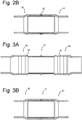
- Figure 2a schematically shows coupler 10 and a first pipe 30 and second pipe 40; and Fig. 2b shows first pipe 30 and second pipe 40 connected to coupler 10.
- Each of first pipe 30 and second pipe 40 includes first inner diameter ID PF and second inner diameter ID PS at the respective ends of first and second pipes 30, 40.
- Second inner is diameter ID PS is larger than first inner diameter ID PF .
- First and second pipes 30, 40 are formed of a plastic material, for example, polyethylene (“PE”), polyvinylchloride (“PVC”) or polypropylene (“PP").
- Coupler 10 is used to securing first pipe 30 to second pipe 40, forming a substantially constant and smooth inner diameter from first pipe 30 to second pipe 40 through coupler 10.
- the circumference at the outer ends is uninterrupted, leading to outer ends of the tubular body that are substantially planar and thereby provide for a smooth transition between the pipe inner wall and the inner wall of the tubular body.
- One or more seals 19, e.g., o-rings, can be placed in grooves 18a, 18b, though some embodiments may not use seals.
- First pipe 30 is pushed onto first portion 12 of coupler 10 until the end of first pipe 30 abuts stop edge 20. This can be done using a machine, such as a hydraulic device, for applying the proper force required to connect first pipe 30 around coupler 10.
- Second pipe 40 is then connected to second portion 14 of coupler in the same general manner.
- coupler 10 could be connected to first pipe 30 at a different location (e.g., at a manufacturing or storage facility) and only connected to second pipe 40 on location of use.
- First pipe 30 and second pipe 40 have a second inner diameter ID PS that is typically a bit smaller (e.g., 0.5%-5% smaller) than the outer diameter of the teeth OD T of coupler 10. This ensures that first and second pipes 30, 40 secure to coupler 10, with teeth 14, 24 engaging the inside of first and second pipes 30, 40 and providing a tensile tight connection without the need of additional connecting components (e.g., adhesive, gripping rings).
- the first inner diameters ID PF of pipes 30, 40 are substantially the same as the inner diameter of coupler IDc, providing a constant and smooth surface through first pipe 30, coupler 10 and second pipe 40.
- Coupler 10 through circumferential outer teeth 14, 24 provides an easy and secure way of connecting pipes 30, 40 for use together. This can be particularly useful in horizontal drilling operations and/or to protect cables in power networks. In such systems, pipes are placed and then cables are pulled through the pipes.
- the use of coupler 10 allows for a continuous pipe network with a constant and smooth inner diameter to reduce or eliminate the chance of cables getting snagged and/or damaged during installation (or removal). Additionally, the smooth constant inner diameter decreases the friction involved in pulling cables through the pipeline.
- Providing a coupler 10 with a plurality of teeth 14, 24 on the outside circumference also allows for the gripping force to increase as the pipes 30, 40 are pulled apart (as the pipe contracts when under tensile forces) thereby ensuring pipes 30, 40 stay coupled (e.g., for drilling operations and/or cable protection) even under significant tensile forces.
- Coupler 10 provides an easier and faster way to coupler pipes 30, 40 for HDD or other operations while maintaining the strong connections. Instead of requiring welding on-site with all the welding tools and supplies, a small hydraulic machine can be used to connect pipes to coupler. In some cases, coupler 10 could even be connected to one pipe at another location, for example a location of manufacture or storage. Other past couplers fit on the outside of pipes with inner gripping rings or teeth. However, such past couplers could not maintain a tight connection when deformable (e.g., PE) pipes were under tensile forces and contracting.
- PE deformable
- Coupler 10 by having gripping teeth on an outer circumference, provides a simple, reliable and secure way of ensuring pipes stay coupled together, even under tensile forces, without the need for additional gripping rings, welding or glue. Additionally, the materials of coupler 10 and pipes 30, 40 could be chosen to add (or reduce) frictional gripping force depending on the coupling strength required for the application.
- FIGs 3a-3b show coupler 10 with a further embodiment of pipes 30', 40'.
- pipes 30', 40' have complementary coupling features to secure to teeth 14, 24 of coupler 10.
- Such complementary coupling features are shown as circumferential grooves 42 on the inner diameters of pipes 30', 40' at the ends.
- Pipes 30', 40' can have equal numbers of complementary features or can have complementary features to interact with only some of the teeth 14, 24 (or other securing features) on coupler 10. While the complementary coupling features 42 are shown as grooves, they could be teeth or other structural features which can connect to features on coupler 10.
- Coupler 10 and pipes 30', 40' secure together in the same manner as those shown and described in Figs. 2a-2b .
- the additional complementary coupling features in pipes 30', 40' provide additional coupling forces, and in some cases could be used to give an indication (tactile or audio feedback) towards the coupler 10 and pipe being fully coupled together.
- Pipes (and particularly the end profiles of pipes 30, 30', 40, 40') of Figs. 2a - 3b could be formed though a number of methods, for example, hot forming combined with machining, injection moulding parts and connecting or welding to pipes, etc.
- FIG 4 shows a further embodiment of a coupler 10'.
- Coupler 10' is similar to coupler 10 shown in Figs. 1-3b , only includes on each of first portion 12 and second portion 22 seven circumferential teeth 14, 24 extending outwards. Teeth 14, 24 extend toward end stop 16, and are spaced evenly along first portion 12 and second portion 22, still leaving grooves 18a, 18b for one or more seals directly adjacent to end stop 16.
- Such a coupler 10' illustrates how different shapes, amounts, spacing, etc. of teeth 14, 24 can be used to form a coupler which will provide the correct coupling force needed. Additionally, the use of fewer teeth can enable easier manufacture and in some cases use less material.
- each tooth contributes to the same extent in transferring the tensile load from the pipe to the coupler.
- all teeth are shaped and spaced equally on the same coupler, which can lead to backup gripping should a pipe slip over one circumferential tooth on a coupler.
- couplers have been shown with two openings for receiving pipes, other embodiments of the coupler can have one or more than two openings for coupling to different numbers of pipes.
- the second portion can be, for example, a stopper to seal the pipe.
- the number and/or shape of teeth and/or complementary coupling features can differ from those shown in the Figures.
- Figures 5 and 6 show further embodiments of a coupler comprising a first and second tube secured to each other to form one tubular body. Additional features of the coupler that have already been described above with reference to the first two embodiments may also be present in the further embodiments shown in figures 5 and 6 and will not all be discussed here again. For the discussion with reference to figures 5 and 6 , like features are designated with similar reference numerals preceded by 100, to distinguish the embodiments.
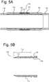
- FIG. 5A schematically shows cross-sectional view of a coupler 110 with a first pipe 130 and second pipe 140 connected to each other through the coupler 110.
- the coupler 110 comprises a first tube 150 and a second tube 160, which are connected to each other at a central portion 116 of the coupler 110.
- a sleeve 170 is provided around the central portion 116 that allows to selectively secure the first and second tube 150,160 to each other.
- the sleeve 170 comprises two or more parts that are engaged with each other using pins 180. It will be understood that other fasteners may be provided alternatively or in addition to these pins 180, for example nails, screws or bolts.
- Each of the first tube 150 and second tube 160 are provided with an outer end that is substantially planar.
- the opening defined by the outer end lies substantially within one plane.
- Figure 5B shows a cross-sectional view of the first tube 150.
- the first tube 150 has a first portion 112 to grip the pipe 130 and a mating portion 154 that is configured to together with a mating portion of the second tube 160 form the central portion 116 of the coupler 110.
- the first portion 112 comprises teeth 114, which can be arranged in any configuration as previously described in relation to the other embodiments of the coupler 10, 10'.
- the first portion 112 has a length L G of approximately 100 mm in embodiments suitable for coupling pipes of about 160 mm outer diameter, with a wall-thickness of 9.5 mm.
- the length L G indicates the length of the tube that is received within the pipe 130.
- the first tube 150 and second tube 160 are substantially identical in this embodiment. This eases the production as both the first and second tube 150, 160 can be made using the same process. Nevertheless, it will be understood that the second tube 160 may also comprise a second portion with a different number, configuration and/or shape of teeth, or have a different length L G .
- the mating portion 154 of the first tube 150 is provided with a mating surface 156 complementary to a surface of the sleeve 170 to engage with.
- the mating surface 156 comprises a groove, yet it will be understood that in embodiments the mating surface 156 may also have a different shape.
- Fig. 5C shows an exploded view of the sleeve 170.
- the sleeve 170 comprises two half cylinders 176, 178 configured to together form a sleeve around the two tubes 150, 160.
- the first half cylinder 176 has openings 174 in an outer circumferential surface for entering the pins 180 and the second half cylinder has pin openings 172 in the second half cylinder 178.
- the tubes 150, 160 can already be inserted in the pipes 130, 140 at a different location (e.g., at a manufacturing or storage facility) and therefore the assembly at location can be very easy and quick. Moreover, no special tools are required to connect the pipes 130, 140, which also makes the assembly safe to install. In addition, the coupling of the pipes 130, 140 can take place will performing the horizontal directional drilling, which may both save time as well as space.
- Figure 6 shows another embodiment of a coupler 110' comprising separate first and second tubes 150', 160' to form the tubular body.
- first portion 112' of the coupler 110' on the first tube 150' and the second portion 122' of the coupler 110' on the second tube 160' can be identical, but the mating portions 154', 164' are complementary to each other.
- the first tube is provided with a socket end portion and configured to receive a mating spigot portion of the second tube. It will be understood that various configurations involving complementary socket and spigot fittings may be used to successfully couple the tubes.
- the mating portions 154', 164' are each provided with a recess to together define a keyway 190 that is configured to house a key 190.
- a rubber seal 194 is arranged to provide a leak-free connection between the two tubes 150', 160' that form the tubular body.
- the tubes 150, 150',160, 160' are typically each made in one part, for example through injection moulding and/or machining.
- the tubes 150,150',160,160' are typically formed of a plastic material, for example, Polyoxymethylene (POM), Polyether ether ketone (PEEK), or Polyvinyl chloride (PVC); though in some cases could be formed of other materials.
- POM Polyoxymethylene
- PEEK Polyether ether ketone
- PVC Polyvinyl chloride
- coupler 10, 10', 110, 110' is able to provide a strong coupling force to one or more pipes 30, 40, 130, 140 and a smooth constant inner diameter throughout the pipeline without the need for welding or other connection pieces (and the additional time, tools and material needed for the welding or other connection pieces).
- the circumferential outer teeth on each of first and second portions 12, 22, 112, 122 connect to inner diameters of pipes 30, 40, 130, 140 to provide a strong coupling force, particularly when the pipes and/or pipeline is under tensile forces.
- the smooth, constant inner diameter through pipes and coupler provides a pathway for cables to be pulled without the risk of damage from large seams or changes in diameter, and provides for less friction when pulling the cables through.
Landscapes
- Engineering & Computer Science (AREA)
- General Engineering & Computer Science (AREA)
- Mechanical Engineering (AREA)
- Quick-Acting Or Multi-Walled Pipe Joints (AREA)
Applications Claiming Priority (1)
| Application Number | Priority Date | Filing Date | Title |
|---|---|---|---|
| NL2025033A NL2025033B1 (en) | 2020-03-03 | 2020-03-03 | A coupler for coupling to a pipe and methods of forming the coupler |
Publications (1)
| Publication Number | Publication Date |
|---|---|
| EP3875822A1 true EP3875822A1 (fr) | 2021-09-08 |
Family
ID=70918923
Family Applications (1)
| Application Number | Title | Priority Date | Filing Date |
|---|---|---|---|
| EP21160315.4A Pending EP3875822A1 (fr) | 2020-03-03 | 2021-03-02 | Coupleur pour tuyau et procédés de formation de coupleur |
Country Status (2)
| Country | Link |
|---|---|
| EP (1) | EP3875822A1 (fr) |
| NL (1) | NL2025033B1 (fr) |
Citations (6)
| Publication number | Priority date | Publication date | Assignee | Title |
|---|---|---|---|---|
| US4489963A (en) * | 1982-04-13 | 1984-12-25 | Otis Engineering Corporation | Pipe joint |
| US4597594A (en) * | 1983-09-09 | 1986-07-01 | Chris Kaye Plastics Corp. | Hose connector |
| US5516158A (en) * | 1986-07-18 | 1996-05-14 | Watts; John D. | Self-swaging threaded tubular connection |
| WO1999051908A1 (fr) * | 1998-04-07 | 1999-10-14 | Aeroquip Corporation | Raccord pour elements tubulaires |
| WO2002075198A1 (fr) * | 2001-03-15 | 2002-09-26 | David George Stark | Dispositif de raccord pivotant pour tuyaux |
| US9273811B1 (en) * | 2012-06-22 | 2016-03-01 | Jade Development, L.L.C. | Hose coupling with a separate sleeve and collar |
-
2020
- 2020-03-03 NL NL2025033A patent/NL2025033B1/en active
-
2021
- 2021-03-02 EP EP21160315.4A patent/EP3875822A1/fr active Pending
Patent Citations (6)
| Publication number | Priority date | Publication date | Assignee | Title |
|---|---|---|---|---|
| US4489963A (en) * | 1982-04-13 | 1984-12-25 | Otis Engineering Corporation | Pipe joint |
| US4597594A (en) * | 1983-09-09 | 1986-07-01 | Chris Kaye Plastics Corp. | Hose connector |
| US5516158A (en) * | 1986-07-18 | 1996-05-14 | Watts; John D. | Self-swaging threaded tubular connection |
| WO1999051908A1 (fr) * | 1998-04-07 | 1999-10-14 | Aeroquip Corporation | Raccord pour elements tubulaires |
| WO2002075198A1 (fr) * | 2001-03-15 | 2002-09-26 | David George Stark | Dispositif de raccord pivotant pour tuyaux |
| US9273811B1 (en) * | 2012-06-22 | 2016-03-01 | Jade Development, L.L.C. | Hose coupling with a separate sleeve and collar |
Also Published As
| Publication number | Publication date |
|---|---|
| NL2025033B1 (en) | 2021-10-14 |
Similar Documents
| Publication | Publication Date | Title |
|---|---|---|
| AU701403B2 (en) | Interlocked restraint for a plastic pipe joining system | |
| US12467568B2 (en) | Mechanical fitting for plastic pipe | |
| US6902205B2 (en) | Coupling for composite pipe | |
| US7845686B2 (en) | Restrained pipe joining system for plastic pipe | |
| US9822912B2 (en) | Push-to-connect fitting device, arrangement and method | |
| US6499772B1 (en) | Radial conduit coupling system and method | |
| US20150276103A1 (en) | Pipe joint | |
| AU2015314833B2 (en) | Dynamic riser mechanical connector | |
| US20080272594A1 (en) | Slip type pipe joint | |
| CA2653173A1 (fr) | Couplage sismique pvc et son procede d'installation | |
| EP3875822A1 (fr) | Coupleur pour tuyau et procédés de formation de coupleur | |
| WO2004046603A1 (fr) | Connecteur de conduite ameliore | |
| AU2006303813B2 (en) | A slip type pipe joint | |
| AU2003101082A4 (en) | Improved pipe connector | |
| AU2011101287A4 (en) | A slip type pipe joint | |
| AU2003283056A1 (en) | Improved pipe connector |
Legal Events
| Date | Code | Title | Description |
|---|---|---|---|
| PUAI | Public reference made under article 153(3) epc to a published international application that has entered the european phase |
Free format text: ORIGINAL CODE: 0009012 |
|
| STAA | Information on the status of an ep patent application or granted ep patent |
Free format text: STATUS: THE APPLICATION HAS BEEN PUBLISHED |
|
| AK | Designated contracting states |
Kind code of ref document: A1 Designated state(s): AL AT BE BG CH CY CZ DE DK EE ES FI FR GB GR HR HU IE IS IT LI LT LU LV MC MK MT NL NO PL PT RO RS SE SI SK SM TR |
|
| STAA | Information on the status of an ep patent application or granted ep patent |
Free format text: STATUS: REQUEST FOR EXAMINATION WAS MADE |
|
| 17P | Request for examination filed |
Effective date: 20220308 |
|
| RBV | Designated contracting states (corrected) |
Designated state(s): AL AT BE BG CH CY CZ DE DK EE ES FI FR GB GR HR HU IE IS IT LI LT LU LV MC MK MT NL NO PL PT RO RS SE SI SK SM TR |
|
| P01 | Opt-out of the competence of the unified patent court (upc) registered |
Effective date: 20230527 |
|
| STAA | Information on the status of an ep patent application or granted ep patent |
Free format text: STATUS: EXAMINATION IS IN PROGRESS |
|
| 17Q | First examination report despatched |
Effective date: 20230818 |