EP3875846B1 - Kraftfahrzeugscheinwerfer - Google Patents
Kraftfahrzeugscheinwerfer Download PDFInfo
- Publication number
- EP3875846B1 EP3875846B1 EP20160394.1A EP20160394A EP3875846B1 EP 3875846 B1 EP3875846 B1 EP 3875846B1 EP 20160394 A EP20160394 A EP 20160394A EP 3875846 B1 EP3875846 B1 EP 3875846B1
- Authority
- EP
- European Patent Office
- Prior art keywords
- light module
- bulge
- motor vehicle
- region
- vehicle headlamp
- Prior art date
- Legal status (The legal status is an assumption and is not a legal conclusion. Google has not performed a legal analysis and makes no representation as to the accuracy of the status listed.)
- Active
Links
Images

Classifications
-
- F—MECHANICAL ENGINEERING; LIGHTING; HEATING; WEAPONS; BLASTING
- F21—LIGHTING
- F21S—NON-PORTABLE LIGHTING DEVICES; SYSTEMS THEREOF; VEHICLE LIGHTING DEVICES SPECIALLY ADAPTED FOR VEHICLE EXTERIORS
- F21S41/00—Illuminating devices specially adapted for vehicle exteriors, e.g. headlamps
-
- F—MECHANICAL ENGINEERING; LIGHTING; HEATING; WEAPONS; BLASTING
- F21—LIGHTING
- F21S—NON-PORTABLE LIGHTING DEVICES; SYSTEMS THEREOF; VEHICLE LIGHTING DEVICES SPECIALLY ADAPTED FOR VEHICLE EXTERIORS
- F21S41/00—Illuminating devices specially adapted for vehicle exteriors, e.g. headlamps
- F21S41/20—Illuminating devices specially adapted for vehicle exteriors, e.g. headlamps characterised by refractors, transparent cover plates, light guides or filters
- F21S41/28—Cover glass
-
- F—MECHANICAL ENGINEERING; LIGHTING; HEATING; WEAPONS; BLASTING
- F21—LIGHTING
- F21S—NON-PORTABLE LIGHTING DEVICES; SYSTEMS THEREOF; VEHICLE LIGHTING DEVICES SPECIALLY ADAPTED FOR VEHICLE EXTERIORS
- F21S41/00—Illuminating devices specially adapted for vehicle exteriors, e.g. headlamps
- F21S41/20—Illuminating devices specially adapted for vehicle exteriors, e.g. headlamps characterised by refractors, transparent cover plates, light guides or filters
- F21S41/2805—Cover glass
-
- B—PERFORMING OPERATIONS; TRANSPORTING
- B60—VEHICLES IN GENERAL
- B60Q—ARRANGEMENT OF SIGNALLING OR LIGHTING DEVICES, THE MOUNTING OR SUPPORTING THEREOF OR CIRCUITS THEREFOR, FOR VEHICLES IN GENERAL
- B60Q1/00—Arrangement of optical signalling or lighting devices, the mounting or supporting thereof or circuits therefor
- B60Q1/0029—Spatial arrangement
- B60Q1/0041—Spatial arrangement of several lamps in relation to each other
-
- B—PERFORMING OPERATIONS; TRANSPORTING
- B60—VEHICLES IN GENERAL
- B60Q—ARRANGEMENT OF SIGNALLING OR LIGHTING DEVICES, THE MOUNTING OR SUPPORTING THEREOF OR CIRCUITS THEREFOR, FOR VEHICLES IN GENERAL
- B60Q1/00—Arrangement of optical signalling or lighting devices, the mounting or supporting thereof or circuits therefor
- B60Q1/02—Arrangement of optical signalling or lighting devices, the mounting or supporting thereof or circuits therefor the devices being primarily intended to illuminate the way ahead or to illuminate other areas of way or environments
- B60Q1/04—Arrangement of optical signalling or lighting devices, the mounting or supporting thereof or circuits therefor the devices being primarily intended to illuminate the way ahead or to illuminate other areas of way or environments the devices being headlights
- B60Q1/06—Arrangement of optical signalling or lighting devices, the mounting or supporting thereof or circuits therefor the devices being primarily intended to illuminate the way ahead or to illuminate other areas of way or environments the devices being headlights adjustable, e.g. remotely-controlled from inside vehicle
- B60Q1/068—Arrangement of optical signalling or lighting devices, the mounting or supporting thereof or circuits therefor the devices being primarily intended to illuminate the way ahead or to illuminate other areas of way or environments the devices being headlights adjustable, e.g. remotely-controlled from inside vehicle by mechanical means
- B60Q1/0683—Adjustable by rotation of a screw
-
- F—MECHANICAL ENGINEERING; LIGHTING; HEATING; WEAPONS; BLASTING
- F21—LIGHTING
- F21S—NON-PORTABLE LIGHTING DEVICES; SYSTEMS THEREOF; VEHICLE LIGHTING DEVICES SPECIALLY ADAPTED FOR VEHICLE EXTERIORS
- F21S41/00—Illuminating devices specially adapted for vehicle exteriors, e.g. headlamps
- F21S41/20—Illuminating devices specially adapted for vehicle exteriors, e.g. headlamps characterised by refractors, transparent cover plates, light guides or filters
- F21S41/25—Projection lenses
-
- F—MECHANICAL ENGINEERING; LIGHTING; HEATING; WEAPONS; BLASTING
- F21—LIGHTING
- F21S—NON-PORTABLE LIGHTING DEVICES; SYSTEMS THEREOF; VEHICLE LIGHTING DEVICES SPECIALLY ADAPTED FOR VEHICLE EXTERIORS
- F21S41/00—Illuminating devices specially adapted for vehicle exteriors, e.g. headlamps
- F21S41/40—Illuminating devices specially adapted for vehicle exteriors, e.g. headlamps characterised by screens, non-reflecting members, light-shielding members or fixed shades
-
- F—MECHANICAL ENGINEERING; LIGHTING; HEATING; WEAPONS; BLASTING
- F21—LIGHTING
- F21S—NON-PORTABLE LIGHTING DEVICES; SYSTEMS THEREOF; VEHICLE LIGHTING DEVICES SPECIALLY ADAPTED FOR VEHICLE EXTERIORS
- F21S41/00—Illuminating devices specially adapted for vehicle exteriors, e.g. headlamps
- F21S41/50—Illuminating devices specially adapted for vehicle exteriors, e.g. headlamps characterised by aesthetic components not otherwise provided for, e.g. decorative trim, partition walls or covers
-
- B—PERFORMING OPERATIONS; TRANSPORTING
- B60—VEHICLES IN GENERAL
- B60Q—ARRANGEMENT OF SIGNALLING OR LIGHTING DEVICES, THE MOUNTING OR SUPPORTING THEREOF OR CIRCUITS THEREFOR, FOR VEHICLES IN GENERAL
- B60Q2200/00—Special features or arrangements of vehicle headlamps
- B60Q2200/30—Special arrangements for adjusting headlamps, e.g. means for transmitting the movements for adjusting the lamps
- B60Q2200/36—Conjoint adjustments, i.e. a mechanical link allows conjoint adjustment of several units
-
- F—MECHANICAL ENGINEERING; LIGHTING; HEATING; WEAPONS; BLASTING
- F21—LIGHTING
- F21W—INDEXING SCHEME ASSOCIATED WITH SUBCLASSES F21K, F21L, F21S and F21V, RELATING TO USES OR APPLICATIONS OF LIGHTING DEVICES OR SYSTEMS
- F21W2102/00—Exterior vehicle lighting devices for illuminating purposes
- F21W2102/10—Arrangement or contour of the emitted light
- F21W2102/13—Arrangement or contour of the emitted light for high-beam region or low-beam region
Definitions
- the invention relates to a motor vehicle headlight according to the preamble of claim 1.
- the invention further relates to a motor vehicle with at least one such motor vehicle headlight, wherein the at least one motor vehicle headlight is arranged as a main headlight on a vehicle front or as a rear light on a rear side of the motor vehicle.
- Vehicle headlights in which one or more light modules are arranged in a housing of the vehicle headlight behind a lens, are well known.
- the light modules are used to generate different light distributions, for example to generate a low beam distribution, high beam distribution, daytime running light distribution, segmented light distributions, etc.
- EP 2017 154410 A shows vehicle headlights with a lens, which have a base surface with a bulge area.
- EP0512793 A2 shows a vehicle headlight, with the horizontal pivot axis of the light module running in its front area, which lies within the lens.
- the light modules are located protected behind the cover plate, which is designed to be translucent/transparent at least in some areas, usually over the entire surface.
- the cover plates can have different shapes adapted to the front of a motor vehicle, in particular curvatures defined in the horizontal and vertical directions.
- Typical cover plates are usually smooth, i.e. without structuring, but can also have structuring at least in some areas or over the entire surface.
- integration light module is only intended to express that it is a light module which is assigned to a bulge area and is arranged at least with parts or sections in “its” bulge area.
- a vehicle headlight according to the invention can also have one or more "conventional" light modules, which are located in a known manner behind the cover lens, i.e. behind the base surface of the lens in the case of a headlight according to the invention.
- the term “integration light module” thus makes a linguistic distinction between these light modules.
- front is preferably understood to mean that area etc. in which the light exit surface of a light module is located, or is preferably that area of a light module from which the light is used to generate a desired light distribution etc . exit.
- top preferably refer to an installation position of the motor vehicle headlight in a motor vehicle.
- Cover lenses from the prior art have, apart from any structuring (then also referred to as diffusers), a substantially smooth light exit surface, i.e. this has no significant elevations or indentations.
- one or more bulge areas are provided for receiving preferably at least a part of an integration light module. This can, for example, create a visual impression as if an individual light module or individual light modules were integrated directly into the front of the motor vehicle, although they are still arranged behind the cover window and protected by it.
- the entire bulge boundary surface of at least one bulge region, preferably all bulge regions, is translucent.
- the entire bulge boundary surface is designed to be translucent.
- this transparent area is at least as large as the area from which light emerges from the integration light module or as large as the emerging light cone.
- the base surface of the cover lens is designed to be opaque.
- the cover plate can be made of different materials, for example the cover plate can be made of 2 materials (2K), the bulge limiting surface or parts thereof being translucent, while the base surface is designed to be opaque. Accordingly, light from an integration light module can emerge from the headlight, but visibility into the headlight or the housing from the outside is largely prevented.
- the base surface of the cover plate is (also) designed to be translucent, and an opaque cover is preferably arranged in an interior of the housing behind the cover plate, in particular behind the base surface.
- the cover plate is easier to manufacture and can, for example, be formed in its entirety from just a single, transparent material.
- an opaque cover is useful so that the headlight cannot be seen from the outside.
- exactly one integration light module is assigned to a bulge area, ie the front part is located only in front of this one assigned integration light module in the bulge area.
- the term light module or geometric design/definition of the light module means all components of the light module or contributes all components of the light module, e.g. support elements or general mechanical components without an optical function.
- light module or geometric design/definition of the light module means all components of the light module or contributes all components of the light module, e.g. support elements or general mechanical components without an optical function.
- one or in particular all integration light modules or components of the respective integration light module can be pivoted.
- the entire integration light module is pivotable or that one integration light module is pivotable in such a way that at least or only components of the integration light module or those components of the integration light module that are located in a bulge area are pivotable.
- An integration light module or its pivotable components can be pivoted at least about one pivot axis, preferably around two pivot axes, for example only about a horizontal pivot axis or only about a vertical pivot axis, or about a vertical pivot axis and a horizontal pivot axis.
- the horizontal pivot axis of an integration light module runs transversely to an optical axis of the integration light module, in particular normal to the optical axis.
- At least one of the pivot axes preferably both pivot axes, run in a front region of the integration light module, i.e. in a region of the integration light module which lies within the bulge region.
- an integration light module can be pivoted about two pivot axes, these are preferably perpendicular to one another and preferably intersect at a point
- the at least one pivot axis, preferably all pivot axes, of an integration light module run through a vertex of this integration light module, i.e. through the frontmost point of the integration light module.
- one or each integration light module has optics, in particular imaging or projection optics, for example in the form of a lens, in particular a projection lens, or with a lens, in particular with a projection lens.
- the vertex of the lens preferably corresponds to the vertex of the integration light module.
- an opening is provided in the base surface during the transition from the base surface to a bulge area, this opening preferably being surrounded by a diaphragm, for example an annular diaphragm, the annular diaphragm being designed in the form of a partial ring or a closed ring is, or the aperture is designed in the form of a conical jacket that tapers towards the inside of the housing.
- a diaphragm for example an annular diaphragm
- the annular diaphragm being designed in the form of a partial ring or a closed ring
- the aperture is designed in the form of a conical jacket that tapers towards the inside of the housing.
- This, for example ring-shaped, aperture forms a kind of collar which is directed towards the interior of the housing. It prevents a view of the interior of the headlight.
- this aperture or each aperture is formed in one piece with the cover plate.
- that area of the integration light module, which is located in the bulge area or projects into it tapers less strongly in the light exit direction or in the direction of an optical axis, directed away from the housing, than the bulge boundary surface of the bulge area and/or tapers less than the aperture in this direction, and/or that area of the integration light module which is located in the bulge area or projects into it, in the light exit direction or in the direction of an optical axis, from the housing directed away, at least in planes on which a pivot axis is normal, tapers less than that Bulge limiting surface of the bulge area and / or tapers less than the aperture in this direction.
- a light exit surface of the integration light module for example a light exit surface of the optics, in particular projection optics or projection lens, is more curved than the bulge boundary surface of the associated bulge.
- the motor vehicle headlight comprises one or more adjustment systems, which are used to pivot at least one integration light module about at least one of its pivot axes, preferably for pivoting two or more integration light modules, in particular each about a pivot axis of the respective integration -Light module, is/are set up.
- Figure 1 shows a motor vehicle headlight 1 for a motor vehicle, the motor vehicle headlight 1 comprising a housing 2 with a housing opening 2a, which is closed by a cover plate 3.
- a motor vehicle headlight 1 comprising a housing 2 with a housing opening 2a, which is closed by a cover plate 3.
- One or more, in this specific case two, light modules 11, 12 are arranged in the housing 2 and are set up to emit light, which light can pass through the cover plate 3.
- the light modules 11, 12 are used, for example, to generate a light distribution, such as a low beam or high beam distribution, etc.
- the cover plate 3 has a base surface 3a. With a conventional lens, this base surface is translucent and the light modules sit completely in the housing behind this base surface.
- the base surface 3a can also be translucent and one or more light modules can also be arranged behind it in a known manner.
- the base surface 3a is opaque.
- the base surface 3a has one or more, in this specific case two, directed outwards from the base surface 3a (i.e. approximately curved in the direction of travel for a headlight or in the reversing direction for a rear headlight, or generally curved away from the housing). .Curved bulging areas 31, 32.
- the bulging areas 31, 32 have no openings etc., so that the cover plate 3 is a continuous element which closes the housing 2 against environmental influences like a conventional cover plate known from the prior art.
- a light module is assigned to each of these bulge areas 31, 31.
- Such light modules assigned to a bulge area 31, 32 are referred to below as “integration light module”.
- the bulge boundary surfaces 310, 320 are designed to be translucent at least in some areas, so that light emitted by an integration light module 11, 12 can emerge through the cover plate 3. It can also be provided that the entire bulge boundary surface 310, 320 is designed to be translucent.
- the corresponding openings/recesses in the base surface 3a are each surrounded by an annular aperture 31b, 32b, the annular aperture 31b, 32b in Formed in the form of a partial ring or, as shown, in the form of a closed ring or in the form of a conical jacket that tapers towards the inside of the housing.
- This e.g. annular cover 31b, 32b forms a kind of collar which is directed towards the interior of the housing. It prevents a view of the interior of the headlight.
- FIG. 2 shows two such integration light modules 11, 12, which are arranged in the housing 2 behind their respective bulge area 31, 32.
- An integration light module 31, 31 is characterized in that it is arranged in the vehicle headlight 1 in such a way that at least a part, in particular a front part, of the integration light module 11, 12 protrudes into its bulge area 31, 32.
- the bulge area 31, 32, into which an integration light module 11, 12 protrudes, is geometrically determined in such a way that components of the integration light module 11, 12 protruding into the bulge area 31, 32 are at a distance greater than zero from the bulge area 31 , 32 defining or limiting bulge limiting surface 310, 320 ( Figure 1 ) condition.
- Figure 3 shows, for example, in a vertical section (plane BB).
- Figure 2 a front part 111 of the integration light module 11, which protrudes into the bulge region 31 delimited by the bulge boundary surface 310.
- an integration light module 31, 32 comprises in a front area an optic, in particular a projection optics or projection lens 11b, 12b, which emits light from a light source (not shown; for example one or more LEDs), optionally after shaping is emitted by further optical elements (reflector, light guide, etc.) from the projection lens 11b, 12b in the form of a light beam to form a desired light distribution.
- a light source not shown; for example one or more LEDs
- further optical elements reflector, light guide, etc.
- At least one such optic in particular projection lens 11b, 12b, is to be understood by the term "front part of the integration light module", i.e. it is located in the respective bulge area 31, 32.
- an integration light module 11, 12, for example holding elements (such as lens carriers) can also protrude into the bulge area 31, 32 and then fall under the term “front part”.
- the front part of the integration light module 11 has a distance greater than zero from the bulge limiting surface 310 on all sides, i.e. towards the front, above and below and laterally, this distance preferably being kept as small as possible.
- the integration light modules 11, 12 are pivotably mounted in the vehicle headlight 1.
- an integration light module can be pivoted to set a basic position, for example manually, or that the integration light modules can be pivoted dynamically, ie depending on the driving status of the motor vehicle. A combined adjustment is also possible.
- FIG 2 a mechanical pivoting of the two integration light modules 11, 12 is shown in each case about a horizontal pivot axis HH11 and a vertical pivot axis VV11, VV12 per integration light module 11, 12, with the pivot axes HH11, VV11, VV12 in the Figures 3 and 4 can be recognized.
- the pivoting axes of an integration light module are preferably normal to one another and preferably intersect, the horizontal pivoting axes HH11 typically run normally on an optical axis X11, X12 of the respective integration light module 11, 12.
- Figure 2 shows a first combined adjustment system 200 - 204, comprising a rotating element 200, which, for example, is rotatably mounted in the housing 2 about its longitudinal axis and, for example, has a tool holder for a screwdriver or the like, which is accessible from the outside.
- a twisting movement of the rotary element 200 is transmitted to a coupling element 201 via a thread arrangement 202, the rotary movement of the rotary element 200 being converted into a translational movement of the Coupling element 201 is implemented.
- the coupling element 201 is connected to a coupling arrangement 203 with the integration light module 11, specifically with a holding element 211 for the integration light module 11 and with a coupling arrangement 204 with the integration light module 12, specifically with a holding element 212 for the integration light module 12 .
- a translational movement of the coupling element 201 leads to a pivoting movement of the two integration light modules 11, 12 about their respective horizontal pivoting axis, of which only one is Figure 3 , provided there with the reference number HH11, is shown.
- the integration light modules 11, 12 are thus pivoted in the vertical direction, ie up or down.
- a coupling arrangement 203, 204 can each be formed, for example, from a ball head, which is guided in a guide, which is designed, for example, in the form of a slotted partial cylinder, so that in particular pivoting of both integration light modules 11, 12 is possible without jamming.
- the guide is part of a spherical cap that is fixedly connected, for example screwed, to the support frame 211, 212 of the integration light module and is curved in two directions corresponding to the adjustment paths of the respective integration light module.
- the adjustment ranges are in Figures 3 and 4 shown in dashed lines and designated by the reference symbols ZV11 and ZH11 and ZH12 in dashed lines.
- Figure 2 further shows a second combined adjustment system 300 - 305, comprising a rotating element 300, which is rotatably mounted in the housing 2 about its longitudinal axis and, for example, has a tool holder for a screwdriver or the like, which is accessible from the outside.
- a rotational movement of the rotating element 300 is transmitted to a coupling element 301 via a thread arrangement 302 (a counter thread for a thread arranged on the rotating element 300 is arranged in a holder 305, which is firmly connected to the housing 2 or is formed in one piece with it), whereby the rotary movement of the rotary element 300 is converted into a translational movement of the coupling element 301.
- the coupling element 301 is connected to a coupling arrangement 303 with the integration light module 11, specifically with a holding element 211 for the integration light module 11, and with a coupling arrangement 304 with the integration light module 12, specifically with a holding element 212 for the integration light module 12 .
- a translational movement of the coupling element 301 leads to a pivoting movement of the two integration light modules 11, 12 about their respective vertical pivoting axis VV11, VV12.
- the integration light modules 11, 12 are thus pivoted in the horizontal direction, ie to the left or right.
- a coupling arrangement 303, 304 can each be formed, for example, from a ball head, which is guided in a guide which is designed in the form of a slotted partial cylinder, so that in particular pivoting of both integration light modules 11, 12 is possible without jamming.
- the respective integration light module 11, 12 is arranged with the smallest possible distance from its bulge boundary surface 311, 312.
- the one or more pivot axes of an integration light module 11, 12 are in a front area of the integration light module 11, 12, i.e. in an area of the integration Light module 11, 12, which lies within the bulge area 31, 32, runs or runs.
- the pivot axis(s) HH11, VV11, VV12 of an integration light module 11, 12 run through a vertex S of this integration light module, i.e. through the frontmost point of the integration light module.
- the apex or frontmost point of the integration light module 11, 12 is at the same time the apex S11, S12 of the respective projection device/lens 11b , 12b.
- a light exit surface of the integration light module for example a light exit surface of the optics, in particular the projection optics or the projection lens 11b, 12b, is more curved than the bulge limiting surface 310, 320 of the associated bulge 31, 32 .
- a virtual pivot point (pivot axis) is placed in the apex of the lens.
- pivoting was described above using two adjustment systems, which combine two integration light modules to pivot around one axis each.
- a pivoting system is only provided for pivoting about an axis of an integration light module.
- the example shown shows a vehicle headlight with two integration light modules.
- two integration light modules can also be provided that only one such integration light module but also that several such integration light modules are provided in a correspondingly designed headlight.
- the arrangement of conventional light modules behind the base surface is also conceivable in principle, but not shown here.
Landscapes
- Engineering & Computer Science (AREA)
- General Engineering & Computer Science (AREA)
- Mechanical Engineering (AREA)
- Non-Portable Lighting Devices Or Systems Thereof (AREA)
Description
- Die Erfindung betrifft einen Kraftfahrzeugscheinwerfer gemäß dem Oberbegriff von Anspruch 1.
- Weiters betrifft die Erfindung ein Kraftfahrzeug mit zumindest einem solchen Kraftfahrzeugscheinwerfer, wobei der zumindest eine Kraftfahrzeugscheinwerfer als Hauptscheinwerfer an einer Fahrzeugfront oder als Rückleuchte an einer Hinterseite des Kraftfahrzeuges angeordnet ist.
- Fahrzeugscheinwerfer, bei welchen in einem Gehäuse des Fahrzeugscheinwerfers, hinter einer Abschlussscheibe ein oder mehrere Lichtmodule angeordnet sind, sind hinlänglich bekannt. Die Lichtmodule dienen zur Erzeugung unterschiedlicher Lichtverteilungen, beispielsweise zur Erzeugung einer Abblendlichtverteilung, Fernlichtverteilung, Tagfahrlichtverteilung, segmentierten Lichtverteilungen usw.
- Fahrzeugscheinwerfer mit einem Auswölbungsbereich sind aus
US 2017/350567 A1 bekannt. - Die Veröffentlichungen
JP 2014 154410 A EP 2 623 370 A2 zeigen Fahrzeugscheinwerfer mit einer Abschlussscheibe, welche eine Basisfläche mit einem Auswölbungsbereich aufweisen.EP0512793 A2 zeigt einen Fahrzeugscheinwerfer, wobei die horizontale Verschwenkachse des Lichtmoduls in seinem vorderen Bereich, welcher innerhalb der Abschlussscheibe liegt, verläuft. - Die Lichtmodule befinden sich geschützt hinter der zumindest bereichsweise, in der Regel ganzflächig lichtdurchlässig/transparent ausgebildeten Abschlussscheibe. Typischerweise können die Abschlussscheiben unterschiedliche, an eine Kraftfahrzeugfront angepasste Formen, insbesondere in horizontaler und vertikaler Richtung definierte Krümmungen aufweisen. Zumeist sind typische Abschlussscheiben glatt, also ohne Strukturierung ausgebildet, können aber auch zumindest bereichsweise, aber auch vollflächig eine Strukturierung aufweisen.
- Es ist eine Aufgabe der Erfindung, eine Möglichkeit zu schaffen, dass bei einem Verschwenken keine Teile des Lichtmoduls an einer Auswölbungsbegrenzungsfläche zur Anlage kommen.
- Diese Aufgabe wird mit einem eingangs genannten Kraftfahrzeugscheinwerfer mit den technischen Merkmalen des Kennzeichens des Anspruchs 1 gelöst.
- Der Begriff "Integrations-Lichtmodul" soll dabei lediglich zum Ausdruck bringen, dass es sich um ein Lichtmodul handelt, welches einem Auswölbungsbereich zugeordnet ist und zumindest mit Teilen bzw. Abschnitten in "seinem" Auswölbungsbereich angeordnet ist. Grundsätzlich kann ein erfindungsgemäßer Fahrzeugscheinwerfer auch noch ein oder mehrere "herkömmliche" Lichtmodule aufweisen, die sich in bekannter Weise hinter der Abdeckscheibe, bei einem erfindungsgemäßen Scheinwerfer also hinter der Basisfläche der Abschlussscheibe befinden. Mit dem Begriff "Integrations-Lichtmodul" wird somit eine sprachliche Unterscheidung zwischen diesen Lichtmodulen vorgenommen.
- Unter dem Begriff "Vorne", "vorderer Bereich" etc. ist vorzugsweise jener Bereich etc. zu verstehen, in dem die Lichtaustrittsfläche eines Lichtmoduls liegt, bzw. liegt dort vorzugsweise jener Bereich eines Lichtmoduls, aus welchem das Licht zur Erzeugung einer gewünschten Lichtverteilung etc. austritt. Die Begriffe "oben", "unten", etc. beziehen vorzugsweise sich auf eine Einbaulage des Kraftfahrzeugscheinwerfers in einem Kraftfahrzeug.
- Abschlussscheiben aus dem Stand der Technik weisen abgesehen von allfälligen Strukturierungen (dann auch als Streuscheiben bezeichnet) eine im Wesentlichen glatte Lichtaustrittsfläche auf, d.h. diese weist keine signifikanten Erhebungen oder Einbuchtungen auf.
- Bei der vorliegenden Erfindung hingegen sind ein oder mehrere Auswölbungsbereiche zur Aufnahme vorzugsweise zumindest eines Teiles eines Integrations-Lichtmoduls vorgesehen. Dadurch kann z.B. erreicht werden, dass ein optischer Eindruck entsteht, als ob ein einzelnes Lichtmodul oder einzelne Lichtmodule direkt in die Kraftfahrzeugfront integriert wären, obwohl diese nach wie vor hinter der Abschlussscheibe und von dieser geschützt angeordnet sind.
- Es kann vorgesehen sein, dass die gesamte Auswölbungsbegrenzungsfläche zumindest eines Auswölbungsbereiches, vorzugsweise aller Auswölbungsbereiche lichtdurchlässig ist.
- Es kann, insbesondere fertigungstechnisch, von Vorteil sein, wenn die gesamte Auswölbungsbegrenzungsfläche lichtdurchlässig ausgebildet ist. Es kann aber auch vorgesehen sein, dass nur ein jener Bereich der Auswölbungsbegrenzungsfläche vor dem Integrations-Lichtmodul bzw. einer Optik, etwa einer Projektionslinse des Integrations-Lichtmodul, transparent ist, auf welchen aus dem Integrations-Lichtmodul austretendes Licht auftrifft. Je näher das Integrations-Lichtmodul an der Abschlussscheibe, d.h. an der Auswölbungsbegrenzungsfläche angeordnet ist, umso kleiner kann dieser transparente Bereich sein. Vorzugsweise ist dieser transparente Bereich zumindest so groß wie der Bereich, aus dem Licht aus dem Integrations-Lichtmodul austritt bzw. so groß wie der austretende Lichtkegel.
- Es kann vorgesehen sein, dass die Basisfläche der Abschlussscheibe lichtundurchlässig ausgebildet ist. Dazu kann z.B. die Abschlussscheibe aus unterschiedlichen Materialen hergestellt sein, z.B. kann die Abschlussscheibe aus 2 Materialien (2K) gefertigt sein, wobei die Auswölbungsbegrenzungsfläche oder Teile davon lichtdurchlässig sind, während die Basisfläche lichtundurchlässig ausgebildet ist. Entsprechend kann Licht eines Integrations-Lichtmoduls aus dem Scheinwerfer austreten, von Außen ist aber eine Einsicht in den Scheinwerfer bzw. in das Gehäuse hinein weitestgehend verhindert.
- Es kann aber auch vorgesehen sein, dass die Basisfläche der Abschlussscheibe (auch) lichtdurchlässig ausgebildet ist, und wobei vorzugsweise in einem Inneren des Gehäuses hinter der Abdeckscheibe, insbesondere hinter der Basisfläche eine lichtundurchlässige Blende angeordnet ist.
- In diesem Fall ist die Abschlussscheibe einfacher herzustellen und kann z.B. in ihrer Gesamtheit lediglich aus einem einzigen, transparenten Material gebildet sein. In diesem Fall ist eine lichtundurchlässige Blende zweckmäßig, sodass von Außen kein Einblick in den Scheinwerfer gegeben ist.
- Vorzugsweise ist einem Auswölbungsbereich genau ein Integrations-Lichtmodul zugeordnet, d.h. es befindet sich der vordere Teil lediglich vor diesem einen, zugeordneten Integrations-Lichtmodul in dem Auswölbungsbereich.
- Unter Lichtmodul bzw. geometrische Auslegung/Definition des Lichtmoduls werden alle Bestandteile des Lichtmoduls verstanden bzw. tragen alle Bestandteile des Lichtmoduls, z.B. auch Trägerelemente oder generell mechanische Bestandteile ohne optische Funktion bei. Zur dynamischen Verstellung der Ausrichtung des emittierten Lichtbündels und/oder zur Einstellung einer Grundposition ist vorzugsweise vorgesehen, dass ein oder insbesondere alle Integrations-Lichtmodule oder jeweils Bestandteile des jeweiligen Integrations-Lichtmoduls verschwenkbar sind.
- Es ist vorgesehen, dass das gesamte Integrations-Lichtmodul verschwenkbar ist oder ein Integrations-Lichtmodul jeweils derart verschwenkbar ist, dass zumindest oder lediglich Bestandteile des Integrations-Lichtmoduls oder jene Bestandteile des Integrations-Lichtmoduls, die sich in einem Auswölbungsbereiche befinden, verschwenkbar sind.
- Dabei ist ein Integrations-Lichtmodul oder seine verschwenkbaren Bestandteile zumindest um eine Verschwenkachse, vorzugsweise um zwei Verschwenkachsen, z.B. lediglich um eine horizontale Verschwenkachse oder lediglich um eine vertikale Verschwenkachse, oder um eine vertikale Verschwenkachse und eine horizontale Verschwenkachse verschwenkbar ist/ sind.
- Insbesondere kann vorgesehen sein, dass die horizontale Verschwenkachse eines Integrations-Lichtmoduls quer zu einer optischen Achse des Integrations-Lichtmoduls, insbesondere normal zu der optischen Achse verläuft.
- Zumindest eine der Verschwenkachsen, vorzugsweise beide Verschwenkachsen verlaufen in einem vorderen Bereich des Integrations-Lichtmoduls, d.h. in einem Bereich des Integrations-Lichtmoduls, welcher innerhalb des Auswölbungsbereiches liegt.
- Wenn ein Integrations-Lichtmodul um zwei Verschwenkachsen verschwenkbar ist, stehen diese vorzugsweise normal aufeinander und vorzugsweise schneiden sie sich in einem Punkt
- Die zumindest eine Verschwenkachse, vorzugsweise alle Verschwenkachsen eines Integrations-Lichtmoduls verlaufen durch einen Scheitelpunkt dieses Integrations-Lichtmoduls, d.h. durch den vordersten Punkt des Integrations-Lichtmoduls.
- Beispielsweise ist vorgesehen, dass ein bzw. jedes Integrations-Lichtmodul eine Optik, insbesondere eine Abbildungs- bzw. Projektionsoptik, etwa in Form einer Linse, insbesondere einer Projektionslinse, oder mit einer Linse, insbesondere mit einer Projektionslinse aufweist.
- In diesem Fall entspricht vorzugsweise der Scheitelpunkt der Linse (Projektionslinse) dem Scheitelpunkt des Integrations-Lichtmoduls.
- Weiters ist es günstig, wenn beim Übergang von der Basisfläche in einen Auswölbungsbereich eine Öffnung in der Basisfläche vorgesehen ist, wobei vorzugsweise diese Öffnung von einer Blende, etwa einer ringförmigen Blende umgeben ist, wobei die ringförmige Blende in Form eines Teilringes oder eines geschlossenen Ringes ausgebildet ist, oder die Blende in Form eines in Richtung Gehäuseinnerem sich verjüngenden Kegelmantel ausgebildet ist.
- Diese, beispielsweise ringförmige, Blende bildet eine Art Kragen, welche in Richtung des Gehäuseinneren gerichtet ist. Sie verhindert einen Einblick in das Innere des Scheinwerfers. Vorzugsweise ist diese Blende bzw. jede Blende mit der Abschlussscheibe einstückig ausgebildet.
- Weiters ist mit Vorteil vorgesehen, dass sich jener Bereich des Integrations-Lichtmoduls, welcher sich in dem Auswölbungsbereich befindet bzw. in diesen hineinragt, in Lichtaustrittsrichtung bzw. in Richtung einer optischen Achse, von dem Gehäuse weggerichtet, weniger stark verjüngt als die Auswölbungsbegrenzungsfläche des Auswölbungsbereiches und/oder sich weniger stark verjüngt als die Blende in dieser Richtung, und/oder sich jener Bereich des Integrations-Lichtmoduls, welcher sich in dem Auswölbungsbereich befindet bzw. in diesen hineinragt, in Lichtaustrittsrichtung bzw. in Richtung einer optischen Achse, von dem Gehäuse weggerichtet, zumindest in Ebenen, auf welche eine Verschwenkachse normal steht, weniger stark verjüngt als die Auswölbungsbegrenzungsfläche des Auswölbungsbereiches und/oder sich weniger stark verjüngt als die Blende in dieser Richtung.
- Auf diese Weise kann sichergestellt werden, dass bei einem Verschwenken keine Teile des Lichtmoduls an den Auswölbungsbegrenzungsfläche zur Anlage kommen.
- Weiters kann mit Vorteil aus den oben genannten Gründen vorgesehen, dass eine Lichtaustrittsfläche des Integrations-Lichtmoduls, beispielsweise eine Lichtaustrittsfläche der Optik, insbesondere Projektionsoptik bzw. Projektionslinse stärker gekrümmt ist als die Auswölbungsbegrenzungsfläche der zugeordneten Auswölbung.
- Zweckmäßig ist es, wenn der Kraftfahrzeugscheinwerfer ein oder mehrere Verstellsysteme umfasst, welches bzw. welche zum Verschwenken von zumindest einem Integrations-Lichtmodul um zumindest eine seiner Verschwenkachsen, vorzugsweise zum Verschwenken von zwei oder mehreren Integrations-Lichtmodulen, insbesondere jeweils um eine Verschwenkachse des jeweiligen Integrations-Lichtmoduls, eingerichtet ist/ sind.
- Im Folgenden ist die Erfindung an Hand der Zeichnung näher erläutert. In dieser zeigt
-
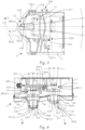
Fig. 1 einen erfindungsgemäßen Fahrzeugscheinwerfer in einer perspektivischen Frontansicht auf die Abdeckscheibe des Fahrzeugscheinwerfers mit Auswölbungsbereichen, -
Fig. 2 eine Rückansicht des inFigur 1 gezeigten Teils eines Fahrzeugscheinwerfers mit zwei Integrations-Lichtmodulen, -
Fig. 3 einen Vertikalschnitt mit eingezeichneter Drehachse durch den Aufbau ausFigur 1 und 2 , und -
Fig. 4 einen Horizontalschnitt durch den Aufbau aufFigur 1 und 2 . -
Figur 1 zeigt einen Kraftfahrzeugscheinwerfer 1 für ein Kraftfahrzeug, wobei der Kraftfahrzeugscheinwerfer 1 ein Gehäuse 2 mit einer Gehäuseöffnung 2a umfasst, welche von einer Abschlussscheibe 3 abgeschlossen ist. In dem Gehäuse 2 sind ein oder mehrere, im konkreten Fall zwei Lichtmodule 11, 12 angeordnet, welche zur Emission von Licht eingerichtet sind, welches Licht durch die Abschlussscheibe 3 durchtreten kann. - Die Lichtmodule 11, 12 dienen beispielsweise zur Erzeugung einer Lichtverteilung, wie einer Abblend- oder Fernlichtverteilung etc.
- Die Abschlussscheibe 3 weist eine Basisfläche 3a auf. Bei einer herkömmlichen Abschlussscheibe ist diese Basisfläche lichtdurchlässig und die die Lichtmodule sitzen vollständig im Gehäuse hinter dieser Basisfläche.
- Bei der vorliegenden Erfindung kann die Basisfläche 3a auch lichtdurchlässig sein und es können hinter dieser auch in bekannter Weise ein oder mehrere Lichtmodule angeordnet sein.
- Es kann bei der vorliegenden Erfindung aber auch vorgesehen sein, dass die Basisfläche 3a lichtundurchlässig ist.
- In jedem Fall verfügt die Basisfläche 3a über eine oder mehrere, im konkreten Fall zwei von der Basisfläche 3a nach Außen (also z.B. in etwa in Fahrtrichtung bei einem Frontscheinwerfer oder in Rückfahrrichtung bei einem Heckscheinwerfer gewölbt, oder generell von dem Gehäuse weg gewölbt) gerichtete bzw. gewölbte Auswölbungsbereiche 31, 32. Die Auswölbungsbereiche 31, 32 weisen dabei keine Öffnungen etc. auf, sodass die Abschlussscheibe 3 ein durchgehendes Element ist, welches das Gehäuse 2 gegen Umwelteinflüsse wie eine herkömmliche, aus dem Stand der Technik bekannte Abschlussscheibe abschließt.
- Jedem dieser Auswölbungsbereiche 31, 31 ist ein Lichtmodul zugeordnet. Solche einem Auswölbungsbereich 31, 32 zugeordnete Lichtmodule werden im Folgenden als "Integrations-Lichtmodul" bezeichnet.
- Die Auswölbungsbegrenzungsflächen 310, 320 sind zumindest bereichsweise lichtdurchlässig ausgebildet ist, sodass von einem Integrations-Lichtmodul 11, 12 emittiertes Licht durch die Abschlussscheibe 3 austreten kann. Es kann auch vorgesehen sein, dass jeweils die gesamte Auswölbungsbegrenzungsfläche 310, 320 lichtdurchlässig ausgebildet ist.
- Vorzugsweise sind beim Übergang von der Basisfläche 3a in einen jeweiligen Auswölbungsbereich 31, 32 die entsprechenden Öffnungen/ Ausnehmungen in der Basisfläche 3a, welche in den jeweiligen Auswölbungsbereich münden, jeweils von einer ringförmigen Blende 31b, 32b umgeben, wobei die ringförmige Blende 31b, 32b in Form eines Teilringes oder wie gezeigt in Form eines geschlossenen Ringes oder in Form eines sich in Richtung Gehäuseinnerem verjüngender Kegelmantel ausgebildet ist. Diese z.B. ringförmige Blende 31b, 32b bildet eine Art Kragen, welche in Richtung des Gehäuseinneren gerichtet ist. Sie verhindert einen Einblick in das Innere des Scheinwerfers.
-
Figur 2 zeigt zwei solcher Integrations-Lichtmodule 11, 12, welche in dem Gehäuse 2 hinter ihrem jeweiligen Auswölbungsbereich 31, 32 angeordnet sind. Ein Integrations-Lichtmodul 31, 31 zeichnet sich dabei jeweils dadurch aus, dass es derart in dem Fahrzeugscheinwerfer 1 angeordnet ist, dass zumindest ein Teil, insbesondere ein vorderer Teil des Integrations-Lichtmoduls 11, 12 in seinen Auswölbungsbereich 31, 32 hinein ragt. - Dabei ist der Auswölbungsbereich 31, 32, in welchen ein Integrations-Lichtmodul 11, 12 hineinragt, geometrisch derart bestimmt, dass in den Auswölbungsbereich 31, 32 hineinragende Bestandteile des Integrations-Lichtmoduls 11, 12 sich in einem Abstand größer Null zu einer den Auswölbungsbereich 31, 32 definierenden bzw. begrenzenden Auswölbungsbegrenzungsfläche 310, 320 (
Figur 1 ) befinden. -
Figur 3 zeigt z.B. in einem Vertikalschnitt (Ebene B-B ausFigur 2 ) einen vorderen Teil 111 des Integrations-Lichtmoduls 11, der in den von der Auswölbungsbegrenzungsfläche 310 begrenzten Auswölbungsbereich 31 hineinragt. - In den gezeigten Beispielen umfasst ein Integrations-Lichtmodul 31, 32 in einem vorderen Bereich jeweils eine Optik, insbesondere eine Projektionsoptik oder Projektionslinse 11b, 12b, welche Licht, welches von einer Lichtquelle (nicht dargestellt; beispielsweise ein oder mehrere LED's), gegebenenfalls nach Umformung durch weitere optische Elemente (Reflektor, Lichtleiter, etc.) von der Projektionslinse 11b, 12b in Form eines Lichtbündels zur Bildung einer gewünschten Lichtverteilung abgestrahlt wird.
- Zumindest eine solche Optik, insbesondere Projektionslinse 11b, 12b ist unter dem Begriff "vorderer Teil des Integrations-Lichtmoduls" zu verstehen, diese befindet sich also in dem jeweiligen Auswölbungsbereich 31, 32.
- Weitere zusätzliche Bestandteile eines Integrations-Lichtmoduls 11, 12, beispielsweise auch Halteelemente (etwa Linsenträger) können gegebenenfalls auch in den Auswölbungsbereich 31, 32 ragen und fallen dann unter Begriff "vorderer Teil".
- Wie man in
Figur 3 gut erkennen kann, weist der vordere Teil des Integrations-Lichtmoduls 11 zu allen Seiten, also nach Vorne, oben und unten sowie seitlich einen Abstand größer Null zu der Auswölbungsbegrenzungsfläche 310 auf, wobei dieser Abstand vorzugsweise so gering wie möglich gehalten wird. - Nochmals zurückkommend auf
Figur 2 ist zu erkennen, dass die Integrations-Lichtmodule 11, 12 verschwenkbar in dem Fahrzeugscheinwerfer 1 gelagert sind. Prinzipiell ist es denkbar, dass ein Integrations-Lichtmodul dabei zur Einstellung einer Grundposition, z.B. manuell, verschwenkbar ist, oder dass die Integrations-Lichtmodule dynamisch, d.h. abhängig vom Fahrzustand des Kraftfahrzeuges verschwenkt werden. Auch eine kombinierte Verstellung ist möglich. - In
Figur 2 ist ein mechanisches Verschwenken der beiden Integrations-Lichtmodule 11, 12 jeweils um eine horizontale Verschwenkachse HH11 und eine vertikale Verschwenkachse VV11, VV12 pro Integrations-Lichtmodul 11, 12 dargestellt, wobei die Verschwenkachsen HH11, VV11, VV12 in denFiguren 3 und 4 zu erkennen sind. Die Verschwenkachsen eines Integrations-Lichtmodul stehen dabei vorzugsweise normal aufeinander und schneiden einander bevorzugt, die horizontalen Verschwenkachsen HH11 verlaufen typischer Weise normal auf eine optische Achse X11, X12 des jeweiligen Integrations-Lichtmodul 11, 12.Figur 2 zeigt dabei ein erstes kombiniertes Verstellsystem 200 - 204, umfassend ein Drehelement 200, welche z.B. in dem Gehäuse 2 um seine Längsachse drehbar gelagert ist und beispielsweise eine Werkzeugaufnahme etwa für einen Schraubenzieher o.ä. aufweist, welche von Außen zugänglich ist. Eine Verdrehbewegung des Drehelementes 200 wird über eine Gewindeanordnung 202 auf ein Koppelelement 201 übertragen, wobei die Drehbewegung des Drehelementes 200 in eine translatorische Bewegung des Koppelelementes 201 umgesetzt wird. Das Koppelelement 201 ist mit einer Koppelanordnung 203 mit dem Integrations-Lichtmodul 11, konkret mit einem Halteelemente 211 für das Integrations-Lichtmodul 11 und mit einer Koppelanordnung 204 mit dem Integrations-Lichtmodul 12, konkret mit einem Halteelemente 212 für das Integrations-Lichtmodul 12 verbunden. Eine translatorische Bewegung des Koppelelementes 201 führt zu einer Verschwenkbewegung des beiden Integrations-Lichtmodul 11, 12 um ihre jeweilige horizontale Verschwenkachse, von welchen lediglich eine inFigur 3 , dort mit dem Bezugszeichen HH11 versehen, dargestellt ist. Die Integrations-Lichtmodule 11, 12 werden somit in vertikaler Richtung, d.h. auf oder ab, verschwenkt. Eine Koppelanordnung 203, 204 kann dabei jeweils z.B. aus einem Kugelkopf gebildet sein, der in einer Führung, welche z.B. in Form eines geschlitzten Teilzylinders ausgebildet ist, geführt ist, sodass insbesondere ein Verschwenken von beiden Integrations-Lichtmodulen 11, 12 ohne Verklemmen möglich ist. Die Führung ist dabei Teil einer Kalotte, die mit dem Tragrahmen 211, 212 des Integrations-Lichtmoduls fix verbunden, z.B. verschraubt ist und in zwei Richtungen entsprechend den Verstellwegen des jeweiligen Integrations-Lichtmoduls gekrümmt sind. Die Verstellwege sind inFigur 3 und 4 strichliert dargestellt und mit den Bezugszeichen ZV11 sowie ZH11 und ZH12 strichliert bezeichnet. -
Figur 2 zeigt weiters ein zweites kombiniertes Verstellsystem 300 - 305, umfassend ein Drehelement 300, welche z.B. in dem Gehäuse 2 um seine Längsachse drehbar gelagert ist und beispielsweise eine Werkzeugaufnahme etwa für einen Schraubenzieher o.ä. aufweist, welche von Außen zugänglich ist. Eine Verdrehbewegung des Drehelementes 300 wird über eine Gewindeanordnung 302 (ein Gegengewinde für ein auf Drehelement 300 angeordnetes Gewinde ist in einer Halterung 305, die mit dem Gehäuse 2 fest verbunden ist oder einstückig mit diesem ausgebildet ist, angeordnet) auf ein Koppelelement 301 übertragen, wobei die Drehbewegung des Drehelementes 300 in eine translatorische Bewegung des Koppelelementes 301 umgesetzt wird. Das Koppelelement 301 ist mit einer Koppelanordnung 303 mit dem Integrations-Lichtmodul 11, konkret mit einem Halteelemente 211 für das Integrations-Lichtmodul 11 und mit einer Koppelanordnung 304 mit dem Integrations-Lichtmodul 12, konkret mit einem Halteelemente 212 für das Integrations-Lichtmodul 12 verbunden. Eine translatorische Bewegung des Koppelelementes 301 führt zu einer Verschwenkbewegung des beiden Integrations-Lichtmodul 11, 12 um ihre jeweilige vertikale Verschwenkachse VV11, VV12. - Die Integrations-Lichtmodule 11, 12 werden somit in horizontaler Richtung, d.h. nach links oder rechts, verschwenkt.
- Eine Koppelanordnung 303, 304 kann dabei jeweils z.B. aus einem Kugelkopf gebildet sein, der in einer Führung, welche in Form eines geschlitzten Teilzylinders ausgebildet ist, geführt ist, sodass insbesondere ein Verschwenken von beiden Integrations-Lichtmodulen 11, 12 ohne Verklemmen möglich ist.
- Bevorzugt ist vorgesehen, dass das jeweilige Integrations-Lichtmodul 11, 12 mit möglichst geringem Abstand zu seiner Auswölbungsbegrenzungsfläche 311, 312 angeordnet ist. Um ein unbehindertes Verschwenken des Integrations-Lichtmoduls 11, 12 zu erlauben, ist vorgesehen, dass die eine oder die mehreren Verschwenkachsen eines Integrations-Lichtmoduls 11, 12 in einem vorderen Bereich des Integrations-Lichtmoduls 11, 12, d.h. in einem Bereich des Integrations-Lichtmoduls 11, 12, welcher innerhalb des Auswölbungsbereiches 31, 32 liegt, verläuft bzw. verlaufen. Insbesondere ist es in diesem Zusammenhang günstig, wenn die Verschwenkachse(n) HH11, VV11, VV12 eines Integrations-Lichtmoduls 11, 12 durch einen Scheitelpunkt S dieses Integrations-Lichtmoduls, d.h. durch den vordersten Punkt des Integrations-Lichtmoduls, verlaufen.
- Bei einem Integrations-Lichtmodul 11, 12 mit einer Optik, insbesondere einer Projektionsoptik bzw. Projektionslinse 11b, 12b wie gezeigt ist der Scheitelpunkt bzw. vorderste Punkt des Integrations-Lichtmoduls 11, 12 gleichzeitig der Scheitelpunkt S11, S12 der jeweiligen Projektionsvorrichtung/-linse 11b, 12b.
- Außerdem ist es zweckmäßig, wenn wie in
Figuren 3 und 4 gezeigt, vorgesehen ist, dass sich jener Bereich des Integrations-Lichtmoduls 11, 12, welcher sich in dem Auswölbungsbereich 31, 32 befindet bzw. in diesen hineinragt, in Lichtaustrittsrichtung X bzw. in Richtung einer optischen Achse X11, X12, von dem Gehäuse 2 weggerichtet, weniger stark verjüngt als die Auswölbungsbegrenzungsfläche 310, 320 des Auswölbungsbereiches 31, 32 und/oder sich weniger stark verjüngt als die Blende 31b, 32b in dieser Richtung, und/oder sich jener Bereich des Integrations-Lichtmoduls 11, 12, welcher sich in dem Auswölbungsbereich 31, 32 befindet bzw. in diesen hineinragt, in Lichtaustrittsrichtung X bzw. in Richtung einer optischen Achse X11, X12, von dem Gehäuse 2 weggerichtet, zumindest in Ebenen, auf welche eine Verschwenkachse HH11; VV11, VV12 normal steht, weniger stark verjüngt als die Auswölbungsbegrenzungsfläche 310, 320 des Auswölbungsbereiches 31, 32 und/oder sich weniger stark verjüngt als die Blende 31b, 32b in dieser Richtung. - Auf diese Weise kann sichergestellt werden, dass bei einem Verschwenken keine Teile des Lichtmoduls an der Auswölbungsbegrenzungsfläche zur Anlage kommen.
- Die Verjüngung der jeweiligen Bauteile ist mit den Bezugszeichen KL11, KA1, KA2 bzw. KL12, KA verdeutlicht.
- Weiters ist mit Vorteil aus den oben genannten Gründen vorgesehen, dass eine Lichtaustrittsfläche des Integrations-Lichtmoduls, beispielsweise eine Lichtaustrittsfläche der Optik, insbesondere der Projektionsoptik bzw. der Projektionslinse 11b, 12b stärker gekrümmt ist als die Auswölbungsbegrenzungsfläche 310, 320 der zugeordneten Auswölbung 31, 32.
- Zusammenfassend kann also vorgesehen sein, dass ein virtueller Drehpunkt (Schwenkachse) in den Scheitelpunkt der Linse gelegt wird.
- Es ist somit möglich, die Auswölbungsbereich sehr kompakt, d.h. mit niedriger sichtbarer Höhe und/oder geringer Breite zu gestalten, da der Lichtaustrittskegel, der aus einem Integrations-Lichtmodul austritt, auch bei einem Verschwenken sehr geringe Auslenkungen erfährt.
- Die Verschwenkung wurde oben an Hand von zwei Verstellsystemen, die kombiniert jeweils 2 Integrations-Lichtmodule um je eine Achse verschwenken, beschrieben. Es kann natürlich auch vorgesehen sein, dass ein Verschwenksystem jeweils lediglich zum Verschwenken um eine Achse eines Integrations-Lichtmoduls vorgesehen ist.
- Das gezeigte Beispiel zeigt einen Fahrzeugscheinwerfer mit zwei Integrations-Lichtmodulen. Es kann natürlich auch vorgesehen sein, dass lediglich ein solche Integrations-Lichtmodul aber auch dass mehrere solcher Integrations-Lichtmodule in einem entsprechend ausgestalteten Scheinwerfer vorgesehen sind. Auch die Anordnung von herkömmlichen Lichtmodulen hinter der Basisfläche ist prinzipiell denkbar, hier aber nicht dargestellt.
Claims (13)
- Kraftfahrzeugscheinwerfer (1) für ein Kraftfahrzeug, wobei der Kraftfahrzeugscheinwerfer (1) umfasst:- ein Gehäuse (2) mit einer Gehäuseöffnung, welche Gehäuseöffnung (2a) von einer Abschlussscheibe (3) abgeschlossen ist, und- ein oder mehrere in dem Gehäuse (2) angeordnete Lichtmodule (11, 12), welche zur Emission von Licht eingerichtet sind, welches Licht durch die Abschlussscheibe (3) durchtreten kann,wobeidie Abschlussscheibe (3) eine Basisfläche (3a) sowie zumindest einen von der Basisfläche (3a) nach Außen gerichteten Auswölbungsbereich (31, 32) aufweist, wobei zumindest eines der Lichtmodule (11, 12) ein sogenannten Integrations-Lichtmodul ist, undwobei ein Integrations-Lichtmodul (11, 12) derart in dem Fahrzeugscheinwerfer (1) angeordnet ist, dass zumindest ein Teil, insbesondere ein vorderer Teil des Integrations-Lichtmoduls (11, 12) in einen Auswölbungsbereich (31, 32) hinein ragt,wobei der Auswölbungsbereich (31, 32), in welchen ein Integrations-Lichtmodul (11, 12) hineinragt, geometrisch derart bestimmt ist, dass in den Auswölbungsbereich (31, 32) hineinragende Bestandteile des Integrations-Lichtmoduls (11, 12) sich in einem Abstand größer Null zu einer den Auswölbungsbereich (31, 32) definierenden Auswölbungsbegrenzungsfläche (310, 320) befinden, und wobei die Abschlussscheibe (3) zumindest in dem Bereich oder den Bereichen der Auswölbungsbegrenzungsfläche bzw. Auswölbungsbegrenzungsflächen (310, 320) lichtdurchlässig ausgebildet ist, sodass von einem Integrations-Lichtmodul (11, 12) emittiertes Licht durch die Abschlussscheibe (3) austreten kann,wobeiein, vorzugsweise alle Integrations-Lichtmodule (11, 12) oder jeweils Bestandteile des jeweiligen Integrations-Lichtmoduls zumindest um eine Verschwenkachse, vorzugsweise um zwei Verschwenkachsen, verschwenkbar ist/sind,dadurch gekennzeichnet, dasszumindest eine der Verschwenkachsen oder beide Verschwenkachsen (HH11; VV11, VV12) in einem vorderen Bereich des Integrations-Lichtmoduls, d.h. in einem Bereich des Integrations-Lichtmoduls, welcher innerhalb des Auswölbungsbereiches (31, 32) liegt, verläuft bzw. verlaufen, wobei die zumindest eine Verschwenkachse oder alle Verschwenkachsen (HH11; VV11, VV12) eines Integrations-Lichtmoduls (11, 12) durch einen Scheitelpunkt (S11, S12) dieses Integrations-Lichtmoduls, d.h. durch den vordersten Punkt des Integrations-Lichtmoduls, verlaufen.
- Kraftfahrzeugscheinwerfer nach Anspruch 1, wobei die gesamte Auswölbungsbegrenzungsfläche (310, 320) zumindest eines Auswölbungsbereiches, vorzugsweise aller Auswölbungsbereiche (31, 32) lichtdurchlässig ist.
- Kraftfahrzeugscheinwerfer nach Anspruch 1 oder 2, wobei die Basisfläche (3a) der Abschlussscheibe (3) lichtundurchlässig ausgebildet ist.
- Kraftfahrzeugscheinwerfer nach Anspruch 1 oder 2, wobei die Basisfläche (3a) der Abschlussscheibe (3) lichtdurchlässig ausgebildet ist, und wobei vorzugsweise in einem Inneren des Gehäuses (2) hinter der Abdeckscheibe (3), insbesondere hinter der Basisfläche (3a) eine lichtundurchlässige Blende angeordnet ist.
- Kraftfahrzeugscheinwerfer nach einem der Ansprüche 1 bis 4, wobei einem Auswölbungsbereich (31, 32) genau ein Integrations-Lichtmodul (11, 12) zugeordnet ist.
- Kraftfahrzeugscheinwerfer nach einem der Ansprüche 1 bis 5, wobei ein Integrations-Lichtmodul (11, 12) jeweils derart verschwenkbar ist, dass zumindest Bestandteile des Integrations-Lichtmoduls oder jene Bestandteile des Integrations-Lichtmoduls, die sich in einem Auswölbungsbereiche (31, 32) befinden, verschwenkbar sind.
- Kraftfahrzeugscheinwerfer nach Anspruch 6, wobei das Integrations-Lichtmodul (11, 12) oder seine verschwenkbaren Bestandteile lediglich um eine horizontale Verschwenkachse (HH11) oder lediglich um eine vertikale Verschwenkachse (VV11, VV12), oder um eine vertikale Verschwenkachse (VV11, VV12) und eine horizontale Verschwenkachse (HH11) verschwenkbar ist/sind, wobei vorzugsweise die horizontale Verschwenkachse (HH, HH11) eines Integrations-Lichtmoduls (11, 12) quer zu einer optischen Achse (X11, X12) des Integrations-Lichtmoduls (11, 12), insbesondere normal zu der optischen Achse (X11, X12) verläuft.
- Kraftfahrzeugscheinwerfer nach einem der Ansprüche 1 bis 7, wobei ein bzw. jedes Integrations-Lichtmodul (11, 12) eine Optik, insbesondere eine Abbildungs- bzw. Projektionsoptik, etwa in Form einer Linse, insbesondere einer Projektionslinse (11b, 12b) aufweist.
- Kraftfahrzeugscheinwerfer nach einem der Ansprüche 1 bis 8, wobei beim Übergang von der Basisfläche (3a) in einen Auswölbungsbereich (31, 32) eine Öffnung in der Basisfläche (3a) vorgesehen ist, wobei vorzugsweise diese Öffnung von Blende, etwa einer ringförmigen Blende (31b) umgeben ist, wobei die ringförmige Blende (31b) in Form eines Teilringes oder eines geschlossenen Ringes ausgebildet ist, oder in Form eines in Richtung Gehäuseinnerem sich verjüngender Kegelmantel ausgebildet ist.
- Kraftfahrzeugscheinwerfer nach einem der Ansprüche 1 bis 9, wobei sich jener Bereich des Integrations-Lichtmoduls (11, 12), welcher sich in dem Auswölbungsbereich (31, 32) befindet bzw. in diesen hineinragt, in Lichtaustrittsrichtung (X) bzw. in Richtung einer optischen Achse (X11, X12), von dem Gehäuse (2) weggerichtet, weniger stark verjüngt als die Auswölbungsbegrenzungsfläche (310, 320) des Auswölbungsbereiches (31, 32) und/oder sich weniger stark verjüngt als die Blende (31b) in dieser Richtung, und/oder sich jener Bereich des Integrations-Lichtmoduls (11, 12), welcher sich in dem Auswölbungsbereich (31, 32) befindet bzw. in diesen hineinragt, in Lichtaustrittsrichtung (X) bzw. in Richtung einer optischen Achse (X11, X12), von dem Gehäuse (2) weggerichtet, zumindest in Ebenen, auf welche eine Verschwenkachse (HH11; VV11, VV12) normal steht, weniger stark verjüngt als die Auswölbungsbegrenzungsfläche (310, 320) des Auswölbungsbereiches (31, 32) und/oder sich weniger stark verjüngt als die Blende (31b) in dieser Richtung.
- Kraftfahrzeugscheinwerfer nach einem der Ansprüche 1 bis 10, wobei eine Lichtaustrittsfläche des Integrations-Lichtmoduls, beispielsweise eine Lichtaustrittsfläche der Optik, insbesondere Projektionsoptik bzw. Projektionslinse stärker gekrümmt ist als die Auswölbungsbegrenzungsfläche (310, 320) der zugeordneten Auswölbung (31, 32).
- Kraftfahrzeugscheinwerfer nach einem der Ansprüche 1 bis 11, umfassend ein oder mehrere Verstellsysteme (200 - 204; 300 - 305), welches bzw. welche zum Verschwenken von zumindest einem Integrations-Lichtmodul (11, 12) um zumindest eine seiner Verschwenkachsen, vorzugsweise zum Verschwenken von zwei oder mehreren Integrations-Lichtmodulen (11, 12), insbesondere jeweils um eine Verschwenkachse des jeweiligen Integrations-Lichtmoduls, eingerichtet ist/sind.
- Kraftfahrzeug mit zumindest einem Kraftfahrzeugscheinwerfer nach einem der Ansprüche 1 bis 12, wobei der zumindest eine Kraftfahrzeugscheinwerfer als Hauptscheinwerfer an einer Fahrzeugfront oder als Rückleuchte an einer Hinterseite des Kraftfahrzeuges angeordnet ist.
Priority Applications (3)
| Application Number | Priority Date | Filing Date | Title |
|---|---|---|---|
| EP20160394.1A EP3875846B1 (de) | 2020-03-02 | 2020-03-02 | Kraftfahrzeugscheinwerfer |
| KR1020210024716A KR102608015B1 (ko) | 2020-03-02 | 2021-02-24 | 자동차 헤드램프 |
| CN202110228961.8A CN113339746B (zh) | 2020-03-02 | 2021-03-02 | 机动车大灯 |
Applications Claiming Priority (1)
| Application Number | Priority Date | Filing Date | Title |
|---|---|---|---|
| EP20160394.1A EP3875846B1 (de) | 2020-03-02 | 2020-03-02 | Kraftfahrzeugscheinwerfer |
Publications (2)
| Publication Number | Publication Date |
|---|---|
| EP3875846A1 EP3875846A1 (de) | 2021-09-08 |
| EP3875846B1 true EP3875846B1 (de) | 2024-01-03 |
Family
ID=69743129
Family Applications (1)
| Application Number | Title | Priority Date | Filing Date |
|---|---|---|---|
| EP20160394.1A Active EP3875846B1 (de) | 2020-03-02 | 2020-03-02 | Kraftfahrzeugscheinwerfer |
Country Status (3)
| Country | Link |
|---|---|
| EP (1) | EP3875846B1 (de) |
| KR (1) | KR102608015B1 (de) |
| CN (1) | CN113339746B (de) |
Families Citing this family (1)
| Publication number | Priority date | Publication date | Assignee | Title |
|---|---|---|---|---|
| CN116753480B (zh) * | 2023-06-20 | 2024-04-26 | 衡水晶耀前进汽车灯具股份有限公司 | 组合式前大灯 |
Family Cites Families (14)
| Publication number | Priority date | Publication date | Assignee | Title |
|---|---|---|---|---|
| JP2544660B2 (ja) * | 1988-12-15 | 1996-10-16 | 株式会社小糸製作所 | 自動車用前照灯装置 |
| GB9110024D0 (en) * | 1991-05-09 | 1991-07-03 | Carello Lighting Plc | Lamp assembly |
| DE19805660A1 (de) * | 1998-02-12 | 1999-08-19 | Bosch Gmbh Robert | Scheinwerfer für Fahrzeuge für Abblendlicht und Fernlicht |
| JP6072415B2 (ja) * | 2012-02-01 | 2017-02-01 | 株式会社小糸製作所 | 車両用灯具 |
| KR101398222B1 (ko) * | 2012-07-23 | 2014-05-22 | 현대모비스 주식회사 | 차량용 헤드 램프 및 이를 포함하는 차량 |
| JP2014154410A (ja) * | 2013-02-12 | 2014-08-25 | Stanley Electric Co Ltd | 車両用灯具 |
| CN108591961B (zh) * | 2014-12-25 | 2021-01-26 | 株式会社小糸制作所 | 照明装置 |
| CN204879956U (zh) * | 2015-06-30 | 2015-12-16 | 上海流明汽车光学科技有限公司 | 一种可扩大照明视场的车灯透镜 |
| US9651212B1 (en) * | 2015-12-22 | 2017-05-16 | GM Global Technology Operations LLC | Light assembly |
| AT519473B1 (de) * | 2017-01-16 | 2018-07-15 | Zkw Group Gmbh | Scheinwerfer mit abtaueinrichtung |
| JP6933961B2 (ja) * | 2017-11-17 | 2021-09-08 | 株式会社小糸製作所 | 2色成形レンズ |
| EP3567305B1 (de) * | 2018-05-08 | 2020-05-13 | ZKW Group GmbH | Lichtmodul für kraftfahrzeugscheinwerfer |
| JP6607620B1 (ja) * | 2018-06-01 | 2019-11-20 | 株式会社小糸製作所 | 車両用灯具 |
| US10995924B2 (en) * | 2018-07-30 | 2021-05-04 | Nissan North America, Inc. | Headlight lens assembly |
-
2020
- 2020-03-02 EP EP20160394.1A patent/EP3875846B1/de active Active
-
2021
- 2021-02-24 KR KR1020210024716A patent/KR102608015B1/ko active Active
- 2021-03-02 CN CN202110228961.8A patent/CN113339746B/zh active Active
Also Published As
| Publication number | Publication date |
|---|---|
| KR102608015B1 (ko) | 2023-11-30 |
| CN113339746B (zh) | 2024-03-08 |
| CN113339746A (zh) | 2021-09-03 |
| KR20210111685A (ko) | 2021-09-13 |
| EP3875846A1 (de) | 2021-09-08 |
Similar Documents
| Publication | Publication Date | Title |
|---|---|---|
| EP3500794B1 (de) | Beleuchtungseinheit für einen kraftfahrzeugscheinwerfer zum erzeugen von zumindest zwei lichtverteilungen | |
| EP2799761B1 (de) | Lichtmodul für einen kraftfahrzeugscheinwerfer | |
| EP3833904B1 (de) | Projektionseinrichtung, lichtmodul und kraftfahrzeugscheinwerfer aus mikrooptiken | |
| AT514402B1 (de) | Fahrzeugscheinwerfer | |
| DE102013112624B4 (de) | Führungsleuchten-Vorrichtung für ein Fahrzeug | |
| DE102017115957B4 (de) | Pixellicht-frontscheinwerfer für ein fahrzeug | |
| EP3653926B1 (de) | Beleuchtungsvorrichtung für einen kraftfahrzeugscheinwerfer sowie kraftfahrzeugscheinwerfer | |
| DE10144637A1 (de) | Fahrzeuglampe | |
| DE102016102263B4 (de) | Lichtgerät, insbesondere ein Scheinwerfer für Kraftfahrzeuge | |
| EP2112039A2 (de) | Optische Sensorvorrichtung | |
| EP2597359B9 (de) | Projektions-Lichtmodul für einen Kraftfahrzeugscheinwerfer | |
| DE112019007664B4 (de) | Scheinwerfermodul und scheinwerfereinrichtung mit optischer einheit, die ein licht einer lichtquelle, eine reflektierende oberfläche und eine linsenoberfläche umfasst | |
| EP3198340A1 (de) | Kraftfahrzeug mit einer beleuchtungseinrichtung zur projektion eines bildes | |
| DE112018005003T5 (de) | Fahrzeuganzeigevorrichtung | |
| EP3310616B1 (de) | Fahrzeugscheinwerfer mit einstellbaren optischen baueinheiten | |
| DE112018004980T5 (de) | Fahrzeug-anzeige-vorrichtung | |
| DE112019004392T5 (de) | Abblendlicht-III-Zonen-Beleuchtungsmodul, Fahrzeug-Scheinwerfer und Fahrzeug | |
| EP3671016A1 (de) | Beleuchtungsvorrichtung für einen kraftfahrzeugscheinwerfer sowie kraftfahrzeugscheinwerfer | |
| DE102018207618A1 (de) | Lichtemittierende Vorrichtung für Fahrzeuge | |
| DE102014207419A1 (de) | Kraftfahrzeug mit wenigstens einer Projektionsvorrichtung zur Erzeugung wenigstens einer räumlich abgegrenzten Lichtprojektion | |
| DE102022133738A1 (de) | Fahrzeugleuchte | |
| DE102022133735A1 (de) | Leuchte für fahrzeug | |
| EP3875846B1 (de) | Kraftfahrzeugscheinwerfer | |
| DE112019004405T5 (de) | Optisches Element einer Fahrzeugleuchte, Fahrzeugleuchtenmodul, Fahrzeug-Scheinwerfer und Fahrzeug | |
| DE69627264T2 (de) | Eine Mehrzahl von Lichtausgängen enthaltender Scheinwerfer zum Beleuchten einer Oberfläche mit verbesserter Gleichmässigkeit |
Legal Events
| Date | Code | Title | Description |
|---|---|---|---|
| PUAI | Public reference made under article 153(3) epc to a published international application that has entered the european phase |
Free format text: ORIGINAL CODE: 0009012 |
|
| STAA | Information on the status of an ep patent application or granted ep patent |
Free format text: STATUS: THE APPLICATION HAS BEEN PUBLISHED |
|
| AK | Designated contracting states |
Kind code of ref document: A1 Designated state(s): AL AT BE BG CH CY CZ DE DK EE ES FI FR GB GR HR HU IE IS IT LI LT LU LV MC MK MT NL NO PL PT RO RS SE SI SK SM TR |
|
| STAA | Information on the status of an ep patent application or granted ep patent |
Free format text: STATUS: REQUEST FOR EXAMINATION WAS MADE |
|
| 17P | Request for examination filed |
Effective date: 20220304 |
|
| RBV | Designated contracting states (corrected) |
Designated state(s): AL AT BE BG CH CY CZ DE DK EE ES FI FR GB GR HR HU IE IS IT LI LT LU LV MC MK MT NL NO PL PT RO RS SE SI SK SM TR |
|
| STAA | Information on the status of an ep patent application or granted ep patent |
Free format text: STATUS: EXAMINATION IS IN PROGRESS |
|
| 17Q | First examination report despatched |
Effective date: 20230322 |
|
| GRAP | Despatch of communication of intention to grant a patent |
Free format text: ORIGINAL CODE: EPIDOSNIGR1 |
|
| STAA | Information on the status of an ep patent application or granted ep patent |
Free format text: STATUS: GRANT OF PATENT IS INTENDED |
|
| GRAS | Grant fee paid |
Free format text: ORIGINAL CODE: EPIDOSNIGR3 |
|
| INTG | Intention to grant announced |
Effective date: 20231031 |
|
| GRAA | (expected) grant |
Free format text: ORIGINAL CODE: 0009210 |
|
| STAA | Information on the status of an ep patent application or granted ep patent |
Free format text: STATUS: THE PATENT HAS BEEN GRANTED |
|
| AK | Designated contracting states |
Kind code of ref document: B1 Designated state(s): AL AT BE BG CH CY CZ DE DK EE ES FI FR GB GR HR HU IE IS IT LI LT LU LV MC MK MT NL NO PL PT RO RS SE SI SK SM TR |
|
| REG | Reference to a national code |
Ref country code: GB Ref legal event code: FG4D Free format text: NOT ENGLISH |
|
| REG | Reference to a national code |
Ref country code: CH Ref legal event code: EP |
|
| REG | Reference to a national code |
Ref country code: DE Ref legal event code: R096 Ref document number: 502020006571 Country of ref document: DE |
|
| REG | Reference to a national code |
Ref country code: IE Ref legal event code: FG4D Free format text: LANGUAGE OF EP DOCUMENT: GERMAN |
|
| REG | Reference to a national code |
Ref country code: LT Ref legal event code: MG9D |
|
| PG25 | Lapsed in a contracting state [announced via postgrant information from national office to epo] |
Ref country code: ES Free format text: LAPSE BECAUSE OF FAILURE TO SUBMIT A TRANSLATION OF THE DESCRIPTION OR TO PAY THE FEE WITHIN THE PRESCRIBED TIME-LIMIT Effective date: 20240103 |
|
| PG25 | Lapsed in a contracting state [announced via postgrant information from national office to epo] |
Ref country code: ES Free format text: LAPSE BECAUSE OF FAILURE TO SUBMIT A TRANSLATION OF THE DESCRIPTION OR TO PAY THE FEE WITHIN THE PRESCRIBED TIME-LIMIT Effective date: 20240103 |
|
| REG | Reference to a national code |
Ref country code: NL Ref legal event code: MP Effective date: 20240103 |
|
| P01 | Opt-out of the competence of the unified patent court (upc) registered |
Effective date: 20240506 |
|
| PG25 | Lapsed in a contracting state [announced via postgrant information from national office to epo] |
Ref country code: NL Free format text: LAPSE BECAUSE OF FAILURE TO SUBMIT A TRANSLATION OF THE DESCRIPTION OR TO PAY THE FEE WITHIN THE PRESCRIBED TIME-LIMIT Effective date: 20240103 |
|
| PG25 | Lapsed in a contracting state [announced via postgrant information from national office to epo] |
Ref country code: NL Free format text: LAPSE BECAUSE OF FAILURE TO SUBMIT A TRANSLATION OF THE DESCRIPTION OR TO PAY THE FEE WITHIN THE PRESCRIBED TIME-LIMIT Effective date: 20240103 |
|
| PG25 | Lapsed in a contracting state [announced via postgrant information from national office to epo] |
Ref country code: IS Free format text: LAPSE BECAUSE OF FAILURE TO SUBMIT A TRANSLATION OF THE DESCRIPTION OR TO PAY THE FEE WITHIN THE PRESCRIBED TIME-LIMIT Effective date: 20240503 |
|
| PG25 | Lapsed in a contracting state [announced via postgrant information from national office to epo] |
Ref country code: LT Free format text: LAPSE BECAUSE OF FAILURE TO SUBMIT A TRANSLATION OF THE DESCRIPTION OR TO PAY THE FEE WITHIN THE PRESCRIBED TIME-LIMIT Effective date: 20240103 |
|
| PG25 | Lapsed in a contracting state [announced via postgrant information from national office to epo] |
Ref country code: GR Free format text: LAPSE BECAUSE OF FAILURE TO SUBMIT A TRANSLATION OF THE DESCRIPTION OR TO PAY THE FEE WITHIN THE PRESCRIBED TIME-LIMIT Effective date: 20240404 |
|
| PG25 | Lapsed in a contracting state [announced via postgrant information from national office to epo] |
Ref country code: HR Free format text: LAPSE BECAUSE OF FAILURE TO SUBMIT A TRANSLATION OF THE DESCRIPTION OR TO PAY THE FEE WITHIN THE PRESCRIBED TIME-LIMIT Effective date: 20240103 Ref country code: RS Free format text: LAPSE BECAUSE OF FAILURE TO SUBMIT A TRANSLATION OF THE DESCRIPTION OR TO PAY THE FEE WITHIN THE PRESCRIBED TIME-LIMIT Effective date: 20240403 |
|
| PG25 | Lapsed in a contracting state [announced via postgrant information from national office to epo] |
Ref country code: CZ Free format text: LAPSE BECAUSE OF FAILURE TO SUBMIT A TRANSLATION OF THE DESCRIPTION OR TO PAY THE FEE WITHIN THE PRESCRIBED TIME-LIMIT Effective date: 20240103 |
|
| PG25 | Lapsed in a contracting state [announced via postgrant information from national office to epo] |
Ref country code: RS Free format text: LAPSE BECAUSE OF FAILURE TO SUBMIT A TRANSLATION OF THE DESCRIPTION OR TO PAY THE FEE WITHIN THE PRESCRIBED TIME-LIMIT Effective date: 20240403 Ref country code: NO Free format text: LAPSE BECAUSE OF FAILURE TO SUBMIT A TRANSLATION OF THE DESCRIPTION OR TO PAY THE FEE WITHIN THE PRESCRIBED TIME-LIMIT Effective date: 20240403 Ref country code: LT Free format text: LAPSE BECAUSE OF FAILURE TO SUBMIT A TRANSLATION OF THE DESCRIPTION OR TO PAY THE FEE WITHIN THE PRESCRIBED TIME-LIMIT Effective date: 20240103 Ref country code: IS Free format text: LAPSE BECAUSE OF FAILURE TO SUBMIT A TRANSLATION OF THE DESCRIPTION OR TO PAY THE FEE WITHIN THE PRESCRIBED TIME-LIMIT Effective date: 20240503 Ref country code: HR Free format text: LAPSE BECAUSE OF FAILURE TO SUBMIT A TRANSLATION OF THE DESCRIPTION OR TO PAY THE FEE WITHIN THE PRESCRIBED TIME-LIMIT Effective date: 20240103 Ref country code: GR Free format text: LAPSE BECAUSE OF FAILURE TO SUBMIT A TRANSLATION OF THE DESCRIPTION OR TO PAY THE FEE WITHIN THE PRESCRIBED TIME-LIMIT Effective date: 20240404 Ref country code: CZ Free format text: LAPSE BECAUSE OF FAILURE TO SUBMIT A TRANSLATION OF THE DESCRIPTION OR TO PAY THE FEE WITHIN THE PRESCRIBED TIME-LIMIT Effective date: 20240103 Ref country code: BG Free format text: LAPSE BECAUSE OF FAILURE TO SUBMIT A TRANSLATION OF THE DESCRIPTION OR TO PAY THE FEE WITHIN THE PRESCRIBED TIME-LIMIT Effective date: 20240103 |
|
| PG25 | Lapsed in a contracting state [announced via postgrant information from national office to epo] |
Ref country code: PL Free format text: LAPSE BECAUSE OF FAILURE TO SUBMIT A TRANSLATION OF THE DESCRIPTION OR TO PAY THE FEE WITHIN THE PRESCRIBED TIME-LIMIT Effective date: 20240103 Ref country code: PT Free format text: LAPSE BECAUSE OF FAILURE TO SUBMIT A TRANSLATION OF THE DESCRIPTION OR TO PAY THE FEE WITHIN THE PRESCRIBED TIME-LIMIT Effective date: 20240503 |
|
| PG25 | Lapsed in a contracting state [announced via postgrant information from national office to epo] |
Ref country code: SE Free format text: LAPSE BECAUSE OF FAILURE TO SUBMIT A TRANSLATION OF THE DESCRIPTION OR TO PAY THE FEE WITHIN THE PRESCRIBED TIME-LIMIT Effective date: 20240103 Ref country code: PT Free format text: LAPSE BECAUSE OF FAILURE TO SUBMIT A TRANSLATION OF THE DESCRIPTION OR TO PAY THE FEE WITHIN THE PRESCRIBED TIME-LIMIT Effective date: 20240503 Ref country code: PL Free format text: LAPSE BECAUSE OF FAILURE TO SUBMIT A TRANSLATION OF THE DESCRIPTION OR TO PAY THE FEE WITHIN THE PRESCRIBED TIME-LIMIT Effective date: 20240103 Ref country code: LV Free format text: LAPSE BECAUSE OF FAILURE TO SUBMIT A TRANSLATION OF THE DESCRIPTION OR TO PAY THE FEE WITHIN THE PRESCRIBED TIME-LIMIT Effective date: 20240103 |
|
| REG | Reference to a national code |
Ref country code: DE Ref legal event code: R097 Ref document number: 502020006571 Country of ref document: DE |
|
| PG25 | Lapsed in a contracting state [announced via postgrant information from national office to epo] |
Ref country code: DK Free format text: LAPSE BECAUSE OF FAILURE TO SUBMIT A TRANSLATION OF THE DESCRIPTION OR TO PAY THE FEE WITHIN THE PRESCRIBED TIME-LIMIT Effective date: 20240103 |
|
| PG25 | Lapsed in a contracting state [announced via postgrant information from national office to epo] |
Ref country code: SM Free format text: LAPSE BECAUSE OF FAILURE TO SUBMIT A TRANSLATION OF THE DESCRIPTION OR TO PAY THE FEE WITHIN THE PRESCRIBED TIME-LIMIT Effective date: 20240103 |
|
| PG25 | Lapsed in a contracting state [announced via postgrant information from national office to epo] |
Ref country code: EE Free format text: LAPSE BECAUSE OF FAILURE TO SUBMIT A TRANSLATION OF THE DESCRIPTION OR TO PAY THE FEE WITHIN THE PRESCRIBED TIME-LIMIT Effective date: 20240103 |
|
| PG25 | Lapsed in a contracting state [announced via postgrant information from national office to epo] |
Ref country code: SK Free format text: LAPSE BECAUSE OF FAILURE TO SUBMIT A TRANSLATION OF THE DESCRIPTION OR TO PAY THE FEE WITHIN THE PRESCRIBED TIME-LIMIT Effective date: 20240103 |
|
| PG25 | Lapsed in a contracting state [announced via postgrant information from national office to epo] |
Ref country code: SM Free format text: LAPSE BECAUSE OF FAILURE TO SUBMIT A TRANSLATION OF THE DESCRIPTION OR TO PAY THE FEE WITHIN THE PRESCRIBED TIME-LIMIT Effective date: 20240103 Ref country code: SK Free format text: LAPSE BECAUSE OF FAILURE TO SUBMIT A TRANSLATION OF THE DESCRIPTION OR TO PAY THE FEE WITHIN THE PRESCRIBED TIME-LIMIT Effective date: 20240103 Ref country code: RO Free format text: LAPSE BECAUSE OF FAILURE TO SUBMIT A TRANSLATION OF THE DESCRIPTION OR TO PAY THE FEE WITHIN THE PRESCRIBED TIME-LIMIT Effective date: 20240103 Ref country code: EE Free format text: LAPSE BECAUSE OF FAILURE TO SUBMIT A TRANSLATION OF THE DESCRIPTION OR TO PAY THE FEE WITHIN THE PRESCRIBED TIME-LIMIT Effective date: 20240103 Ref country code: DK Free format text: LAPSE BECAUSE OF FAILURE TO SUBMIT A TRANSLATION OF THE DESCRIPTION OR TO PAY THE FEE WITHIN THE PRESCRIBED TIME-LIMIT Effective date: 20240103 |
|
| REG | Reference to a national code |
Ref country code: CH Ref legal event code: PL |
|
| PLBE | No opposition filed within time limit |
Free format text: ORIGINAL CODE: 0009261 |
|
| STAA | Information on the status of an ep patent application or granted ep patent |
Free format text: STATUS: NO OPPOSITION FILED WITHIN TIME LIMIT |
|
| PG25 | Lapsed in a contracting state [announced via postgrant information from national office to epo] |
Ref country code: LU Free format text: LAPSE BECAUSE OF NON-PAYMENT OF DUE FEES Effective date: 20240302 |
|
| PG25 | Lapsed in a contracting state [announced via postgrant information from national office to epo] |
Ref country code: MC Free format text: LAPSE BECAUSE OF FAILURE TO SUBMIT A TRANSLATION OF THE DESCRIPTION OR TO PAY THE FEE WITHIN THE PRESCRIBED TIME-LIMIT Effective date: 20240103 |
|
| PG25 | Lapsed in a contracting state [announced via postgrant information from national office to epo] |
Ref country code: MC Free format text: LAPSE BECAUSE OF FAILURE TO SUBMIT A TRANSLATION OF THE DESCRIPTION OR TO PAY THE FEE WITHIN THE PRESCRIBED TIME-LIMIT Effective date: 20240103 Ref country code: LU Free format text: LAPSE BECAUSE OF NON-PAYMENT OF DUE FEES Effective date: 20240302 |
|
| PG25 | Lapsed in a contracting state [announced via postgrant information from national office to epo] |
Ref country code: IT Free format text: LAPSE BECAUSE OF FAILURE TO SUBMIT A TRANSLATION OF THE DESCRIPTION OR TO PAY THE FEE WITHIN THE PRESCRIBED TIME-LIMIT Effective date: 20240103 |
|
| 26N | No opposition filed |
Effective date: 20241007 |
|
| REG | Reference to a national code |
Ref country code: BE Ref legal event code: MM Effective date: 20240331 |
|
| GBPC | Gb: european patent ceased through non-payment of renewal fee |
Effective date: 20240403 |
|
| PG25 | Lapsed in a contracting state [announced via postgrant information from national office to epo] |
Ref country code: IT Free format text: LAPSE BECAUSE OF FAILURE TO SUBMIT A TRANSLATION OF THE DESCRIPTION OR TO PAY THE FEE WITHIN THE PRESCRIBED TIME-LIMIT Effective date: 20240103 |
|
| PG25 | Lapsed in a contracting state [announced via postgrant information from national office to epo] |
Ref country code: BE Free format text: LAPSE BECAUSE OF NON-PAYMENT OF DUE FEES Effective date: 20240331 |
|
| PG25 | Lapsed in a contracting state [announced via postgrant information from national office to epo] |
Ref country code: GB Free format text: LAPSE BECAUSE OF NON-PAYMENT OF DUE FEES Effective date: 20240403 |
|
| PG25 | Lapsed in a contracting state [announced via postgrant information from national office to epo] |
Ref country code: IE Free format text: LAPSE BECAUSE OF NON-PAYMENT OF DUE FEES Effective date: 20240302 |
|
| PG25 | Lapsed in a contracting state [announced via postgrant information from national office to epo] |
Ref country code: IE Free format text: LAPSE BECAUSE OF NON-PAYMENT OF DUE FEES Effective date: 20240302 Ref country code: GB Free format text: LAPSE BECAUSE OF NON-PAYMENT OF DUE FEES Effective date: 20240403 Ref country code: BE Free format text: LAPSE BECAUSE OF NON-PAYMENT OF DUE FEES Effective date: 20240331 Ref country code: CH Free format text: LAPSE BECAUSE OF NON-PAYMENT OF DUE FEES Effective date: 20240331 |
|
| PG25 | Lapsed in a contracting state [announced via postgrant information from national office to epo] |
Ref country code: SI Free format text: LAPSE BECAUSE OF FAILURE TO SUBMIT A TRANSLATION OF THE DESCRIPTION OR TO PAY THE FEE WITHIN THE PRESCRIBED TIME-LIMIT Effective date: 20240103 |
|
| PGFP | Annual fee paid to national office [announced via postgrant information from national office to epo] |
Ref country code: AT Payment date: 20250417 Year of fee payment: 5 |
|
| PG25 | Lapsed in a contracting state [announced via postgrant information from national office to epo] |
Ref country code: CY Free format text: LAPSE BECAUSE OF FAILURE TO SUBMIT A TRANSLATION OF THE DESCRIPTION OR TO PAY THE FEE WITHIN THE PRESCRIBED TIME-LIMIT; INVALID AB INITIO Effective date: 20200302 |
|
| PG25 | Lapsed in a contracting state [announced via postgrant information from national office to epo] |
Ref country code: HU Free format text: LAPSE BECAUSE OF FAILURE TO SUBMIT A TRANSLATION OF THE DESCRIPTION OR TO PAY THE FEE WITHIN THE PRESCRIBED TIME-LIMIT; INVALID AB INITIO Effective date: 20200302 |
|
| PG25 | Lapsed in a contracting state [announced via postgrant information from national office to epo] |
Ref country code: FI Free format text: LAPSE BECAUSE OF FAILURE TO SUBMIT A TRANSLATION OF THE DESCRIPTION OR TO PAY THE FEE WITHIN THE PRESCRIBED TIME-LIMIT Effective date: 20240103 |
|
| PG25 | Lapsed in a contracting state [announced via postgrant information from national office to epo] |
Ref country code: TR Free format text: LAPSE BECAUSE OF FAILURE TO SUBMIT A TRANSLATION OF THE DESCRIPTION OR TO PAY THE FEE WITHIN THE PRESCRIBED TIME-LIMIT Effective date: 20240103 |
|
| PGFP | Annual fee paid to national office [announced via postgrant information from national office to epo] |
Ref country code: DE Payment date: 20260320 Year of fee payment: 7 |
|
| PGFP | Annual fee paid to national office [announced via postgrant information from national office to epo] |
Ref country code: FR Payment date: 20260324 Year of fee payment: 7 |