EP3875873A1 - Système de réfrigération doté d'un dégivrage par gaz chauds - Google Patents
Système de réfrigération doté d'un dégivrage par gaz chauds Download PDFInfo
- Publication number
- EP3875873A1 EP3875873A1 EP20161245.4A EP20161245A EP3875873A1 EP 3875873 A1 EP3875873 A1 EP 3875873A1 EP 20161245 A EP20161245 A EP 20161245A EP 3875873 A1 EP3875873 A1 EP 3875873A1
- Authority
- EP
- European Patent Office
- Prior art keywords
- hot gas
- coil
- heat exchanger
- refrigeration system
- inlet
- Prior art date
- Legal status (The legal status is an assumption and is not a legal conclusion. Google has not performed a legal analysis and makes no representation as to the accuracy of the status listed.)
- Withdrawn
Links
- 238000005057 refrigeration Methods 0.000 title claims abstract description 115
- 239000003507 refrigerant Substances 0.000 claims abstract description 65
- 238000002347 injection Methods 0.000 claims abstract description 60
- 239000007924 injection Substances 0.000 claims abstract description 60
- 238000007906 compression Methods 0.000 claims abstract description 46
- 230000006835 compression Effects 0.000 claims abstract description 44
- 239000012530 fluid Substances 0.000 claims abstract description 34
- 238000000034 method Methods 0.000 claims abstract description 14
- 230000008859 change Effects 0.000 claims description 2
- 230000001419 dependent effect Effects 0.000 claims 1
- 239000003570 air Substances 0.000 description 17
- 238000001816 cooling Methods 0.000 description 12
- 238000009825 accumulation Methods 0.000 description 6
- 238000005265 energy consumption Methods 0.000 description 5
- 230000004044 response Effects 0.000 description 4
- 239000007788 liquid Substances 0.000 description 3
- 238000012423 maintenance Methods 0.000 description 3
- 230000037361 pathway Effects 0.000 description 3
- 230000008569 process Effects 0.000 description 3
- 239000012080 ambient air Substances 0.000 description 2
- 230000009286 beneficial effect Effects 0.000 description 2
- 230000015572 biosynthetic process Effects 0.000 description 2
- 238000009529 body temperature measurement Methods 0.000 description 2
- 238000010586 diagram Methods 0.000 description 2
- 238000005259 measurement Methods 0.000 description 2
- 239000000203 mixture Substances 0.000 description 2
- 230000009467 reduction Effects 0.000 description 2
- 238000010792 warming Methods 0.000 description 2
- 238000007792 addition Methods 0.000 description 1
- 230000008901 benefit Effects 0.000 description 1
- 230000008030 elimination Effects 0.000 description 1
- 238000003379 elimination reaction Methods 0.000 description 1
- 238000001704 evaporation Methods 0.000 description 1
- 238000007710 freezing Methods 0.000 description 1
- 230000008014 freezing Effects 0.000 description 1
- 238000010438 heat treatment Methods 0.000 description 1
- 230000000977 initiatory effect Effects 0.000 description 1
- 238000002844 melting Methods 0.000 description 1
- 230000008018 melting Effects 0.000 description 1
- 238000010561 standard procedure Methods 0.000 description 1
- 238000010257 thawing Methods 0.000 description 1
- 238000012546 transfer Methods 0.000 description 1
- XLYOFNOQVPJJNP-UHFFFAOYSA-N water Substances O XLYOFNOQVPJJNP-UHFFFAOYSA-N 0.000 description 1
Images


Classifications
-
- F—MECHANICAL ENGINEERING; LIGHTING; HEATING; WEAPONS; BLASTING
- F25—REFRIGERATION OR COOLING; COMBINED HEATING AND REFRIGERATION SYSTEMS; HEAT PUMP SYSTEMS; MANUFACTURE OR STORAGE OF ICE; LIQUEFACTION SOLIDIFICATION OF GASES
- F25B—REFRIGERATION MACHINES, PLANTS OR SYSTEMS; COMBINED HEATING AND REFRIGERATION SYSTEMS; HEAT PUMP SYSTEMS
- F25B47/00—Arrangements for preventing or removing deposits or corrosion, not provided for in another subclass
- F25B47/02—Defrosting cycles
- F25B47/022—Defrosting cycles hot gas defrosting
-
- F—MECHANICAL ENGINEERING; LIGHTING; HEATING; WEAPONS; BLASTING
- F25—REFRIGERATION OR COOLING; COMBINED HEATING AND REFRIGERATION SYSTEMS; HEAT PUMP SYSTEMS; MANUFACTURE OR STORAGE OF ICE; LIQUEFACTION SOLIDIFICATION OF GASES
- F25B—REFRIGERATION MACHINES, PLANTS OR SYSTEMS; COMBINED HEATING AND REFRIGERATION SYSTEMS; HEAT PUMP SYSTEMS
- F25B41/00—Fluid-circulation arrangements
- F25B41/40—Fluid line arrangements
Definitions
- the present invention relates to refrigeration systems and more particularly to a refrigeration system having a defrost operation utilising hot gas refrigerant.
- Refrigeration systems operating at temperatures below freezing will eventually experience an accumulation of frost on the cooling elements of evaporators from exposure to water vapour.
- the formation of ice on the cooling elements poses several issues. It can inhibit the efficient transfer of heat, and obstruct the flow of air through the evaporator, especially if large amounts of ice are allowed to build-up on the cooling elements. Hence, ice formation and build-up can lead to lower efficiency, increased energy consumption and increased running costs.
- a refrigeration system comprising: a main refrigeration circuit comprising: a compression device, a heat rejecting heat exchanger, an expansion device and a heat absorbing heat exchanger; a hot gas bypass line, wherein the hot gas bypass line is fluidly connected to the main refrigeration circuit at a point between the compression device and the heat rejecting heat exchanger; and a valve for controlling the flow of refrigerant fluid through the hot gas bypass line; wherein the heat absorbing heat exchanger comprises a coil, the coil comprising an inlet and an outlet; wherein the hot gas bypass line includes a first hot gas injection line and a second hot gas injection line, the first hot gas injection line being fluidly connected to the main refrigerant circuit between the inlet of the coil of the heat absorbing heat exchanger and the expansion device, and the second hot gas injection line being fluidly connected to the coil of the heat absorbing heat exchanger at an intermediate point between the inlet and the outlet of the coil; and wherein the refrigeration system is arranged such that during a defrost
- a hot gas bypass line to inject hot gaseous refrigerant directly into the coil of the heat absorbing heat exchanger has the advantage, in comparison to electric defrost methods, of warming the coil from the inside, ensuring the majority of the thermal energy is directed to warming the accumulated frost.
- a second injection line to inject hot gaseous refrigerant at the intermediate point, which is a second distinct location in the coil of the heat absorbing heat exchanger, allows part of the hot gas refrigerant to directly reach a later portion of the coil of the heat absorbing heat exchanger, which is usually subject to higher frost accumulation. Hot gas can hence be used to defrost these later portions of the coil without losing thermal energy due to flow through an earlier portion of the coil and the environment surrounding the coil.
- a hot gas bypass line with a first hot gas injection line and a second hot gas injection line therefore ensures that the whole coil of the heat absorbing heat exchanger is subject to a more even heat distribution during a defrost mode of operation.
- This more efficient use of the thermal energy of the hot gaseous refrigerant provides a refrigeration system with a lower overall energy consumption during defrost and a shorter defrost duration.
- the refrigeration system may be arranged such that when there is excessive frost accumulation then a valve can be controlled such that a defrost mode of operation is initiated and refrigerant fluid is directed into the hot gas bypass line from the main refrigeration circuit.
- the valve may be operated manually, or the refrigeration system may include a controller for automatic control of the valve, in order to achieve this.
- This controller may also control other elements within the refrigeration circuit, such as the compression device and/or the expansion device.
- the controller may receive temperature measurements from sensors, such as a sensor for ambient air temperature (outside air temperature), a sensor for temperature of the temperature controlled environment, and/or sensors within the main refrigeration circuit or the bypass line such as for measuring temperatures and/or pressures.
- sensors may be comprised as a part of the refrigeration system.
- the controller may control the valve in response to measurements received from sensors, or a defrost mode of operation may be initiated automatically, for example if a certain time has lapsed since a previous defrost operation was undertaken. Precise control of the defrost operations of the refrigeration system can minimise the amount of wasted energy and reduce overall energy consumption.
- the controller may also be configured to allow for a manual initiation of the defrost mode, such as in response to input from a maintenance technician or other user.
- the main refrigeration circuit may not generally include any further components, i.e. be a typical single-stage vapor-compression refrigeration system.
- the main refrigeration circuit may not include any other components between the compression device and the heat absorbing heat exchanger.
- the main refrigeration circuit may not include any other components between the heat absorbing heat exchanger and the expansion device.
- the main refrigeration circuit may not include any other components between the expansion device and the heat rejecting heat exchanger.
- the main refrigeration circuit may not include any other components between the heat rejecting heat exchanger and the compression device.
- the hot gas bypass line may be arranged such that it provides a direct connection between the outlet of the compression device and the coil of the heat absorbing heat exchanger.
- the refrigeration fluid may not undergo any thermodynamic change when flowing from the outlet of the compression device to the coil of the heat absorbing heat exchanger through the hot gas bypass line.
- the refrigeration fluid may not undergo any heat exchange, i.e. lose and/or gain heat to and/or from another portion of the refrigeration system, when flowing from the outlet of the compression device to the coil of the heat absorbing heat exchanger through the hot gas bypass line.
- the hot gas bypass line may comprise no further components.
- the maximum amount of heat energy within the refrigeration fluid can be used to defrost the coil.
- the refrigeration fluid arrives at the coil at about the same temperature as it leaves the outlet of the compression device, and therefore at the maximum possible temperature. This ensures full and complete defrost using all the heat energy available within the hot gas refrigerant.
- the refrigeration system may include other valves in order to further control or maintain the flow of refrigerant, such as further solenoid valves or check valves.
- the main refrigeration circuit may include further valves to ensure proper functioning of the components within the main refrigeration circuit, such as a pressure regulator valve at the outlet of the heat absorbing heat exchanger to modulate the pressure of the refrigerant before it reaches the intake of the compression device. Proper and reliable operation of the refrigeration system therefore may be achieved.
- the refrigeration system may include fans configured to draw air over the heat absorbing heat exchanger and/or the heat rejecting heat exchanger.
- the heat absorbing heat exchanger fans may further be operated to direct cooling air into the temperature controlled environment during normal operation of the refrigeration system, thereby achieving improved circulation of the air in the temperature controlled environment.
- the fans may be turned off, by the controller or otherwise, upon starting the defrost mode of operation.
- the fans may be turned off for the entire defrost process.
- the heat absorbing heat exchanger fans may be turned back on during the defrost mode of operation after a certain period of time. In this way, the air surrounding the cooling elements of the heat absorbing heat exchanger fans is allowed to warm more uniformly and to a higher temperature before being actively passed to the temperature controlled environment, where ice removal may also be desired.
- the second hot gas injection line may comprise one or more hot gas injection lines, each one of the one or more hot gas injection lines being fluidly connected to the coil of the heat absorbing heat exchanger at a branch point between the inlet and the outlet of the coil.
- the branch points may be evenly distributed along the length of the coil, or alternatively may be attached at points that are randomly, or otherwise, distributed along the length of the coil of the heat absorbing heat exchanger.
- the location of the intermediate point of injection may be chosen according to the considerations of the refrigeration system, wherein the considerations may include the concentration of frost accumulation and/or the positioning of the heat absorbing heat exchanger relative to the fans and/or the path the melted frost takes as it flows away from the coil of the heat absorbing heat exchanger.
- the heat absorbing heat exchanger may be a multi-circuit heat absorbing heat exchanger comprising a plurality of coil circuits.
- the expansion device is connected to an inlet of a refrigerant distributor, but in other embodiments the main refrigeration circuit may branch to a plurality of expansion devices, each one of the plurality of expansion devices connected to the inlet of a corresponding one of the plurality of coil circuits.
- the refrigerant distributor is mounted directly to the expansion device outlet, but optionally is connected by a straight line.
- the refrigerant distributor has a plurality of outlets, wherein each outlet is connected to the inlet of a corresponding one of the plurality of coil circuits via distribution tubing.
- the first hot gas injection line of the bypass line may extend to an intermediate inlet of the refrigerant distributor, or to a branch point in the main refrigeration circuit between the distributor and the expansion device.
- the second hot gas injection line may comprise one or more hot gas injection lines.
- Each of these one or more injection lines may extend to a respective refrigerant distributor.
- Each refrigerant distributor has a plurality of outlets, wherein each outlet is connected to a branch point in a corresponding one of the plurality of coil circuits via distribution tubing.
- each one of the one or more hot gas injection lines is fluidly connected to a branch point on each one of the plurality of coil circuits.
- These branch points may be distributed evenly along the length of each coil circuit, or may be randomly, or otherwise, distributed along the length of each coil circuit.
- Each of the plurality of coil circuits may have the same distribution of branch points, or may have a different distribution of branch points, depending on the requirements of the defrosting operation.
- refrigerant distributors ensures that refrigerant, which may be two-phase refrigerant having a mix of liquid and gas phases, is distributed to each of the plurality of coil circuits evenly during both normal operation and defrost operation. This is beneficial to the effectiveness and reliability of the refrigeration system during normal operation, and ensures complete defrost of each coil circuit during defrost operation.
- the compression device may be any suitable device for raising the pressure of the refrigerant fluid, and hence may be a compressor of any suitable type, such as a compressor known for refrigeration circuits.
- the compression device may be a pump.
- the compression device may be arranged to operate with single phase refrigerant, i.e. fully gaseous refrigerant, or with a two phase refrigerant having a mix of liquid and gas phases.
- the compression device can have an inlet connected to a fluid pathway from the heat absorbing heat exchanger and an outlet connected to a fluid pathway to the heat rejecting heat exchanger.
- the fluid pathways provide a direct connection with no other refrigeration system components that would modify the state of the refrigerant fluid.
- the expansion device may be any suitable device for reducing the pressure of the refrigerant fluid, such as an expansion valve, or a separator with an expansion function.
- the expansion device may be arranged to provide a controllable degree of expansion, such as via use of a valve with a controllable degree of opening.
- the expansion valve may be an electronic expansion valve.
- the expansion valve may be an externally equalized expansion valve.
- the heat absorbing heat exchanger may be an evaporator.
- the heat rejection heat exchanger may be a condenser.
- a method of controlling a defrost mode of operation of a refrigeration system comprising: a main refrigeration circuit comprising: a compression device, a heat rejecting heat exchanger, an expansion device and a heat absorbing heat exchanger; a hot gas bypass line, wherein the hot gas bypass line is fluidly connected to the main refrigeration circuit at a point between the compression device and the heat rejecting heat exchanger; and a valve for controlling the flow of refrigerant fluid through the hot gas bypass line; wherein the heat absorbing heat exchanger comprises a coil, the coil comprising an inlet and an outlet; wherein the hot gas bypass line includes a first hot gas injection line and a second hot gas injection line, the first hot gas injection line being fluidly connected to the main refrigerant circuit between the inlet of the coil of the heat absorbing heat exchanger and the expansion device, and the second hot gas injection line being fluidly connected to the coil of the heat absorbing heat exchanger at an intermediate point between the inlet and the outlet of the coil;
- the controlling of the valve may be manual, or the refrigeration system may include a controller for automatic controlling of the valve, in order to achieve this.
- the method of controlling a defrost mode of operation may also comprise controlling elements within the main refrigeration circuit, such as the compression device and/or the expansion device.
- the method of controlling a defrost mode of operation may also comprise the controller receiving temperature measurements from sensors, such as a sensor for ambient air temperature (outside air temperature), a sensor for temperature of the temperature controlled environment, and/or sensors within the main refrigeration circuit or the bypass line such as for measuring temperatures and/or pressures.
- sensors such as a sensor for ambient air temperature (outside air temperature), a sensor for temperature of the temperature controlled environment, and/or sensors within the main refrigeration circuit or the bypass line such as for measuring temperatures and/or pressures.
- the controlling of the valve by the controller may be in response to measurements received from sensors.
- the controlling of the valve by the controller may be initiated automatically, for example if a certain time has lapsed since a previous defrost operation was undertaken.
- the controlling of the valve by the controller may be manually initiated such as in response to input from a maintenance technician or other user.
- the method of controlling a defrost mode of operation may also comprise controlling other valves in the main refrigeration circuit and/or the hot gas bypass line.
- the method of controlling a defrost mode of operation may also comprise controlling fans configured to draw air over the heat absorbing heat exchanger and/or the heat rejecting heat exchanger.
- the heat absorbing heat exchanger fans may further be controlled to direct cooling air into the temperature controlled environment during normal operation of the refrigeration system, thereby achieving improved circulation of the air in the temperature controlled environment.
- the controlling of the fans may comprise turning the heat absorbing heat exchanger and/or the heat rejecting heat exchanger fans off upon starting the defrost mode of operation.
- the heat absorbing heat exchanger fans may be turned off for the entire defrost process.
- the heat absorbing heat exchanger fans may be turned back on during the defrost mode of operation after a certain period of time. In this way, the air surrounding the cooling elements of the heat absorbing heat exchanger fans is allowed to warm more uniformly and to a higher temperature before being actively passed to the temperature controlled environment, where ice removal may also be desired.
- a refrigeration system includes a compression device 12, a heat rejecting heat exchanger 14, an expansion device 18 and a heat absorbing heat exchanger 16 that together form a main refrigeration circuit.
- the main refrigeration circuit contains a refrigerant fluid and circulation of the refrigerant fluid via the compression device 12 enables the refrigeration system to utilise a refrigeration cycle (or heat pump cycle) to satisfy a cooling (or heating) load.
- the compression device 12 is a compressor 12 for compression of gaseous refrigerant fluid
- the heat rejecting heat exchanger 14 is a condenser for at least partially condensing the refrigerant fluid
- the expansion device 18 is an expansion valve for expanding the refrigerant fluid
- the heat absorbing heat exchanger 16 is an evaporator for at least partially evaporating the refrigerant fluid.
- the refrigeration system may advantageously be arranged so that the fluid is fully condensed at the condenser 14, and fully evaporated at the evaporator 16. In many cases it is beneficial to avoid the presence of liquid at the inlet to the compressor 12.
- the refrigeration system is configured to provide control and maintenance of temperature conditions of an environment, such as the inside of a freezer cabinet.
- the main refrigeration circuit may be situated outside of the temperature controlled environment. Air passages may be provided to allow air to circulate between the main refrigeration circuit and the temperature controlled environment, and the refrigeration system may include fans 30 configured to direct air across the condenser 14 and the evaporator 16 and into or away from the temperature controlled environment.
- the refrigeration system includes a hot gas bypass line 20 for use in a defrost mode of operation.
- the inlet of the hot gas bypass line is attached to the main refrigerant circuit via the discharge line between the outlet of the compressor 12 and the inlet of the condenser 14.
- the hot gas bypass line 20 includes a valve 24, which is a solenoid valve with an open state and a closed state, and may include a check valve or a pressure regulator/flow control (not shown).
- the hot gas bypass line 20 includes a first hot gas injection line 21 and a second hot gas injection line 22.
- the first hot gas injection line 21 may be attached to the main refrigeration circuit between the outlet of the expansion valve 18 and the inlet of the evaporator 16.
- the second hot gas injection line 22 may be attached to the evaporator coil between the inlet and the outlet of the evaporator 16, preferably halfway between the inlet and the outlet of the evaporator 16.
- the second hot gas injection line 22 may comprise one or more injection lines which may be attached to the evaporator coil between the inlet and the outlet of the evaporator 16.
- the one or more hot gas injection lines may be attached to the evaporator coil at points evenly distributed along the length of the evaporator coil, but may also be attached at points that are randomly or otherwise distributed along the length of the evaporator coil.
- the refrigeration system includes a controller 28 for automatic control of the valve 24 and the fans 30.
- the main refrigeration circuit may also include a solenoid valve 26, with an open and closed state, between the expansion valve 18 and the condenser 14.
- the valve 26 is controlled by the controller 28 in order to control the flow of refrigerant fluid through the main refrigerant circuit.
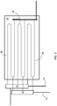
- FIG. 2 a multi-circuit evaporator 16 is shown.
- the evaporator 16 in Figure 2 comprises a plurality of evaporator coils 36.
- the main refrigeration circuit may include a refrigerant distributor 31 installed between the outlet of the expansion valve 18 adapted to distribute the refrigerant to the inlet of each of the plurality of coils 36 of the evaporator 16.
- the first injection line 21 may be directly connected to the distributor 31, as in Figure 2 , or the first injection line may 21 be directly connected to the line between the outlet of the expansion valve 18 and the inlet of the distributor 31.
- the second injection line 22 may be directly connected to a refrigerant distributor 32 which is adapted to distribute the heated refrigerant to an injection point of each of the plurality of coils 36, wherein the injection point is between the inlet and the outlet of each of the plurality of coils 36.
- the injection point may be halfway between the inlet and the outlet of each of the plurality of coils 36, or it may be closer to either the inlet or the outlet.
- a defrost mode of operation may be initiated automatically, for example if a certain time has lapsed since a previous defrost cycle was undertaken, or manually.
- the main refrigeration circuit is operated in a cooling mode to cool the air within the temperature-controlled environment (freezer cabinet).
- Valve 26 is open and valve 24 is closed, and fans 30 are turned on.
- Refrigerant circulates through the main refrigerant circuit in a normal refrigerant cycle, and the fans 30 draw air across the evaporator 16 and pass the cooled air into/through the temperature-controlled environment.
- Hot refrigeration fluid is diverted from the discharge line through the hot gas bypass line 20 and into first injection line 21 and second injection line 22.
- First injection line 21 delivers hot refrigeration fluid into distributor 31 which evenly distributes the refrigeration fluid between the inlets of each of the plurality of coils 36.
- Second injection line 22 delivers hot refrigeration fluid into distributor 32 which evenly distributes the refrigeration fluid between the injection points of each of the plurality of coils 36.
- the thermal energy of the refrigerant is more evenly distributed in the evaporator.
- the thermal energy is therefore more effectively used, and the defrost duration is shortened.
- the refrigeration system can therefore quickly resume normal operation.
- the overall energy consumption of the refrigeration system is also lowered.
- the refrigeration system may not include any elements other than those shown in Figure 1 , i.e. the main refrigeration circuit may be a typical single-stage vapor-compression refrigeration system.
- the refrigeration system may include other elements not shown in Figure 1 , such as a pressure regulator valve at the outlet of the evaporator 16 to modulate the pressure of the refrigerant before it reaches the intake of the compressor 12.
- the refrigeration system may also include other more complex additions to the main refrigeration circuit or hot gas bypass line 20 such as to adapt the refrigeration system for particular requirements.
Landscapes
- Engineering & Computer Science (AREA)
- Physics & Mathematics (AREA)
- Mechanical Engineering (AREA)
- Thermal Sciences (AREA)
- General Engineering & Computer Science (AREA)
- Defrosting Systems (AREA)
Priority Applications (1)
| Application Number | Priority Date | Filing Date | Title |
|---|---|---|---|
| EP20161245.4A EP3875873A1 (fr) | 2020-03-05 | 2020-03-05 | Système de réfrigération doté d'un dégivrage par gaz chauds |
Applications Claiming Priority (1)
| Application Number | Priority Date | Filing Date | Title |
|---|---|---|---|
| EP20161245.4A EP3875873A1 (fr) | 2020-03-05 | 2020-03-05 | Système de réfrigération doté d'un dégivrage par gaz chauds |
Publications (1)
| Publication Number | Publication Date |
|---|---|
| EP3875873A1 true EP3875873A1 (fr) | 2021-09-08 |
Family
ID=69779857
Family Applications (1)
| Application Number | Title | Priority Date | Filing Date |
|---|---|---|---|
| EP20161245.4A Withdrawn EP3875873A1 (fr) | 2020-03-05 | 2020-03-05 | Système de réfrigération doté d'un dégivrage par gaz chauds |
Country Status (1)
| Country | Link |
|---|---|
| EP (1) | EP3875873A1 (fr) |
Cited By (1)
| Publication number | Priority date | Publication date | Assignee | Title |
|---|---|---|---|---|
| CN115950075A (zh) * | 2022-12-22 | 2023-04-11 | 珠海格力电器股份有限公司 | 制冷设备的化霜控制方法和装置 |
Citations (5)
| Publication number | Priority date | Publication date | Assignee | Title |
|---|---|---|---|---|
| JPS52118260U (fr) * | 1976-03-05 | 1977-09-07 | ||
| JPS5579756U (fr) * | 1978-11-29 | 1980-06-02 | ||
| US4625524A (en) * | 1984-12-07 | 1986-12-02 | Hitachi, Ltd. | Air-cooled heat pump type refrigerating apparatus |
| CN107084561A (zh) * | 2017-06-19 | 2017-08-22 | Tcl空调器(中山)有限公司 | 空调器及其除霜控制方法 |
| KR102049426B1 (ko) * | 2019-06-25 | 2019-11-28 | (주)대성마리프 | 핫가스 인젝션 효과를 이용한 쿨러 및 그 쿨러를 포함한 착상방지 및 제상 시스템 |
-
2020
- 2020-03-05 EP EP20161245.4A patent/EP3875873A1/fr not_active Withdrawn
Patent Citations (5)
| Publication number | Priority date | Publication date | Assignee | Title |
|---|---|---|---|---|
| JPS52118260U (fr) * | 1976-03-05 | 1977-09-07 | ||
| JPS5579756U (fr) * | 1978-11-29 | 1980-06-02 | ||
| US4625524A (en) * | 1984-12-07 | 1986-12-02 | Hitachi, Ltd. | Air-cooled heat pump type refrigerating apparatus |
| CN107084561A (zh) * | 2017-06-19 | 2017-08-22 | Tcl空调器(中山)有限公司 | 空调器及其除霜控制方法 |
| KR102049426B1 (ko) * | 2019-06-25 | 2019-11-28 | (주)대성마리프 | 핫가스 인젝션 효과를 이용한 쿨러 및 그 쿨러를 포함한 착상방지 및 제상 시스템 |
Cited By (1)
| Publication number | Priority date | Publication date | Assignee | Title |
|---|---|---|---|---|
| CN115950075A (zh) * | 2022-12-22 | 2023-04-11 | 珠海格力电器股份有限公司 | 制冷设备的化霜控制方法和装置 |
Similar Documents
| Publication | Publication Date | Title |
|---|---|---|
| AU2008270655B2 (en) | Hot gas defrost method and apparatus | |
| CA2053297C (fr) | Systeme de refrigeration a degivrage par gaz chauds | |
| EP1967801B1 (fr) | Système de fourniture d'eau chaude | |
| US5056327A (en) | Hot gas defrost refrigeration system | |
| EP2397782B1 (fr) | Dispositif d'alimentation en eau chaude associé à une pompe à chaleur | |
| US6170270B1 (en) | Refrigeration system using liquid-to-liquid heat transfer for warm liquid defrost | |
| JP5595140B2 (ja) | ヒートポンプ式給湯・空調装置 | |
| CN101568773B (zh) | 包括至少两个隔热隔室的制冷设备 | |
| US5669222A (en) | Refrigeration passive defrost system | |
| US2713249A (en) | Liquid defrosting system and the like | |
| KR20060108222A (ko) | 넓은 온도 범위를 가진 공조용 히트 펌프 | |
| US20030037919A1 (en) | Connected chilling-heating system | |
| US20190032986A1 (en) | Refrigeration device comprising multiple storage chambers | |
| EP3859245B1 (fr) | Dispositif de pompe à chaleur | |
| EP3875873A1 (fr) | Système de réfrigération doté d'un dégivrage par gaz chauds | |
| US10443913B2 (en) | Refrigerator and method for controlling the same | |
| US4095438A (en) | Refrigeration system with hot gas defrost | |
| EP1781998B1 (fr) | Dispositif de refroidissement | |
| KR20090111663A (ko) | 냉장고 | |
| US20080016896A1 (en) | Refrigeration system with thermal conductive defrost | |
| JP2003139459A (ja) | 冷蔵庫 | |
| JPS61159072A (ja) | 冷凍装置 | |
| JP2024106862A (ja) | 冷水製造装置 | |
| CN118328601A (zh) | 空调装置、控制方法、装置及存储介质 | |
| JPS63207954A (ja) | 冷凍装置における能力制御装置 |
Legal Events
| Date | Code | Title | Description |
|---|---|---|---|
| PUAI | Public reference made under article 153(3) epc to a published international application that has entered the european phase |
Free format text: ORIGINAL CODE: 0009012 |
|
| STAA | Information on the status of an ep patent application or granted ep patent |
Free format text: STATUS: THE APPLICATION HAS BEEN PUBLISHED |
|
| AK | Designated contracting states |
Kind code of ref document: A1 Designated state(s): AL AT BE BG CH CY CZ DE DK EE ES FI FR GB GR HR HU IE IS IT LI LT LU LV MC MK MT NL NO PL PT RO RS SE SI SK SM TR |
|
| STAA | Information on the status of an ep patent application or granted ep patent |
Free format text: STATUS: REQUEST FOR EXAMINATION WAS MADE |
|
| 17P | Request for examination filed |
Effective date: 20220217 |
|
| RBV | Designated contracting states (corrected) |
Designated state(s): AL AT BE BG CH CY CZ DE DK EE ES FI FR GB GR HR HU IE IS IT LI LT LU LV MC MK MT NL NO PL PT RO RS SE SI SK SM TR |
|
| STAA | Information on the status of an ep patent application or granted ep patent |
Free format text: STATUS: EXAMINATION IS IN PROGRESS |
|
| 17Q | First examination report despatched |
Effective date: 20230210 |
|
| STAA | Information on the status of an ep patent application or granted ep patent |
Free format text: STATUS: THE APPLICATION HAS BEEN WITHDRAWN |
|
| 18W | Application withdrawn |
Effective date: 20230330 |