EP3875896A1 - Ultraschallsonde und verfahren zur messung der dicke eines zu prüfenden rohres damit - Google Patents
Ultraschallsonde und verfahren zur messung der dicke eines zu prüfenden rohres damit Download PDFInfo
- Publication number
- EP3875896A1 EP3875896A1 EP19877632.0A EP19877632A EP3875896A1 EP 3875896 A1 EP3875896 A1 EP 3875896A1 EP 19877632 A EP19877632 A EP 19877632A EP 3875896 A1 EP3875896 A1 EP 3875896A1
- Authority
- EP
- European Patent Office
- Prior art keywords
- pipe
- main body
- transducers
- ultrasonic probe
- inspected
- Prior art date
- Legal status (The legal status is an assumption and is not a legal conclusion. Google has not performed a legal analysis and makes no representation as to the accuracy of the status listed.)
- Granted
Links
Images




Classifications
-
- G—PHYSICS
- G01—MEASURING; TESTING
- G01B—MEASURING LENGTH, THICKNESS OR SIMILAR LINEAR DIMENSIONS; MEASURING ANGLES; MEASURING AREAS; MEASURING IRREGULARITIES OF SURFACES OR CONTOURS
- G01B17/00—Measuring arrangements characterised by the use of infrasonic, sonic or ultrasonic vibrations
- G01B17/02—Measuring arrangements characterised by the use of infrasonic, sonic or ultrasonic vibrations for measuring thickness
-
- G—PHYSICS
- G01—MEASURING; TESTING
- G01N—INVESTIGATING OR ANALYSING MATERIALS BY DETERMINING THEIR CHEMICAL OR PHYSICAL PROPERTIES
- G01N29/00—Investigating or analysing materials by the use of ultrasonic, sonic or infrasonic waves; Visualisation of the interior of objects by transmitting ultrasonic or sonic waves through the object
- G01N29/04—Analysing solids
- G01N29/041—Analysing solids on the surface of the material, e.g. using Lamb, Rayleigh or shear waves
-
- G—PHYSICS
- G01—MEASURING; TESTING
- G01N—INVESTIGATING OR ANALYSING MATERIALS BY DETERMINING THEIR CHEMICAL OR PHYSICAL PROPERTIES
- G01N2291/00—Indexing codes associated with group G01N29/00
- G01N2291/02—Indexing codes associated with the analysed material
- G01N2291/028—Material parameters
- G01N2291/02854—Length, thickness
-
- G—PHYSICS
- G01—MEASURING; TESTING
- G01N—INVESTIGATING OR ANALYSING MATERIALS BY DETERMINING THEIR CHEMICAL OR PHYSICAL PROPERTIES
- G01N2291/00—Indexing codes associated with group G01N29/00
- G01N2291/10—Number of transducers
- G01N2291/105—Number of transducers two or more emitters, two or more receivers
-
- G—PHYSICS
- G01—MEASURING; TESTING
- G01N—INVESTIGATING OR ANALYSING MATERIALS BY DETERMINING THEIR CHEMICAL OR PHYSICAL PROPERTIES
- G01N2291/00—Indexing codes associated with group G01N29/00
- G01N2291/26—Scanned objects
- G01N2291/263—Surfaces
- G01N2291/2636—Surfaces cylindrical from inside
-
- Y—GENERAL TAGGING OF NEW TECHNOLOGICAL DEVELOPMENTS; GENERAL TAGGING OF CROSS-SECTIONAL TECHNOLOGIES SPANNING OVER SEVERAL SECTIONS OF THE IPC; TECHNICAL SUBJECTS COVERED BY FORMER USPC CROSS-REFERENCE ART COLLECTIONS [XRACs] AND DIGESTS
- Y02—TECHNOLOGIES OR APPLICATIONS FOR MITIGATION OR ADAPTATION AGAINST CLIMATE CHANGE
- Y02E—REDUCTION OF GREENHOUSE GAS [GHG] EMISSIONS, RELATED TO ENERGY GENERATION, TRANSMISSION OR DISTRIBUTION
- Y02E30/00—Energy generation of nuclear origin
- Y02E30/30—Nuclear fission reactors
Definitions
- the present invention relates to an ultrasonic probe and method for measuring thickness of a pipe to be inspected with using the ultrasonic probe.
- a flaw inspection device for inspecting whether flaws, cracks, reduction of thickness or the like occurs in a pipe by an inspecting device inserted within the pipe through the opening provided on main pipes, and an inspection method using the device.
- General type of a flaw inspection device that includes an ultrasonic probe has been disclosed.
- Patent Publication 1 discloses a measuring device for measuring thickness of a pipe, from inside, to be used in a pipeline by means of an ultrasonic probe.
- the invention disclosed in Patent Publication 1 provide a thickness measuring device that can accurately measure the pipe thickness from inside of the pipe, even if the pipe is not filled with liquid.
- Ultrasonic probes are embedded in an annular seal cup of the device that is contact with the inner peripheral surface of the pipe.
- the annular seal cup formed of elastic material and pressed against the inner peripheral surface of the pipe is mounted on a moving body that moves along an axial direction inside the pipe. Further, by installing, at a plurality of positions of the seal cup, a plurality of ultrasonic probes each of which transmits ultrasonic wave toward the inner peripheral surfaces of the pipe, each of the ultrasonic probes is arranged to transmit ultrasonic wave and to receive the same reflected both at the inner surface and at the outer surface of the pipe.
- the thickness of the pipe can be thus calculated in accordance with the arrival times difference between the wave reflected at the inner peripheral surface of the pipe to be inspected and the wave reflected at the outer peripheral surface of the pipe.
- Patent Publication 2 discloses a tube wall thickness measuring device which is arranged to be inserted within a tube to be measured, and which is also movable along a coaxial direction of the tube.
- a tubular rotating body rotated by a water flow between two disc-shaped flanges having an outer diameter smaller than the inner diameter of the tube.
- an acoustic mirror that refracts ultrasonic wave having been emitted along the axial direction toward a tube radial direction.
- an ultrasonic wave probe for emitting the ultrasonic wave toward the acoustic mirror.
- the wall thickness measuring device With moving the wall thickness measuring device inside the tube to be measured, water is supplied into the rotating body from the rear flange, and the rotating body is rotated by the water flow ejected from the ejection port in the circumferential direction. Whereas, through the acoustic mirror, by refracting the ultrasonic waves emitted from the ultrasonic probe toward the axial direction of the tube, the ultrasonic waves spirally move along the coaxial direction. The tube wall thickness, within the whole length and around the whole circumference, thus can be measured.
- Patent Publication 3 relates to an ultrasonic probe used for flaw inspection of a pipe.
- a conventional ultrasonic probe including a transducer inserted in a pipe for emitting ultrasonic beam
- the emitted ultrasonic beam refracts when entering inside of a pipe to be inspected.
- Emitting surface of the transducer is flat, but the entering surface of the pipe to which the beam enters curves.
- Each of beam entering angles are different from each other due to positions of the transducer. Under these circumstances, since the entering beam scatters within the pipe, it is thus not possible to clearly detect the reflected beams.
- the transducers installed in the ultrasonic probe are arranged to have a concave curved surface opposing, from the coaxial direction of the pipe, to the inner surface of the pipe.
- Ultrasonic beams emitted from such formed transducers converge at a predetermined position within the pipe regardless of position of the ultrasonic probe, and the beam propagates within the pipe without scattering. As a result, the ultrasonic beam can propagate with being converged within the pipe.
- the materials to be transferred through the pipe is gas.
- an annular seal cup in which an ultrasonic probe has been mounted on circumference of the seal cup is thus arranged to be pressed against the inner peripheral surface of the pipe.
- the thickness measuring device of Patent Publication 1 calculate thickness of the pipe based on the difference of the arrival times between the wave reflected from the inner peripheral surface and one reflected from the outer peripheral surface.
- water since water is not used as a propagation medium, it is thus necessary to employ an arrangement in which a plurality of probes is mounted within a seal cup to be pressed against the inner peripheral surface of the pipe.
- Such ultrasonic probe can be used only for a pipe with specified diameter.
- the tube wall thickness measuring device disclosed in Patent Publication 2 is arranged to measure tube wall thickness with moving inside the tube by an ultrasonic probe from inside of the tube to be inspected.
- a tubular rotating body rotated by a water flow between two disc-shaped flanges having outer diameter smaller than the inner diameter of the tube.
- an acoustic mirror inclined in an oblique angle such as 45-dgrees, that refracts ultrasonic wave having been emitted along the axial direction into a tube radial direction.
- the ultrasonic probe provided on the front flange receives the ultrasonic waves emitted toward the acoustic mirror and measures the thickness of the tube.
- a string member For moving the ultrasonic probe, a string member is used.
- the ultrasonic wave having been emitted from the ultrasonic probe is reflected and refracted at the acoustic mirror provided in the tubular rotating body. Since the rotating mirror moves forward during such reflection and refraction, there is a gap among parts in the tube, which is to be inspected by the ultrasonic wave. Thus, there is a risk that inspection omission may occur depending on the moving speed of the device and the rotation speed of the mirror.
- the rotating body is arranged to rotate by the pressure of flowing water outputted from an opening on the rotating body, and there is also a risk that bubble may undesirably generates. Since the water for rotating the rotating body is supplied from a water supply tube, the whole construction of the device is complicated.
- the transducers installed in the ultrasonic probe are arranged to have a concaved curve surface opposing, from the coaxial direction of the pipe, to the inner surface of the pipe.
- Ultrasonic beams emitted from such formed transducers converge at a predetermined position within the pipe regardless of position of the ultrasonic probe.
- the shape of it is the curved surface, so as the ultrasonic beams emitted from the transducer converge at the predetermined position within the pipe regardless of the position of the probe ( Figs. 1 and 2 ). Accordingly, in Patent Publication 3, ultrasonic waves from the transducer do not perpendicularly enter the inner surface of the pipe.
- an ultrasonic probe which is movable within a pipe by water flow pressure for detecting abnormality of the pipe and for measuring thickness of the pipe.
- the ultrasonic probe is further arranged to transmit ultrasonic wave toward the inner surface of the pipe, and to receive the transmitted wave reflected at the inner surface as an echo signal.
- the present invention is thus characterized in that a plurality of transducers are mounted on circumference of a cylindrical main body, and that the transducers are so curved as to match the shape of the inner surface of the pipe.
- the ultrasonic waves having been emitted from the transducers are then perpendicularly radiated onto the surface of the pipe to be inspected.
- the waves are also perpendicularly reflected from the surface and detected as an echo signal to the transducers. Accordingly, as compared to a condition that the waves are emitted and received from the transducers inclined about the surface to be inspected, it is possible to suppress scattering or interference and to clearly obtain the data by selecting and using ultrasonic wave with wave lengths which corresponds to the thickness of pipe to be inspected.
- a plurality of transducers can be located on circumference of a cylindrical main body. These transducers can also be located, for example, continuously on the circumference of the main body. By employing such an arrangement, it becomes unnecessary to rotate the main body so that the transducers correctly oppose to the position on the surface which has not been opposed to the transducers for additionally emitting ultrasonic beam, which are necessary when using single or a few transducers.
- the ultrasonic probe according to the present invention can be also arranged to be supported by a buoyant main body, and by an optional guiding and buoyant unit which is buoyant and has resistance against water flow. Further, the ultrasonic probe further has sealing property against water. Thus, the probe easily floats and moves within the pipe, and easily inspect the pipe to be inspected.
- An ultrasonic probe according to the present invention is the ultrasonic probe movable within a pipe to be inspected for measuring thickness of the pipe from its inside, comprising:
- An ultrasonic probe according to the present invention may be the ultrasonic probe wherein the transducers are concentrically provided about the central axis of the main body.
- An ultrasonic probe according to the present invention may be the ultrasonic probe, wherein the transducers are arranged to perpendicularly emit ultrasonic wave toward an inner surface of the pipe, so that the wave perpendicularly reflected from the inner surface can be detected at the transducers.
- An ultrasonic probe according to the present invention may be the ultrasonic probe wherein the main body is cylindrical, and wherein the transducers, the surface of which is so curved, are provided at positions circularly designated around the main body, so that the transducers perpendicularly radiate ultrasonic wave onto the inner surface of the pipe and detect perpendicularly reflected waves.
- An ultrasonic probe according to the present invention can be used for a method for measuring thickness of a pipe to be inspected by a cylindrical ultrasonic probe, wherein the method can comprise the steps of:
- the ultrasonic probe according to the present invention is arranged to be movable within a pipe to be inspected by water flow, and to include a cylindrical main body which is coaxially provided with the pipe by a main body stably supporting unit.
- a plurality of transducers located along circumference of the main body are formed in a curved shape to match the shape of the inner surface of the pipe.
- the ultrasonic waves having been emitted from the transducers are then perpendicularly radiated onto the surface of the pipe to be inspected.
- the waves are also perpendicularly reflected and returned to the transducers from the surface as an echo signal. Accordingly, it is possible to clearly obtain the measured data without scattering or interference among the emitted and reflected ultrasonic waves.
- the ultrasonic probe of the present invention it is possible to replace the portion including the main body stably supporting unit with another one depending on the pipe diameter to be inspected. It is thus possible for the ultrasonic probe to inspect various types of pipes, respectively having its own diameter, by replacing parts of the device, which is significant effects.
- Fig. 1 shows a conventional ultrasonic probe inserted within a pipe to be inspected which has a cylindrical main body 30 and one or more plate-shaped transducer(s) 20 mounted on circumference of the main body.
- Fig. 2 shows an ultrasonic probe according to the present invention inserted within a pipe to be inspected which has a cylindrical main body 3 and one or more curved surface transducer(s) 2 mounted on circumference of the main body.
- the shape of the main body is not necessarily cylindrical; however, considering that a cross section of a boiler pipe to be inspected is usually circular, it is preferable to make the shape cylindrical.
- a guiding unit 5 is provided at the tip (the traveling direction) of the main body ( Fig. 3 ). Any shape of the guiding unit 5, which enable the ultrasonic probe to be easily inserted into the pipe, can be employed.
- the diameter of front part may be smaller than the pipe diameter, and a cross section of the front part may also be concentric with a cross section of the pipe perpendicular to the central axis.
- the central part of the front portion of the main body may be conically liked formed having a rounded tip portion (i.e., in a triangularly-shaped in a side view) with respect to the traveling direction of the main body.
- the main body including a conically tip front portion allow the ultrasonic probe to move within the pipe with reduced resistance against water flow.
- a main body stably supporting unit 4 as a buffering portion between the inner surface of the pipe and the main body.
- the main body stably supporting unit 4 surrounds the main body from the peripheral of the front portion toward backward direction with tilting in predetermined angle, and matches the central axes of the pipe to be inspected and the main body. In order to reduce resistance against the water flow, it is preferable to so form both the central portion at the front potion and the peripheral portion thereof of the main body as to smoothly link to the main body stably supporting unit 4.
- the main body stably supporting unit 4 for placing the main body 3 at the central portion within the pipe to be inspected is elastic and umbrella-shaped, at the side view, and is also formed, for example, in coarse mesh by metal.
- the main body stably supporting unit can match the central axis along the longitudinal direction of the main body with the central axis of the pipe. Accordingly, with using the transducers circularly mounted around the main body, it is possible to perpendicularly radiate ultrasonic beam emitted from the transducers onto the inner surface of the pipe. Furthermore, since the main body stably supporting unit is formed in coarse mesh state, the water flow passing through the mesh can also smoothly flow between the main body and the inner surface of the pipe. There is always water as a wave propagation medium between such circularly arranged transducers around the main body and the part to be inspected on the inner surface of the pipe.
- the main body stably supporting unit 4 is not necessarily an elastic and umbrella-shaped unit also with being formed in coarse mesh by metal which extends from the peripheral of the front portion toward backward direction with tilting in predetermined angle, on the condition that the unit 4 can stably place the main body 3 within the pipe. Both the shape and the material of the main body stably supporting unit 4 does not matter on the condition that the central axes of the pipe to be inspected and the main body are matched with each other, and that water flow is not prevented from smoothly flowing between the inner surface of the pipe and the main body.
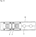
- rectangular members made of flexible materials can be placed on circumference of the main body in an evenly spaced manner ( Fig. 12 ).
- a metallic, elastic and coarse mesh-formed ring member (a rear side main body stably supporting unit 4b), which is analogous to the previously described main body stably supporting unit.
- Each of the guide portion at front portion of the main body and the main body stably supporting units 4a or 4b can be arranged to be connected to the main body including a plurality of transducers around the circumference thereof by for example, connecting screws or being detachable from the main body. Accordingly, even if the diameters of pipes to be inspected are different from each other, by replacing the main body stably supporting units 4a and 4b, the diameters of which match with the sizes of pipes to be used, the same main body and its transducers 2 mounted therein can be used without being changed.
- the shape of the transducers 2 has been formed with being so curved as to be matched with the shape of the inner surface of the pipe to be inspected. As a result, since the waves emitted from the transducers are about perpendicularly radiated onto the inner surface, the reflected waves also propagate perpendicularly, thus clear inspection results are obtainable.
- an ultrasonic wave transmitting unit can be packed in a water-proof buoyant linking unit 9 (distinct from the main body) that is connected to the main body by a flexible linking string.
- the position of the ultrasonic probe within the pipe can measure the subject by a wire that extends from the rear part thereof is within the scope of the present invention.
- the position of the ultrasonic probe may be measured by providing a plurality of evenly spaced buoyant and guide units for easily inserting the probe into the pipe, or by measuring the remaining length of the wire outside the pipe to be inspected ( Fig. 12 ).
- the shape, material or the like of the main body 3 of the ultrasonic probe of the present invention do not matter on the condition that the main body may be easily inserted into the pipe, and that wall thickness of the pipe may be measured by ultrasonic beam generated at the transducers 2 with being moved by water flow from the rear side of the pipe.
- the cross section of the pipe to be inspected is circular. It is then preferable to form the main body 3 cylindrically, and the diameter of the cross section of the main body is smaller than that of the pipe; however the shape of the cross section is not strictly limited to cylindrical.
- the diameter of the main body 3 is not particularly limited to the condition that the ultrasonic probe can move within the pipe by water flow. The main body 3 moves by water flow 13 from the rear side.
- the transducers 2 are located circularly around the main body.
- the main body have the certain size of the diameter. If the probe can easily pass through the bent portion of the pipe, and if, considering both the material of the pipe to be inspected and propagation velocity within water of the wave, the width of cross section of the main body with respect to the traveling direction thereof is substantially similar to the diameter of the pipe, the ultrasonic probe can effectively receive the pressure of the water flow thus easily moving within the pipe.
- the ultrasonic probe has its specific gravity substantially the same as that of water because the material and the weight thereof are required in such a manner that the probe may move without being prevented from moving by excessive buoyancy and gravity within water.
- the material and the weight are not necessarily limited as such, and the ultrasonic probe may have its material, volume and weight so that it moves smoothly by water flow.
- a pulse oscillator, a receiving unit, a power supplying unit, a controlling unit or the like of the transducer 2 of the ultrasonic probe may be provided within the probe itself (not shown). Whereas, these units may be contained within a buoyant and linking unit 9 (distinct from the main body) which is connected to the main body by a flexible linking string ( Figs. 9 and 10 ). In each of embodiments, these units are so water-proofed as to be protected from flood, and a power supplying cable 30 may be provided together with the flexible liking string linked to the main body 3.
- a spherical buoyant and guide unit 8 which is made by flexible soft rubber such as PVC is connected by flexible liking string.
- the buoyant and guide unit may have a plurality of buoyant elements evenly separated on a predetermined length wire.
- the ultrasonic probe of the present invention can be inserted into the pipe to be inspected with the wire, and the inserted position can be measured by the length of the wire outside of the pipe to be inspected.
- construction for attaching with the inner surface of the pipe and for matching the central axes of the pipe and the main body is band made by flexible resin fibers.
- the ultrasonic probe since the main body stably supporting unit itself may bend, the ultrasonic probe also may smoothly move within the pipe including bent portions ( Fig. 12 ).
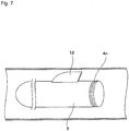
- the main body 3 also may have a one or more elastic side wing(s) 12 on a side wall thereof along the central axis in order to, when moving by water flow, make the positional relationship with the pipe stable, and to suppress undesirable rotation of the main body about the axis ( Fig. 7 ).
- the height of the side wing 12 is smaller than the length between the side surface of the main body and the inner surface of the pipe to be inspected, so that the side wing does not touch the inner surface when moving.
- the shape of the side wing does not matter on the condition that, in the case where fluid flow at the side of the main body, the main body is not undesirably rotated along the axis.
- the wing may be like a general vertical stabilizer of an aircraft.
- the shape of the main body 3 is formed, at the side view, in such a manner that the central portion of the rear side part is concaved toward the coaxially inside direction of a pipe to be inspected ( Fig. 6A ).
- a concaved shape may be further extending from the position at which both the concaved shape and the rear side wall of the main body 3 are crossed with each other (rear side cover 6).
- the ultrasonic probe of the present invention is provided a wire connected to outside of the pipe, so that the probe can be removed from the inside of the pipe by pulling the wire, if necessary.
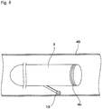
- roller member 10 contacting the inner surface of the pipe to be inspected, it becomes possible to appropriately recognize the position of the probe within the pipe.
- the roller member is provided on the side surface of the main body and arranged to contact the inner surface of the pipe by a spring member biasing the roller. As a result, with counting the number of rotations of the roller, it becomes possible to correctly grasp the position of the probe which has been inserted within the pipe in accordance with the number of rotations ( Fig. 8 ).
- the ultrasonic probe within the pipe measures the position of the pipe by a wire extending from the rear part of the main body is within the scope of the present invention ( Fig. 12 ).
Landscapes
- Physics & Mathematics (AREA)
- General Physics & Mathematics (AREA)
- Acoustics & Sound (AREA)
- Health & Medical Sciences (AREA)
- Life Sciences & Earth Sciences (AREA)
- Chemical & Material Sciences (AREA)
- Analytical Chemistry (AREA)
- Biochemistry (AREA)
- General Health & Medical Sciences (AREA)
- Immunology (AREA)
- Pathology (AREA)
- Investigating Or Analyzing Materials By The Use Of Ultrasonic Waves (AREA)
- Length Measuring Devices Characterised By Use Of Acoustic Means (AREA)
Applications Claiming Priority (2)
| Application Number | Priority Date | Filing Date | Title |
|---|---|---|---|
| JP2018206470A JP7216366B2 (ja) | 2018-11-01 | 2018-11-01 | 超音波探触子およびこれを用いた被検配管厚測定方法 |
| PCT/JP2019/042919 WO2020091011A1 (ja) | 2018-11-01 | 2019-10-31 | 超音波探触子およびこれを用いた被検配管厚測定方法 |
Publications (3)
| Publication Number | Publication Date |
|---|---|
| EP3875896A1 true EP3875896A1 (de) | 2021-09-08 |
| EP3875896A4 EP3875896A4 (de) | 2021-12-08 |
| EP3875896B1 EP3875896B1 (de) | 2025-06-11 |
Family
ID=70462395
Family Applications (1)
| Application Number | Title | Priority Date | Filing Date |
|---|---|---|---|
| EP19877632.0A Active EP3875896B1 (de) | 2018-11-01 | 2019-10-31 | Ultraschallsonde und verfahren zur messung der dicke eines zu prüfenden rohres damit |
Country Status (5)
| Country | Link |
|---|---|
| US (1) | US12158334B2 (de) |
| EP (1) | EP3875896B1 (de) |
| JP (1) | JP7216366B2 (de) |
| CN (1) | CN112997047B (de) |
| WO (1) | WO2020091011A1 (de) |
Families Citing this family (3)
| Publication number | Priority date | Publication date | Assignee | Title |
|---|---|---|---|---|
| US12196713B2 (en) | 2021-08-24 | 2025-01-14 | Saudi Arabian Oil Company | Convex ultrasonic sensor for weld inspection |
| WO2024197385A1 (en) * | 2023-03-31 | 2024-10-03 | Evident Canada, Inc. | Unsupervised thickness measurement for non-destructive testing |
| CN116626160B (zh) * | 2023-05-11 | 2026-03-31 | 醴陵华鑫电瓷科技股份有限公司 | 一种空心复合绝缘子的内部缺陷检测方法 |
Family Cites Families (29)
| Publication number | Priority date | Publication date | Assignee | Title |
|---|---|---|---|---|
| JPS6245167Y2 (de) * | 1981-02-20 | 1987-12-02 | ||
| US4391143A (en) * | 1981-05-29 | 1983-07-05 | The United States Of America As Represented By The United States Department Of Energy | Ultrasonic probe for inspecting double-wall tube |
| JPS59155709A (ja) * | 1983-02-25 | 1984-09-04 | Babcock Hitachi Kk | 超音波測定装置 |
| JPS59163562A (ja) * | 1983-03-09 | 1984-09-14 | Babcock Hitachi Kk | 超音波測定装置 |
| JPS6131962A (ja) * | 1984-07-25 | 1986-02-14 | Nippon Kogyo Kensa Kk | 配管の検査装置 |
| JPS61127600A (ja) * | 1984-11-27 | 1986-06-14 | 株式会社クボタ | 荷役車輛 |
| JPS6283608A (ja) * | 1985-10-09 | 1987-04-17 | Nippon Kokan Kk <Nkk> | 管の管厚測定装置 |
| JPS6333457U (de) * | 1986-08-21 | 1988-03-03 | ||
| US4955235A (en) * | 1987-07-30 | 1990-09-11 | Westinghouse Electric Corp. | Apparatus and method for providing a combined ultrasonic and eddy current inspection of a metallic body |
| JPH0333652A (ja) * | 1989-06-30 | 1991-02-13 | Hitachi Ltd | 超音波検査方法及び超音波検査装置 |
| JPH0451658U (de) | 1990-09-06 | 1992-04-30 | ||
| JP3104283B2 (ja) | 1991-04-15 | 2000-10-30 | 凸版印刷株式会社 | 超音波トランスジューサ及び超音波センサー並びにホール壁の膜厚測定方法及びその装置 |
| US5460046A (en) | 1994-05-25 | 1995-10-24 | Tdw Delaware, Inc. | Method and apparatus for ultrasonic pipeline inspection |
| JPH0953926A (ja) * | 1995-08-10 | 1997-02-25 | Ishikawajima Harima Heavy Ind Co Ltd | 管肉厚測定装置 |
| JPH11133006A (ja) * | 1997-10-31 | 1999-05-21 | Toshiba Corp | 超音波探傷装置とその方法 |
| JP2001027628A (ja) * | 1999-07-15 | 2001-01-30 | Nkk Corp | 多重配管の検査方法および装置 |
| JP2002090351A (ja) * | 2000-09-13 | 2002-03-27 | Osaka Gas Co Ltd | 管の超音波測定方法および装置 |
| JP2002090352A (ja) | 2000-09-13 | 2002-03-27 | Mitsubishi Heavy Ind Ltd | 軸方向欠陥検出用超音波探傷装置 |
| JP2002365033A (ja) * | 2001-06-04 | 2002-12-18 | Nippon Steel Corp | チューブの肉厚測定装置および方法 |
| US6904818B2 (en) * | 2002-04-05 | 2005-06-14 | Vetco Gray Inc. | Internal riser inspection device |
| US7293461B1 (en) * | 2003-10-22 | 2007-11-13 | Richard Girndt | Ultrasonic tubulars inspection device |
| JP5049095B2 (ja) * | 2007-10-30 | 2012-10-17 | 株式会社ディスコ | 研削ホイール |
| JP4524764B2 (ja) * | 2008-03-31 | 2010-08-18 | 住友金属工業株式会社 | 超音波探傷方法及び装置 |
| JP4768052B2 (ja) * | 2009-05-19 | 2011-09-07 | 成田空港給油施設株式会社 | 管厚測定装置 |
| JP5314550B2 (ja) * | 2009-09-30 | 2013-10-16 | 三菱重工業株式会社 | 管内挿入式超音波探傷検査装置及び超音波探傷検査システム |
| US8798940B2 (en) * | 2010-04-16 | 2014-08-05 | Olympus Ndt Inc. | Rotating array probe system for non-destructive testing |
| JP6129509B2 (ja) * | 2012-10-04 | 2017-05-17 | 東芝メディカルシステムズ株式会社 | 超音波医療装置及び超音波画像診断装置 |
| CN203298748U (zh) * | 2013-06-07 | 2013-11-20 | 南通友联数码技术开发有限公司 | 一种超声波管壁测厚装置 |
| CN103278114B (zh) * | 2013-06-07 | 2015-12-23 | 南通友联数码技术开发有限公司 | 一种超声波管壁测厚装置 |
-
2018
- 2018-11-01 JP JP2018206470A patent/JP7216366B2/ja active Active
-
2019
- 2019-10-31 WO PCT/JP2019/042919 patent/WO2020091011A1/ja not_active Ceased
- 2019-10-31 CN CN201980072067.7A patent/CN112997047B/zh active Active
- 2019-10-31 US US17/309,164 patent/US12158334B2/en active Active
- 2019-10-31 EP EP19877632.0A patent/EP3875896B1/de active Active
Also Published As
| Publication number | Publication date |
|---|---|
| EP3875896B1 (de) | 2025-06-11 |
| CN112997047A (zh) | 2021-06-18 |
| CN112997047B (zh) | 2023-09-05 |
| EP3875896A4 (de) | 2021-12-08 |
| JP2020071167A (ja) | 2020-05-07 |
| US12158334B2 (en) | 2024-12-03 |
| JP7216366B2 (ja) | 2023-02-01 |
| WO2020091011A1 (ja) | 2020-05-07 |
| US20220011099A1 (en) | 2022-01-13 |
Similar Documents
| Publication | Publication Date | Title |
|---|---|---|
| US10557831B2 (en) | Pipeline crack detection | |
| US12158334B2 (en) | Ultrasonic probe and method for measuring thickness of pipe being inspected using the same | |
| US6474165B1 (en) | Monitoring pipes | |
| CA2379108C (en) | Method and device for inspecting pipelines | |
| US7950284B2 (en) | Inspection device and method for inspection | |
| US20090095087A1 (en) | Ultrasonic probe, ultrasonic flaw detection method, and ultrasonic flaw detection apparatus | |
| US9404896B2 (en) | Two-dimensional TR probe array | |
| CN101839746A (zh) | 一种天然气管道积液测量方法和装置 | |
| US9207213B2 (en) | Method and apparatus for inspecting and monitoring pipe | |
| US8511424B2 (en) | Acoustic waveguide assemblies | |
| CN103728372A (zh) | 用于确定锅炉管道冷侧裂缝的方法以及实现该方法的物品 | |
| US10890471B2 (en) | Method and assembly for ultrasonic clamp-on flow measurement, and bodies for implementing off-center flow measurement | |
| US11874255B2 (en) | Dynamic adjustment of phased array parameters for ultrasonic inspection | |
| EP2416150B1 (de) | Ultraschallgerät zur erkennung von defekten an rohrenden | |
| US11162919B2 (en) | Ultrasonic based internal inspection of tubes | |
| WO2009001022A1 (en) | Profiling pig for detecting and quantifying internal corrosion in pipes | |
| Willems et al. | Qualification of a combined ultrasonic inspection tool for detection and sizing of circumferential weld cracks in offshore pipelines | |
| JP2009229451A (ja) | 管内挿入式超音波探傷検査装置 | |
| US11835485B2 (en) | Ultrasonic probe having flexible stabilizing element for probe alignment | |
| RU2312334C2 (ru) | Способ и устройство для контроля трубопроводов | |
| US20090120191A1 (en) | Methods and apparatus for inspecting furnace tubes | |
| MXPA03006531A (es) | Procedimiento y dispositivo para la inspeccion de tuberia. |
Legal Events
| Date | Code | Title | Description |
|---|---|---|---|
| STAA | Information on the status of an ep patent application or granted ep patent |
Free format text: STATUS: THE INTERNATIONAL PUBLICATION HAS BEEN MADE |
|
| PUAI | Public reference made under article 153(3) epc to a published international application that has entered the european phase |
Free format text: ORIGINAL CODE: 0009012 |
|
| STAA | Information on the status of an ep patent application or granted ep patent |
Free format text: STATUS: REQUEST FOR EXAMINATION WAS MADE |
|
| 17P | Request for examination filed |
Effective date: 20210520 |
|
| AK | Designated contracting states |
Kind code of ref document: A1 Designated state(s): AL AT BE BG CH CY CZ DE DK EE ES FI FR GB GR HR HU IE IS IT LI LT LU LV MC MK MT NL NO PL PT RO RS SE SI SK SM TR |
|
| A4 | Supplementary search report drawn up and despatched |
Effective date: 20211105 |
|
| RIC1 | Information provided on ipc code assigned before grant |
Ipc: G01B 17/02 20060101AFI20211029BHEP |
|
| DAV | Request for validation of the european patent (deleted) | ||
| DAX | Request for extension of the european patent (deleted) | ||
| STAA | Information on the status of an ep patent application or granted ep patent |
Free format text: STATUS: EXAMINATION IS IN PROGRESS |
|
| 17Q | First examination report despatched |
Effective date: 20231123 |
|
| GRAP | Despatch of communication of intention to grant a patent |
Free format text: ORIGINAL CODE: EPIDOSNIGR1 |
|
| STAA | Information on the status of an ep patent application or granted ep patent |
Free format text: STATUS: GRANT OF PATENT IS INTENDED |
|
| INTG | Intention to grant announced |
Effective date: 20250206 |
|
| GRAS | Grant fee paid |
Free format text: ORIGINAL CODE: EPIDOSNIGR3 |
|
| GRAA | (expected) grant |
Free format text: ORIGINAL CODE: 0009210 |
|
| STAA | Information on the status of an ep patent application or granted ep patent |
Free format text: STATUS: THE PATENT HAS BEEN GRANTED |
|
| RAP3 | Party data changed (applicant data changed or rights of an application transferred) |
Owner name: EBARA ENVIRONMENTAL PLANT CO., LTD. Owner name: HIBOT CORPORATION |
|
| P01 | Opt-out of the competence of the unified patent court (upc) registered |
Free format text: CASE NUMBER: APP_20160/2025 Effective date: 20250428 |
|
| AK | Designated contracting states |
Kind code of ref document: B1 Designated state(s): AL AT BE BG CH CY CZ DE DK EE ES FI FR GB GR HR HU IE IS IT LI LT LU LV MC MK MT NL NO PL PT RO RS SE SI SK SM TR |
|
| REG | Reference to a national code |
Ref country code: GB Ref legal event code: FG4D |
|
| REG | Reference to a national code |
Ref country code: CH Ref legal event code: EP |
|
| REG | Reference to a national code |
Ref country code: DE Ref legal event code: R096 Ref document number: 602019071123 Country of ref document: DE |
|
| REG | Reference to a national code |
Ref country code: IE Ref legal event code: FG4D |
|
| PG25 | Lapsed in a contracting state [announced via postgrant information from national office to epo] |
Ref country code: FI Free format text: LAPSE BECAUSE OF FAILURE TO SUBMIT A TRANSLATION OF THE DESCRIPTION OR TO PAY THE FEE WITHIN THE PRESCRIBED TIME-LIMIT Effective date: 20250611 Ref country code: ES Free format text: LAPSE BECAUSE OF FAILURE TO SUBMIT A TRANSLATION OF THE DESCRIPTION OR TO PAY THE FEE WITHIN THE PRESCRIBED TIME-LIMIT Effective date: 20250611 |
|
| REG | Reference to a national code |
Ref country code: LT Ref legal event code: MG9D |
|
| PG25 | Lapsed in a contracting state [announced via postgrant information from national office to epo] |
Ref country code: NO Free format text: LAPSE BECAUSE OF FAILURE TO SUBMIT A TRANSLATION OF THE DESCRIPTION OR TO PAY THE FEE WITHIN THE PRESCRIBED TIME-LIMIT Effective date: 20250911 Ref country code: GR Free format text: LAPSE BECAUSE OF FAILURE TO SUBMIT A TRANSLATION OF THE DESCRIPTION OR TO PAY THE FEE WITHIN THE PRESCRIBED TIME-LIMIT Effective date: 20250912 |
|
| REG | Reference to a national code |
Ref country code: NL Ref legal event code: MP Effective date: 20250611 |
|
| PG25 | Lapsed in a contracting state [announced via postgrant information from national office to epo] |
Ref country code: BG Free format text: LAPSE BECAUSE OF FAILURE TO SUBMIT A TRANSLATION OF THE DESCRIPTION OR TO PAY THE FEE WITHIN THE PRESCRIBED TIME-LIMIT Effective date: 20250611 |
|
| PG25 | Lapsed in a contracting state [announced via postgrant information from national office to epo] |
Ref country code: HR Free format text: LAPSE BECAUSE OF FAILURE TO SUBMIT A TRANSLATION OF THE DESCRIPTION OR TO PAY THE FEE WITHIN THE PRESCRIBED TIME-LIMIT Effective date: 20250611 |
|
| PG25 | Lapsed in a contracting state [announced via postgrant information from national office to epo] |
Ref country code: RS Free format text: LAPSE BECAUSE OF FAILURE TO SUBMIT A TRANSLATION OF THE DESCRIPTION OR TO PAY THE FEE WITHIN THE PRESCRIBED TIME-LIMIT Effective date: 20250911 |
|
| PG25 | Lapsed in a contracting state [announced via postgrant information from national office to epo] |
Ref country code: LV Free format text: LAPSE BECAUSE OF FAILURE TO SUBMIT A TRANSLATION OF THE DESCRIPTION OR TO PAY THE FEE WITHIN THE PRESCRIBED TIME-LIMIT Effective date: 20250611 |
|
| PG25 | Lapsed in a contracting state [announced via postgrant information from national office to epo] |
Ref country code: NL Free format text: LAPSE BECAUSE OF FAILURE TO SUBMIT A TRANSLATION OF THE DESCRIPTION OR TO PAY THE FEE WITHIN THE PRESCRIBED TIME-LIMIT Effective date: 20250611 |
|
| PG25 | Lapsed in a contracting state [announced via postgrant information from national office to epo] |
Ref country code: PT Free format text: LAPSE BECAUSE OF FAILURE TO SUBMIT A TRANSLATION OF THE DESCRIPTION OR TO PAY THE FEE WITHIN THE PRESCRIBED TIME-LIMIT Effective date: 20251013 |
|
| REG | Reference to a national code |
Ref country code: AT Ref legal event code: MK05 Ref document number: 1802570 Country of ref document: AT Kind code of ref document: T Effective date: 20250611 |
|
| PG25 | Lapsed in a contracting state [announced via postgrant information from national office to epo] |
Ref country code: IS Free format text: LAPSE BECAUSE OF FAILURE TO SUBMIT A TRANSLATION OF THE DESCRIPTION OR TO PAY THE FEE WITHIN THE PRESCRIBED TIME-LIMIT Effective date: 20251011 |
|
| PGFP | Annual fee paid to national office [announced via postgrant information from national office to epo] |
Ref country code: DE Payment date: 20251028 Year of fee payment: 7 |
|
| PGFP | Annual fee paid to national office [announced via postgrant information from national office to epo] |
Ref country code: GB Payment date: 20251120 Year of fee payment: 7 |
|
| PG25 | Lapsed in a contracting state [announced via postgrant information from national office to epo] |
Ref country code: AT Free format text: LAPSE BECAUSE OF FAILURE TO SUBMIT A TRANSLATION OF THE DESCRIPTION OR TO PAY THE FEE WITHIN THE PRESCRIBED TIME-LIMIT Effective date: 20250611 Ref country code: SM Free format text: LAPSE BECAUSE OF FAILURE TO SUBMIT A TRANSLATION OF THE DESCRIPTION OR TO PAY THE FEE WITHIN THE PRESCRIBED TIME-LIMIT Effective date: 20250611 |
|
| PGFP | Annual fee paid to national office [announced via postgrant information from national office to epo] |
Ref country code: FR Payment date: 20251024 Year of fee payment: 7 |
|
| PG25 | Lapsed in a contracting state [announced via postgrant information from national office to epo] |
Ref country code: CZ Free format text: LAPSE BECAUSE OF FAILURE TO SUBMIT A TRANSLATION OF THE DESCRIPTION OR TO PAY THE FEE WITHIN THE PRESCRIBED TIME-LIMIT Effective date: 20250611 |
|
| PG25 | Lapsed in a contracting state [announced via postgrant information from national office to epo] |
Ref country code: PL Free format text: LAPSE BECAUSE OF FAILURE TO SUBMIT A TRANSLATION OF THE DESCRIPTION OR TO PAY THE FEE WITHIN THE PRESCRIBED TIME-LIMIT Effective date: 20250611 |
|
| PG25 | Lapsed in a contracting state [announced via postgrant information from national office to epo] |
Ref country code: EE Free format text: LAPSE BECAUSE OF FAILURE TO SUBMIT A TRANSLATION OF THE DESCRIPTION OR TO PAY THE FEE WITHIN THE PRESCRIBED TIME-LIMIT Effective date: 20250611 |
|
| PG25 | Lapsed in a contracting state [announced via postgrant information from national office to epo] |
Ref country code: RO Free format text: LAPSE BECAUSE OF FAILURE TO SUBMIT A TRANSLATION OF THE DESCRIPTION OR TO PAY THE FEE WITHIN THE PRESCRIBED TIME-LIMIT Effective date: 20250611 Ref country code: SK Free format text: LAPSE BECAUSE OF FAILURE TO SUBMIT A TRANSLATION OF THE DESCRIPTION OR TO PAY THE FEE WITHIN THE PRESCRIBED TIME-LIMIT Effective date: 20250611 |
|
| REG | Reference to a national code |
Ref country code: DE Ref legal event code: R097 Ref document number: 602019071123 Country of ref document: DE |
|
| PG25 | Lapsed in a contracting state [announced via postgrant information from national office to epo] |
Ref country code: DK Free format text: LAPSE BECAUSE OF FAILURE TO SUBMIT A TRANSLATION OF THE DESCRIPTION OR TO PAY THE FEE WITHIN THE PRESCRIBED TIME-LIMIT Effective date: 20250611 |
|
| PG25 | Lapsed in a contracting state [announced via postgrant information from national office to epo] |
Ref country code: IT Free format text: LAPSE BECAUSE OF FAILURE TO SUBMIT A TRANSLATION OF THE DESCRIPTION OR TO PAY THE FEE WITHIN THE PRESCRIBED TIME-LIMIT Effective date: 20250611 |
|
| PLBE | No opposition filed within time limit |
Free format text: ORIGINAL CODE: 0009261 |
|
| STAA | Information on the status of an ep patent application or granted ep patent |
Free format text: STATUS: NO OPPOSITION FILED WITHIN TIME LIMIT |
|
| REG | Reference to a national code |
Ref country code: CH Ref legal event code: L10 Free format text: ST27 STATUS EVENT CODE: U-0-0-L10-L00 (AS PROVIDED BY THE NATIONAL OFFICE) Effective date: 20260423 |