EP3875990A1 - Système d'inspection d'un dépôt - Google Patents
Système d'inspection d'un dépôt Download PDFInfo
- Publication number
- EP3875990A1 EP3875990A1 EP21159835.4A EP21159835A EP3875990A1 EP 3875990 A1 EP3875990 A1 EP 3875990A1 EP 21159835 A EP21159835 A EP 21159835A EP 3875990 A1 EP3875990 A1 EP 3875990A1
- Authority
- EP
- European Patent Office
- Prior art keywords
- data
- industrial truck
- warehouse
- laser scanner
- computing unit
- Prior art date
- Legal status (The legal status is an assumption and is not a legal conclusion. Google has not performed a legal analysis and makes no representation as to the accuracy of the status listed.)
- Granted
Links
Images




Classifications
-
- B—PERFORMING OPERATIONS; TRANSPORTING
- B65—CONVEYING; PACKING; STORING; HANDLING THIN OR FILAMENTARY MATERIAL
- B65G—TRANSPORT OR STORAGE DEVICES, e.g. CONVEYORS FOR LOADING OR TIPPING, SHOP CONVEYOR SYSTEMS OR PNEUMATIC TUBE CONVEYORS
- B65G1/00—Storing articles, individually or in orderly arrangement, in warehouses or magazines
- B65G1/02—Storage devices
- B65G1/04—Storage devices mechanical
-
- B—PERFORMING OPERATIONS; TRANSPORTING
- B66—HOISTING; LIFTING; HAULING
- B66F—HOISTING, LIFTING, HAULING OR PUSHING, NOT OTHERWISE PROVIDED FOR, e.g. DEVICES WHICH APPLY A LIFTING OR PUSHING FORCE DIRECTLY TO THE SURFACE OF A LOAD
- B66F9/00—Devices for lifting or lowering bulky or heavy goods for loading or unloading purposes
- B66F9/06—Devices for lifting or lowering bulky or heavy goods for loading or unloading purposes movable, with their loads, on wheels or the like, e.g. fork-lift trucks
- B66F9/063—Automatically guided
-
- G—PHYSICS
- G01—MEASURING; TESTING
- G01S—RADIO DIRECTION-FINDING; RADIO NAVIGATION; DETERMINING DISTANCE OR VELOCITY BY USE OF RADIO WAVES; LOCATING OR PRESENCE-DETECTING BY USE OF THE REFLECTION OR RERADIATION OF RADIO WAVES; ANALOGOUS ARRANGEMENTS USING OTHER WAVES
- G01S17/00—Systems using the reflection or reradiation of electromagnetic waves other than radio waves, e.g. lidar systems
- G01S17/88—Lidar systems specially adapted for specific applications
- G01S17/93—Lidar systems specially adapted for specific applications for anti-collision purposes
- G01S17/931—Lidar systems specially adapted for specific applications for anti-collision purposes of land vehicles
-
- B—PERFORMING OPERATIONS; TRANSPORTING
- B65—CONVEYING; PACKING; STORING; HANDLING THIN OR FILAMENTARY MATERIAL
- B65G—TRANSPORT OR STORAGE DEVICES, e.g. CONVEYORS FOR LOADING OR TIPPING, SHOP CONVEYOR SYSTEMS OR PNEUMATIC TUBE CONVEYORS
- B65G1/00—Storing articles, individually or in orderly arrangement, in warehouses or magazines
- B65G1/02—Storage devices
- B65G1/04—Storage devices mechanical
- B65G1/137—Storage devices mechanical with arrangements or automatic control means for selecting which articles are to be removed
-
- B—PERFORMING OPERATIONS; TRANSPORTING
- B66—HOISTING; LIFTING; HAULING
- B66F—HOISTING, LIFTING, HAULING OR PUSHING, NOT OTHERWISE PROVIDED FOR, e.g. DEVICES WHICH APPLY A LIFTING OR PUSHING FORCE DIRECTLY TO THE SURFACE OF A LOAD
- B66F9/00—Devices for lifting or lowering bulky or heavy goods for loading or unloading purposes
- B66F9/06—Devices for lifting or lowering bulky or heavy goods for loading or unloading purposes movable, with their loads, on wheels or the like, e.g. fork-lift trucks
- B66F9/075—Constructional features or details
- B66F9/07504—Accessories, e.g. for towing, charging, locking
-
- B—PERFORMING OPERATIONS; TRANSPORTING
- B66—HOISTING; LIFTING; HAULING
- B66F—HOISTING, LIFTING, HAULING OR PUSHING, NOT OTHERWISE PROVIDED FOR, e.g. DEVICES WHICH APPLY A LIFTING OR PUSHING FORCE DIRECTLY TO THE SURFACE OF A LOAD
- B66F9/00—Devices for lifting or lowering bulky or heavy goods for loading or unloading purposes
- B66F9/06—Devices for lifting or lowering bulky or heavy goods for loading or unloading purposes movable, with their loads, on wheels or the like, e.g. fork-lift trucks
- B66F9/075—Constructional features or details
- B66F9/0755—Position control; Position detectors
-
- B—PERFORMING OPERATIONS; TRANSPORTING
- B66—HOISTING; LIFTING; HAULING
- B66F—HOISTING, LIFTING, HAULING OR PUSHING, NOT OTHERWISE PROVIDED FOR, e.g. DEVICES WHICH APPLY A LIFTING OR PUSHING FORCE DIRECTLY TO THE SURFACE OF A LOAD
- B66F9/00—Devices for lifting or lowering bulky or heavy goods for loading or unloading purposes
- B66F9/06—Devices for lifting or lowering bulky or heavy goods for loading or unloading purposes movable, with their loads, on wheels or the like, e.g. fork-lift trucks
- B66F9/075—Constructional features or details
- B66F9/12—Platforms; Forks; Other load supporting or gripping members
- B66F9/127—Working platforms
-
- B—PERFORMING OPERATIONS; TRANSPORTING
- B66—HOISTING; LIFTING; HAULING
- B66F—HOISTING, LIFTING, HAULING OR PUSHING, NOT OTHERWISE PROVIDED FOR, e.g. DEVICES WHICH APPLY A LIFTING OR PUSHING FORCE DIRECTLY TO THE SURFACE OF A LOAD
- B66F9/00—Devices for lifting or lowering bulky or heavy goods for loading or unloading purposes
- B66F9/06—Devices for lifting or lowering bulky or heavy goods for loading or unloading purposes movable, with their loads, on wheels or the like, e.g. fork-lift trucks
- B66F9/075—Constructional features or details
- B66F9/12—Platforms; Forks; Other load supporting or gripping members
- B66F9/14—Platforms; Forks; Other load supporting or gripping members laterally movable, e.g. swingable, for slewing or transverse movements
- B66F9/147—Whole unit including fork support moves relative to mast
- B66F9/149—Whole unit including fork support rotates
-
- G—PHYSICS
- G01—MEASURING; TESTING
- G01B—MEASURING LENGTH, THICKNESS OR SIMILAR LINEAR DIMENSIONS; MEASURING ANGLES; MEASURING AREAS; MEASURING IRREGULARITIES OF SURFACES OR CONTOURS
- G01B11/00—Measuring arrangements characterised by the use of optical techniques
- G01B11/002—Measuring arrangements characterised by the use of optical techniques for measuring two or more coordinates
-
- G—PHYSICS
- G01—MEASURING; TESTING
- G01S—RADIO DIRECTION-FINDING; RADIO NAVIGATION; DETERMINING DISTANCE OR VELOCITY BY USE OF RADIO WAVES; LOCATING OR PRESENCE-DETECTING BY USE OF THE REFLECTION OR RERADIATION OF RADIO WAVES; ANALOGOUS ARRANGEMENTS USING OTHER WAVES
- G01S17/00—Systems using the reflection or reradiation of electromagnetic waves other than radio waves, e.g. lidar systems
- G01S17/02—Systems using the reflection of electromagnetic waves other than radio waves
- G01S17/06—Systems determining position data of a target
- G01S17/42—Simultaneous measurement of distance and other co-ordinates
-
- G—PHYSICS
- G01—MEASURING; TESTING
- G01S—RADIO DIRECTION-FINDING; RADIO NAVIGATION; DETERMINING DISTANCE OR VELOCITY BY USE OF RADIO WAVES; LOCATING OR PRESENCE-DETECTING BY USE OF THE REFLECTION OR RERADIATION OF RADIO WAVES; ANALOGOUS ARRANGEMENTS USING OTHER WAVES
- G01S17/00—Systems using the reflection or reradiation of electromagnetic waves other than radio waves, e.g. lidar systems
- G01S17/88—Lidar systems specially adapted for specific applications
-
- G—PHYSICS
- G01—MEASURING; TESTING
- G01S—RADIO DIRECTION-FINDING; RADIO NAVIGATION; DETERMINING DISTANCE OR VELOCITY BY USE OF RADIO WAVES; LOCATING OR PRESENCE-DETECTING BY USE OF THE REFLECTION OR RERADIATION OF RADIO WAVES; ANALOGOUS ARRANGEMENTS USING OTHER WAVES
- G01S17/00—Systems using the reflection or reradiation of electromagnetic waves other than radio waves, e.g. lidar systems
- G01S17/88—Lidar systems specially adapted for specific applications
- G01S17/89—Lidar systems specially adapted for specific applications for mapping or imaging
-
- G—PHYSICS
- G05—CONTROLLING; REGULATING
- G05D—SYSTEMS FOR CONTROLLING OR REGULATING NON-ELECTRIC VARIABLES
- G05D1/00—Control of position, course, altitude or attitude of land, water, air or space vehicles, e.g. using automatic pilots
- G05D1/02—Control of position or course in two dimensions
- G05D1/021—Control of position or course in two dimensions specially adapted to land vehicles
- G05D1/0212—Control of position or course in two dimensions specially adapted to land vehicles with means for defining a desired trajectory
- G05D1/0225—Control of position or course in two dimensions specially adapted to land vehicles with means for defining a desired trajectory involving docking at a fixed facility, e.g. base station or loading bay
-
- G—PHYSICS
- G05—CONTROLLING; REGULATING
- G05D—SYSTEMS FOR CONTROLLING OR REGULATING NON-ELECTRIC VARIABLES
- G05D1/00—Control of position, course, altitude or attitude of land, water, air or space vehicles, e.g. using automatic pilots
- G05D1/02—Control of position or course in two dimensions
- G05D1/021—Control of position or course in two dimensions specially adapted to land vehicles
- G05D1/0231—Control of position or course in two dimensions specially adapted to land vehicles using optical position detecting means
- G05D1/0238—Control of position or course in two dimensions specially adapted to land vehicles using optical position detecting means using obstacle or wall sensors
- G05D1/024—Control of position or course in two dimensions specially adapted to land vehicles using optical position detecting means using obstacle or wall sensors in combination with a laser
-
- G—PHYSICS
- G05—CONTROLLING; REGULATING
- G05D—SYSTEMS FOR CONTROLLING OR REGULATING NON-ELECTRIC VARIABLES
- G05D1/00—Control of position, course, altitude or attitude of land, water, air or space vehicles, e.g. using automatic pilots
- G05D1/20—Control system inputs
- G05D1/24—Arrangements for determining position or orientation
- G05D1/247—Arrangements for determining position or orientation using signals provided by artificial sources external to the vehicle, e.g. navigation beacons
-
- G—PHYSICS
- G05—CONTROLLING; REGULATING
- G05D—SYSTEMS FOR CONTROLLING OR REGULATING NON-ELECTRIC VARIABLES
- G05D1/00—Control of position, course, altitude or attitude of land, water, air or space vehicles, e.g. using automatic pilots
- G05D1/60—Intended control result
- G05D1/656—Interaction with payloads or external entities
- G05D1/661—Docking at a base station
-
- G—PHYSICS
- G06—COMPUTING OR CALCULATING; COUNTING
- G06Q—INFORMATION AND COMMUNICATION TECHNOLOGY [ICT] SPECIALLY ADAPTED FOR ADMINISTRATIVE, COMMERCIAL, FINANCIAL, MANAGERIAL OR SUPERVISORY PURPOSES; SYSTEMS OR METHODS SPECIALLY ADAPTED FOR ADMINISTRATIVE, COMMERCIAL, FINANCIAL, MANAGERIAL OR SUPERVISORY PURPOSES, NOT OTHERWISE PROVIDED FOR
- G06Q10/00—Administration; Management
- G06Q10/08—Logistics, e.g. warehousing, loading or distribution; Inventory or stock management
-
- G—PHYSICS
- G06—COMPUTING OR CALCULATING; COUNTING
- G06Q—INFORMATION AND COMMUNICATION TECHNOLOGY [ICT] SPECIALLY ADAPTED FOR ADMINISTRATIVE, COMMERCIAL, FINANCIAL, MANAGERIAL OR SUPERVISORY PURPOSES; SYSTEMS OR METHODS SPECIALLY ADAPTED FOR ADMINISTRATIVE, COMMERCIAL, FINANCIAL, MANAGERIAL OR SUPERVISORY PURPOSES, NOT OTHERWISE PROVIDED FOR
- G06Q10/00—Administration; Management
- G06Q10/08—Logistics, e.g. warehousing, loading or distribution; Inventory or stock management
- G06Q10/087—Inventory or stock management, e.g. order filling, procurement or balancing against orders
Definitions
- the present invention relates to a system for inspecting a warehouse, an industrial truck comprising such a system and a method for inspecting a warehouse with such a system.
- a shelf inspection is usually carried out by a competent person, whereby the competent person usually compares the status of the individual shelves (occupied, unoccupied), the contour of the individual stored goods and barcodes of the goods with the corresponding data of a warehouse management system (WMS) and If necessary, positioning errors of the goods on the shelf (crooked, inclined, too far left or right), deformations of the goods due to, for example, a yielding film winding as well as shelf damage (kink in a carrier, carrier angle inclined) detected.
- WMS warehouse management system
- the checked storage condition is documented, with If the above-mentioned irregularities or damage are detected, appropriate measures are taken to restore a proper storage condition.
- a manual check as described above involves high personnel costs, especially for high-bay warehouses, which can contain shelves with a height of more than 40 meters, while on the other hand automatic systems may not be operated for the checking period for security reasons.
- a method for the automated inspection of storage facilities with a special probe which has the form of a storage aid used in the warehouse, such as a pallet, and optical and visual sensors for determining the distance from itself to the supporting structure of the storage facility and for measuring parameters of the environment.
- the probe For the check, the probe must be moved by means of a means of transporting stored goods, such as a forklift, and, if necessary, inserted into individual storage compartments.
- a storage goods transport means or a storage compartment is occupied for the check, which cannot be used for normal logistics orders during the check time.
- a method for providing the position of storage locations in a warehouse with an industrial truck which has a location system and at least one lateral 3D camera, the direction of view of which is oriented transversely to a main direction of travel.
- image data of storage locations and the shelf structure can be recorded in a field of view of the camera on one side of the industrial truck.
- a 3D camera based on time of flight measurement usually only has a restricted field of view with an angle of approximately 60 °. To get shelves on either side of the To capture the truck at the same time, there must therefore be at least two 3D cameras, each of which is to be attached to one side of the truck.
- the object is achieved by a system for inspecting a warehouse, comprising: a laser scanner which can be fastened to an industrial truck and is set up for it, a Carry out a scanning process in a plane essentially perpendicular to the main direction of travel of the industrial truck in order to scan the surroundings of a warehouse on at least one side, preferably both sides of the industrial truck and to generate scan data based thereon, a computing unit which is set up to receive the scan data, and To obtain data on the absolute position and / or the relative change in position of the industrial truck, or data from which one or more of these variables can be derived, the computing unit also being set up on the basis of the scanning data and the data on the absolute position and / or to construct the relative change in position of the industrial truck three-dimensional data of the environment.
- Laser scanners are electro-optical sensors that scan their surroundings using a rapidly rotating laser measuring beam, the measurement being based on the so-called time-of-flight (ToF) method.
- a commercially available laser scanner is usually set up to scan the surroundings in one plane, with a pulsed laser beam being deflected in different directions in the plane with the aid of a rotating mirror.
- a laser scanner has a significantly larger scanning angle, whereby scanning can take place in a sector of up to 270 ° with a commercially available laser scanner.
- the laser scanner can be attached to the industrial truck in such a way that its scanning plane is essentially perpendicular to the main direction of travel of the industrial truck.
- the surroundings can thus be scanned on at least one side, preferably both sides, of the industrial truck during the measurement run.
- the laser scanner scans with a predetermined scanning frequency.
- a laser pulse is continuously emitted after a certain angular step, thus triggering an individual measurement.
- the data of the Individual measurements are forwarded to the computing unit, the computing unit being set up to construct three-dimensional data of the environment, namely a so-called point cloud as a total of the individual measurements.
- the computing unit is therefore also set up to receive data on the absolute position and / or the relative change in position of the industrial truck, or data from which one or more of these variables can be derived.
- the relative change in position of the industrial truck can not only be used to determine the absolute spatial position of the industrial truck, but can also be used to determine the direction of movement of the industrial truck.
- the absolute position and / or the relative change in position of the industrial truck can be detected directly by existing or additional sensor systems for localizing the industrial truck, such as optical sensors, RFID sensors or other sensors for localization or tracking purposes.
- the computing unit can receive data from which the computing unit can derive the absolute position and / or the relative change in position of the industrial truck.
- data can include odometry data of the industrial truck, for example, which are explained in more detail below.
- the vertical resolution of the point cloud is determined by the angular resolution of the laser scanner and the distance between the laser scanner and an object surface to be scanned, such as a shelf front, with the horizontal resolution being determined by the travel speed of the industrial truck and the scanning frequency of the laser scanner.
- the laser scanner In contrast to a movable probe, the laser scanner must be attached to the industrial truck in such a way that it does not have to be carried separately for a check by the truck with its load-carrying device can also take place during periods of low workload.
- the personnel expenditure can be significantly reduced with the invention.
- early detection of damage and irregularities in the warehouse is possible, since the check with the system according to the invention can also be carried out during the processing of transport orders and thus much more frequently.
- storage or retrieval processes can be supported on the basis of the generated three-dimensional data of a storage location or compartment, positioning errors or deviations can be recognized in good time and, if necessary, corrected so that the accuracy of the storage or retrieval processes can be increased. This not only improves the work safety of an automated warehouse, but also reduces the required safety distance between two adjacent stored auxiliary cargo in an automated warehouse, so that existing warehouses can also be automated without costly conversions.
- the computing unit is set up to receive odometry data of the industrial truck, the data on the absolute position and / or the relative change in position of the industrial truck being derived from the odometry data of the industrial truck.
- Odometry data of a vehicle contain position and orientation data of the vehicle, which are determined by means of its propulsion system.
- a yaw rate sensor in, for example, an anti-lock braking system (ABS) or a vehicle dynamics controller (ESP) and a steering sensor for a steering wheel angle measurement are used, with the measured variables from the wheel speed sensor for vehicles on a track can also be sufficient on their own.
- ABS anti-lock braking system
- ESP vehicle dynamics controller
- the laser scanner has scanning directions which contain the two horizontal directions and the vertical direction upwards.
- the laser scanner thus has a scanning angle of at least 180 °, so that racking devices on both sides of the industrial truck can be detected simultaneously with one measurement run.
- the laser scanner is therefore preferably set up in such a way that the scanning area can also include the surroundings above the laser scanner.
- the laser scanner is preferably set up to scan the floor of the shelf facilities on both sides. This means that the entire front of a shelf can be recorded with one measurement run.
- the computing unit is also set up to detect individual bearing elements from the constructed three-dimensional data of the environment.
- Storage elements in the context of this invention relate to all possible logistics elements or units that are used or required either for transport orders or for the storage of goods in a warehouse. This includes stored goods such as goods or loading units from bundled goods or packages, storage aids such as pallets or containers, storage locations or compartments, shelves or shelf elements such as vertical beams or horizontal beams, etc.
- the computing unit is preferably set up to recognize various bearing elements from a constructed point cloud by means of image processing and to determine three-dimensional data of the individually recognized bearing elements based thereon.
- the image processing can either be done by segmenting the point cloud and then comparing the individual segmented parts with predefined patterns or rules, or it can be based on a method with artificial intelligence with learning ability, whereby the processing unit can be continuously trained with data in order to adapt to new environments to be able to customize.
- the computing unit is preferably also set up to receive data from a warehouse management system.
- a warehouse management system is a software-based system that manages the control of warehouse processes.
- various data can be stored in a warehouse management system, which can be queried from external systems if necessary. These include data relating to order management, logistics process management, such as the management of storage, retrieval or relocation processes, inventory management, master data management, etc.
- the data in the warehouse management system can be used for various purposes.
- the computing unit can also determine the spatial position of the laser scanner based on the data of a relocation order, or the constructed data of the Compare the environment with the inventory data stored in the warehouse management system in order to check the inventory of a warehouse.
- identification numbers of the individual storage elements can be stored in the warehouse management system, so that information relating to the recorded storage elements can be combined with other identification sensors such as barcode or RFID readers that are attached to the industrial truck , can be called up by the warehouse management system and compared with the constructed data of the warehouse elements.
- the computing unit is also set up to check a storage condition on the basis of a comparison of the three-dimensional data of the individually detected storage elements with corresponding data from the warehouse management system. For example, as mentioned above, the number of detected stored goods or the number of storage spaces still available can be compared with the corresponding numbers stored in the warehouse management system.
- the computing unit can also compare positions, dimensions of the identified bearing elements and / or a distance between two adjacent bearing elements with the corresponding master data from the warehouse management system.
- the computing unit is preferably also set up to check a bearing condition on the basis of a comparison of the three-dimensional data of the individual detected bearing elements with predefined reference data.
- the reference data can be, for example, the specific regulation data defined according to standards, such as the permitted deflection of a shelf support, the permitted distance between two adjacent pallets stored in a high-bay warehouse, or the permitted dimensions of a load, etc. be stored either as master data in the warehouse management system or locally in a memory of the processing unit. It is also possible to store the data in another external memory or in a cloud.
- the computing unit can, if necessary, detect irregularities in the bearing and / or damage to the individual bearing elements.
- the computing unit is preferably also set up to document the storage condition and / or to output instructions based on the storage condition.
- the computing unit can preferably generate an electronic file with details of the warehouse check.
- the processing unit can output an instruction in order to initiate manual or automatic restoration of the bearing condition. For example, an automatic relocation of a load can be initiated with an automated industrial truck if the computing unit has recognized that a pallet has been stored in the wrong storage compartment.
- the invention relates to an industrial truck comprising a system according to the invention.
- the system according to the first aspect of the invention preferably serves as an extension of the industrial truck, the advantages of the industrial truck resulting from the advantages of the system.
- the industrial truck is a track-guided industrial truck.
- automated storage systems are increasingly used, with an automated industrial truck being the heart of an automated storage system, which is set up to drive along a predefined lane without manual intervention or with significantly reduced manual intervention and logistics processes, such as storage, retrieval or a Relocation to be carried out automatically.
- the use of the system according to the first aspect of the invention is particularly advantageous for a track-guided industrial truck, since a warehouse inspection can thereby be carried out completely automatically.
- the security of an associated automated warehouse is increased by the fact that the accuracy of the automated logistics processes can be increased through the constructed three-dimensional data of the environment. Since the lane is already predefined, the odometry data of the industrial truck can be determined solely on the basis of the measurement data from wheel speed sensors.
- the industrial truck comprises a lifting frame, the laser scanner being permanently attached to an attachment part of the industrial truck which is connected to the lifting frame in a movable manner, directly or indirectly, the height of the laser scanner in relation to the ground is adjustable with a work function of the truck.
- the lifting frame is the core of a forklift truck, which is set up to perform a work function such as lifting or lowering a load, the lifting frame being assigned a plurality of attachments which can be moved up and down on the lifting frame with a work function.
- the work function can also include a mast tilt function, by means of which the entire lifting frame can be tilted by an angle defined by the work function.
- the industrial truck is preferably a high-bay forklift which includes a driver's position with a protective roof and / or a load-carrying device that can be moved back and forth laterally transversely to the straight-ahead driving direction of the forklift, the laser scanner preferably being permanently attached to the protective roof or to the load-carrying device.
- the high-bay stacker is preferably set up to store a load on a shelf in a narrow aisle between shelves of a high-bay warehouse or to remove it from a shelf and preferably comprises a multi-part telescopically extendable mast, to which the driver's position with the overhead guard and / or the swiveling load-carrying device is assigned, with a driver's seat does not necessarily have to be present in an automated high-bay forklift.
- the relative position of the laser scanner in relation to the body of the high-bay stacker can thus be adjusted with a work function of the high-bay stacker.
- both the overhead guard and the load-carrying device have points at which the laser scanner can see both the left and the right shelf level and the work function is not impaired.
- the sequence control of the narrow-aisle high-bay stacker can be optimized, so that there are several advantages:
- the required safety distance between two adjacent stored auxiliary loads in a high-bay warehouse that is served by an automated high-bay stacker can go from currently 100 mm to 75 mm be reduced.
- existing warehouses can also be automated and optimized without complex conversions.
- a positioning error for example due to uneven floors or deviations in the shelf structure, can be compensated for while a transport order is being carried out. It is no longer necessary to teach in all the shelves beforehand, which can greatly reduce the set-up effort for a high-bay warehouse.
- irregularities or damage to a high-bay warehouse are recognized at an early stage, so that work safety and logistics efficiency can be increased.
- the present invention relates to a method for inspecting a warehouse by means of a system according to the invention, the system optionally being assigned to an industrial truck according to the invention, comprising: scanning the surroundings and generating the scanning data; Acquisition of data about the absolute position and / or the relative change in position of the industrial truck, or data from which one or more of these variables can be derived; Construction of three-dimensional data of the environment based on the scan data and odometry data of the industrial truck.
- the advantages of the method correspond to the advantages of the system according to the first aspect of the invention.
- the method further comprises: acquisition of odometry data of the industrial truck, wherein the data about the absolute position and / or the relative change in position of the industrial truck are to be derived from the odometry data of the industrial truck.
- the method further comprises an automatic activation of the system when a reference point is recognized.
- the system for inspecting a narrow-aisle high-bay warehouse that is assigned to a high-bay stacker can be used when the high-bay stacker enters
- a narrow aisle of the high-bay warehouse can be activated automatically if a reader attached to the high-bay stacker has detected a reference point at the entrance area of the narrow aisle, the reference point being identified, for example, by a barcode attached to one side of the shelf or an RFID transponder embedded in the floor.
- the system can be switched off again in the same way.
- the method preferably further comprises detecting the current spatial position of the laser scanner, for example on the basis of externally input data and / or on reference points captured by the laser scanner, the method further constructing three-dimensional data of the environment based on the spatial position of the laser scanner.
- the laser scanner is permanently attached to the industrial truck, the relative position of the laser scanner in relation to the body of the industrial truck can be changed by means of a work function of the industrial truck, the work function being a lifting of a load to a certain height and a lowering of a load a certain height, a tilting of the mast of the industrial truck with a certain angle of inclination, a sideshift function of the load handling equipment of the industrial truck and / or a pivoting of the load handling equipment of the industrial truck.
- the externally entered data include, for example, data from a warehouse management system that precisely defines the work function.
- the external environment can also influence the spatial position of the laser scanner, for example in the form of uneven floors, which can be detected using existing or additional sensors.
- reference points such as a barcode, an RFID transponder or an image marker, can also be set up in the environment, which include or represent certain spatial information, the reference points either can be detected by the laser scanner or by other sensors and can also help determine the spatial position of the laser scanner.
- the method further comprises detecting individual bearing elements from the constructed three-dimensional data of the environment.
- the method further comprises receiving data from a warehouse management system.
- the method preferably further comprises checking a warehouse condition on the basis of a comparison of the three-dimensional data of the individually detected warehouse elements with corresponding data from the warehouse management system.
- the method further comprises checking a bearing condition on the basis of a comparison of the three-dimensional data of the individually detected bearing elements with predefined reference data.
- the method preferably further comprises a detection of damage and irregularities in the bearing condition.
- the method further comprises outputting instructions on the basis of the storage condition and, if necessary, restoring a proper storage condition, with the restoration of the storage condition being able to take place either automatically or manually.
- Figure 1 shows a side view of an embodiment of an industrial truck 1 with a system for inspecting a warehouse according to the invention, wherein in this embodiment the industrial truck is a high-bay stacker designed as a three-sided stacker.
- the industrial truck 1 is equipped with wheels 2 which are attached to wheel suspensions (not shown) and which stand on the driving surface 4.
- the wheel suspensions are in turn attached to a vehicle body 6, to which a lifting frame 8, which is also attached in an upright position, is attached.
- the lifting frame 8 is designed to be telescopically extendable in several parts, as shown in FIG Figure 1 can be seen from the extended position shown with dashed lines.
- a support structure 9 is attached as a driver's seat carrier so that it can be moved vertically.
- the support structure 9 has a cantilever assembly 24 protruding forward from the mast 8 in the main direction of travel G of the industrial truck as a boom, which supports a platform 11 of a driver's position 12 on its underside and which supports it on its underside protruding end a side push frame 34 carries.
- the driver's seat 12 is designed as a liftable driver's cab, the frame of which with the driver's seat platform 11 as the cab floor has a rear wall, side walls and a protective roof 22 for the driver.
- the side push frame 34 is attached to the cantilever beam arrangement 24.
- the side pusher frame 34 is part of a known load-carrying assembly 36, which also has a side-pusher 38 in the form of a swivel-type pusher 38 with an additional lifting frame 40 arranged at the front, on which a load-carrying fork 42 is arranged as a load-carrying element and can be displaced laterally transversely to the straight-ahead driving direction G on the side pusher frame 34 is vertically movable with a fork carriage assembly.
- the additional frame 40 is, together with the load carrying fork 42, about the vertical axis 44 between the in Figure 1
- the position shown with the lateral alignment of the load carrying fork 42 or its load carrying tines 43 (transverse alignment to the left in relation to the straight-ahead driving direction G) and a position with the opposite lateral alignment (transverse alignment right) of the load carrying tines 43 can be pivoted.
- All of the work functions assigned to the mast 8 and the load-bearing assembly 36 can be operated by means of a hydraulic device (not shown).
- the industrial truck 1 comprises a system for inspecting a high-bay warehouse, the system comprising a laser scanner 52 and a computing unit 60, which are shown in FIG Figure 1 is not shown.
- the system preferably serves as an extension of the industrial truck, with the computing unit 60 either being assigned to an existing on-board computer of the industrial truck 1 or being provided by a separately designed computer system.
- the laser scanner 52 is preferably attached to an attachment on the industrial truck, the is movably connected directly or indirectly to the mast 8, the height of the laser scanner 52 in relation to the driving surface 4 being adjustable with a work function of the industrial truck 1.
- the laser scanner 52 is preferably fixedly attached to the top of the sideshift device 38. Alternative locations such as the overhead guard 22 are also suitable for attaching the laser scanner 52.
- the laser scanner 52 is set up to carry out a scanning process in a plane E essentially perpendicular to the main direction of travel of the industrial truck G.
- Figure 2 shows the scanning plane E of the laser scanner in a view in the direction of the main direction of travel G of the industrial truck.
- the laser scanner 52 preferably has a continuous scanning area 54 of more than 180 ° and is currently positioned at a certain height h in relation to the underbody 4 in such a way that scanning directions of the laser scanner 52 are the two horizontal directions H1 and H2 and the vertical direction upwards V1 include.
- the fronts of the shelves 80 and 82 on both sides of the industrial truck 1 can be detected with a single measurement run.
- the scanning beam of the laser scanner 52 can reach shelf fronts from the shelf to the top floors of the shelves 80 and 82, so that all storage locations on both sides of the lane can be detected at once.
- the system can therefore be particularly advantageous and time-saving, for example to carry out an inventory of a warehouse or to check an occupancy status of the storage locations.
- FIG 3 shows roughly schematically the structure of the system 50 for inspecting a warehouse in the industrial truck 1 from Figure 1 is used.
- the system 50 comprises the laser scanner 52 and the computing unit 60, the laser scanner 52 being set up to scan the environment in order to generate scan data, and the computing unit 60 being set up to receive the scan data and to construct three-dimensional data of the environment based thereon . Since the scan plane E is perpendicular to the In the main direction of travel of the industrial truck G, additional data about the spatial position or the direction of movement of the laser scanner 52 are required in order to construct three-dimensional data of the surroundings.
- the computing unit 60 is set up to receive odometry data of the industrial truck 70, the odometry data of the industrial truck 70 including position and orientation data of the vehicle, which can preferably be determined by means of its propulsion system.
- the direction of movement of the laser scanner 52 results from the direction of travel of the industrial truck 1 and thus directly from the odometry data of the industrial truck 70 Odometry data 70, other data may also be relevant and used.
- the height of the laser scanner h in relation to the driving surface 4 can have a work function, for example lifting or lowering a Load carrying element of the industrial truck 1 are set.
- the horizontal position of the laser scanner can also be changed by means of a work function, for example pivoting a load-bearing element.
- the relative position of the laser scanner 52 in relation to the body 6 of the industrial truck 1 changes preferably to be consulted when determining the spatial position of the laser scanner 52.
- Further data 74 for example with regard to environmental influences such as uneven floors or reference data for the localization of the industrial truck can also be relevant for determining the spatial position of the laser scanner, such further data 70 being able to be obtained with various already existing or separately constructed sensor-based solutions.
- the computing unit 60 constructs three-dimensional data of the environment in the form of a point cloud.
- the computing unit 60 can recognize various bearing elements from the constructed point cloud and, based on this, determine three-dimensional data of the individually recognized bearing elements.
- the computing unit 60 is able to automatically detect damage or irregularities in a warehouse. In Figure 4 and in Figure 5 an example of this is illustrated in each case.
- Figure 4 shows part of a shelf 84 which comprises a plurality of horizontal beams 86 and vertical beams 88. It's over Figure 4 it can be seen that shelf damage in the form of a deformed horizontal beam 86 has occurred.
- the arithmetic unit 60 can recognize from the constructed point cloud and corresponding image processing algorithms that the horizontal beam 86 is deformed. On the basis of this, the computing unit 60 can output an instruction to initiate a repair or replacement of the horizontal support 86.
- Figure 5 also shows part of a shelf 84 with horizontal beams and vertical beams. It's over Figure 5 It can be seen that two stored loading units 90 and 92 are deformed in such a way that the loading unit 94 is pressed together by the other two and has thereby also been deformed. If the loading unit 94 were to be removed from storage with an automated industrial truck without taking this irregularity into account, the adjacent loading units 90 and 92 could, in the worst case, fall off the shelf due to a resulting frictional force and cause an accident.
- this irregularity can be detected before the loading unit 94 is removed from storage in order to avoid a possible accident.
- the computing unit 60 can detect that the distance between the loading units 90 and 94 and the distance between the loading units 92 and 94 are each below a predefined permitted reference value, which is, for example, the Warehouse management system is stored.
- the processing unit 60 will issue a corresponding instruction so that the loading unit 94 will not be removed from storage until this irregularity has been rectified.
- FIG. 11 schematically shows a strategy of a storage process in combination with the exemplary embodiment from FIG Figure 1 .
- the industrial truck 1 preferably receives a transport order from a warehouse management system, which specifies the destination storage location at which a load is to be stored. Based on this, a navigation system of the industrial truck guides the industrial truck 1 to a target position, the load carrying fork 42 of the industrial truck possibly also being set to a target position by a control system of the industrial truck so that the load can be stored at the target storage location.
- the system for inspecting the warehouse 50 is preferably activated and the speed of the industrial truck is reduced if necessary so that the destination storage area can be scanned in direction G when the industrial truck drives past the destination storage area and three-dimensional data of the destination storage area can be constructed based on this can be.
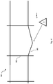
- the scan area 100 is marked by dashed lines, wherein in Figure 6 the complete destination storage area with the associated storage carriers and neighboring goods is scanned.
- the computing unit 60 of the system can determine the target target position P target to be approached by the load carrying fork 42 for storage, the position P target corresponding to a center point in the width direction of the target storage location in the embodiment shown.
- the predetermined actual target position is preferably replaced by the target target position P target .
- the updated actual target position of the storage location can then be approached and storage can thus be carried out.
- the control system of the industrial truck can calculate the target target position P target together with data on the dimensions of the target storage compartment, which are stored locally or externally (such as in the warehouse management system, for example).
- the in Fig. 7 The strategy presented here has the disadvantage that part of the target storage area cannot be scanned, but this disadvantage can be compensated for, for example, by using additional sensors, such as a camera, which monitor the storage area and / or the surroundings in the vicinity of the storage area Storage process also recorded.
Landscapes
- Engineering & Computer Science (AREA)
- Physics & Mathematics (AREA)
- General Physics & Mathematics (AREA)
- Transportation (AREA)
- Structural Engineering (AREA)
- Radar, Positioning & Navigation (AREA)
- Remote Sensing (AREA)
- Mechanical Engineering (AREA)
- Business, Economics & Management (AREA)
- Electromagnetism (AREA)
- Civil Engineering (AREA)
- Geology (AREA)
- Life Sciences & Earth Sciences (AREA)
- Automation & Control Theory (AREA)
- Aviation & Aerospace Engineering (AREA)
- Economics (AREA)
- Computer Networks & Wireless Communication (AREA)
- Human Resources & Organizations (AREA)
- Operations Research (AREA)
- Development Economics (AREA)
- Theoretical Computer Science (AREA)
- Entrepreneurship & Innovation (AREA)
- General Business, Economics & Management (AREA)
- Marketing (AREA)
- Tourism & Hospitality (AREA)
- Quality & Reliability (AREA)
- Strategic Management (AREA)
- Optics & Photonics (AREA)
- Finance (AREA)
- Accounting & Taxation (AREA)
- Warehouses Or Storage Devices (AREA)
Applications Claiming Priority (1)
| Application Number | Priority Date | Filing Date | Title |
|---|---|---|---|
| DE102020105804.7A DE102020105804A1 (de) | 2020-03-04 | 2020-03-04 | System zur Inspektion eines Lagers |
Publications (3)
| Publication Number | Publication Date |
|---|---|
| EP3875990A1 true EP3875990A1 (fr) | 2021-09-08 |
| EP3875990B1 EP3875990B1 (fr) | 2023-08-16 |
| EP3875990B8 EP3875990B8 (fr) | 2023-09-27 |
Family
ID=74844763
Family Applications (1)
| Application Number | Title | Priority Date | Filing Date |
|---|---|---|---|
| EP21159835.4A Active EP3875990B8 (fr) | 2020-03-04 | 2021-03-01 | Système d'inspection d'un dépôt |
Country Status (4)
| Country | Link |
|---|---|
| US (1) | US11970378B2 (fr) |
| EP (1) | EP3875990B8 (fr) |
| CN (1) | CN113353518A (fr) |
| DE (1) | DE102020105804A1 (fr) |
Cited By (1)
| Publication number | Priority date | Publication date | Assignee | Title |
|---|---|---|---|---|
| EP4140935A1 (fr) * | 2021-04-22 | 2023-03-01 | STILL GmbH | Procédé de commande d'un chariot de manutention autonome |
Families Citing this family (19)
| Publication number | Priority date | Publication date | Assignee | Title |
|---|---|---|---|---|
| FI128300B (en) * | 2018-09-03 | 2020-03-13 | Rocla Oyj | Truck control |
| GB2611625B (en) * | 2021-10-05 | 2024-08-07 | Wrs Solutions Ltd | Goods monitoring system and method of use thereof |
| GB2620859B (en) * | 2021-10-05 | 2024-07-03 | Wrs Solutions Ltd | Goods monitoring system and method of use thereof |
| GB2611818B (en) * | 2021-10-18 | 2024-12-04 | Three Smith Group Ltd | Damage detection system |
| JP7597693B2 (ja) * | 2021-11-05 | 2024-12-10 | トヨタ自動車株式会社 | 搬送システム |
| IT202200023853A1 (it) * | 2022-11-18 | 2024-05-18 | Toyota Mat Handling Manufacturing Italy S P A | Carrello industriale avente un controllo migliorato delle operazioni di carico e scarico |
| IT202200026451A1 (it) * | 2022-12-22 | 2024-06-22 | Toyota Mat Handling Manufacturing Italy S P A | Riconoscimento anomalie di carico |
| IT202300006033A1 (it) * | 2023-03-29 | 2024-09-29 | Toyota Mat Handling Manufacturing Italy S P A | Magazzino di merci con una funzione di monitoraggio |
| JP7693264B2 (ja) | 2023-03-29 | 2025-06-17 | 三菱ロジスネクスト株式会社 | 搬送車、連結部、距離特定方法および距離特定プログラム |
| IT202300006054A1 (it) * | 2023-03-29 | 2024-09-29 | Toyota Mat Handling Manufacturing Italy S P A | Carrello industriale con controllo migliorato |
| US20250005510A1 (en) * | 2023-06-30 | 2025-01-02 | A-1 Packaging Solutions, Inc. | Disposing RFID Tags in Concrete Surface |
| DE102023120569A1 (de) | 2023-08-03 | 2025-02-06 | Audi Hungaria Zrt | Inventursystem sowie Inventurverfahren zur Prüfung eines Warenbestands in einem Warenlager |
| JP2025029431A (ja) * | 2023-08-21 | 2025-03-06 | 東芝テック株式会社 | 情報処理装置、情報処理システム、及びプログラム |
| GB2633397B (en) * | 2023-09-09 | 2026-03-11 | Combilift | Load scanning |
| US20250131803A1 (en) * | 2023-10-21 | 2025-04-24 | Isura Ranatunga | Intelligent Alert System for Warehouse Environments and Related Methods |
| DE102024115850A1 (de) * | 2024-06-06 | 2025-12-11 | SSI Schäfer AG | Automatische Regalinspektion in Hochregallagern |
| DE102024121642A1 (de) * | 2024-07-30 | 2026-02-05 | Linde Material Handling Gmbh | Gabelstapler, insbesondere autonomer oder automatisierter Gabelstapler |
| DE102024131005A1 (de) * | 2024-10-24 | 2026-04-30 | Still Gesellschaft Mit Beschränkter Haftung | Ticketing-System für ein intralogistisches Umfeld mit Flurförderzeugen |
| CN120191875B (zh) * | 2025-05-24 | 2025-08-01 | 苏州海豚之星智能科技有限公司 | 一种托盘叉取方法、系统、存储介质及程序产品 |
Citations (5)
| Publication number | Priority date | Publication date | Assignee | Title |
|---|---|---|---|---|
| DE102011051204B3 (de) | 2011-06-20 | 2012-10-25 | Dematic Gmbh | Verfahren und Vorrichtung zur Inspektion von Lagereinrichtungen |
| US8655588B2 (en) * | 2011-05-26 | 2014-02-18 | Crown Equipment Limited | Method and apparatus for providing accurate localization for an industrial vehicle |
| DE102016122485A1 (de) | 2016-11-22 | 2018-05-24 | Jungheinrich Aktiengesellschaft | Verfahren zur Bereitstellung der Positionen von Lagerplätzen in einem Lager und Flurförderzeug |
| US20180155169A1 (en) | 2015-05-12 | 2018-06-07 | Kabushiki Kaisha Toyota Jidoshokki | Forklift |
| WO2019141929A1 (fr) * | 2018-01-16 | 2019-07-25 | Balyo | Procédé et dispositif de cartographie pour véhicule automatique |
Family Cites Families (7)
| Publication number | Priority date | Publication date | Assignee | Title |
|---|---|---|---|---|
| JPH11193111A (ja) * | 1997-12-26 | 1999-07-21 | Murata Mach Ltd | 物品格納装置 |
| AU2012201565B2 (en) * | 2011-03-18 | 2015-11-12 | The Raymond Corporation | Mast and integral display mount for a material handling vehicle |
| US20130054129A1 (en) * | 2011-08-26 | 2013-02-28 | INRO Technologies Limited | Method and apparatus for using unique landmarks to locate industrial vehicles at start-up |
| US10762468B2 (en) * | 2016-09-22 | 2020-09-01 | Amazon Technologies, Inc. | Adaptive process for guiding human-performed inventory tasks |
| DE102016220810A1 (de) * | 2016-10-24 | 2018-04-26 | Jungheinrich Aktiengesellschaft | Proaktives Verringern von Schwingungen in einem Flurförderzeug |
| EP3823916B1 (fr) * | 2018-07-20 | 2022-08-24 | TGW Logistics Group GmbH | Procédé et entrepôt destiné à entreposer et à préparer des marchandises |
| US11209832B2 (en) * | 2019-08-18 | 2021-12-28 | Cobalt Robotics Inc. | Elevator interactions by mobile robot |
-
2020
- 2020-03-04 DE DE102020105804.7A patent/DE102020105804A1/de not_active Withdrawn
-
2021
- 2021-03-01 EP EP21159835.4A patent/EP3875990B8/fr active Active
- 2021-03-03 US US17/190,568 patent/US11970378B2/en active Active
- 2021-03-04 CN CN202110238486.2A patent/CN113353518A/zh active Pending
Patent Citations (5)
| Publication number | Priority date | Publication date | Assignee | Title |
|---|---|---|---|---|
| US8655588B2 (en) * | 2011-05-26 | 2014-02-18 | Crown Equipment Limited | Method and apparatus for providing accurate localization for an industrial vehicle |
| DE102011051204B3 (de) | 2011-06-20 | 2012-10-25 | Dematic Gmbh | Verfahren und Vorrichtung zur Inspektion von Lagereinrichtungen |
| US20180155169A1 (en) | 2015-05-12 | 2018-06-07 | Kabushiki Kaisha Toyota Jidoshokki | Forklift |
| DE102016122485A1 (de) | 2016-11-22 | 2018-05-24 | Jungheinrich Aktiengesellschaft | Verfahren zur Bereitstellung der Positionen von Lagerplätzen in einem Lager und Flurförderzeug |
| WO2019141929A1 (fr) * | 2018-01-16 | 2019-07-25 | Balyo | Procédé et dispositif de cartographie pour véhicule automatique |
Non-Patent Citations (1)
| Title |
|---|
| DANIEL HUBER ET AL: "Using laser scanners for modeling and analysis in architecture, engineering, and construction", INFORMATION SCIENCES AND SYSTEMS (CISS), 2010 44TH ANNUAL CONFERENCE ON, IEEE, PISCATAWAY, NJ, USA, 17 March 2010 (2010-03-17), pages 1 - 6, XP031676435, ISBN: 978-1-4244-7416-5 * |
Cited By (1)
| Publication number | Priority date | Publication date | Assignee | Title |
|---|---|---|---|---|
| EP4140935A1 (fr) * | 2021-04-22 | 2023-03-01 | STILL GmbH | Procédé de commande d'un chariot de manutention autonome |
Also Published As
| Publication number | Publication date |
|---|---|
| US20210276842A1 (en) | 2021-09-09 |
| US11970378B2 (en) | 2024-04-30 |
| CN113353518A (zh) | 2021-09-07 |
| EP3875990B1 (fr) | 2023-08-16 |
| EP3875990B8 (fr) | 2023-09-27 |
| DE102020105804A1 (de) | 2021-09-09 |
Similar Documents
| Publication | Publication Date | Title |
|---|---|---|
| EP3875990B1 (fr) | Système d'inspection d'un dépôt | |
| EP2468678B1 (fr) | Chariot de manutention équipé d'un capteur pour détecter l'environnement spatial et procédé de fonctionnement d'un tel chariot de manutention | |
| EP3323770B1 (fr) | Procédé de fourniture des positions des emplacements de stockage dans un entrepôt et chariot de manutention | |
| DE102008027695B4 (de) | Verfahren für die Lagerungspositionsansteuerung bei Flurförderzeugen | |
| DE102006039382A1 (de) | Stückgut-Transportvorrichtung für ein Stückgut-Lagersystem, und Verfahren zum Betreiben der Vorrichtung | |
| EP3312132B1 (fr) | Réduction de manière proactive des vibrations dans un chariot de manutention | |
| EP0656868A1 (fr) | Procede et dispositif de commande d'un pont dechargeur pour conteneurs. | |
| EP3118152B1 (fr) | Procédé de commande de la vitesse d'un chariot de manutention pour la préparation de commandes | |
| DE102006048215A1 (de) | Steuerungsvorrichtung für beweglichen Körper | |
| EP2385014B1 (fr) | Chariot de manutention doté d'un dispositif destiné à l'identification d'un produit de transport chargé et procédé destiné à l'identification d'un produit de transport chargé d'un chariot de manutention | |
| DE202019102253U1 (de) | Vorrichtung zum Verifizieren von Lagergut-Positionen in intralogistischen Lagersystemen | |
| DE202014102274U1 (de) | Folienerkennung und Palettentyperkennung mittels Kanalfahrzeug in einem Kanalregallager | |
| DE102020110180A1 (de) | Flurförderzeug mit Lastaufnahmemitteln zur Aufnahme von Langgut | |
| DE102020215149A1 (de) | Verfahren zum Betreiben eines Fahrzeugs in einem Regalgang in Abhängigkeit von einer Fahrweginformation | |
| DE102013100191A1 (de) | Verfahren zur Erfassung von Hubvorrichtungsschwingungen | |
| EP0254192A2 (fr) | Procédé et dispositif pour piloter des véhicules et/ou accroître la sécurité active et passive des conducteurs | |
| EP3992058A1 (fr) | Procédé de transport d'un support de marchandise au moyen d'un chariot de manutention au moins en partie automatisé | |
| EP4043386B1 (fr) | Système de guidage d'un chariot de manutention | |
| EP3020677A1 (fr) | Procede de preselection de la hauteur de levage pour un chariot de manutention | |
| DE102019202067B4 (de) | Zustandserfassungsvorrichtung, Verfahren zum Erfassen eines Zustands sowie Fahrzeug | |
| WO2024221033A9 (fr) | Procédé pour faire fonctionner un engin de manutention à guidage autonome | |
| DE3740558A1 (de) | Verfahren und vorrichtung zur steuerung eines hubwagens | |
| DE102013112016B4 (de) | Flurförderzeug mit einem Hubhöhenassistenzsystem | |
| WO2022199912A1 (fr) | Procédé de commande automatique d'un chariot de manutention et chariot de manutention pour un procédé de commande automatique et système pour un chariot de manutention à commande automatique | |
| DE102021123318A1 (de) | Flurförderzeug |
Legal Events
| Date | Code | Title | Description |
|---|---|---|---|
| PUAI | Public reference made under article 153(3) epc to a published international application that has entered the european phase |
Free format text: ORIGINAL CODE: 0009012 |
|
| STAA | Information on the status of an ep patent application or granted ep patent |
Free format text: STATUS: THE APPLICATION HAS BEEN PUBLISHED |
|
| AK | Designated contracting states |
Kind code of ref document: A1 Designated state(s): AL AT BE BG CH CY CZ DE DK EE ES FI FR GB GR HR HU IE IS IT LI LT LU LV MC MK MT NL NO PL PT RO RS SE SI SK SM TR |
|
| STAA | Information on the status of an ep patent application or granted ep patent |
Free format text: STATUS: REQUEST FOR EXAMINATION WAS MADE |
|
| 17P | Request for examination filed |
Effective date: 20210923 |
|
| RBV | Designated contracting states (corrected) |
Designated state(s): AL AT BE BG CH CY CZ DE DK EE ES FI FR GB GR HR HU IE IS IT LI LT LU LV MC MK MT NL NO PL PT RO RS SE SI SK SM TR |
|
| RIC1 | Information provided on ipc code assigned before grant |
Ipc: B66F 9/075 20060101ALI20230214BHEP Ipc: G01S 17/89 20060101AFI20230214BHEP |
|
| GRAP | Despatch of communication of intention to grant a patent |
Free format text: ORIGINAL CODE: EPIDOSNIGR1 |
|
| STAA | Information on the status of an ep patent application or granted ep patent |
Free format text: STATUS: GRANT OF PATENT IS INTENDED |
|
| INTG | Intention to grant announced |
Effective date: 20230331 |
|
| P01 | Opt-out of the competence of the unified patent court (upc) registered |
Effective date: 20230522 |
|
| RIN1 | Information on inventor provided before grant (corrected) |
Inventor name: RICHTER, MAXIMILIAN Inventor name: WETEGROVE, RALF Inventor name: BISTRY, HANNES |
|
| GRAS | Grant fee paid |
Free format text: ORIGINAL CODE: EPIDOSNIGR3 |
|
| GRAA | (expected) grant |
Free format text: ORIGINAL CODE: 0009210 |
|
| STAA | Information on the status of an ep patent application or granted ep patent |
Free format text: STATUS: THE PATENT HAS BEEN GRANTED |
|
| AK | Designated contracting states |
Kind code of ref document: B1 Designated state(s): AL AT BE BG CH CY CZ DE DK EE ES FI FR GB GR HR HU IE IS IT LI LT LU LV MC MK MT NL NO PL PT RO RS SE SI SK SM TR |
|
| REG | Reference to a national code |
Ref country code: CH Ref legal event code: PK Free format text: BERICHTIGUNG B8 Ref country code: CH Ref legal event code: EP Ref country code: DE Ref legal event code: R096 Ref document number: 502021001235 Country of ref document: DE |
|
| REG | Reference to a national code |
Ref country code: IE Ref legal event code: FG4D Free format text: LANGUAGE OF EP DOCUMENT: GERMAN |
|
| REG | Reference to a national code |
Ref country code: SE Ref legal event code: TRGR |
|
| REG | Reference to a national code |
Ref country code: LT Ref legal event code: MG9D |
|
| REG | Reference to a national code |
Ref country code: NL Ref legal event code: MP Effective date: 20230816 |
|
| PG25 | Lapsed in a contracting state [announced via postgrant information from national office to epo] |
Ref country code: GR Free format text: LAPSE BECAUSE OF FAILURE TO SUBMIT A TRANSLATION OF THE DESCRIPTION OR TO PAY THE FEE WITHIN THE PRESCRIBED TIME-LIMIT Effective date: 20231117 |
|
| PG25 | Lapsed in a contracting state [announced via postgrant information from national office to epo] |
Ref country code: IS Free format text: LAPSE BECAUSE OF FAILURE TO SUBMIT A TRANSLATION OF THE DESCRIPTION OR TO PAY THE FEE WITHIN THE PRESCRIBED TIME-LIMIT Effective date: 20231216 |
|
| PG25 | Lapsed in a contracting state [announced via postgrant information from national office to epo] |
Ref country code: RS Free format text: LAPSE BECAUSE OF FAILURE TO SUBMIT A TRANSLATION OF THE DESCRIPTION OR TO PAY THE FEE WITHIN THE PRESCRIBED TIME-LIMIT Effective date: 20230816 Ref country code: PT Free format text: LAPSE BECAUSE OF FAILURE TO SUBMIT A TRANSLATION OF THE DESCRIPTION OR TO PAY THE FEE WITHIN THE PRESCRIBED TIME-LIMIT Effective date: 20231218 Ref country code: NO Free format text: LAPSE BECAUSE OF FAILURE TO SUBMIT A TRANSLATION OF THE DESCRIPTION OR TO PAY THE FEE WITHIN THE PRESCRIBED TIME-LIMIT Effective date: 20231116 Ref country code: NL Free format text: LAPSE BECAUSE OF FAILURE TO SUBMIT A TRANSLATION OF THE DESCRIPTION OR TO PAY THE FEE WITHIN THE PRESCRIBED TIME-LIMIT Effective date: 20230816 Ref country code: LV Free format text: LAPSE BECAUSE OF FAILURE TO SUBMIT A TRANSLATION OF THE DESCRIPTION OR TO PAY THE FEE WITHIN THE PRESCRIBED TIME-LIMIT Effective date: 20230816 Ref country code: LT Free format text: LAPSE BECAUSE OF FAILURE TO SUBMIT A TRANSLATION OF THE DESCRIPTION OR TO PAY THE FEE WITHIN THE PRESCRIBED TIME-LIMIT Effective date: 20230816 Ref country code: IS Free format text: LAPSE BECAUSE OF FAILURE TO SUBMIT A TRANSLATION OF THE DESCRIPTION OR TO PAY THE FEE WITHIN THE PRESCRIBED TIME-LIMIT Effective date: 20231216 Ref country code: HR Free format text: LAPSE BECAUSE OF FAILURE TO SUBMIT A TRANSLATION OF THE DESCRIPTION OR TO PAY THE FEE WITHIN THE PRESCRIBED TIME-LIMIT Effective date: 20230816 Ref country code: GR Free format text: LAPSE BECAUSE OF FAILURE TO SUBMIT A TRANSLATION OF THE DESCRIPTION OR TO PAY THE FEE WITHIN THE PRESCRIBED TIME-LIMIT Effective date: 20231117 Ref country code: FI Free format text: LAPSE BECAUSE OF FAILURE TO SUBMIT A TRANSLATION OF THE DESCRIPTION OR TO PAY THE FEE WITHIN THE PRESCRIBED TIME-LIMIT Effective date: 20230816 |
|
| PG25 | Lapsed in a contracting state [announced via postgrant information from national office to epo] |
Ref country code: PL Free format text: LAPSE BECAUSE OF FAILURE TO SUBMIT A TRANSLATION OF THE DESCRIPTION OR TO PAY THE FEE WITHIN THE PRESCRIBED TIME-LIMIT Effective date: 20230816 |
|
| PG25 | Lapsed in a contracting state [announced via postgrant information from national office to epo] |
Ref country code: ES Free format text: LAPSE BECAUSE OF FAILURE TO SUBMIT A TRANSLATION OF THE DESCRIPTION OR TO PAY THE FEE WITHIN THE PRESCRIBED TIME-LIMIT Effective date: 20230816 |
|
| PG25 | Lapsed in a contracting state [announced via postgrant information from national office to epo] |
Ref country code: SM Free format text: LAPSE BECAUSE OF FAILURE TO SUBMIT A TRANSLATION OF THE DESCRIPTION OR TO PAY THE FEE WITHIN THE PRESCRIBED TIME-LIMIT Effective date: 20230816 Ref country code: RO Free format text: LAPSE BECAUSE OF FAILURE TO SUBMIT A TRANSLATION OF THE DESCRIPTION OR TO PAY THE FEE WITHIN THE PRESCRIBED TIME-LIMIT Effective date: 20230816 Ref country code: ES Free format text: LAPSE BECAUSE OF FAILURE TO SUBMIT A TRANSLATION OF THE DESCRIPTION OR TO PAY THE FEE WITHIN THE PRESCRIBED TIME-LIMIT Effective date: 20230816 Ref country code: EE Free format text: LAPSE BECAUSE OF FAILURE TO SUBMIT A TRANSLATION OF THE DESCRIPTION OR TO PAY THE FEE WITHIN THE PRESCRIBED TIME-LIMIT Effective date: 20230816 Ref country code: DK Free format text: LAPSE BECAUSE OF FAILURE TO SUBMIT A TRANSLATION OF THE DESCRIPTION OR TO PAY THE FEE WITHIN THE PRESCRIBED TIME-LIMIT Effective date: 20230816 Ref country code: CZ Free format text: LAPSE BECAUSE OF FAILURE TO SUBMIT A TRANSLATION OF THE DESCRIPTION OR TO PAY THE FEE WITHIN THE PRESCRIBED TIME-LIMIT Effective date: 20230816 Ref country code: SK Free format text: LAPSE BECAUSE OF FAILURE TO SUBMIT A TRANSLATION OF THE DESCRIPTION OR TO PAY THE FEE WITHIN THE PRESCRIBED TIME-LIMIT Effective date: 20230816 |
|
| REG | Reference to a national code |
Ref country code: DE Ref legal event code: R097 Ref document number: 502021001235 Country of ref document: DE |
|
| PLBE | No opposition filed within time limit |
Free format text: ORIGINAL CODE: 0009261 |
|
| STAA | Information on the status of an ep patent application or granted ep patent |
Free format text: STATUS: NO OPPOSITION FILED WITHIN TIME LIMIT |
|
| 26N | No opposition filed |
Effective date: 20240517 |
|
| PG25 | Lapsed in a contracting state [announced via postgrant information from national office to epo] |
Ref country code: IT Free format text: LAPSE BECAUSE OF FAILURE TO SUBMIT A TRANSLATION OF THE DESCRIPTION OR TO PAY THE FEE WITHIN THE PRESCRIBED TIME-LIMIT Effective date: 20230816 Ref country code: SI Free format text: LAPSE BECAUSE OF FAILURE TO SUBMIT A TRANSLATION OF THE DESCRIPTION OR TO PAY THE FEE WITHIN THE PRESCRIBED TIME-LIMIT Effective date: 20230816 |
|
| REG | Reference to a national code |
Ref country code: CH Ref legal event code: PL |
|
| PG25 | Lapsed in a contracting state [announced via postgrant information from national office to epo] |
Ref country code: BG Free format text: LAPSE BECAUSE OF FAILURE TO SUBMIT A TRANSLATION OF THE DESCRIPTION OR TO PAY THE FEE WITHIN THE PRESCRIBED TIME-LIMIT Effective date: 20230816 |
|
| PG25 | Lapsed in a contracting state [announced via postgrant information from national office to epo] |
Ref country code: LU Free format text: LAPSE BECAUSE OF NON-PAYMENT OF DUE FEES Effective date: 20240301 |
|
| PG25 | Lapsed in a contracting state [announced via postgrant information from national office to epo] |
Ref country code: MC Free format text: LAPSE BECAUSE OF FAILURE TO SUBMIT A TRANSLATION OF THE DESCRIPTION OR TO PAY THE FEE WITHIN THE PRESCRIBED TIME-LIMIT Effective date: 20230816 |
|
| PG25 | Lapsed in a contracting state [announced via postgrant information from national office to epo] |
Ref country code: MC Free format text: LAPSE BECAUSE OF FAILURE TO SUBMIT A TRANSLATION OF THE DESCRIPTION OR TO PAY THE FEE WITHIN THE PRESCRIBED TIME-LIMIT Effective date: 20230816 Ref country code: LU Free format text: LAPSE BECAUSE OF NON-PAYMENT OF DUE FEES Effective date: 20240301 Ref country code: BG Free format text: LAPSE BECAUSE OF FAILURE TO SUBMIT A TRANSLATION OF THE DESCRIPTION OR TO PAY THE FEE WITHIN THE PRESCRIBED TIME-LIMIT Effective date: 20230816 |
|
| REG | Reference to a national code |
Ref country code: BE Ref legal event code: MM Effective date: 20240331 |
|
| PG25 | Lapsed in a contracting state [announced via postgrant information from national office to epo] |
Ref country code: BE Free format text: LAPSE BECAUSE OF NON-PAYMENT OF DUE FEES Effective date: 20240331 |
|
| PG25 | Lapsed in a contracting state [announced via postgrant information from national office to epo] |
Ref country code: IE Free format text: LAPSE BECAUSE OF NON-PAYMENT OF DUE FEES Effective date: 20240301 |
|
| PG25 | Lapsed in a contracting state [announced via postgrant information from national office to epo] |
Ref country code: IE Free format text: LAPSE BECAUSE OF NON-PAYMENT OF DUE FEES Effective date: 20240301 Ref country code: BE Free format text: LAPSE BECAUSE OF NON-PAYMENT OF DUE FEES Effective date: 20240331 Ref country code: CH Free format text: LAPSE BECAUSE OF NON-PAYMENT OF DUE FEES Effective date: 20240331 |
|
| PGFP | Annual fee paid to national office [announced via postgrant information from national office to epo] |
Ref country code: AT Payment date: 20250417 Year of fee payment: 5 |
|
| PG25 | Lapsed in a contracting state [announced via postgrant information from national office to epo] |
Ref country code: CY Free format text: LAPSE BECAUSE OF FAILURE TO SUBMIT A TRANSLATION OF THE DESCRIPTION OR TO PAY THE FEE WITHIN THE PRESCRIBED TIME-LIMIT; INVALID AB INITIO Effective date: 20210301 |
|
| PG25 | Lapsed in a contracting state [announced via postgrant information from national office to epo] |
Ref country code: HU Free format text: LAPSE BECAUSE OF FAILURE TO SUBMIT A TRANSLATION OF THE DESCRIPTION OR TO PAY THE FEE WITHIN THE PRESCRIBED TIME-LIMIT; INVALID AB INITIO Effective date: 20210301 |
|
| GBPC | Gb: european patent ceased through non-payment of renewal fee |
Effective date: 20250301 |
|
| PG25 | Lapsed in a contracting state [announced via postgrant information from national office to epo] |
Ref country code: TR Free format text: LAPSE BECAUSE OF FAILURE TO SUBMIT A TRANSLATION OF THE DESCRIPTION OR TO PAY THE FEE WITHIN THE PRESCRIBED TIME-LIMIT Effective date: 20230816 |
|
| PG25 | Lapsed in a contracting state [announced via postgrant information from national office to epo] |
Ref country code: GB Free format text: LAPSE BECAUSE OF NON-PAYMENT OF DUE FEES Effective date: 20250301 |
|
| PGFP | Annual fee paid to national office [announced via postgrant information from national office to epo] |
Ref country code: SE Payment date: 20260323 Year of fee payment: 6 |
|
| PGFP | Annual fee paid to national office [announced via postgrant information from national office to epo] |
Ref country code: DE Payment date: 20260320 Year of fee payment: 6 |
|
| PGFP | Annual fee paid to national office [announced via postgrant information from national office to epo] |
Ref country code: FR Payment date: 20260324 Year of fee payment: 6 |