EP3876142A1 - Kartenaufbauverfahren, -einrichtung und -system und speichermedium - Google Patents
Kartenaufbauverfahren, -einrichtung und -system und speichermedium Download PDFInfo
- Publication number
- EP3876142A1 EP3876142A1 EP19891455.8A EP19891455A EP3876142A1 EP 3876142 A1 EP3876142 A1 EP 3876142A1 EP 19891455 A EP19891455 A EP 19891455A EP 3876142 A1 EP3876142 A1 EP 3876142A1
- Authority
- EP
- European Patent Office
- Prior art keywords
- image
- feature point
- feature points
- map
- map layer
- Prior art date
- Legal status (The legal status is an assumption and is not a legal conclusion. Google has not performed a legal analysis and makes no representation as to the accuracy of the status listed.)
- Granted
Links
Images


Classifications
-
- G—PHYSICS
- G06—COMPUTING OR CALCULATING; COUNTING
- G06V—IMAGE OR VIDEO RECOGNITION OR UNDERSTANDING
- G06V20/00—Scenes; Scene-specific elements
- G06V20/40—Scenes; Scene-specific elements in video content
- G06V20/46—Extracting features or characteristics from the video content, e.g. video fingerprints, representative shots or key frames
-
- G—PHYSICS
- G06—COMPUTING OR CALCULATING; COUNTING
- G06F—ELECTRIC DIGITAL DATA PROCESSING
- G06F18/00—Pattern recognition
- G06F18/20—Analysing
- G06F18/25—Fusion techniques
- G06F18/253—Fusion techniques of extracted features
-
- G—PHYSICS
- G06—COMPUTING OR CALCULATING; COUNTING
- G06T—IMAGE DATA PROCESSING OR GENERATION, IN GENERAL
- G06T17/00—Three-dimensional [3D] modelling for computer graphics
- G06T17/05—Geographic models
-
- G—PHYSICS
- G06—COMPUTING OR CALCULATING; COUNTING
- G06T—IMAGE DATA PROCESSING OR GENERATION, IN GENERAL
- G06T5/00—Image enhancement or restoration
- G06T5/50—Image enhancement or restoration using two or more images, e.g. averaging or subtraction
-
- G—PHYSICS
- G06—COMPUTING OR CALCULATING; COUNTING
- G06T—IMAGE DATA PROCESSING OR GENERATION, IN GENERAL
- G06T7/00—Image analysis
- G06T7/70—Determining position or orientation of objects or cameras
- G06T7/73—Determining position or orientation of objects or cameras using feature-based methods
-
- G—PHYSICS
- G06—COMPUTING OR CALCULATING; COUNTING
- G06V—IMAGE OR VIDEO RECOGNITION OR UNDERSTANDING
- G06V10/00—Arrangements for image or video recognition or understanding
- G06V10/40—Extraction of image or video features
- G06V10/44—Local feature extraction by analysis of parts of the pattern, e.g. by detecting edges, contours, loops, corners, strokes or intersections; Connectivity analysis, e.g. of connected components
- G06V10/443—Local feature extraction by analysis of parts of the pattern, e.g. by detecting edges, contours, loops, corners, strokes or intersections; Connectivity analysis, e.g. of connected components by matching or filtering
-
- G—PHYSICS
- G06—COMPUTING OR CALCULATING; COUNTING
- G06V—IMAGE OR VIDEO RECOGNITION OR UNDERSTANDING
- G06V10/00—Arrangements for image or video recognition or understanding
- G06V10/40—Extraction of image or video features
- G06V10/46—Descriptors for shape, contour or point-related descriptors, e.g. scale invariant feature transform [SIFT] or bags of words [BoW]; Salient regional features
- G06V10/462—Salient features, e.g. scale invariant feature transforms [SIFT]
-
- G—PHYSICS
- G06—COMPUTING OR CALCULATING; COUNTING
- G06V—IMAGE OR VIDEO RECOGNITION OR UNDERSTANDING
- G06V10/00—Arrangements for image or video recognition or understanding
- G06V10/70—Arrangements for image or video recognition or understanding using pattern recognition or machine learning
- G06V10/74—Image or video pattern matching; Proximity measures in feature spaces
- G06V10/75—Organisation of the matching processes, e.g. simultaneous or sequential comparisons of image or video features; Coarse-fine approaches, e.g. multi-scale approaches; using context analysis; Selection of dictionaries
- G06V10/751—Comparing pixel values or logical combinations thereof, or feature values having positional relevance, e.g. template matching
-
- G—PHYSICS
- G06—COMPUTING OR CALCULATING; COUNTING
- G06V—IMAGE OR VIDEO RECOGNITION OR UNDERSTANDING
- G06V10/00—Arrangements for image or video recognition or understanding
- G06V10/70—Arrangements for image or video recognition or understanding using pattern recognition or machine learning
- G06V10/77—Processing image or video features in feature spaces; using data integration or data reduction, e.g. principal component analysis [PCA] or independent component analysis [ICA] or self-organising maps [SOM]; Blind source separation
- G06V10/80—Fusion, i.e. combining data from various sources at the sensor level, preprocessing level, feature extraction level or classification level
- G06V10/806—Fusion, i.e. combining data from various sources at the sensor level, preprocessing level, feature extraction level or classification level of extracted features
-
- G—PHYSICS
- G06—COMPUTING OR CALCULATING; COUNTING
- G06V—IMAGE OR VIDEO RECOGNITION OR UNDERSTANDING
- G06V20/00—Scenes; Scene-specific elements
- G06V20/50—Context or environment of the image
- G06V20/56—Context or environment of the image exterior to a vehicle by using sensors mounted on the vehicle
-
- G—PHYSICS
- G06—COMPUTING OR CALCULATING; COUNTING
- G06T—IMAGE DATA PROCESSING OR GENERATION, IN GENERAL
- G06T2207/00—Indexing scheme for image analysis or image enhancement
- G06T2207/20—Special algorithmic details
- G06T2207/20212—Image combination
- G06T2207/20221—Image fusion; Image merging
Definitions
- Embodiments of this application relate to the field of data processing technologies, and in particular, to a map building method, apparatus, and system, and a storage medium.
- a parking lot environment is a quite important application environment of an intelligent driving vehicle.
- a high-accuracy parking lot localization map layer (localization map layer, LML) can ensure safe driving of an intelligent driving vehicle.
- the parking lot localization map layer includes information about feature points (for example, a geometric feature such as a width of a driving route, a length of the driving route, or a height of a curb, and a landmark feature such as a skyscraper or Leifeng Pagoda) in a parking lot.
- the parking lot localization map layer may be used to describe a current environment of the parking lot by using the feature points, and provide prior information (for example, location information and posture information of the intelligent vehicle in the parking lot environment) for determining a location of the vehicle in the parking lot, to perform automatic parking, automatic search for a parking place, smart summon of a vehicle, and the like based on the location.
- prior information for example, location information and posture information of the intelligent vehicle in the parking lot environment
- a plurality of frames of images carrying image information of an environment of the parking lot may be obtained by using an image capture component, and feature points in the parking lot environment may be determined based on the plurality of frames of images; a displacement relationship between different feature points may be determined based on absolute coordinates of each feature point in a world coordinate system that are provided by a global positioning system (global positioning system, GPS); and then the parking lot localization map layer including a plurality of feature points may be established based on the displacement relationship.
- a global positioning system global positioning system
- a process of obtaining the parking lot localization map layer needs to rely on location information provided by the GPS, but a GPS signal in the parking lot environment may be affected. Consequently, reliability of location information determined based on the GPS signal is relatively low. For example, incorrect location information may be received and/or no location information may be received. As a result, accuracy of the parking lot localization map layer obtained in this manner is relatively low.
- Embodiments of this application provide a map building method, apparatus, and system, and a storage medium, to resolve a problem in a related technology as follows: Reliability of location information determined based on a GPS signal is relatively low because the GPS signal may be affected, and consequently accuracy of an obtained parking lot localization map layer is relatively low.
- Technical solutions include the following.
- a map building method includes: performing feature point matching on feature points at every two map layers of a plurality of map layers used to build a map, to obtain a plurality of feature point pairs, wherein each feature point pair includes two feature points that are respectively from the two map layers and that match each other, each map layer includes feature points in a plurality of frames of images, and each frame of image carries image information of a target environment; obtaining a target displacement relationship between the two map layers based on map layer space coordinates, at a corresponding map layer, of each feature point in each feature point pair, wherein the map layer space coordinates are obtained based on image coordinates of the feature point in a target image and a relative displacement between capture locations of every two frames of target images, the relative displacement is obtained based on a motion parameter of an image capture component at the image capture locations, the motion parameter is used to indicate a motion status of the image capture component, and the target image is an image in which the feature point is located; and performing map layer layer
- Feature point matching is performed on the feature points at the every two map layers; the target displacement relationship between the two map layers is obtained based on the map layer space coordinates, at the corresponding map layer, of each feature point in each feature point pair; and map layer fusion is performed on the every two map layers based on the target displacement relationship between the every two map layers.
- the map layer space coordinates of each feature point are obtained based on the image coordinates of the corresponding feature point in the target image and the relative displacement between the capture locations of the every two frames of target images, and the relative displacement is obtained based on the motion parameter of the image capture component at the image capture locations.
- the map layer space coordinates of the feature point do not need to rely on location information, provided by a GPS, of the feature point in the image. This can avoid a problem that reliability of location information determined based on a GPS signal is relatively low because the GPS signal is affected, thereby effectively improving accuracy of the map obtained through map layer fusion.
- the two map layers may include a first map layer and a second map layer.
- An implementation process of obtaining the target displacement relationship between the two map layers based on the map layer space coordinates, at the corresponding map layer, of each feature point in each feature point pair includes: determining at least one first projection plane based on map layer space coordinates of all feature points that are at the first map layer and that belong to the plurality of feature point pairs; determining at least one second projection plane based on map layer space coordinates of all feature points that are at the second map layer and that belong to the plurality of feature point pairs, wherein the at least one first projection plane is in a one-to-one correspondence with the at least one second projection plane, and a plurality of feature points for determining each first projection plane and a plurality of feature points for determining a corresponding second projection plane are feature points that match in a one-to-one manner; constructing a projection error function with respect to a first graphic and a second graphic based on map layer space coordinates of feature points on projection planes that have
- the at least one first projection plane and the at least one second projection plane are determined, and the error function is constructed based on the projection planes that have a correspondence with each other, to obtain the target displacement relationship. In this way, computation in 3D space can be converted into calculation on a plane, thereby reducing computation complexity and improving calculation precision and stability.
- an implementation process of constructing the projection error function with respect to the first graphic and the second graphic based on the map layer space coordinates of the feature points on the projection planes that have a correspondence with each other may include: for each pair of a first projection plane and a second projection plane that have a correspondence with each other, constructing a projection error subfunction with respect to a first polygon and a second polygon based on map layer space coordinates of a plurality of first feature points on the first projection plane and map layer space coordinates of a plurality of second feature points on the second projection plane, wherein the projection error subfunction is used to represent a relationship that a projection error between the first polygon and the second polygon varies with the displacement relationship, the first polygon is a polygon with a largest area among polygons obtained by connecting the plurality of first feature points, and the second polygon is a polygon with a largest area among polygons obtained by connecting the plurality of second feature points; and determining, as the projection error function, a sum of one or more projection error
- the method may further include: determining center-of-mass coordinates of the first polygon based on the map layer space coordinates of the plurality of first feature points; and determining center-of-mass coordinates of the second polygon based on the map layer space coordinates of the plurality of second feature points.
- an implementation process of constructing the projection error subfunction with respect to the first polygon and the second polygon based on the map layer space coordinates of the plurality of first feature points on the first projection plane and the map layer space coordinates of the plurality of second feature points on the second projection plane may include: constructing the projection error subfunction based on the map layer space coordinates of the plurality of first feature points, the map layer space coordinates of the plurality of second feature points, the center-of-mass coordinates of the first polygon, and the center-of-mass coordinates of the second polygon.
- the center-of-mass coordinates of the first polygon and the center-of-mass coordinates of the second polygon are obtained, and the projection error subfunction is constructed based on the center-of-mass coordinates. In this way, accuracy of a displacement relationship determined based on the projection subfunction can be improved.
- an implementation process of determining the at least one first projection plane based on the map layer space coordinates of all the feature points that are at the first map layer and that belong to the plurality of feature point pairs may include: determining, in all the feature points that are at the first map layer and that belong to the plurality of feature point pairs, an initial plane based on map layer space coordinates of any three unmarked feature points, and adding the three unmarked feature points to a first target point set corresponding to the initial plane, wherein all the feature points that are at the first map layer and that belong to the plurality of feature point pairs are initially in an unmarked state; sequentially performing a screening procedure on each of other feature points until a total quantity of feature points in the first target point set reaches a preset quantity, to obtain one first target point set, and marking all feature points in the first target point set, wherein the other feature points are feature points in all the unmarked feature points except the three unmarked feature points; repeating the processes of determining an initial plane and performing a screening procedure until all the feature points that are at
- the screening procedure includes: when a distance from the other feature point to the initial plane is less than a preset distance threshold, determining a plurality of polygons that use, as vertices, the other feature point and all the feature points in the first target point set; and when there is a convex polygon in the plurality of polygons, adding the other feature point to the first target point set to obtain an updated first target point set.
- an implementation process of determining the at least one second projection plane based on the map layer space coordinates of all the feature points that are at the second map layer and that belong to the plurality of feature point pairs may include: determining, in all feature points at the second map layer, one second target point set based on each first projection plane, wherein each second target point set includes a plurality of feature points that match a plurality of feature points on the first projection plane in a one-to-one manner; and determining, as a second projection plane corresponding to the first projection plane, a plane on which the plurality of feature points included in each second target point set are located, to obtain the at least one second projection plane.
- the two map layers may include the first map layer and the second map layer.
- an implementation process of performing the feature point matching on the feature points at the two map layers includes: obtaining, based on both a pixel value of any first to-be-matched feature point in a first image and a pixel value of each second to-be-matched feature point in a second image, a specified parameter corresponding to the second to-be-matched feature point, wherein the specified parameter is used to indicate a difference between image information represented by the first to-be-matched feature point and the second to-be-matched feature point, the first image is any image in which the first to-be-matched feature point is located and that is in a plurality of frames of images corresponding to the first map layer, and the second image is any image in which the second to-be-matched feature point is located and that is in a plurality of frames of images corresponding to the second map layer; and determining, as a feature point that matches the first to-be-matched feature point, a second to-be-matched feature point corresponding
- Feature points are traversed in all the images at the second map layer, the specified parameter is calculated based on the feature point at the first map layer and each feature point at the second map layer, and the feature point corresponding to the smallest specified parameter is determined as a feature point that matches the feature point at the first map layer. In this way, matching stability and accuracy can be improved.
- an implementation process of performing the feature point matching on the feature points at the two map layers includes: obtaining, based on a pixel value of any first to-be-matched feature point in a first image and a pixel value of any second to-be-matched feature point in a second image, a specified parameter corresponding to the second to-be-matched feature point, wherein the specified parameter is used to indicate a difference between image information represented by the first to-be-matched feature point and the second to-be-matched feature point, the first image is any image in which the first to-be-matched feature point is located and that is in a plurality of frames of images corresponding to the first map layer, and the second image is any image in which the second to-be-matched feature point is located and that is in a plurality of frames of images corresponding to the second map layer; and when the specified parameter is less than a first preset threshold, determining that the first to-be-matched feature point matches the second to-be-matched feature point.
- an implementation process of obtaining the specified parameter corresponding to the second to-be-matched feature point may include: obtaining the specified parameter based on a pixel value of each pixel in a first image block and a pixel value of each pixel in a second image block, wherein the first image block includes a pixel corresponding to the first to-be-matched feature point, the second image block includes a pixel corresponding to the second to-be-matched feature point, and a size of the second image block is equal to a size of the first image block.
- the first image and the second image each may be represented by an image pyramid including a plurality of levels of sub-images, and a plurality of levels of sub-images of the first image are in a one-to-one correspondence with a plurality of levels of sub-images of the second image.
- the implementation process of obtaining the specified parameter corresponding to the second to-be-matched feature point may include: obtaining, based on each level of sub-image of the first image and the corresponding level of sub-image of the second image, a specified parameter component of the corresponding level; and determining, as the specified parameter, a sum of specified parameter components corresponding to the plurality of levels of sub-images.
- the images are represented by using the image pyramids, so that pixel grayscale differences and descriptor similarities of the two to-be-matched feature points can be separately calculated in case of a plurality of resolutions by using characteristics of the image pyramids. In this way, accuracy of the specified parameter and matching precision can further be improved. In addition, when feature point matching is performed based on the specified parameter obtained through calculation by using the image pyramids, matching precision and stability can be ensured.
- the specified parameter may include a pixel grayscale difference and/or a descriptor similarity.
- An implementation process of performing map layer fusion on the every two map layers based on the target displacement relationship between the every two map layers, to obtain the map of the target environment may include: for at least one of the two map layers, performing coordinate transformation on map layer space coordinates of all feature points at the map layer, so that map layer space coordinates of all feature points on the map that includes feature points at the plurality of map layers are obtained based on a same reference coordinate system.
- the target environment may be a parking lot environment.
- a map building method includes: obtaining a plurality of frames of images that carry image information of a target environment, wherein the plurality of frames of images are captured by an image capture component; obtaining a motion parameter of the image capture component at a capture location of each frame of image, wherein the motion parameter is used to indicate a motion status of the image capture component; obtaining a relative displacement between capture locations of every two frames of images based on the motion parameter of the image capture component; and obtaining, based on the plurality of frames of images and the relative displacement, a map layer including feature points in the plurality of frames of images, wherein the map layer is used to build a map; and sending the map layer and the relative displacement to a server.
- the plurality of frames of images are all key-frame images that carry the image information of the target environment
- the obtaining a plurality of frames of images that carry image information of a target environment includes: obtaining a plurality of frames of to-be-screened images that carry the image information of the target environment; obtaining a target parameter of each frame of to-be-screened image, wherein the target parameter is used to indicate a variation of the to-be-screened image relative to a specified image; and when the target parameter of the to-be-screened image is greater than a second preset threshold, determining the to-be-screened image as a key-frame image.
- redundancy information in the obtained images can be effectively reduced, so as to reduce a calculation amount in subsequent processes of determining a target displacement relationship between map layers, performing map layer fusion, and the like.
- the target parameter may include one or more of the following: a time interval between a capture time point of the to-be-screened image and a capture time point of the specified image; an angle variation between an angle of view of the image capture component during capture of the to-be-screened image and an angle of view of the image capture component during capture of the specified image; a relative displacement between a capture location of the to-be-screened image and a capture location of the specified image; a first total quantity of feature points included in the to-be-screened image; and a first ratio of a second total quantity to the first total quantity, wherein the second total quantity is a total quantity of feature points that are in the feature points included in the to-be-screened image and that are different from feature points included in the specified image.
- the plurality of frames of images are adjacent in terms of time sequence
- the specified image corresponding to each frame of to-be-screened image is a frame of key-frame image that is in the plurality of frames of images and that is prior to and closest to the to-be-screened image in terms of time sequence.
- an implementation process of determining the to-be-screened image as a key-frame image may include: determining a second ratio of the second total quantity to a third total quantity when the target parameter of the to-be-screened image is greater than the second preset threshold, wherein the third total quantity is a total quantity of feature points included in the to-be-screened image, and the second total quantity is the total quantity of the feature points that are in the feature points included in the to-be-screened image and that are different from the feature points included in the specified image; and when the second ratio is greater than a preset ratio, determining the to-be-screened image as the key-frame image.
- the to-be-screened image is further screened, so as to further reduce redundancy information.
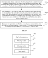
- a map building apparatus includes: a matching module, configured to perform feature point matching on feature points at every two map layers of a plurality of map layers used to build a map, to obtain a plurality of feature point pairs, wherein each feature point pair includes two feature points that are respectively from the two map layers and that match each other, each map layer includes feature points in a plurality of frames of images, and each frame of image carries image information of a target environment; an obtaining module, configured to obtain a target displacement relationship between the two map layers based on map layer space coordinates, at a corresponding map layer, of each feature point in each feature point pair, wherein the map layer space coordinates are obtained based on image coordinates of the feature point in a target image and a relative displacement between capture locations of every two frames of target images, the relative displacement is obtained based on a motion parameter of an image capture component at the image capture locations, the motion parameter is used to indicate a motion status of the image capture component, and the target image is an image
- the two map layers include a first map layer and a second map layer
- the obtaining module includes: a first determining submodule, configured to determine at least one first projection plane based on map layer space coordinates of all feature points that are at the first map layer and that belong to the plurality of feature point pairs, wherein the first determining submodule is configured to determine at least one second projection plane based on map layer space coordinates of all feature points that are at the second map layer and that belong to the plurality of feature point pairs, wherein the at least one first projection plane is in a one-to-one correspondence with the at least one second projection plane, and a plurality of feature points for determining each first projection plane and a plurality of feature points for determining a corresponding second projection plane are feature points that match in a one-to-one manner; a construction submodule, configured to construct a projection error function with respect to a first graphic and a second graphic based on map layer space coordinates of feature points on projection planes that have a correspondence with each other, wherein
- the first determining submodule is configured to: for each pair of a first projection plane and a second projection plane that have a correspondence with each other, construct a projection error subfunction with respect to a first polygon and a second polygon based on map layer space coordinates of a plurality of first feature points on the first projection plane and map layer space coordinates of a plurality of second feature points on the second projection plane, wherein the projection error subfunction is used to represent a relationship that a projection error between the first polygon and the second polygon varies with the displacement relationship, the first polygon is a polygon with a largest area among polygons obtained by connecting the plurality of first feature points, and the second polygon is a polygon with a largest area among polygons obtained by connecting the plurality of second feature points; and determine, as the projection error function, a sum of one or more projection error subfunctions constructed based on at least one pair of a first projection plane and a second projection plane that have a correspondence with each other.
- the obtaining module further includes: a third determining submodule, configured to determine center-of-mass coordinates of the first polygon based on the map layer space coordinates of the plurality of first feature points, wherein the third determining submodule is further configured to determine center-of-mass coordinates of the second polygon based on the map layer space coordinates of the plurality of second feature points.
- a third determining submodule configured to determine center-of-mass coordinates of the first polygon based on the map layer space coordinates of the plurality of first feature points, wherein the third determining submodule is further configured to determine center-of-mass coordinates of the second polygon based on the map layer space coordinates of the plurality of second feature points.
- the first determining submodule is configured to construct the projection error subfunction based on the map layer space coordinates of the plurality of first feature points, the map layer space coordinates of the plurality of second feature points, the center-of-mass coordinates of the first polygon, and the center-of-mass coordinates of the second polygon.
- the first determining submodule is configured to: determine, in all the feature points that are at the first map layer and that belong to the plurality of feature point pairs, an initial plane based on map layer space coordinates of any three unmarked feature points, and add the three unmarked feature points to a first target point set corresponding to the initial plane, wherein all the feature points that are at the first map layer and that belong to the plurality of feature point pairs are initially in an unmarked state; sequentially perform a screening procedure on all other feature points until a total quantity of feature points in the first target point set reaches a preset quantity, to obtain one first target point set, and mark all feature points in the first target point set, wherein the other feature points are feature points in all the unmarked feature points except the three unmarked feature points; repeat the processes of determining an initial plane and performing a screening procedure until all the feature points that are at the first map layer and that belong to the plurality of feature point pairs are marked, to obtain at least one first target point set; and determine a first projection plane based on all feature points
- the screening procedure includes: when a distance from the other feature point to the initial plane is less than a preset distance threshold, determining a plurality of polygons that use, as vertices, the other feature point and all the feature points in the first target point set; and when there is a convex polygon in the plurality of polygons, adding the other feature point to the first target point set to obtain an updated first target point set.
- the first determining submodule is configured to: determine, in all feature points at the second map layer, one second target point set based on each first projection plane, wherein each second target point set includes a plurality of feature points that match a plurality of feature points on the first projection plane in a one-to-one manner; and determine, as a second projection plane corresponding to the corresponding first projection plane, a plane on which the plurality of feature points included in each second target point set are located, to obtain the at least one second projection plane.
- the matching module includes: an obtaining submodule, configured to obtain, based on both a pixel value of any first to-be-matched feature point in a first image and a pixel value of each second to-be-matched feature point in a second image, a specified parameter corresponding to the second to-be-matched feature point, wherein the specified parameter is used to indicate a difference between image information represented by the first to-be-matched feature point and the second to-be-matched feature point, the first image is any image in which the first to-be-matched feature point is located and that is in a plurality of frames of images corresponding to the first map layer, and the second image is any image in which the second to-be-matched feature point is located and that is in a plurality of frames of images corresponding to the second map layer; and a fourth determining submodule, configured to determine, as a feature point that matches the first to-be-matched feature point, a second to-be-matched feature point corresponding to a smallest specified parameter.
- the matching module includes: an obtaining submodule, configured to obtain, based on a pixel value of any first to-be-matched feature point in a first image and a pixel value of any second to-be-matched feature point in a second image, a specified parameter corresponding to the second to-be-matched feature point, wherein the specified parameter is used to indicate a difference between image information represented by the first to-be-matched feature point and the second to-be-matched feature point, the first image is any image in which the first to-be-matched feature point is located and that is in a plurality of frames of images corresponding to the first map layer, and the second image is any image in which the second to-be-matched feature point is located and that is in a plurality of frames of images corresponding to the second map layer; and a fourth determining submodule, configured to: when the specified parameter is less than a first preset threshold, determine that the first to-be-matched feature point matches the second to-be-matched feature point.
- the obtaining submodule is configured to obtain the specified parameter based on a pixel value of each pixel in a first image block and a pixel value of each pixel in a second image block, wherein the first image block includes a pixel corresponding to the first to-be-matched feature point, the second image block includes a pixel corresponding to the second to-be-matched feature point, and a size of the second image block is equal to a size of the first image block.
- both of the first image and the second image are represented by an image pyramid including a plurality of levels of sub-images, and a plurality of levels of sub-images of the first image are in a one-to-one correspondence with a plurality of levels of sub-images of the second image; and the obtaining submodule is configured to: obtain, based on each level of sub-image of the first image and the corresponding level of sub-image of the second image, a specified parameter component of the corresponding level; and determine, as the specified parameter, a sum of specified parameter components corresponding to the plurality of levels of sub-images.
- the specified parameter includes a pixel grayscale difference and/or a descriptor similarity.
- the fusion module is configured to: for at least one of the two map layers, perform coordinate transformation on map layer space coordinates of all feature points at the map layer, so that map layer space coordinates of all feature points on the map that includes feature points at the plurality of map layers are obtained based on a same reference coordinate system.
- the target environment is a parking lot environment.
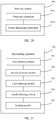
- a map building apparatus includes: a first obtaining module, configured to obtain a plurality of frames of images that carry image information of a target environment, wherein the plurality of frames of images are captured by an image capture component; a second obtaining module, configured to obtain a motion parameter of the image capture component at a capture location of each frame of image, wherein the motion parameter is used to indicate a motion status of the image capture component; a third obtaining module, configured to obtain a relative displacement between capture locations of every two frames of images based on the motion parameter of the image capture component; a fourth obtaining module, configured to obtain, based on the plurality of frames of images and the relative displacement, a map layer including feature points in the plurality of frames of images, wherein the map layer is used to build a map; and a sending module, configured to send the map layer and the relative displacement to a server.
- a first obtaining module configured to obtain a plurality of frames of images that carry image information of a target environment, wherein the plurality of frames of images are captured by an
- the plurality of frames of images are all key-frame images that carry the image information of the target environment
- the first obtaining module is configured to: obtain a plurality of frames of to-be-screened images that carry the image information of the target environment; obtain a target parameter of each frame of to-be-screened image, wherein the target parameter is used to indicate a variation of the to-be-screened image relative to a specified image; and when the target parameter of the to-be-screened image is greater than a second preset threshold, determine the to-be-screened image as a key-frame image.
- the target parameter includes one or more of the following: a time interval between a capture time point of the to-be-screened image and a capture time point of the specified image; an angle variation between an angle of view of the image capture component during capture of the to-be-screened image and an angle of view of the image capture component during capture of the specified image; a relative displacement between a capture location of the to-be-screened image and a capture location of the specified image; a first total quantity of feature points included in the to-be-screened image; and a first ratio of a second total quantity to the first total quantity, wherein the second total quantity is a total quantity of feature points that are in the feature points included in the to-be-screened image and that are different from feature points included in the specified image.
- the plurality of frames of images are adjacent in terms of time sequence
- the specified image corresponding to each frame of to-be-screened image is a frame of key-frame image that is in the plurality of frames of images and that is prior to and closest to the to-be-screened image in terms of time sequence.
- the first obtaining module is configured to: determine a second ratio of the second total quantity to a third total quantity when the target parameter of the to-be-screened image is greater than the second preset threshold, wherein the third total quantity is a total quantity of feature points included in the to-be-screened image, and the second total quantity is the total quantity of the feature points that are in the feature points included in the to-be-screened image and that are different from the feature points included in the specified image; and when the second ratio is greater than a preset ratio, determine the to-be-screened image as the key-frame image.
- a map building system includes a terminal and a server.
- the terminal includes the map building apparatus according to any one of the fourth aspect or the implementations of the fourth aspect
- the server includes the map building apparatus according to any one of the third aspect or the implementations of the third aspect.
- the terminal may be configured on an image capture vehicle, and the image capture vehicle is configured to capture image information of a target environment.
- a map building apparatus including a processor and a memory.
- the processor executes a computer program stored in the memory, a server performs the map building method according to any one of the first aspect or the implementations of the first aspect or performs the map building method according to any one of the second aspect or the implementations of the second aspect.
- a storage medium stores a computer program.
- the computer program instructs a server to perform the map building method according to any one of the first aspect or the implementations of the first aspect or perform the map building method according to any one of the second aspect or the implementations of the second aspect.
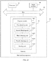
- FIG. 1 is a schematic structural diagram of a map building system used in a map building method according to an embodiment of this application.
- a server 10 and a terminal 20 in the implementation environment.
- a connection may be established between the server 10 and the terminal 20 through a wired or wireless network.
- the server 10 may be one server, a server cluster including several servers, or a cloud computing service center.
- the terminal 20 may be a computer.
- the computer may be a machine having a computing function, such as a general-purpose computer (general-purpose computer), a special-purpose computer (special-purpose computer), a personal computer, or a smartphone.
- the terminal 20 may obtain a plurality of frames of images that carry image information of a target environment, and obtain a motion parameter of an image capture component at capture locations of different images, wherein the motion parameter is used to indicate a motion status of the image capture component; obtain a relative displacement between the capture locations of the different images based on the motion parameter of the image capture component; and obtain, based on the plurality of frames of images and the corresponding relative displacement, a map layer including feature points in the plurality of frames of images, wherein the map layer is used to build a map; and send the map layer and the relative displacement to the server.
- the image capture component may be integrated into the terminal 20. In this case, the terminal 20 may capture an image by using the image capture component, to obtain the image.
- the terminal 20 may be connected to the image capture component. After capturing an image, the image capture component may send the captured image to the terminal 20, so that the terminal 20 obtains the image.
- the image capture component may include a camera.
- the motion parameter may be obtained by using a motion sensor or the camera.
- the target environment may be a parking lot environment, the terminal 20, a camera, and an inertial measurement unit (inertial measurement unit, IMU) may be fixedly disposed on an image capture vehicle, wherein both the camera and the inertial measurement unit are connected to the terminal 20.
- the camera may capture an image of the parking lot environment, and may send the captured image to the terminal 20 after capturing the image of the parking lot environment.
- the inertial measurement unit may obtain a motion parameter of the image capture vehicle in the traveling process, such as a pitch angle (pitch), a roll angle (roll), a yaw angle (yaw), an acceleration, and/or an angular velocity, and send the motion parameter to the terminal 20.
- the motion parameter of the image capture vehicle is a motion parameter of the camera.
- the terminal 20 may determine a motion parameter of the camera at an image capture location of each frame of image by performing spatial location calibration on the image captured by the camera and performing time synchronization processing on the image captured by the camera and the motion parameter obtained by the inertial measurement unit.
- costs of the camera and the inertial measurement unit are relatively low, hardware costs of the map building system can be reduced by capturing an image by the camera and obtaining a motion parameter by the inertial measurement unit.
- the terminal 20 may further perform image preprocessing on the plurality of frames of images, and then send images obtained after image preprocessing to the server 10.
- the image preprocessing may include: obtaining feature points (landmark) from the images, and/or determining a key frame (key frame, KF) image from the plurality of frames of images.
- the key-frame image is an image having an obvious scenario differentiation degree.
- the key-frame image may carry image information, feature point information, timestamp information of the key-frame image, location information of the image capture component when the image capture component captures the key-frame image, posture information of the image capture component when the image capture component captures the key-frame image, and the like.
- the location information of the image capture component when the image capture component captures the key-frame image may be considered as location information of the image capture vehicle when the image capture component captures the key-frame image
- the posture information of the image capture component when the image capture component captures the key-frame image may be considered as posture information of the image capture vehicle when the image capture component captures the key-frame image.
- the posture information may be a motion parameter corresponding to the image capture vehicle, such as a pitch angle, a roll angle, or a yaw angle.
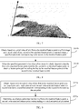
- the server 10 may perform feature point matching on feature points at different map layers based on the map layers sent by the terminal 20 to the server 10, to obtain a plurality of feature point pairs.
- a displacement relationship between every two map layers is obtained based on map layer space coordinates, at a corresponding map layer, of each feature point in the plurality of feature point pairs.
- Map layer fusion is performed on the two map layers based on the displacement relationship, to obtain a map of the target environment.
- Feature points included in each feature point pair are used to represent a same object in the target environment.
- the map layer space coordinates, at the corresponding map layer, of each feature point are obtained based on image coordinates of the feature point in a target image and a relative displacement between capture locations of every two frames of target images.
- the server may be a cloud-side server, so as to process data by using a resource on a cloud side.
- a plurality of map layers may be obtained by capturing images in the parking lot environment for a plurality of times.
- a plurality of feature point pairs may be obtained by performing feature point matching on feature points at different map layers.
- a displacement relationship between the different map layers may be obtained based on map layer space coordinates, at a corresponding map layer, of each feature point in the plurality of feature point pairs.
- a map (also referred to as a localization map layer) of the parking lot may be obtained by performing map layer fusion on the different map layers based on the displacement relationship.
- a plurality of frames of images may be obtained in each image capture process, and a plurality of feature points may be determined based on the plurality of frames of images.
- a relative displacement between the plurality of feature points may be obtained based on a motion parameter obtained by the inertial measurement unit, and then a map layer (also referred to as a submap) including the plurality of feature points may be determined based on the relative displacement and the plurality of feature points.
- each map layer has an anchor point (anchor point, AP).
- the anchor point is a mark point at the map layer.
- an anchor point at each map layer may be a location corresponding to a start moment in each capture process.
- a target displacement relationship between different map layers may be considered as a displacement relationship between anchor points at the different map layers.
- Map layer space coordinates, at a corresponding map layer, of a feature point are space coordinates determined based on a coordinate system established by using an anchor point at the map layer as an origin of coordinates.
- the image capture vehicle captures images of the parking lot environment twice on one day, time periods of the two times of capture are 11:00 to 12:00 and 14:00 to 15:00, a map layer may be determined based on a plurality of frames of images captured from 11:00 to 12:00, another map layer may be determined based on a plurality of frames of images captured from 14:00 to 15:00, and an anchor point at each map layer is a location corresponding to a start moment in a corresponding capture process.
- a feature point is used for describing information having an obvious semantic feature in a target environment.
- Each feature point has a feature point serial number, and the feature point serial number is used to uniquely identify the feature point.
- the feature points may include a semantic feature point and a geometric feature point.
- the semantic feature point may be a set of pixels with an obvious semantic feature in an image.
- semantic feature points used in this embodiment of this application may include sets of pixels used to represent semantic features such as a lane line, a road surface marking, a traffic sign, a vehicle, and a pedestrian.
- a visual geometric feature point may be a set of pixels with an obvious visual feature in an image.
- visual geometric feature points used in this embodiment of this application may include a set of pixels used to represent a point, a straight line, a plane, a broken line, or a corner point (corner point, CP), a set of pixels used to represent a vertex on a lane line segment, and a set of pixels used to represent that an image has obvious black and white contrast.
- the feature points may include a 2D (dimension, dimension) feature point and a 3D feature point.
- the 2D feature point is a feature point in image space.
- the 3D feature point is a feature point on a physical object in three-dimensional space.
- a feature point in this embodiment of this application may be an ORB (oriented FAST and rotated BRIEF, ORB) feature point or the like.
- ORB oriented FAST and rotated BRIEF, ORB
- a grayscale value difference between sufficient neighborhood pixels in a neighborhood of a feature point and the feature point is greater than a preset grayscale threshold, it may be determined that the feature point is an ORB feature point.
- the target environment is a parking lot environment
- the foregoing feature points are used in the map building method provided in this embodiment of this application, compared with a related technology in which semantic feature points such as a lane line and a traffic sign are used, because the parking lot environment includes a relatively large quantity of the foregoing feature points and includes a relatively small quantity of semantic feature points such as a lane line and a traffic sign, a success rate of feature point matching can be increased when feature point matching is performed based on the feature points, thereby avoiding a case in which matching cannot be performed due to a relatively small quantity of feature points.
- a feature point in each frame of image may include at least one pixel in the image.
- a plurality of feature points may exist in each frame of image, and each feature point may also exist in a plurality of frames of images.
- a feature point 1 and a feature point 2 exist in a key frame 1
- the feature point 1, the feature point 2, and a feature point 3 exist in a key frame 2
- the feature point 2 and the feature point 3 exist in a key frame 3
- the feature point 3 exists in a key frame 4.
- the server 10 may also be performed in the terminal 20.
- an action of performing image preprocessing on an image may be performed by the server 10.
- the terminal 20 may directly send the plurality of frames of images and the motion parameter to the server 10.
- the server 10 may obtain a feature point from each frame of image, and determine a key-frame image from the plurality of frames of images, and then perform operations such as obtaining a map layer based on the key-frame image, performing feature point matching, determining a displacement relationship between different map layers, and performing map layer fusion based on the displacement relationship.
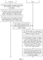
- FIG. 3 is a flowchart of a map building method according to an embodiment of this application.
- a map layer fusion process usually, there are a plurality of to-be-fused map layers.
- a map layer fusion process of a first map layer and a second map layer is used as an example for describing an implementation process of the map building method.
- a map layer fusion process of other to-be-fused map layers correspondingly refer to the map layer fusion process of the first map layer and the second map layer.
- the first map layer and the second map layer are any two of the plurality of map layers.
- the method may include the following steps.
- Step 201 A terminal obtains a plurality of frames of images that carry image information of a target environment.
- the plurality of frames of images may be captured by an image capture component.
- the image capture component may be integrated into the terminal, or the image capture component may be connected to the terminal. After capturing an image, the image capture component may send the captured image to the terminal, so that the terminal obtains the plurality of frames of images.
- the plurality of frames of images may be original images captured by the image capture component, or may be images obtained after screening is performed on the original images.
- all the plurality of frames of images may be key-frame images obtained after screening is performed on the original images captured by the image capture component.
- an implementation process of performing image screening to obtain a key-frame image may include the following steps.
- Step 2011 Obtain a plurality of frames of to-be-screened images that carry the image information of the target environment.
- the plurality of frames of to-be-screened images may be the original images captured by the image capture component.
- the images may be color images (for example, RGB color images) or grayscale images.
- Step 2012. Obtain a target parameter of each frame of to-be-screened image, wherein the target parameter is used to indicate a variation of the to-be-screened image relative to a specified image.
- the target parameter may include one or more of the following: a time interval between a capture time point of the to-be-screened image and a capture time point of the specified image; an angle variation between an angle of view of the image capture component during capture of the to-be-screened image and an angle of view of the image capture component during capture of the specified image; a relative displacement between a capture location of the to-be-screened image and a capture location of the specified image; a first total quantity of feature points included in the to-be-screened image; and a first ratio of a second total quantity to the first total quantity, wherein the second total quantity is a total quantity of feature points that are in the feature points included in the to-be-screened image and that are different from feature points included in the specified image.
- a camera and an inertial measurement unit each have a clock system, and an image capture time point may be determined by using the clock system.
- a motion parameter of the image capture component may be obtained by using the inertial measurement unit, and an angle of view of the image capture component during capture of an image and a relative displacement between a capture location of the image and a capture location of the specified image may be obtained based on the motion parameter.
- the target parameter of the to-be-screened image includes the first total quantity and/or the first ratio
- the feature points in the image may be first obtained, to obtain the first total quantity and/or the first ratio based on the feature points in the image.
- the specified image may be determined depending on an actual requirement.
- the specified image corresponding to each frame of to-be-screened image may be a frame of key-frame image that is in the plurality of frames of images and that is prior to and closest to the to-be-screened image in terms of time sequence.
- the specified image corresponding to each frame of to-be-screened image may be a previous frame of key-frame image of the to-be-screened image.
- the target parameter may include one or more of the following: a time interval between the capture time point of the to-be-screened image and a capture time point of the previous frame of key-frame image; an angle variation between the angle of view of the image capture component during capture of the to-be-screened image and an angle of view of the image capture component during capture of the previous frame of key-frame image; a relative displacement between the capture location of the image and a capture location of the previous frame of key-frame image; the first total quantity of the feature points included in the to-be-screened image; and a first ratio of a second total quantity to the first total quantity, wherein the second total quantity is a total quantity of feature points that are in the feature points included in the to-be-screened image and that are different from feature points included in the previous frame of key-frame image.
- An implementation process of determining whether two feature points are a same feature point may include: calculating parameters such as descriptor (descriptor) similarities of each feature point in the to-be-screened image and each feature point in the specified image; and when the parameters corresponding to the two feature points are greater than a preset parameter threshold, determining that the two feature points are a same feature point.
- a descriptor is used to describe a feature point from a vision perspective. Common descriptors may include an ORB descriptor, a scale-invariant feature transform (scale-invariant feature transform, SIFT) descriptor, and the like.
- the to-be-screened images are screened based on a time interval, an angle variation, a relative displacement, and/or feature point-related information, so that the images can be screened in different capture conditions. For example, images captured when an image capture vehicle is in a plurality of states such as low-speed driving, high-speed driving, straight-line driving, or turning a corner may be screened. Alternatively, images captured in different weather and different light conditions may be screened. Because the images can be screened in different capture conditions, if map layer fusion is performed based on images obtained after screening, precision of a map layer obtained through fusion can be ensured.
- Step 2013 When the target parameter of the to-be-screened image is greater than a second preset threshold, determine the to-be-screened image as a key-frame image.
- the target parameter of the to-be-screened image includes the time interval between the capture time point of the to-be-screened image and the capture time point of the specified image, if the time interval is greater than the second preset threshold, it indicates that there is no key frame within a limited time interval.
- the to-be-screened image may be determined as a key-frame image, and image information included in the to-be-screened image is recorded.
- an angle of view variation of the image capture component may be considered as a rotation angle of the image capture vehicle. If the angle variation is greater than the second preset threshold, it indicates that the rotation angle of the image capture vehicle changes relatively greatly, and that space coordinates of a space point corresponding to a feature point included in the to-be-screened image also change relatively greatly relative to space coordinates of a space point corresponding to a feature point in the specified image.
- the to-be-screened image may be determined as a key-frame image, and image information included in the to-be-screened image is recorded.
- the relative displacement may be considered as a displacement between a location of the image capture vehicle during capture of the to-be-screened image and a location of the image capture vehicle during capture of the specified image. If the relative displacement is greater than the second preset threshold, it indicates that a location of the image capture vehicle changes relatively greatly, and that space coordinates of a space point corresponding to a feature point included in the to-be-screened image also change relatively greatly relative to space coordinates of a space point corresponding to a feature point in the specified image.
- the to-be-screened image may be determined as a key-frame image, and image information included in the to-be-screened image is recorded.
- the target parameter of the to-be-screened image includes the first total quantity of the feature points included in the to-be-screened image
- the first total quantity is greater than the second preset threshold, it indicates that the to-be-screened image includes sufficient feature points.
- the to-be-screened image may be determined as a key-frame image, and image information included in the to-be-screened image is recorded.
- the first ratio is used to reflect a ratio between the feature points that are in the to-be-screened image and that are different from the feature points in the specified image and the feature points that are in the to-be-screened image.
- the first ratio can reflect a coincidence degree between the feature points in the to-be-screened image and the feature points in the specified image. If the first ratio is greater than the second preset threshold, it indicates that the coincidence degree between the feature points in the to-be-screened image and the feature points in the specified image is relatively small, and that image information in the to-be-screened image is of a relatively great reference value.
- the to-be-screened image may be determined as a key-frame image, and image information included in the to-be-screened image is recorded.
- the second preset threshold corresponding to the target parameter of the image may be set depending on an actual requirement.
- the second preset threshold may be 150 milliseconds.
- the second preset threshold may be 30 degrees.
- the target parameter of the image includes the relative displacement between the capture location of the image and the capture location of the specified image, the second preset threshold may be 10 meters.
- a second preset threshold corresponding to each of the plurality of parameters may also be set depending on an actual requirement.
- the to-be-screened image may further be screened; and when the to-be-screened image satisfies a screening condition, the to-be-screened image is determined as a key-frame image to further reduce redundancy of image information. This facilitates sparse calculation in a subsequent feature point matching process, thereby accelerating the feature point matching process.
- the implementation process may include the following steps.
- Step 2013a When the target parameter of the to-be-screened image is greater than the second preset threshold, determine a second ratio of the second total quantity to a third total quantity, wherein the third total quantity is a total quantity of feature points included in the to-be-screened image, and the second total quantity is a total quantity of feature points that are in the feature points included in the to-be-screened image and that are different from feature points included in the specified image.
- the feature points in the to-be-screened image and the feature points in the specified image may be obtained, and then the total quantity of the feature points included in the to-be-screened image is counted to obtain the third total quantity.
- the feature points that are in all the feature points included in the to-be-screened image and that are different from the feature points included in the specified image are determined, and then the total quantity of the different feature points is counted to obtain the second total quantity.
- parameters such as descriptor similarities of each feature point in the to-be-screened image and each feature point in the specified image may be calculated; when the parameters corresponding to the two feature points are greater than the preset parameter threshold, it is determined that the two feature points are a same feature point; and a total quantity of feature points that are in the to-be-screened image and that are the same as those in the specified image is counted, and a difference between the third total quantity and the total quantity of the same feature points is determined as the second total quantity.
- the feature points in the image may be obtained by using an algorithm such as an SIFT algorithm or a Harris corner detection algorithm.
- Step 2013b When the second ratio is greater than a preset ratio, determine the to-be-screened image as a key-frame image.
- the to-be-screened image may be determined as a key-frame image.
- the preset ratio may be determined depending on an actual requirement. For example, the preset ratio may be 20%.
- the target parameter includes at least one of a time interval between image capture time points, an angle variation of angles of view of the image capture component, a relative displacement between image capture locations, and a first total quantity, because the target parameter mainly represents an image variation in a time dimension, an angle dimension, a distance dimension and/or an amount of information.
- the target parameter of the to-be-screened image is greater than the second preset threshold, the to-be-screened image is determined as a key-frame image.
- the key-frame image may further include a relatively large amount of redundancy information.
- the target parameter includes the first ratio
- the second preset threshold is relatively small, a to-be-screened image whose corresponding target parameter is greater than the second preset threshold is determined as a key-frame image.
- the key-frame image may further include a relatively large amount of redundancy information. Therefore, after it is determined that the target parameter of the to-be-screened image is greater than the second preset threshold, the to-be-screened image may further be screened, to further reduce redundancy information.
- the image captured in the time period may be replaced by another image, that is, the image captured in the time period includes a relatively large amount of redundancy information.
- the target parameter is the time interval between the capture time point of the to-be-screened image and the capture time point of the specified image, and duration of the time period is greater than the second preset threshold, the image captured in the time period is determined as a key-frame image.
- the key-frame image may further include a relatively large amount of redundancy information.
- the image whose target parameter is greater than the second preset threshold is further screened, and when a second ratio corresponding to the to-be-screened image is greater than the preset ratio, the to-be-screened image is determined as a key-frame image.
- an image including a relatively large amount of different image information and feature point information may be determined as a key frame, so as to reduce a calculation amount and computation complexity of a subsequent process.
- a value of the preset ratio may be determined depending on an actual requirement.
- the value of the preset ratio may be determined based on an amount of information for map layer fusion. For example, when an initially selected preset ratio is X0, if it is determined, through judgment, that information included in a key-frame image determined based on the preset ratio is insufficient for map layer fusion, the value of the preset ratio may be appropriately reduced, so that information included in a key-frame image determined based on a reduced preset ratio is sufficient for map layer fusion.
- Step 202 The terminal obtains a relative displacement between capture locations of every two frames of images in the plurality of frames of images.
- An implementation process of step 202 may include the following steps.
- Step 2021 Obtain a motion parameter of the image capture component at a capture location of each frame of image.
- the motion parameter is used to indicate a motion status of the image capture component.
- the motion parameter may be a parameter of the image capture component, such as a pitch angle, a roll angle, a yaw angle, an acceleration, and/or an angular velocity.
- the motion parameter of the image capture component may be captured by using the inertial measurement unit.
- the inertial measurement unit may obtain a motion parameter of the image capture vehicle according to first preset frequency.
- the motion parameter of the image capture vehicle measured by the inertial measurement unit is the motion parameter of the image capture component.
- the image capture component may capture an image according to second preset frequency, and a motion parameter of the image capture component at an image capture location of each frame of image may be determined by performing spatial location calibration on the image captured by the image capture component and performing time synchronization processing on the image captured by the image capture component and the motion parameter obtained by the inertial measurement unit.
- Step 2023 Obtain a relative displacement between capture locations of every two frames of images based on the motion parameter of the image capture component.
- the relative displacement between the capture locations of the every two frames of images may be determined based on a motion parameter of each of the two frames of images and a time interval for capturing the two frames of images.
- the plurality of frames of images captured by the image capture component are images that are adjacent in terms of time sequence
- image processing needs to be performed only on every two frames of images that are adjacent in terms of time sequence. Therefore, during obtaining of the relative displacement between the capture locations of the every two frames of images, only a relative displacement between image capture locations of every two frames of images that are adjacent in terms of time sequence needs to be obtained, so as to reduce a calculation amount.
- Step 203 The terminal obtains, based on the plurality of frames of images and the relative displacement, a map layer including a plurality of feature points.
- a feature point in each frame of image may be obtained based on the plurality of frames of images.
- Feature point matching is performed on feature points in the every two frames of images, to determine feature points used to represent a same object in the target environment and a plurality of frames of images in which the feature points are located.
- a displacement relationship between different feature points located in different images may be determined based on all feature points included in each frame of image of the plurality of frames of images and the motion parameter obtained by the inertial measurement unit, and a map layer including a plurality of feature points is established based on the displacement relationship between the different feature points.
- the plurality of frames of images may be images captured in one image capture process.
- the plurality of frames of images are captured in one image capture process, when the displacement relationship between the feature points is determined based on the motion parameter obtained by the inertial measurement unit, accuracy of the determined displacement relationship can be ensured. Moreover, it can be ensured that map layer space coordinates of all the feature points at the map layer are coordinates obtained in one coordinate system, thereby ensuring location reference consistency of all the feature points at the map layer.
- a plurality of feature points included in a second image may be searched for an optimal matching feature point of the first to-be-matched feature point.
- an implementation process of searching for the optimal matching feature point may include the following steps.
- Step 2031a Obtain, based on both a pixel value of the any first to-be-matched feature point in the first image and a pixel value of each second to-be-matched feature point in the second image, a specified parameter corresponding to the second to-be-matched feature point.
- the specified parameter is used to indicate a difference between image information represented by the first to-be-matched feature point and the second to-be-matched feature point.
- the specified parameter may include a pixel grayscale difference and/or a descriptor similarity.
- a value of the specified parameter is a sum of a value of the pixel grayscale difference and a value of the descriptor similarity.
- a descriptor may be an ORB descriptor.
- the ORB descriptor is used to describe an ORB feature point, and the ORB descriptor may include a matrix used to indicate a pixel value relationship between a feature point and a neighborhood pixel, and a gradient direction of a pixel value of the feature point.
- the specified parameter may be obtained based on a pixel value of each pixel in a first image block and a pixel value of each pixel in a second image block.
- the first image block includes a pixel corresponding to the first to-be-matched feature point
- the second image block includes a pixel corresponding to the second to-be-matched feature point
- a size of the second image block is equal to a size of the first image block.
- the size of the image block may be determined depending on an actual requirement, and the feature point may be represented by a pixel in a central region of the image block.
- the first image and the second image each may be represented by an image pyramid including a plurality of levels of sub-images, and a plurality of levels of sub-images of the first image are in a one-to-one correspondence with a plurality of levels of sub-images of the second image.
- an implementation process of obtaining the specified parameter corresponding to the second to-be-matched feature point may include: obtaining, based on each level of sub-image of the first image and the corresponding level of sub-image of the second image, a specified parameter component of the corresponding level; and determining, as the specified parameter, a sum of specified parameter components corresponding to the plurality of levels of sub-images.
- the specified parameter component of the corresponding level is used to indicate a difference between image information represented by the first to-be-matched feature point and the second to-be-matched feature point in the corresponding level of sub-images.
- an image pyramid of a frame of image is a series of image sets from a same original image that are arranged in a pyramid shape and whose resolutions gradually decrease.
- the image pyramid is obtained by performing gradient image downsampling, and the gradient downsampling process ends when a preset termination condition is satisfied.
- a higher level of an image indicates a smaller size of the image, and correspondingly indicates a lower resolution.
- the image pyramid may be a Laplacian pyramid, a Gaussian pyramid, or the like.
- the images are represented by using the image pyramids, so that pixel grayscale differences and descriptor similarities of the two to-be-matched feature points can be separately calculated in case of a plurality of resolutions by using characteristics of the image pyramids. In this way, accuracy of the specified parameter and matching precision can further be improved.
- matching precision and stability can be ensured.
- the matching precision is represented by an absolute value of a matching error, and when the absolute value of the matching error is smaller, the matching precision is higher.
- the matching stability is represented by a probability of incorrect matching, and when the probability of incorrect matching is lower, the matching stability is better.
- a key-frame image Fa includes feature points a1, a2, a3, ..., and an
- a first to-be-matched feature point A is any one of the plurality of feature points, and an image block in which the first to-be-matched feature point A is located is Pa
- a key-frame image Fb includes feature points b1, b2, b3, ..., and bn
- a second to-be-matched feature point B is any one of the plurality of feature points
- an image block in which the second to-be-matched feature point B is located is Pb
- sizes of both the image block Pa and the image block Pb are J
- both of the key-frame image Fa and the key-frame image Fb are represented by an image pyramid including levels 0, 1, ..., and L.
- S l is a pyramid-level scaling coefficient
- S l 0.5 l
- a and b are fixed deviations of the key-frame image Fa and the key-frame image Fb
- P1 is image coordinates of a pixel in the first to-be-matched feature point A
- P2 is image coordinates of a pixel in the second to-be-matched feature point B.
- Pj is offset coordinates of a pixel in an image block
- D is a location mapping relationship of the image block relative to a key-frame image to which the image block belongs, and the mapping relationship is used to indicate a relative location of the image block in the key-frame image.
- (P+DPj) is coordinates, in the key-frame image, of the pixel Pj in the image block, and I(x) is a pixel value of a pixel at coordinates x.
- f(x) is a function for indicating a similarity between pixels.
- the function may be a Euclidean distance function, an amplitude function, a phase function, or the like.
- a pixel grayscale difference corresponding to each pixel in the feature point may be calculated by referring to the formula corresponding to the pixel grayscale difference e1, and a sum of the pixel grayscale differences calculated based on all the pixels is determined as a pixel grayscale difference of the feature point.
- a descriptor similarity corresponding to each pixel in the feature point may be calculated by referring to the formula corresponding to the descriptor similarity e2, and a sum of the descriptor similarities calculated based on all the pixels is determined as a descriptor similarity of the feature point.
- Step 2032a Determine, as a feature point that matches the first to-be-matched feature point, a second to-be-matched feature point corresponding to a smallest specified parameter.
- the second to-be-matched feature point may be determined as a feature point that matches the first to-be-matched feature point.
- the plurality of feature points included in the second image are searched for the optimal matching feature point of the first to-be-matched feature point, and a matching relationship between the first feature point and the corresponding optimal matching feature point is established. In this way, stability and accuracy of feature point matching can be improved.
- the second to-be-matched feature point may further be verified.
- the second to-be-matched feature point succeeds in verification, the second to-be-matched feature point is determined as a feature point that matches the first to-be-matched feature point.
- the smallest specified parameter may be compared with a preset parameter threshold; and when the smallest specified parameter is less than the preset parameter threshold, the second to-be-matched feature point corresponding to the smallest specified parameter is determined as a feature point that matches the first to-be-matched feature point; and/or
- the implementation process may include the following steps.
- Step 2031b Obtain, based on a pixel value of any first to-be-matched feature point in the first image and a pixel value of any second to-be-matched feature point in the second image, a specified parameter corresponding to the second to-be-matched feature point.
- Step 2032b When the specified parameter is less than a first preset threshold, determine that the first to-be-matched feature point matches the second to-be-matched feature point, to obtain a feature point pair including the first to-be-matched feature point and the second to-be-matched feature point.
- step 2031b and step 2032b correspondingly refer to the implementation process of step 2031a and step 2032a. Details are not described herein again.
- Step 204 The terminal sends the map layer and the relative displacement between the capture locations of the every two frames of images to a server.
- the terminal may send, through a communication connection to the server, related information of the first image, related information of the second image, the relative displacement, and the map layer including the plurality of feature points to the server.
- the related information of the image may include information such as information about a pixel in the image, information about a feature point in the image, and a motion parameter of the image capture component during capture of the corresponding image.
- step 201 all the plurality of frames of images in step 202 to step 204 are key-frame images determined based on the screening operation. If no screening operation has been performed on the plurality of frames of obtained original images in step 201, the plurality of frames of images in step 202 to step 204 are the plurality of frames of obtained original images.
- Step 205 The server performs feature point matching on feature points at two map layers to obtain a plurality of feature point pairs.
- Each feature point pair includes two feature points that are respectively from the two map layers and that match each other.
- each feature point pair includes two feature points that are respectively from a first map layer and a second map layer and that match each other.
- a plurality of feature points included at the second map layer may be searched for an optimal matching feature point of the first to-be-matched feature point.
- an implementation process of searching for the optimal matching feature point may include the following steps.
- Step 2051a Obtain, based on both a pixel value of the any first to-be-matched feature point at the first map layer and a pixel value of each second to-be-matched feature point at the second map layer, a specified parameter corresponding to the second to-be-matched feature point.
- step 2051a For an implementation process of step 2051a, correspondingly refer to the implementation process of step 2031a.
- Step 2052a Determine, as a feature point that matches the first to-be-matched feature point, a second to-be-matched feature point corresponding to a smallest specified parameter.
- the second to-be-matched feature point may be determined as a feature point that matches the first to-be-matched feature point.
- the plurality of feature points included at the second map layer are searched for the optimal matching feature point of the first to-be-matched feature point, and a matching relationship between the first feature point and the corresponding optimal matching feature point is established. In this way, stability and accuracy of feature point matching can be improved.
- the second to-be-matched feature point may further be verified.
- the second to-be-matched feature point is determined as a feature point that matches the first to-be-matched feature point.
- the smallest specified parameter may be compared with a preset parameter threshold; and when the smallest specified parameter is less than the preset parameter threshold, and the second to-be-matched feature point corresponding to the smallest specified parameter is determined as a feature point that matches the first to-be-matched feature point; and/or
- the implementation process may include the following steps.
- Step 2051b Obtain, based on a pixel value of any first to-be-matched feature point at the first map layer and a pixel value of any second to-be-matched feature point at the second map layer, a specified parameter corresponding to the second to-be-matched feature point.
- Step 2052b When the specified parameter is less than a first preset threshold, determine that the first to-be-matched feature point matches the second to-be-matched feature point, to obtain a feature point pair including the first to-be-matched feature point and the second to-be-matched feature point.
- Step 206 The server obtains map layer space coordinates, at a corresponding map layer, of a feature point in each feature point pair, and obtains a target displacement relationship between the two map layers based on the map layer space coordinates, at the corresponding map layer, of the feature point in each feature point pair.
- map layer space coordinates, at a map layer, of a feature point may be solved by using a geometrical relationship based on image coordinates of the feature point in a target image corresponding to the map layer and the relative displacement between the capture locations of the every two frames of images in the plurality of frames of target images.
- the map layer space coordinates, at the corresponding map layer, of the feature point may be space coordinates determined based on a coordinate system established by using a specified point (for example, an anchor point) at the map layer as an origin.
- the relative displacement between the capture locations of the two frames of images is obtained based on the motion parameter of the image capture component at the corresponding image capture locations.
- the motion parameter is used to indicate a motion status of the image capture component.
- an implementation process of obtaining the target displacement relationship between the two map layers based on the map layer space coordinates, at the corresponding map layer, of each feature point in each feature point pair may include the following steps.
- Step 2061 Determine at least one first projection plane based on map layer space coordinates of all feature points that are at the first map layer and that belong to the plurality of feature point pairs.
- an implementation process of step 2061 may include the following steps.
- Step 2061a Determine, in all the feature points that are at the first map layer and that belong to the plurality of feature point pairs, an initial plane based on map layer space coordinates of any three unmarked feature points, and add the three unmarked feature points to a first target point set corresponding to the initial plane, wherein all the feature points that are at the first map layer and that belong to the plurality of feature point pairs are initially in an unmarked state.
- a plane can be determined by using any three points. Therefore, in step 2061a1, the initial plane may be determined in all the feature points that are at the first map layer and that belong to the plurality of feature point pairs, based on the map layer space coordinates of the any three unmarked feature points; and the first target point set is created based on the initial plane, wherein the created first target point set is an empty set.
- Step 2061b Sequentially perform a screening procedure on all other feature points until a total quantity of feature points in the first target point set reaches a preset quantity, to obtain one first target point set, and mark all feature points in the first target point set.
- the other feature points are feature points in all the unmarked feature points except the three unmarked feature points.
- the preset quantity may be determined that a plane determined based on all the feature points in the first target point set is an effective plane, wherein a confidence level of the plane is relatively high; and a displacement relationship between the first map layer and the second map layer may be determined based on the effective plane.
- the preset quantity may be determined depending on an actual requirement. For example, the preset quantity may be 10.
- the screening procedure may include the following steps.
- Step b11 When a distance from the other feature point to the initial plane is less than a preset distance threshold, determine a plurality of polygons that use, as vertices, the other feature point and all the feature points in the first target point set.
- the distance from the other feature point to the initial plane may be calculated.
- the distance from the other feature point to the initial plane is less than the preset distance threshold, it may be determined that the other feature point is located on the initial plane within an allowed error range.
- the plurality of polygons that use, as vertices, the other feature point and all the feature points in the first target point set may be determined based on the other feature point and all the feature points in the first target point set.
- whether a corresponding feature point is an effective feature point on the initial plane is determined based on shapes of the plurality of polygons, that is, step b12 is performed.
- Step b12. When there is a convex polygon in the plurality of polygons, add the other feature point to the first target point set to obtain an updated first target point set.
- the other feature point is an effective feature point on the initial plane. Because the plurality of polygons can be determined by using, as vertices, the other feature point and all the feature points in the first target point set, and the convex polygon is in minority in the plurality of polygons, it is determined that a feature point in the convex polygon is an effective feature point on the corresponding plane, and the displacement relationship between the first map layer and the second map layer may be determined based on map layer space coordinates of the other feature point.
- the other feature point may be added to the first target point set, to update the first target point set.
- the first target point set is determined based on the convex polygon, so as to reduce computation complexity and improve calculation precision and stability. For a polygon, any side of the polygon is infinitely extended to both sides of the polygon to obtain a straight line. If all other sides of the polygon are on a same side of the straight line, the polygon is a convex polygon.
- step b11 and step b12 when the distance from the other feature point to the initial plane is less than the preset distance threshold, the other feature point may alternatively be connected to each of any two feature points in the first target point set may alternatively be performed; and when an interior angle formed by the two feature points and the other feature point is less than 180 degrees, after it is determined that there is a convex polygon in the polygons that use, as vertices, the other feature point and all the feature points in the first target point set, the other feature point may be added to the first target point set, to update the first target point set.
- a first target point set includes a point X1, a point X2, and a point X3.
- the another feature point X4 may be connected to both the point X2 and the point X3.
- An interior angle formed by the another feature point X4, the point X2, and the point X3 is an angle ⁇ . It can be learned based on FIG. 14 that the angle ⁇ is less than 180 degrees.
- the another feature point X4 may be added to the first target point set to obtain an updated first target point set including the point X1, the point X2, the point X3, and the another feature point X4.
- Step 2061c Repeat the processes of determining an initial plane and performing a screening procedure until all the feature points that are at the first map layer and that belong to the plurality of feature point pairs are marked, to obtain at least one first target point set.
- Step 2061d Determine a first projection plane based on all feature points in each first target point set to obtain the at least one first projection plane.
- the plane can be determined by using all the feature points in each first target point set, and the plane is the first projection plane determined based on all the feature points in the first target point set.
- the at least one first target point set may be obtained.
- a first projection plane may be determined based on each of the at least one first target point set, to obtain the at least one first projection plane.
- Step 2062 Determine at least one second projection plane based on map layer space coordinates of all feature points that are at the second map layer and that belong to the plurality of feature point pairs.
- the at least one first projection plane is in a one-to-one correspondence with the at least one second projection plane, and a plurality of feature points for determining each first projection plane and a plurality of feature points for determining a corresponding second projection plane are feature points that match in a one-to-one manner.
- an initial plane may be determined based on map layer space coordinates of feature points, and a screening procedure may be performed to obtain the at least one second projection plane.
- step 2062 because all the feature points that are at the second map layer and that belong to the plurality of feature point match, in a one-to-one manner, all the feature points that are at the first map layer and that belong to the plurality of feature point pairs, after the at least one first projection plane is determined based on all the feature points that are at the first map layer and that belong to the plurality of feature point pairs, a second projection plane may be determined based on feature points that match the feature points on each first projection plane, so as to obtain the at least one second projection plane.
- the implementation process may include the following steps.
- Step 2062a Determine, in all feature points at the second map layer, a second target point set based on each first projection plane, wherein each second target point set includes a plurality of feature points that match a plurality of feature points on the first projection plane in a one-to-one manner.
- the plurality of feature points included on the first projection plane may be determined, and the plurality of feature points that match, in a one-to-one manner, the plurality of feature points included on the first projection plane may be determined in the plurality of feature points at the second map layer based on a one-to-one matching relationship between the feature points at the first map layer and the feature points at the second map layer, to obtain a second target point set.
- the at least one second target point set may be determined based on the at least one first projection plane.
- Step 2062b2 Determine, as a second projection plane corresponding to the corresponding first projection plane, a plane on which the plurality of feature points included in each second target point set are located, to obtain the at least one second projection plane.
- a second projection plane may be determined based on the plurality of feature points included in each second target point set, and correspondingly, the at least one second projection plane may be obtained based on at least one target feature.
- Step 2063 Construct a projection error function with respect to a first graphic and a second graphic based on map layer space coordinates of feature points on projection planes that have a correspondence with each other.
- the projection error function is used to represent a relationship that a projection error between the first graphic and the second graphic varies with a displacement relationship between the first map layer and the second map layer
- the first graphic is a graphic that uses, as vertices, all the feature points that are at the first map layer and that belong to the plurality of feature point pairs
- the second graphic is a graphic that uses, as vertices, all the feature points that are at the second map layer and that belong to the plurality of feature point pairs.
- an implementation process of step 2063 may include the following steps.
- Step 2063a Determine center-of-mass coordinates of a first polygon based on map layer space coordinates of a plurality of first feature points on the first projection plane, and determine center-of-mass coordinates of a second polygon based on map layer space coordinates of a plurality of second feature points on the second projection plane.
- the first polygon is a polygon with a largest area among polygons obtained by connecting the plurality of first feature points
- the second polygon is a polygon with a largest area among polygons obtained by connecting the plurality of second feature points.
- a weight corresponding to each first feature point may be determined depending on an actual requirement.
- the weight m corresponding to each feature point may be 1.
- a manner of calculating the center-of-mass coordinates of the second polygon correspondingly refer to the manner of calculating the center-of-mass coordinates of the first polygon.
- Step 2063b For each pair of a first projection plane and a second projection plane that have a correspondence with each other, construct a projection error subfunction with respect to the first polygon and the second polygon based on the map layer space coordinates of the plurality of first feature points on the first projection plane and the map layer space coordinates of the plurality of second feature points on the second projection plane.
- the projection error subfunction is used to represent a relationship that a projection error between the first polygon and the second polygon varies with the displacement relationship between the first map layer and the second map layer.
- the displacement relationship may include a rotation relationship and a translation relationship.
- the projection error subfunction may be constructed based on the map layer space coordinates of the plurality of first feature points, the map layer space coordinates of the plurality of second feature points, the center-of-mass coordinates of the first polygon, and the center-of-mass coordinates of the second polygon.
- the projection subfunction is constructed based on the center-of-mass coordinates, accuracy of a displacement relationship determined based on the projection subfunction can be improved.
- step 2063a may alternatively not be performed.
- Step 2063c Determine, as the projection error function, a sum of one or more projection error subfunctions constructed based on at least one pair of a first projection plane and a second projection plane that have a correspondence with each other.
- Step 2064 Determine, as the target displacement relationship, a displacement relationship that is corresponding to a minimum value of the projection error function.
- the projection error function may be optimized by using an optimization algorithm to obtain a rotation relationship R and a translation relationship T that are corresponding to the minimum value of the projection error function, the rotation relationship R that is corresponding to the minimum value of the projection error function is determined as a rotation relationship in the target displacement relationship, and the translation relationship T that is corresponding to the minimum value of the projection error function is determined as a translation relationship in the target displacement relationship.
- the first map layer and the second map layer each include a plurality of feature points, and map layer space coordinates of each feature point are 3D coordinates
- an implementation process thereof is equivalent to a process of pose solution performed in 3D space.
- the process has relatively high computation complexity and relatively low calculation precision.
- the at least one first projection plane and the at least one second projection plane are determined, and the error function is constructed based on projection planes that have a correspondence with each other, to obtain the target displacement relationship. In this way, computation in 3D space can be converted into calculation on a plane, thereby reducing computation complexity and improving calculation precision and stability.
- Step 207 The server performs map layer fusion on the every two map layers based on the target displacement relationship between the every two map layers, to obtain a map of the target environment.
- an overlapping region at each map layer may be determined.
- coordinate transformation is performed on map layer space coordinates of all feature points at at least one map layer of the every two map layers, so that map layer space coordinates, obtained after the transformation, of all the feature points at the every two map layers are obtained based on a same reference coordinate system.
- a plurality of map layers may be expanded to same coordinates to obtain the map that includes feature points at the plurality of map layers, and map layer space coordinates of all the feature points in the map are all obtained based on a same reference.
- the reference coordinate system may be a coordinate system in which any one of the plurality of map layers is located, or the reference coordinate system may be another specified coordinate system. This is not specifically limited in this embodiment of this application.
- a localization map layer of the parking lot environment can be obtained by using the map building method provided in this embodiment of this application.
- the parking lot localization map layer may be used to describe a current environment of a parking lot by using feature points, and coordinates of all the feature points in the parking lot localization map layer are all determined based on a same coordinate system. Therefore, a location of a to-be-positioned vehicle in the parking lot can be accurately determined by comparing a description of a current environment in which the to-be-positioned vehicle is located with the localization map layer. In this way, the to-be-positioned vehicle can be precisely positioned, thereby ensuring safe driving of the intelligent driving vehicle.
- map building methods provided in the embodiments of this application, feature point matching is performed on the feature points at the every two map layers; the target displacement relationship between the two map layers is obtained based on the map layer space coordinates, at the corresponding map layer, of each feature point in each feature point pair; and map layer fusion is performed on the every two map layers based on the target displacement relationship between the every two map layers.
- the map layer space coordinates of each feature point are obtained based on the image coordinates of the corresponding feature point in the target image and the relative displacement between the capture locations of the every two frames of target images, and the relative displacement is obtained based on the motion parameter of the image capture component at the image capture locations.
- the map layer space coordinates of the feature point do not need to rely on location information, provided by a GPS, of the feature point in the image. This can avoid a problem that reliability of location information determined based on a GPS signal is relatively low because the GPS signal is affected, thereby effectively improving accuracy of the map obtained through map layer fusion.
- the map building method does not need to rely on the location information, provided by the GPS, of the feature points in the image, the method can be applied to a target environment in which there is no GPS signal or a GPS signal is relatively weak, so that the method is applied to a relatively wide range.
- a problem that reliability of location information determined based on a GPS signal is relatively low because the GPS signal in the parking lot environment is affected can be avoided, thereby improving accuracy and precision of an obtained parking lot localization map layer, and effectively ensuring safe driving of an intelligent driving vehicle.
- An embodiment of this application further provides a map building apparatus.
- the apparatus 600 may include:
- the first determining submodule 6021 is configured to:
- the obtaining module 602 may further include:
- the first determining submodule 6021 is configured to construct the projection error subfunction based on the map layer space coordinates of the plurality of first feature points, the map layer space coordinates of the plurality of second feature points, the center-of-mass coordinates of the first polygon, and the center-of-mass coordinates of the second polygon.
- the screening procedure may include: when a distance from the feature point to the initial plane is less than a preset distance threshold, determining a plurality of polygons that use, as vertices, the feature point and all the feature points in the first target point set; and when there is a convex polygon in the plurality of polygons, adding the feature point to the first target point set to obtain an updated first target point set.
- the first determining submodule 6021 is configured to:
- the matching module 601 may include:
- the matching module 601 may include:
- the obtaining submodule 6011 is configured to obtain the specified parameter based on a pixel value of each pixel in a first image block and a pixel value of each pixel in a second image block, wherein the first image block includes a pixel corresponding to the first to-be-matched feature point, the second image block includes a pixel corresponding to the second to-be-matched feature point, and a size of the second image block is equal to a size of the first image block.
- both of the first image and the second image are represented by an image pyramid including a plurality of levels of sub-images, and a plurality of levels of sub-images of the first image are in a one-to-one correspondence with a plurality of levels of sub-images of the second image; and correspondingly, the obtaining submodule 6011 is configured to:
- the specified parameter may include a pixel grayscale difference and/or a descriptor similarity.
- the fusion module 603 is configured to: for at least one of the two map layers, perform coordinate transformation on map layer space coordinates of all feature points at the map layer, so that map layer space coordinates of all feature points on the map that includes feature points at the plurality of map layers are obtained based on a same reference coordinate system.
- the target environment is a parking lot environment.
- the matching module performs feature point matching on the feature points at the every two map layers; the obtaining module obtains the target displacement relationship between the two map layers based on the map layer space coordinates, at the corresponding map layer, of each feature point in each feature point pair; and the fusion module performs map layer fusion on the every two map layers based on the target displacement relationship between the every two map layers.
- the map layer space coordinates of each feature point are obtained based on the image coordinates of the corresponding feature point in the target image and the relative displacement between the capture locations of the every two frames of target images, and the relative displacement is obtained based on the motion parameter of the image capture component at the image capture locations.
- the map layer space coordinates of the feature point do not need to rely on location information, provided by a GPS, of the feature point in the image. This can avoid a problem that reliability of location information determined based on a GPS signal is relatively low because the GPS signal is affected, thereby effectively improving accuracy of the map obtained through map layer fusion.
- the apparatus can be applied to a target environment in which there is no GPS signal or a GPS signal is relatively weak, so that the apparatus is applied to a relatively wide range.
- a problem that reliability of location information determined based on a GPS signal is relatively low because the GPS signal in the parking lot environment is affected can be avoided, thereby improving accuracy and precision of an obtained parking lot localization map layer, and effectively ensuring safe driving of an intelligent driving vehicle.
- An embodiment of this application further provides a map building apparatus.
- the map building apparatus 700 may include:
- the plurality of frames of images are all key-frame images that carry the image information of the target environment, and the first obtaining module 701 is configured to:
- the target parameter may include one or more of the following:
- the plurality of frames of images are adjacent in terms of time sequence
- the specified image corresponding to each frame of to-be-screened image is a frame of key-frame image that is in the plurality of frames of images and that is prior to and closest to the to-be-screened image in terms of time sequence.
- the first obtaining module 701 is configured to:
- the first obtaining module obtains the plurality of frames of images that carry the image information of the target environment; the second obtaining module obtains the motion parameter of the image capture component at the capture location of each frame of image; the third obtaining module obtains the relative displacement between the capture locations of the every two frames of images based on the motion parameter; the fourth obtaining module obtains, based on the plurality of frames of images and the relative displacement, the map layer including the feature points in the plurality of frames of images; and the sending module sends the map layer and the relative displacement to the server.
- the server can obtain map layer space coordinates of a feature point based on image coordinates of the feature point in a target image and the relative displacement between the capture locations of the every two frames of target images, and the relative displacement is obtained based on the motion parameter of the image capture component at the image capture locations. Therefore, compared with a related technology, the map layer space coordinates of the feature point do not need to rely on location information, provided by a GPS, of the feature point in the image. This can avoid a problem that reliability of location information determined based on a GPS signal is relatively low because the GPS signal is affected, thereby effectively improving accuracy of the map obtained through map layer fusion.
- An embodiment of this application further provides a map building apparatus.
- the map building apparatus may include a processor and a memory.
- the memory may store a computer program.
- the map building apparatus can perform the map building methods provided in the embodiments of this application.
- the map building apparatus is configured to perform step 205 to step 207 in the foregoing method embodiment.
- the map building apparatus 20 may include components such as a processor 22, a signal interface 24, a memory 26, and a bus 28. Both the memory 26 and the signal interface 24 are connected to the processor 22 through the bus 28.
- the processor 22 may include one or more processing cores.
- the processor 22 performs various function applications and data processing by running a software program and a module.
- the processor 22 may include one or more of a central processing unit, a digital signal processor, a microprocessor, a microcontroller, or an artificial intelligence processor, and may further optionally include a hardware accelerator for performing an operation, for example, various logic operation circuits.
- the signal interface 24 is configured to establish a connection to another apparatus or module.
- the signal interface 24 may be configured to connect to a transceiver.
- the map building apparatus 20 may further include a transceiver (not shown in the figure).
- the transceiver specifically performs signal receiving and sending.
- the transceiver may be configured to receive, from a terminal, a map layer and a relative displacement between image capture locations.
- the processor 22 may invoke or drive the transceiver to perform corresponding receiving and sending operations.
- the processor 22 when the map building apparatus 20 performs signal receiving and sending, the processor 22 is configured to determine or initiate receiving and sending operations, and acts as an initiator; and the transceiver is configured to perform specific receiving and sending, and acts as a performer.
- the transceiver may alternatively be a transceiver circuit, a radio frequency circuit, or a radio frequency unit. This is not limited in this embodiment.
- the memory 26 may be configured to store a computer program and a module.
- the computer program may be an application program or a drive program.
- the memory 26 may store a program module 262 for at least one function.
- the program module 262 may include a matching unit 2621, an obtaining unit 2622, and a fusion unit 2623.
- the matching unit 2621 has a function that is the same as or similar to that of the matching module 601.
- the matching unit 2621 is configured to perform step 205 in the foregoing method embodiment.
- the obtaining unit 2622 has a function that is the same as or similar to that of the obtaining module 602.
- the obtaining unit 2622 is configured to perform step 206 in the foregoing method embodiment.
- the fusion unit 2623 has a function that is the same as or similar to that of the fusion module 603.
- the fusion unit 2623 is configured to perform step 207 in the foregoing method embodiment.
- An embodiment of this application further provides a map building apparatus.
- the map building apparatus may include a processor and a memory.
- the memory may store a computer program.
- the map building apparatus can perform the map building methods provided in the embodiments of this application.
- the map building apparatus is configured to perform step 201 to step 204 in the foregoing method embodiment.
- the map building apparatus 40 may include components such as a processor 42, a signal interface 44, a memory 46, and a bus 48. Both the memory 46 and the signal interface 44 are connected to the processor 42 through the bus 48.
- the processor 42 may include one or more processing cores.
- the processor 42 performs various function applications and data processing by running a software program and a module.
- the processor 42 may include one or more of a central processing unit, a digital signal processor, a microprocessor, a microcontroller, or an artificial intelligence processor, and may further optionally include a hardware accelerator for performing an operation, for example, various logic operation circuits.
- the signal interface 44 is configured to establish a connection to another apparatus or module.
- the signal interface 44 may be configured to connect to a transceiver.
- the map building apparatus 40 may further include a transceiver (not shown in the figure).
- the transceiver specifically performs signal receiving and sending.
- the transceiver may be configured to send a map layer and a relative displacement between image capture locations to a server.
- the processor 42 may invoke or drive the transceiver to perform corresponding receiving and sending operations.
- the processor 42 when the map building apparatus 40 performs signal receiving and sending, the processor 42 is configured to determine or initiate receiving and sending operations, and acts as an initiator; and the transceiver is configured to perform specific receiving and sending, and acts as a performer.
- the transceiver may alternatively be a transceiver circuit, a radio frequency circuit, or a radio frequency unit. This is not limited in this embodiment.
- the memory 46 may be configured to store a computer program and a module.
- the computer program may be an application program or a drive program.
- the memory 46 may store a program module 462 for at least one function.
- the program module 462 may include a first obtaining unit 4621, a second obtaining unit 4622, a third obtaining unit 4623, a fourth obtaining unit 4624, and a sending unit 4625.
- the first obtaining unit 4621 has a function that is the same as or similar to that of the first obtaining module 701.
- the first obtaining unit 4621 is configured to perform step 201 in the foregoing method embodiment.
- the second obtaining unit 4622 has a function that is the same as or similar to that of the second obtaining module 702.
- the second obtaining unit 4622 is configured to perform step 202 in the foregoing method embodiment.
- the third obtaining unit 4623 has a function that is the same as or similar to that of the third obtaining module 703.
- the third obtaining unit 4623 is configured to perform step 203 in the foregoing method embodiment.
- the fourth obtaining unit 4624 has a function that is the same as or similar to that of the fourth obtaining module 704.
- the fourth obtaining unit 4624 is configured to perform step 204 in the foregoing method embodiment.
- the sending unit 4625 has a function that is the same as or similar to that of the sending module 705.
- the sending unit 4625 is configured to perform step 205 in the foregoing method embodiment.
- the map building apparatus 40 may further include a display screen, a camera component, and the like.
- the display screen is configured to display a UI (User Interface, user interface).
- the display screen may be configured to display an image carrying image information of a target environment.
- the UI may include a graphic, a text, an icon, a video, and any combination thereof.
- the display screen is a touch display screen, the display screen further has a capability of acquiring a touch signal on or above a surface of the display screen.
- the touch signal may be input to the processor as a control signal for processing.
- the display screen may further be configured to provide a virtual button and/or a virtual keyboard, which are/is also referred to as a soft button and/or a soft keyboard.
- the display screen may be a flexible display screen, and is disposed on a curved surface or a folded surface of the map building apparatus.
- the display screen may even be set to a non-rectangular irregular graphic, that is, an irregularly-shaped screen.
- the display screen may be made of a material such as an LCD (Liquid Crystal Display, liquid crystal display) or an OLED (Organic Light-Emitting Diode, organic light-emitting diode).
- the camera component is configured to capture an image or a video.
- the camera is configured to capture an image carrying image information of a target environment.
- the camera component includes a front-facing camera and a rear-facing camera.
- the front-facing camera is disposed on the front panel of the map building apparatus, and the rear-facing camera is disposed on a back face of the map building apparatus.
- the camera component may further include a flash.
- the flash may be a single color temperature flash or a double color temperature flash.
- the double color temperature flash is a combination of a warm light flash and a cold light flash, and may be configured to perform light compensation at different color temperatures.
- An embodiment of this application further provides a storage medium.
- the storage medium may be a non-volatile computer-readable storage medium.
- the storage medium stores a computer program.
- the computer program instructs a server to perform the map building methods provided in the embodiments of this application.
- the foregoing storage medium includes: any medium that can store program code, such as a read-only memory (read-only memory, ROM), a random access memory (random access memory, RAM), a magnetic disk, or an optical disc.
- An embodiment of this application further provides a computer program product including an instruction.
- the computer program product When the computer program product is run on a computer, the computer is enabled to perform the map building methods provided in the embodiments of this application.
- the computer program product may include one or more computer instructions. When the computer program instructions are loaded or executed on the computer, the procedure or functions according to the embodiments of this application are all or partially generated.
- the computer may be a general-purpose computer, a dedicated computer, a computer network, or other programmable apparatuses.
- the computer instruction may be stored in a computer-readable storage medium, or may be transmitted by using the computer-readable storage medium.
- the computer-readable storage medium may be any usable medium accessible by a computer, or a data storage device, such as a server or a data center, integrating one or more usable media.
- the usable medium may be a magnetic medium (for example, a floppy disk, a hard disk, or a magnetic tape), an optical medium (for example, a digital versatile disc (DVD)), a semiconductor medium (for example, a solid-state drive (solid state disk, SSD)), or the like.
- the program may be stored in a computer-readable storage medium.
- the storage medium may include: a read-only memory, a magnetic disk, an optical disc, or the like.
Landscapes
- Engineering & Computer Science (AREA)
- Theoretical Computer Science (AREA)
- Physics & Mathematics (AREA)
- General Physics & Mathematics (AREA)
- Computer Vision & Pattern Recognition (AREA)
- Multimedia (AREA)
- Software Systems (AREA)
- Evolutionary Computation (AREA)
- Artificial Intelligence (AREA)
- Medical Informatics (AREA)
- General Health & Medical Sciences (AREA)
- Databases & Information Systems (AREA)
- Computing Systems (AREA)
- Health & Medical Sciences (AREA)
- Geometry (AREA)
- Computer Graphics (AREA)
- Remote Sensing (AREA)
- Data Mining & Analysis (AREA)
- Life Sciences & Earth Sciences (AREA)
- Bioinformatics & Cheminformatics (AREA)
- Bioinformatics & Computational Biology (AREA)
- Evolutionary Biology (AREA)
- General Engineering & Computer Science (AREA)
- Image Analysis (AREA)
- Processing Or Creating Images (AREA)
Applications Claiming Priority (2)
| Application Number | Priority Date | Filing Date | Title |
|---|---|---|---|
| CN201811458309.XA CN111260779B (zh) | 2018-11-30 | 2018-11-30 | 地图构建方法、装置及系统、存储介质 |
| PCT/CN2019/117160 WO2020108285A1 (zh) | 2018-11-30 | 2019-11-11 | 地图构建方法、装置及系统、存储介质 |
Publications (3)
| Publication Number | Publication Date |
|---|---|
| EP3876142A1 true EP3876142A1 (de) | 2021-09-08 |
| EP3876142A4 EP3876142A4 (de) | 2022-01-05 |
| EP3876142B1 EP3876142B1 (de) | 2026-02-11 |
Family
ID=70854278
Family Applications (1)
| Application Number | Title | Priority Date | Filing Date |
|---|---|---|---|
| EP19891455.8A Active EP3876142B1 (de) | 2018-11-30 | 2019-11-11 | Kartenaufbauverfahren, -einrichtung und -system und speichermedium |
Country Status (5)
| Country | Link |
|---|---|
| US (1) | US12266177B2 (de) |
| EP (1) | EP3876142B1 (de) |
| KR (1) | KR102474160B1 (de) |
| CN (1) | CN111260779B (de) |
| WO (1) | WO2020108285A1 (de) |
Families Citing this family (18)
| Publication number | Priority date | Publication date | Assignee | Title |
|---|---|---|---|---|
| JP7212317B2 (ja) * | 2019-10-11 | 2023-01-25 | トヨタ自動車株式会社 | 車両駐車支援装置 |
| CN113112847B (zh) * | 2021-04-12 | 2025-09-30 | 蔚来汽车科技(安徽)有限公司 | 用于固定泊车场景的车辆定位方法及其系统 |
| CN115409910B (zh) * | 2021-05-28 | 2025-11-18 | 阿里巴巴创新公司 | 一种语义地图构建方法、视觉定位方法及相关设备 |
| CN113252045B (zh) * | 2021-06-25 | 2021-11-02 | 成都睿沿科技有限公司 | 设备定位方法、装置、电子设备及可读存储介质 |
| CN113465617B (zh) * | 2021-07-08 | 2024-03-19 | 上海汽车集团股份有限公司 | 一种地图构建方法、装置及电子设备 |
| CN114119429B (zh) * | 2021-10-28 | 2024-10-18 | 北京三快在线科技有限公司 | 底图处理方法及装置 |
| CN114494485B (zh) * | 2021-12-28 | 2024-11-26 | 北京吉威数源信息技术有限公司 | 多图层数据融合显示方法、装置、设备及存储介质 |
| WO2023131203A1 (zh) * | 2022-01-04 | 2023-07-13 | 深圳元戎启行科技有限公司 | 语义地图更新方法、路径规划方法以及相关装置 |
| CN114565777B (zh) * | 2022-02-28 | 2025-06-24 | 维沃移动通信有限公司 | 数据处理方法和装置 |
| CN115857484A (zh) * | 2022-06-14 | 2023-03-28 | 昆明理工大学 | 基于特征点提取和匹配的多机器人地图融合方法、系统 |
| CN115096286B (zh) * | 2022-06-17 | 2025-08-15 | 深圳市普渡科技有限公司 | 地图合并方法、装置、机器人、存储介质和程序产品 |
| CN117576494A (zh) * | 2022-08-08 | 2024-02-20 | 腾讯科技(深圳)有限公司 | 特征地图生成方法、装置、存储介质和计算机设备 |
| KR102823611B1 (ko) * | 2022-11-10 | 2025-06-23 | 한국전자통신연구원 | 메타버스 가상공연 환경 생성 방법 및 장치 |
| CN116051595B (zh) * | 2022-11-29 | 2025-12-12 | 浙江大华技术股份有限公司 | 一种运动状态确定方法、系统、电子设备及存储介质 |
| CN115797585B (zh) * | 2022-12-19 | 2023-08-08 | 北京百度网讯科技有限公司 | 一种停车场地图生成方法及装置 |
| CN121771347A (zh) * | 2024-09-29 | 2026-03-31 | 华为云计算技术有限公司 | 视频处理方法及相关装置 |
| CN119984298B (zh) * | 2025-04-17 | 2025-08-22 | 重庆长安汽车股份有限公司 | 一种地图的确定方法、装置、车辆及介质 |
| CN120689745B (zh) * | 2025-05-28 | 2026-02-24 | 广州城市信息研究所有限公司 | 基于ai辅助的自然资源要素跨图层指标关联方法及系统 |
Family Cites Families (18)
| Publication number | Priority date | Publication date | Assignee | Title |
|---|---|---|---|---|
| JP2012064131A (ja) * | 2010-09-17 | 2012-03-29 | Tokyo Institute Of Technology | 地図生成装置、地図生成方法、移動体の移動方法、及びロボット装置 |
| CN103123727B (zh) * | 2011-11-21 | 2015-12-09 | 联想(北京)有限公司 | 即时定位与地图构建方法和设备 |
| JP5883673B2 (ja) * | 2012-02-09 | 2016-03-15 | 株式会社ジオ技術研究所 | 3次元地図における地点指定システム |
| US9557419B2 (en) * | 2012-12-18 | 2017-01-31 | Trimble Inc. | Methods for generating accuracy information on an ionosphere model for satellite navigation applications |
| CN103900583B (zh) * | 2012-12-25 | 2018-02-27 | 联想(北京)有限公司 | 用于即时定位与地图构建的设备和方法 |
| CN103559498A (zh) * | 2013-09-24 | 2014-02-05 | 北京环境特性研究所 | 基于多特征融合的快速人车目标分类方法 |
| WO2017022033A1 (ja) * | 2015-07-31 | 2017-02-09 | 富士通株式会社 | 画像処理装置、画像処理方法および画像処理プログラム |
| CN105631811A (zh) * | 2016-02-25 | 2016-06-01 | 科盾科技股份有限公司 | 一种用于图像拼接的方法及装置 |
| JP6772000B2 (ja) * | 2016-08-26 | 2020-10-21 | キヤノン株式会社 | 画像処理装置、画像処理方法およびプログラム |
| CN111108342B (zh) * | 2016-12-30 | 2023-08-15 | 辉达公司 | 用于高清地图创建的视觉测程法和成对对准 |
| WO2018136996A1 (en) * | 2017-01-24 | 2018-08-02 | Pangaea Innovations Pty Ltd | Digital earth framework and indexing schema to extend any "surface" discrete global grid system to construct interoperable "volumetric" discrete global grid systems |
| JP6760114B2 (ja) * | 2017-01-31 | 2020-09-23 | 富士通株式会社 | 情報処理装置、データ管理装置、データ管理システム、方法、及びプログラム |
| CN107025668B (zh) * | 2017-03-30 | 2020-08-18 | 华南理工大学 | 一种基于深度相机的视觉里程计的设计方法 |
| JP6922348B2 (ja) * | 2017-03-31 | 2021-08-18 | 富士通株式会社 | 情報処理装置、方法、及びプログラム |
| US10990829B2 (en) * | 2017-04-28 | 2021-04-27 | Micro Focus Llc | Stitching maps generated using simultaneous localization and mapping |
| CN107741233A (zh) * | 2017-11-10 | 2018-02-27 | 邦鼓思电子科技(上海)有限公司 | 一种三维室外地图的构建方法 |
| CN108665540A (zh) * | 2018-03-16 | 2018-10-16 | 浙江工业大学 | 基于双目视觉特征和imu信息的机器人定位与地图构建系统 |
| CN110555883B (zh) * | 2018-04-27 | 2022-07-22 | 腾讯科技(深圳)有限公司 | 相机姿态追踪过程的重定位方法、装置及存储介质 |
-
2018
- 2018-11-30 CN CN201811458309.XA patent/CN111260779B/zh active Active
-
2019
- 2019-11-11 EP EP19891455.8A patent/EP3876142B1/de active Active
- 2019-11-11 KR KR1020217019684A patent/KR102474160B1/ko active Active
- 2019-11-11 WO PCT/CN2019/117160 patent/WO2020108285A1/zh not_active Ceased
-
2021
- 2021-05-28 US US17/333,811 patent/US12266177B2/en active Active
Also Published As
| Publication number | Publication date |
|---|---|
| KR20210095913A (ko) | 2021-08-03 |
| US20210287350A1 (en) | 2021-09-16 |
| CN111260779B (zh) | 2022-12-27 |
| CN111260779A (zh) | 2020-06-09 |
| EP3876142A4 (de) | 2022-01-05 |
| EP3876142B1 (de) | 2026-02-11 |
| US12266177B2 (en) | 2025-04-01 |
| KR102474160B1 (ko) | 2022-12-02 |
| WO2020108285A1 (zh) | 2020-06-04 |
Similar Documents
| Publication | Publication Date | Title |
|---|---|---|
| US12266177B2 (en) | Map building method, apparatus, and system, and storage medium | |
| JP7422105B2 (ja) | 路側計算装置に用いる障害物3次元位置の取得方法、装置、電子デバイス、コンピュータ可読記憶媒体、及びコンピュータプログラム | |
| KR102694715B1 (ko) | 장애물의 검출 방법, 전자 기기, 노변 기기 및 클라우드 컨트롤 플랫폼 | |
| WO2023016271A1 (zh) | 位姿确定方法、电子设备及可读存储介质 | |
| CN112292711A (zh) | 关联lidar数据和图像数据 | |
| KR20210093194A (ko) | 차량의 차로변경을 탐지하는 방법과 장치, 전자 기기, 저장 장치, 노변 기기, 클라우드 제어 플랫폼 및 프로그램 제품 | |
| CN112184914B (zh) | 目标对象三维位置的确定方法、装置和路侧设备 | |
| CN113240734B (zh) | 一种基于鸟瞰图的车辆跨位判断方法、装置、设备及介质 | |
| WO2023030062A1 (zh) | 一种无人机的飞行控制方法、装置、设备、介质及程序 | |
| JP2021528732A (ja) | 運動物体検出およびスマート運転制御方法、装置、媒体、並びに機器 | |
| CN113128434A (zh) | 一种对单目rgb图像进行3d目标检测的方法 | |
| CN113887400A (zh) | 障碍物检测方法、模型训练方法、装置及自动驾驶车辆 | |
| CN114662587B (zh) | 一种基于激光雷达的三维目标感知方法、装置及系统 | |
| WO2020156923A2 (en) | Map and method for creating a map | |
| CN113870365B (zh) | 相机标定方法、装置、设备以及存储介质 | |
| CN112509126A (zh) | 三维物体检测的方法、装置、设备及存储介质 | |
| CN116259025A (zh) | 一种自动驾驶视觉感知特征提取方法及装置 | |
| CN119722984A (zh) | 一种三维点云地图构建方法、系统、装置及介质 | |
| CN117213507A (zh) | 车辆建图方法、装置、车辆及存储介质 | |
| CN115294234B (zh) | 图像的生成方法、装置、电子设备和存储介质 | |
| CN115578432B (zh) | 图像处理方法、装置、电子设备及存储介质 | |
| KR102750456B1 (ko) | 3차원 시설물 위치 정보를 업데이트하는 방법 및 이를 이용한 장치 | |
| KR102750459B1 (ko) | 3차원 지형지물 위치 정보를 업데이트하는 방법 및 이를 이용한 장치 | |
| CN117152953A (zh) | 一种基于网联车的路侧数据交通分析方法及装置 | |
| KR102748377B1 (ko) | 3차원 시설물 위치 정보를 이용한 모바일 장치의 위치 결정 방법 및 이를 이용한 장치 |
Legal Events
| Date | Code | Title | Description |
|---|---|---|---|
| STAA | Information on the status of an ep patent application or granted ep patent |
Free format text: STATUS: THE INTERNATIONAL PUBLICATION HAS BEEN MADE |
|
| PUAI | Public reference made under article 153(3) epc to a published international application that has entered the european phase |
Free format text: ORIGINAL CODE: 0009012 |
|
| STAA | Information on the status of an ep patent application or granted ep patent |
Free format text: STATUS: REQUEST FOR EXAMINATION WAS MADE |
|
| 17P | Request for examination filed |
Effective date: 20210602 |
|
| AK | Designated contracting states |
Kind code of ref document: A1 Designated state(s): AL AT BE BG CH CY CZ DE DK EE ES FI FR GB GR HR HU IE IS IT LI LT LU LV MC MK MT NL NO PL PT RO RS SE SI SK SM TR |
|
| A4 | Supplementary search report drawn up and despatched |
Effective date: 20211206 |
|
| RIC1 | Information provided on ipc code assigned before grant |
Ipc: G06K 9/46 20060101ALI20211130BHEP Ipc: G05D 1/02 20200101ALI20211130BHEP Ipc: G06K 9/62 20060101ALI20211130BHEP Ipc: G06K 9/00 20060101AFI20211130BHEP |
|
| DAV | Request for validation of the european patent (deleted) | ||
| DAX | Request for extension of the european patent (deleted) | ||
| STAA | Information on the status of an ep patent application or granted ep patent |
Free format text: STATUS: EXAMINATION IS IN PROGRESS |
|
| 17Q | First examination report despatched |
Effective date: 20230912 |
|
| RAP1 | Party data changed (applicant data changed or rights of an application transferred) |
Owner name: SHENZHEN YINWANG INTELLIGENTTECHNOLOGIES CO., LTD. |
|
| REG | Reference to a national code |
Ref country code: DE Free format text: PREVIOUS MAIN CLASS: G06K0009000000 Ref country code: DE Ref legal event code: R079 Ref document number: 602019081324 Country of ref document: DE Free format text: PREVIOUS MAIN CLASS: G06K0009000000 Ipc: G06V0010750000 |
|
| GRAP | Despatch of communication of intention to grant a patent |
Free format text: ORIGINAL CODE: EPIDOSNIGR1 |
|
| STAA | Information on the status of an ep patent application or granted ep patent |
Free format text: STATUS: GRANT OF PATENT IS INTENDED |
|
| RIC1 | Information provided on ipc code assigned before grant |
Ipc: G06V 10/75 20220101AFI20250819BHEP Ipc: G06V 10/80 20220101ALI20250819BHEP Ipc: G06V 20/56 20220101ALI20250819BHEP Ipc: G06V 10/46 20220101ALI20250819BHEP Ipc: G06V 20/40 20220101ALI20250819BHEP |
|
| INTG | Intention to grant announced |
Effective date: 20250901 |
|
| GRAS | Grant fee paid |
Free format text: ORIGINAL CODE: EPIDOSNIGR3 |
|
| GRAA | (expected) grant |
Free format text: ORIGINAL CODE: 0009210 |
|
| STAA | Information on the status of an ep patent application or granted ep patent |
Free format text: STATUS: THE PATENT HAS BEEN GRANTED |
|
| P01 | Opt-out of the competence of the unified patent court (upc) registered |
Free format text: CASE NUMBER: UPC_APP_0019739_3876142/2025 Effective date: 20251230 |
|
| AK | Designated contracting states |
Kind code of ref document: B1 Designated state(s): AL AT BE BG CH CY CZ DE DK EE ES FI FR GB GR HR HU IE IS IT LI LT LU LV MC MK MT NL NO PL PT RO RS SE SI SK SM TR |
|
| REG | Reference to a national code |
Ref country code: CH Ref legal event code: F10 Free format text: ST27 STATUS EVENT CODE: U-0-0-F10-F00 (AS PROVIDED BY THE NATIONAL OFFICE) Effective date: 20260211 Ref country code: GB Ref legal event code: FG4D |
|
| REG | Reference to a national code |
Ref country code: DE Ref legal event code: R096 Ref document number: 602019081324 Country of ref document: DE |
|
| REG | Reference to a national code |
Ref country code: IE Ref legal event code: FG4D |