EP3876322A2 - Dispositif de pile à combustible - Google Patents
Dispositif de pile à combustible Download PDFInfo
- Publication number
- EP3876322A2 EP3876322A2 EP21160859.1A EP21160859A EP3876322A2 EP 3876322 A2 EP3876322 A2 EP 3876322A2 EP 21160859 A EP21160859 A EP 21160859A EP 3876322 A2 EP3876322 A2 EP 3876322A2
- Authority
- EP
- European Patent Office
- Prior art keywords
- fuel
- unit
- fuel cell
- control
- cell
- Prior art date
- Legal status (The legal status is an assumption and is not a legal conclusion. Google has not performed a legal analysis and makes no representation as to the accuracy of the status listed.)
- Withdrawn
Links
- 239000000446 fuel Substances 0.000 title claims abstract description 328
- 230000001105 regulatory effect Effects 0.000 claims abstract description 86
- 230000008859 change Effects 0.000 claims abstract description 44
- 239000007787 solid Substances 0.000 claims abstract description 13
- 239000002737 fuel gas Substances 0.000 claims abstract description 7
- 238000000034 method Methods 0.000 claims description 14
- 238000011088 calibration curve Methods 0.000 claims description 8
- 230000006870 function Effects 0.000 description 53
- 239000001301 oxygen Substances 0.000 description 20
- 229910052760 oxygen Inorganic materials 0.000 description 20
- 238000010586 diagram Methods 0.000 description 17
- QVGXLLKOCUKJST-UHFFFAOYSA-N atomic oxygen Chemical compound [O] QVGXLLKOCUKJST-UHFFFAOYSA-N 0.000 description 14
- 150000002500 ions Chemical class 0.000 description 10
- VNWKTOKETHGBQD-UHFFFAOYSA-N methane Chemical compound C VNWKTOKETHGBQD-UHFFFAOYSA-N 0.000 description 8
- -1 oxygen ions Chemical class 0.000 description 8
- 238000006243 chemical reaction Methods 0.000 description 6
- 230000008054 signal transmission Effects 0.000 description 6
- 230000001419 dependent effect Effects 0.000 description 5
- 238000004891 communication Methods 0.000 description 4
- 239000001257 hydrogen Substances 0.000 description 4
- 229910052739 hydrogen Inorganic materials 0.000 description 4
- 238000005259 measurement Methods 0.000 description 4
- 230000009467 reduction Effects 0.000 description 4
- 230000007423 decrease Effects 0.000 description 3
- 238000005516 engineering process Methods 0.000 description 3
- 230000004913 activation Effects 0.000 description 2
- 239000000919 ceramic Substances 0.000 description 2
- 230000006735 deficit Effects 0.000 description 2
- 239000003792 electrolyte Substances 0.000 description 2
- 150000002431 hydrogen Chemical class 0.000 description 2
- 238000004519 manufacturing process Methods 0.000 description 2
- 239000003345 natural gas Substances 0.000 description 2
- 230000003287 optical effect Effects 0.000 description 2
- 238000006479 redox reaction Methods 0.000 description 2
- 238000001514 detection method Methods 0.000 description 1
- 238000001453 impedance spectrum Methods 0.000 description 1
- 238000012423 maintenance Methods 0.000 description 1
Images


Classifications
-
- H—ELECTRICITY
- H01—ELECTRIC ELEMENTS
- H01M—PROCESSES OR MEANS, e.g. BATTERIES, FOR THE DIRECT CONVERSION OF CHEMICAL ENERGY INTO ELECTRICAL ENERGY
- H01M8/00—Fuel cells; Manufacture thereof
- H01M8/04—Auxiliary arrangements, e.g. for control of pressure or for circulation of fluids
- H01M8/04082—Arrangements for control of reactant parameters, e.g. pressure or concentration
- H01M8/04089—Arrangements for control of reactant parameters, e.g. pressure or concentration of gaseous reactants
-
- H—ELECTRICITY
- H01—ELECTRIC ELEMENTS
- H01M—PROCESSES OR MEANS, e.g. BATTERIES, FOR THE DIRECT CONVERSION OF CHEMICAL ENERGY INTO ELECTRICAL ENERGY
- H01M8/00—Fuel cells; Manufacture thereof
- H01M8/04—Auxiliary arrangements, e.g. for control of pressure or for circulation of fluids
- H01M8/04291—Arrangements for managing water in solid electrolyte fuel cell systems
-
- H—ELECTRICITY
- H01—ELECTRIC ELEMENTS
- H01M—PROCESSES OR MEANS, e.g. BATTERIES, FOR THE DIRECT CONVERSION OF CHEMICAL ENERGY INTO ELECTRICAL ENERGY
- H01M8/00—Fuel cells; Manufacture thereof
- H01M8/04—Auxiliary arrangements, e.g. for control of pressure or for circulation of fluids
- H01M8/04298—Processes for controlling fuel cells or fuel cell systems
- H01M8/04313—Processes for controlling fuel cells or fuel cell systems characterised by the detection or assessment of variables; characterised by the detection or assessment of failure or abnormal function
- H01M8/04537—Electric variables
-
- H—ELECTRICITY
- H01—ELECTRIC ELEMENTS
- H01M—PROCESSES OR MEANS, e.g. BATTERIES, FOR THE DIRECT CONVERSION OF CHEMICAL ENERGY INTO ELECTRICAL ENERGY
- H01M8/00—Fuel cells; Manufacture thereof
- H01M8/04—Auxiliary arrangements, e.g. for control of pressure or for circulation of fluids
- H01M8/04298—Processes for controlling fuel cells or fuel cell systems
- H01M8/04694—Processes for controlling fuel cells or fuel cell systems characterised by variables to be controlled
- H01M8/04746—Pressure; Flow
- H01M8/04753—Pressure; Flow of fuel cell reactants
-
- H—ELECTRICITY
- H01—ELECTRIC ELEMENTS
- H01M—PROCESSES OR MEANS, e.g. BATTERIES, FOR THE DIRECT CONVERSION OF CHEMICAL ENERGY INTO ELECTRICAL ENERGY
- H01M8/00—Fuel cells; Manufacture thereof
- H01M8/10—Fuel cells with solid electrolytes
- H01M8/12—Fuel cells with solid electrolytes operating at high temperature, e.g. with stabilised ZrO2 electrolyte
- H01M2008/1293—Fuel cells with solid oxide electrolytes
-
- Y—GENERAL TAGGING OF NEW TECHNOLOGICAL DEVELOPMENTS; GENERAL TAGGING OF CROSS-SECTIONAL TECHNOLOGIES SPANNING OVER SEVERAL SECTIONS OF THE IPC; TECHNICAL SUBJECTS COVERED BY FORMER USPC CROSS-REFERENCE ART COLLECTIONS [XRACs] AND DIGESTS
- Y02—TECHNOLOGIES OR APPLICATIONS FOR MITIGATION OR ADAPTATION AGAINST CLIMATE CHANGE
- Y02E—REDUCTION OF GREENHOUSE GAS [GHG] EMISSIONS, RELATED TO ENERGY GENERATION, TRANSMISSION OR DISTRIBUTION
- Y02E60/00—Enabling technologies; Technologies with a potential or indirect contribution to GHG emissions mitigation
- Y02E60/30—Hydrogen technology
- Y02E60/50—Fuel cells
Definitions
- a fuel cell device in particular a solid oxide fuel cell device, with at least one cell unit for generating electrical energy from at least one fuel, in particular at least one fuel gas, with at least one electrical sensor unit, in particular at least one resistance sensor unit, which is set up to generate at least one electrical parameter, in particular an electrical direct current resistor, the cell unit, and with at least one control and / or regulating unit, which is set up to at least partially automatically set operating parameters of the cell unit, has been proposed.
- the invention is based on a fuel cell device, in particular a solid oxide fuel cell device, with at least one cell unit for generating electrical energy from at least one fuel, in particular at least one fuel gas, with at least one electrical sensor unit, in particular at least one resistance sensor unit, which is configured to have at least one to detect electrical parameters, in particular an electrical direct current resistance, of the cell unit, and with at least one control and / or regulating unit which is set up to at least partially automatically set operating parameters of the cell unit.
- a fuel cell device in particular a solid oxide fuel cell device
- at least one cell unit for generating electrical energy from at least one fuel, in particular at least one fuel gas
- at least one electrical sensor unit in particular at least one resistance sensor unit, which is configured to have at least one to detect electrical parameters, in particular an electrical direct current resistance, of the cell unit, and with at least one control and / or regulating unit which is set up to at least partially automatically set operating parameters of the cell unit.
- control and / or regulating unit be set up to determine a calorific value of the fuel as a function of a change in the electrical parameter, in particular detected by the electric sensor unit.
- the fuel cell device is preferably designed as a fuel cell, in particular as a solid oxide fuel cell, or as a fuel cell stack, in particular as a solid oxide fuel cell stack, comprising a plurality of fuel cells, in particular solid oxide fuel cells.
- the fuel cell device is designed as a high-temperature fuel cell device.
- the fuel cell device has an operating temperature of at least 500 ° C.
- the cell unit is provided in particular to carry out a chemical reaction of the at least one fuel with an oxygen in order to generate electrical energy.
- the cell unit preferably has at least one ion-conducting element, in particular an electrolyte.
- the ion-conducting element is designed as a solid body.
- the ion-conducting element is preferably formed from a ceramic which is provided in particular to conduct oxygen ions and is impermeable to electrons.
- the cell unit preferably has at least one electrically positively charged electrode, in particular an anode, and at least one electrically negatively charged electrode, in particular a cathode.
- the anode and the cathode are arranged on sides of the ion conduction element facing away from one another, in particular spatially separated from one another by the ion conduction element.
- the fuel cell device has at least one fuel line which is provided to supply the at least one fuel to the anode.
- the fuel cell device has at least one oxygen line which is provided to supply oxygen to the cathode.
- the anode and the cathode are preferably connected to one another in an electrically conductive manner.
- oxygen ions in particular electrically negatively charged
- the oxygen ions on the anode can be mixed with, in particular positively charged, fuel ions, in particular hydrogen ions, in react in a chemical reaction, especially in a redox reaction.
- the flow of ions through the ion-conducting element and the chemical reaction creates an electrical potential difference, in particular an electrical voltage, between the anode and the cathode.
- an electrical current in particular an electrical direct current, can flow between the anode and cathode which are electrically conductively connected to one another.
- the fuel cell device in particular a fuel cell device embodied as a fuel cell stack, can preferably have a plurality of cell units, in particular electrically interconnected with one another.
- “Provided” is to be understood to mean in particular specially equipped and / or specially set up.
- “Set up” is to be understood in particular as specifically programmed and / or specifically designed.
- the fact that an object is provided or set up for a specific function is to be understood in particular to mean that the object fulfills and / or executes this specific function in at least one application and / or operating state.
- the fuel is preferably designed as a fuel gas, in particular as a natural gas, as a hydrogen, as a methane or the like.
- the electrical sensor unit is preferably designed as a resistance sensor unit.
- the electrical parameter of the cell unit is designed as an electrical direct current resistance of the cell unit, which can be directly detected and / or determined by the electrical sensor unit designed as a resistance sensor unit.
- the electrical parameter of the cell unit is designed as an electrical voltage, in particular an electrical direct voltage, of the cell unit or as an electrical current strength, in particular an electrical direct current strength, of the cell unit.
- the electrical sensor unit is alternatively or additionally designed as a voltage sensor unit and / or as a current sensor unit.
- control and / or regulating unit is to be understood as meaning, in particular, a unit with at least one control electronics.
- Control electronics should be understood to mean, in particular, a unit with a processor unit and with a memory unit and with an operating program stored in the memory unit.
- the control and / or regulating unit is set up in particular to at least partially automatically, preferably fully automatically, operating parameters of the cell unit, such as a volume flow of fuel through the cell unit, a volume flow of oxygen through the cell unit, fuel utilization of the cell unit, an operating temperature of the cell unit or the like.
- the control and / or regulating unit is preferably connected to the electrical sensor unit in terms of signal transmission technology, in particular electrically.
- the electrical sensor unit is set up to provide the control and / or regulating unit with a current value of the detected electrical parameter, in particular continuously or at intervals.
- the control and / or regulating unit is preferably set up to compare a value of a currently detected electrical parameter with a value of a previously detected electrical parameter.
- the control and / or regulating unit is set up to determine, in particular to calculate, the calorific value of the fuel as a function of a change in the electrical parameter, in particular the value of the currently recorded electrical parameter compared to the previously recorded electrical parameter.
- the calorific value of the fuel is, in particular, a measure of the chemically bound energy contained in the fuel per unit of measurement, for example the mass and / or volume of the fuel.
- a fuel contains the more chemically bound energy per unit of measurement, the higher the calorific value of the fuel.
- an electrical energy obtained by the cell unit is dependent on the calorific value of the fuel.
- the electrical voltage of the cell unit changes as a function of a change in the calorific value of the fuel, in particular as a function of otherwise constant operating conditions of the cell unit.
- the electrical parameter, in particular the electrical direct current resistance, of the cell unit is dependent on the electrical voltage of the cell unit.
- the electrical voltage of the cell unit, in particular the electrical direct current resistance of the cell unit increases as a function of an increase in the calorific value of the fuel, in particular as a function of otherwise constant operating conditions of the cell unit.
- the electrical voltage of the cell unit in particular the electrical direct current resistance of the cell unit, falls as a function of a reduction in the calorific value of the fuel, in particular as a function of otherwise constant operating conditions of the cell unit.
- calibration parameters can be stored in the storage unit of the control and / or regulating unit, wherein the control and / or regulating unit can be set up to compare the change in the electrical parameter with the calibration parameters in order to determine the calorific value.
- a calorific value of a fuel can advantageously be determined analytically.
- a complex sensor system for direct detection of the calorific value can advantageously be dispensed with.
- a fuel cell device with few components and low maintenance can advantageously be provided. It is advantageously possible to react automatically to fluctuations in a fuel quality, and efficient operation of the fuel cell device can be achieved.
- a user-friendly and user-safe fuel cell device with unstable, in particular fluctuation-prone, fuel supply networks can be provided.
- control and / or regulating unit is set up to determine the calorific value of the fuel as a function of a correlation of the change in the electrical parameter with a modulation of a volume flow of the fuel through the cell unit, in particular through the fuel line.
- the volume flow of the fuel is in particular a measure of a quantity, in particular a volume, of the fuel which flows through a line, in particular through the fuel line.
- the volume flow of the fuel through the cell unit, in particular through the fuel line the greater the more fuel that flows through the cell unit, in particular through the fuel line.
- the modulation of the volume flow of the fuel is in particular a change, in particular an increase or a reduction, in the volume flow of the fuel by a predetermined, in particular predetermined or adjustable value, in particular for a duration of a predetermined time interval.
- the change in the electrical parameter depends on the modulation of the volume flow of the fuel through the cell unit, in particular of a type of modulation, for example a sinusoidal modulation, a triangular modulation, a trapezoidal modulation or the like.
- the electrical parameter depends on the volume flow of the fuel through the cell unit and on the calorific value of the fuel.
- the electrical parameter changes as a function of a modulation of a volume flow of a first fuel with a first calorific value by a predetermined value with a different strength than as a function of a modulation of a volume flow of a second fuel with a second calorific value different from the first calorific value the specified value.
- the electrical parameter preferably changes as a function of a modulation of a volume flow of a first fuel with a first calorific value by a predetermined value than as a function of a modulation of a volume flow of a second fuel with a second calorific value that is lower than the first calorific value the specified value.
- control and / or regulating unit is set up to take into account the correlation of the change in the electrical parameter with the modulation of the volume flow of the fuel through the cell unit in order to determine the calorific value of the fuel.
- a particularly precise determination of the calorific value can advantageously be made possible.
- the fuel cell device comprises at least one metering unit, which is provided to set a volume flow of the fuel through the cell unit, in particular through the fuel line, the control and / or regulating unit being set up to modulate the metering unit in a targeted manner of the volume flow by a specified value.
- the metering unit can be provided to modulate the volume flow of the fuel through the cell unit, in particular through the fuel line, sinusoidally, triangularly, trapezoidally or in some other way that appears sensible to a person skilled in the art.
- the metering unit is preferably arranged on the fuel line or on a fuel storage unit of the fuel cell device.
- the metering unit can be provided to completely prevent a volume flow through the cell unit, in particular through the fuel line, in particular to completely close the fuel line.
- the dosing unit is preferably can be operated by a motor, in particular as a function of activation by the control and / or regulating unit.
- the metering unit can in particular be designed as a valve, as a pump, as a controlled flap or as another metering unit that appears sensible to a person skilled in the art.
- the control and / or regulating unit is preferably set up to determine the gross calorific value of the fuel as a function of a change in the electrical parameter as a result of the modulation of the volume flow of the fuel and as a function of the modulation of the volume flow of the fuel by the predetermined value.
- the control and / or regulating unit is preferably set up to control the metering unit for targeted modulation of the volume flow during breaks in operation of the cell unit.
- control and / or regulating unit is set up to control the metering unit for a targeted modulation of the volume flow by a low predetermined value and / or with a high modulation frequency, with the cell unit being operated by modulating the volume flow Without impairment or a performance of the cell unit remains at least above a performance minimum value.
- an output of the cell unit is increased at least during the modulation of the volume flow from a normal operating output by at least a value by which the output of the cell unit decreases at most as a function of the modulation of the volume flow.
- a targeted modulation of the volume flow of the fuel and a targeted determination of the calorific value of the fuel can advantageously be made possible.
- control and / or regulating unit is set up to compare the change in the electrical parameter as a function of the targeted modulation of the volume flow to determine the calorific value of the fuel with calibration parameters, in particular with calibration curves.
- the calibration parameters in particular the calibration curves, are preferably stored in the memory unit of the control and / or regulating unit.
- the calibration parameters are stored separately from the fuel cell device, for example on a cloud server, and that the fuel cell device in particular has a communication unit via which the control and / or regulating unit can access the calibration parameters.
- the control and / or regulating unit is set up to determine the current calorific value of the fuel to read out a calorific value stored in a calibration parameter, the calibration parameter the stored calorific value depending on a modulation of the volume flow by a value that corresponds to a value of the current Corresponds to modulation of the volume flow, and as a function of a change in the electrical parameter by a value that corresponds to a value of the current change in the electrical parameter.
- control and / or regulating unit is set up to set the operating parameters of the cell unit as a function of the determined calorific value of the fuel.
- control and / or regulating unit is set up to control components of the fuel cell device, for example the fuel line, the oxygen line, the metering unit, the anode, the cathode or the like in order to set the operating parameters of the cell unit.
- control and / or regulating unit is set up to set a volume flow of the fuel through the cell unit and / or a volume flow of the oxygen through the cell unit as a function of the determined calorific value of the fuel.
- target operating parameters of the cell unit assigned to different calorific values can be stored in the storage unit of the control and / or regulating unit.
- the control and / or regulating unit is preferably set up to compare the calorific value determined with the stored calorific value and to regulate the operating parameters of the cell unit to the nominal operating parameters assigned to the calorific value determined.
- a fuel cell device that can be operated with an advantageously high degree of efficiency and / or with an extended service life can be provided.
- control and / or regulating unit be set up to create calibration parameters, in particular of calibration curves, correlations of the change in the electrical parameter with a modulation of a volume flow of fuels of different calorific values through the cell unit.
- control and / or regulating unit is set up to store the correlations of the change in the electrical parameter with a modulation of a volume flow of fuels of different calorific values by the cell unit in the storage unit of the control and / or regulating unit.
- the control and / or regulating unit is preferably set up to determine the calibration parameters, in particular by detecting the correlations of the change in the electrical parameter with a modulation of a volume flow of fuels of different calorific values through the cell unit.
- control and / or regulating unit is set up to receive the correlations of the change in the electrical parameter with a modulation of a volume flow of fuels of different calorific values by the cell unit for storage, in particular via the communication unit from a cloud Server, an external storage medium or the like, or that the correlations of the change in the electrical parameter with a modulation of a volume flow of fuels of different calorific values by the cell unit during a manufacturing process of the fuel cell device are stored by the control and / or regulating unit.
- Calibration parameters can advantageously be created for an efficient determination of calorific values.
- the fuel cell device comprises at least one flow sensor unit, which is set up to detect the volume flow through the cell unit, in particular in an operating range of the cell unit, at least to create the calibration parameters.
- the flow sensor unit is preferably set up to detect the volume flow of the fuel through the fuel line.
- the flow sensor unit is connected to the control and / or regulating unit in terms of signal transmission, in particular electrically.
- the flow sensor unit can in particular be designed as an optical flow sensor, as a mechanical flow sensor, as an electrical flow sensor or as another flow sensor that appears to be useful to a person skilled in the art.
- an "operating range" of the cell unit is intended to mean, in particular, a range around an operating point of the cell unit with a deviation of at most 15% from the operating point, preferably of at most 10% from the operating point and particularly preferably of at most 5% from the operating point.
- the flow sensor unit is set up to detect a plurality of different volume flows of different fuels with different calorific values.
- the electric sensor unit is set up to record a plurality of different values of the electrical characteristic variable depending on the different volume flows of the different fuels with the different calorific values in order to create the calibration parameters.
- control and / or regulating unit is set up to store the values recorded by the flow sensor unit and by the electric sensor unit for creating the calibration parameters as correlations of the change in the electrical parameter with a modulation of a volume flow of fuels of different calorific values through the cell unit.
- Particularly precise calibration parameters in particular those matched to the respective fuel cell device, can advantageously be provided.
- the invention is also based on a fuel cell system with a plurality of fuel cell devices according to the invention.
- the fuel cell system can in particular be designed as a fuel cell stack with a plurality of fuel cell devices designed as fuel cells or as a fuel cell system with a plurality of fuel cell devices designed as fuel cell stacks.
- the fuel cell system can preferably comprise further components that appear useful in particular to a person skilled in the art, such as for example at least one heat exchanger, at least one reformer, at least one direct current / alternating current inverter or the like.
- a fuel cell system that can be operated efficiently, in particular with unstable fuel supply networks, can advantageously be provided.
- control and / or regulating units of the fuel cell devices are set up to set modulations of volume flows of the fuel in two fuel cell devices in each case opposite to one another.
- control and / or regulating units of the fuel cell devices are connected to one another in terms of signal transmission technology, in particular electrically.
- the fuel cell system comprises a single control and / or regulating unit which is set up to control and / or regulate all components, in particular cell units, of the fuel cell devices of the fuel cell system.
- a control and / or regulating unit of a first fuel cell device is preferably set up to increase the volume flow of the fuel by a predetermined value in order to modulate a volume flow of a fuel through the cell unit of the first fuel cell device.
- a control and / or regulating unit of a second fuel cell device is preferably set up to reduce the volume flow of the fuel, in particular by the same predetermined value, in order to modulate a volume flow of the fuel through a cell unit of the second fuel cell device. Electrical voltage fluctuations in the fuel cell system due to a modulation of a volume flow can advantageously be compensated for and prevented.
- a fuel cell system that can be operated in a particularly stable manner, in particular with low voltage fluctuations, can advantageously be provided.
- the invention is based on a method for operating a fuel cell device, in particular a fuel cell device according to the invention.
- a calorific value of a fuel is determined in at least one method step as a function of a change in at least one electrical parameter of at least one, in particular the aforementioned, cell unit of the fuel cell device.
- a method for efficient operation of the fuel cell device can advantageously be provided.
- the fuel cell device according to the invention, the fuel cell system according to the invention and / or the method according to the invention should / should not be restricted to the application and embodiment described above.
- the fuel cell device according to the invention, the fuel cell system according to the invention and / or the method according to the invention can fulfill a mode of operation described herein have a number that differs from a number of individual elements, components and units as well as method steps mentioned herein.
- values lying within the stated limits should also be deemed disclosed and can be used in any way.
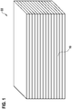
- FIG. 1 shows a fuel cell system 22 in a schematic perspective illustration.
- the fuel cell system 22 comprises a plurality of fuel cell devices 10.
- the fuel cell system 22 can in particular be configured as a fuel cell stack with a plurality of fuel cell devices 10 configured as fuel cells or as a fuel cell system with a plurality of fuel cell devices 10 configured as fuel cell stacks.
- the fuel cell system 22 can preferably include further components that appear useful in particular to a person skilled in the art, such as at least one heat exchanger, at least one reformer, at least one direct current / alternating current inverter or the like (not shown here).
- FIG. 8 shows a sectional view of a fuel cell device 10, in particular a solid oxide fuel cell device, of the fuel cell system 22 from FIG Figure 1 in a schematic representation.
- the fuel cell device 10 preferably comprises at least one cell unit 12 for generating electrical energy from at least one fuel, in particular at least one fuel gas, at least one electrical sensor unit 14, in particular at least one resistance sensor unit, which is designed to measure at least one electrical parameter, in particular an electrical direct current resistance, of the cell unit 12, and at least one control and / or regulating unit 16 which is set up to at least partially automatically set operating parameters of the cell unit 12.
- the control and / or regulating unit 16 is preferably set up to determine a calorific value of the fuel as a function of a change in the electrical parameter detected, in particular by the electric sensor unit 14.
- the fuel cell device 10 is preferably designed as a fuel cell, in particular as a solid oxide fuel cell, or as a fuel cell stack, in particular as a solid oxide fuel cell stack, comprising a plurality of fuel cells, in particular solid oxide fuel cells.
- the fuel cell device 10 is designed as a high-temperature fuel cell device.
- the fuel cell device 10 an operating temperature of at least 500 ° C.
- the cell unit 12 is provided in particular to carry out a chemical reaction of the at least one fuel with an oxygen in order to generate electrical energy.
- the cell unit 12 preferably has at least one ion-conducting element 24, in particular an electrolyte.
- the ion-conducting element 24 is designed as a solid body.
- the ion-conducting element 24 is preferably formed from a ceramic which is provided in particular to conduct oxygen ions and is impermeable to electrons.
- the cell unit 12 preferably has at least one electrically positively charged electrode, in particular an anode 26, and at least one electrically negatively charged electrode, in particular a cathode 28.
- the anode 26 and the cathode 28 are arranged on sides of the ion conducting element 24 facing away from one another, in particular spatially separated from one another by the ion conducting element 24.
- the fuel cell device 10 has at least one fuel line 30 which is provided to supply the at least one fuel to the anode 26.
- a flow direction of the fuel through the fuel line 30 is shown in FIG Figure 2 illustrated in particular by means of a first arrow 32.
- the fuel cell device 10 has at least one oxygen line 34, which is provided to supply oxygen to the cathode 28.
- a flow direction of the oxygen through the oxygen pipe 34 is shown in FIG Figure 2 illustrated in particular by means of a second arrow 36.
- the anode 26 and the cathode 28 are preferably connected to one another in an electrically conductive manner, in particular via an electrical conduction element 38 of the fuel cell device 10.
- oxygen ions in particular negatively charged electrically
- the oxygen ions at the anode 26 can react with, in particular electrically positively charged, fuel ions, in particular hydrogen ions, in a chemical reaction, in particular in a redox reaction.
- the flow of ions through the ion conducting element 24 and the chemical reaction creates an electrical potential difference, in particular an electrical voltage, between the anode 26 and the cathode 28.
- an electric current in particular an electrical direct current, between the electrically conductively connected anode 26 and cathode 28 flow.
- the fuel cell device 10 in particular a fuel cell device 10 configured as a fuel cell stack, can preferably have a plurality of cell units 12, in particular electrically interconnected with one another. In Figure 2 a single cell unit 12 is shown for the sake of clarity.
- the fuel is preferably designed as a fuel gas, in particular as a natural gas, as a hydrogen, as a methane or the like.
- the electrical sensor unit 14 is preferably designed as a resistance sensor unit.
- the electrical parameter of the cell unit 12 is designed as an electrical direct current resistance of the cell unit 12, which can be directly detected and / or determined by the electrical sensor unit 14 designed as a resistance sensor unit.
- the electrical parameter of the cell unit 12 is embodied as an electrical voltage, in particular an electrical direct voltage, of the cell unit 12 or as an electrical current strength, in particular an electrical direct current strength, of the cell unit 12.
- the electrical sensor unit 14 is alternatively or additionally designed as a voltage sensor unit and / or as a current sensor unit.
- the control and / or regulating unit 16 is set up in particular to at least partially automatically, preferably fully automatically, operating parameters of the cell unit 12, such as a volume flow of the fuel through the cell unit 12, a volume flow of the oxygen through the cell unit 12, a fuel utilization of the cell unit 12, an operating temperature of the cell unit 12 or the like. To set.
- the control and / or regulating unit 16 is preferably connected to the electrical sensor unit 14 in terms of signal transmission, in particular electrically.
- the electrical sensor unit 14 is set up to provide the control and / or regulating unit 16 with a current value of the detected electrical parameter, in particular continuously or at intervals.
- the control and / or regulating unit 16 is preferably set up to compare a value of a currently detected electrical parameter with a value of a previously detected electrical parameter.
- the control and / or regulating unit 16 is set up as a function of a change in the electrical parameter, in particular the value of the currently recorded electrical parameter compared to the value of the previously recorded electrical parameter, to determine the calorific value of the fuel, in particular to calculate it.
- the calorific value of the fuel is, in particular, a measure of the chemically bound energy contained in the fuel per unit of measurement, for example the mass and / or volume of the fuel.
- a fuel contains the more chemically bound energy per unit of measurement, the higher the calorific value of the fuel.
- an electrical energy obtained by the cell unit 12, in particular an electrical voltage of the cell unit 12, is dependent on the calorific value of the fuel.
- the electrical voltage of the cell unit 12 changes as a function of a change in the calorific value of the fuel, in particular as a function of otherwise constant operating conditions of the cell unit 12.
- the electrical parameter, in particular the electrical direct current resistance, of the cell unit 12 is dependent on the electrical voltage of the Cell unit 12.
- the electrical voltage of cell unit 12, in particular the electrical direct current resistance of cell unit 12 increases as a function of an increase in the calorific value of the fuel, in particular as a function of otherwise constant operating conditions of cell unit 12.
- the electrical voltage of cell unit 12 decreases, in particular the electrical direct current resistance of the cell unit 12 as a function of a reduction in the calorific value of the fuel, in particular as a function of otherwise constant operating conditions de r cell unit 12.
- calibration parameters can be stored in a memory unit 40 of the control and / or regulating unit 16, wherein the control and / or regulating unit 16 can be set up to determine the calorific value of the change in the electrical parameter with the calibration parameters to compare.
- the control and / or regulating unit 16 is preferably set up to determine the calorific value of the fuel as a function of a correlation of the change in the electrical parameter with a modulation of a volume flow of the fuel through the cell unit 12, in particular through the fuel line 30.
- the volume flow of the fuel is in particular a measure of an amount in particular for a volume of the fuel which flows through a line, in particular through the fuel line 30.
- the volume flow of the fuel through the cell unit 12, in particular through the fuel line 30, the greater the more fuel that flows through the cell unit 12, in particular through the fuel line 30.
- the modulation of the volume flow of the fuel is in particular a change, in particular an increase or a reduction, in the volume flow of the fuel by a predetermined, in particular predetermined or adjustable value, in particular for a duration of a predetermined time interval.
- the change in the electrical parameter depends on the modulation of the volume flow of the fuel through the cell unit 12, in particular on a type of modulation, for example a sinusoidal modulation, a triangular modulation, a trapezoidal modulation or the like.
- the electrical parameter is dependent on the volume flow of the fuel by the cell unit 12 and the calorific value of the fuel.
- the electrical parameter changes as a function of a modulation of a volume flow of a first fuel with a first calorific value by a predetermined value with a different strength than as a function of a modulation of a volume flow of a second fuel with a second calorific value different from the first calorific value the specified value.
- the electrical parameter preferably changes as a function of a modulation of a volume flow of a first fuel with a first calorific value by a predetermined value than as a function of a modulation of a volume flow of a second fuel with a second calorific value that is lower than the first calorific value the specified value (cf. Figure 3 ).
- the control and / or regulating unit 16 is set up to take into account the correlation of the change in the electrical parameter with the modulation of the volume flow of the fuel through the cell unit 12 in order to determine the calorific value of the fuel.
- the fuel cell device 10 preferably comprises at least one metering unit 18, which is provided to set a volume flow of the fuel through the cell unit 12, in particular through the fuel line 30, the control and / or regulating unit 16 being configured to convert the metering unit 18 into one targeted modulation of the volume flow by a specified value head for.
- the metering unit 18 can be provided to modulate the volume flow of the fuel through the cell unit 12, in particular through the fuel line 30, sinusoidally, triangularly, trapezoidally or in some other way that appears sensible to a person skilled in the art.
- the metering unit 18 is preferably arranged on the fuel line 30, as for example in the present exemplary embodiment, or on a fuel storage unit of the fuel cell device 10.
- the metering unit 18 can be provided to completely prevent a volume flow through the cell unit 12, in particular through the fuel line 30, in particular to completely close the fuel line 30.
- the metering unit 18 can preferably be actuated by a motor, in particular as a function of activation by the control and / or regulating unit 16.
- the metering unit 18 can in particular be used as a valve, as a pump, as a controlled flap or as another, a person skilled in the art appearing dosing unit be formed.
- the control and / or regulating unit 16 is preferably set up to determine the gross calorific value of the fuel as a function of a change in the electrical parameter as a result of the modulation of the volume flow of the fuel and as a function of the modulation of the volume flow of the fuel by the specified value.
- the control and / or regulating unit 16 is preferably set up to control the metering unit 18 for a targeted modulation of the volume flow during breaks in operation of the cell unit 12.
- control and / or regulating unit 16 is set up to control the metering unit 18 for a targeted modulation of the volume flow by a low predetermined value and / or with a high modulation frequency, with the cell unit 12 being operated by the Modulation of the volume flow without impairment or the output of the cell unit 12 remains at least above a minimum output value.
- an output of the cell unit 12 is increased from a normal operating output at least during the modulation of the volume flow by at least a value by which the output of the cell unit 12 decreases at most depending on the modulation of the volume flow.
- the control and / or regulating unit 16 is preferably set up to determine the change in the electrical parameter as a function of the targeted modulation of the volume flow to determine the calorific value of the fuel with calibration parameters, especially with calibration curves.
- the calibration parameters in particular the calibration curves, are preferably stored in the memory unit 40 of the control and / or regulating unit 16.
- the calibration parameters are stored separately from the fuel cell device 10, for example on a cloud server, and that the fuel cell device 10 in particular has a communication unit via which the control and / or regulating unit 16 can access the calibration parameters (not shown here).
- the calibration parameters describe changes in the electrical parameter as a function of different fuels with different calorific values and as a function of modulations of volume flows of the fuels by different predetermined values.
- the control and / or regulating unit 16 is set up to determine the current calorific value of the fuel to read out a calorific value stored in a calibration parameter, the calibration parameter the stored calorific value depending on a modulation of the volume flow by a value that corresponds to a value of the corresponds to the current modulation of the volume flow, and as a function of a change in the electrical parameter by a value that corresponds to a value of the current change in the electrical parameter.
- the control and / or regulating unit 16 is preferably set up to set the operating parameters of the cell unit 12 as a function of the determined calorific value of the fuel.
- the control and / or regulating unit 16 is set up to set the operating parameters of the cell unit 12 components of the fuel cell device 10, for example the fuel line 30, the oxygen line 34, the metering unit 18, the anode 26, the cathode 28 or the like. , head for.
- the control and / or regulating unit 16 is set up to set a volume flow of the fuel through the cell unit 12 and / or a volume flow of the oxygen through the cell unit 12 as a function of the determined calorific value of the fuel.
- target operating parameters of the cell unit 12 assigned to different calorific values can be stored in the memory unit 40 of the control and / or regulating unit 16.
- the control and / or regulating unit 16 is preferably set up to combine the determined calorific value with the stored To compare calorific values and to regulate the operating parameters of the cell unit 12 to the setpoint operating parameters assigned to the determined calorific value.
- the control and / or regulating unit 16 is preferably set up to store correlations of the change in the electrical parameter with a modulation of a volume flow of fuels of different calorific values through the cell unit 12 in order to create calibration parameters, in particular calibration curves.
- the control and / or regulating unit 16 is set up to store the correlations of the change in the electrical parameter with a modulation of a volume flow of fuels of different calorific values by the cell unit 12 in the storage unit 40 of the control and / or regulating unit 16.
- the control and / or regulating unit 16 is preferably set up to determine the calibration parameters, in particular by detecting the correlations of the change in the electrical parameter with a modulation of a volume flow of fuels of different calorific values through the cell unit 12 the control and / or regulating unit 16 is set up to receive the correlations of the change in the electrical parameter with a modulation of a volume flow of fuels of different calorific values by the cell unit 12 for storage, in particular via the communication unit from a cloud server, an external one Storage medium or the like, or that the correlations of the change in the electrical parameter with a modulation of a volume flow of fuels of different calorific values through the cell unit 12 during a manufacturing process of the fuel cell device 10 from the St. Your and / or control unit 16 are stored.
- the fuel cell device 10 preferably comprises at least one flow sensor unit 20 which is set up to detect the volume flow through the cell unit 12, in particular in an operating range of the cell unit 12, at least to create the calibration parameters.
- the flow sensor unit 20 is preferably set up to detect the volume flow of the fuel through the fuel line 30.
- the flow sensor unit 20 is connected to the control and / or regulating unit 16 in terms of signal transmission technology, in particular electrically.
- the flow sensor unit 20 can in particular be designed as an optical flow sensor, as a mechanical flow sensor, as an electrical flow sensor or as another flow sensor that appears sensible to a person skilled in the art.
- the flow sensor unit 20 is set up to detect a plurality of different volume flows of different fuels with different calorific values.
- the electrical sensor unit 14 is set up to record a plurality of different values of the electrical parameter depending on the different volume flows of the different fuels with the different calorific values in order to create the calibration parameters.
- the control and / or regulating unit 16 is set up to use the values recorded by the flow sensor unit 20 and by the electric sensor unit 14 to create the calibration parameters as correlations of the change in the electrical parameter with a modulation of a volume flow of fuels of different calorific values through the cell unit 12 save.
- the control and / or regulating units 16 of the fuel cell devices 10, in particular of the fuel cell system 22, are preferably set up to set modulations of volume flows of the fuel in two fuel cell devices 10 in each case opposite to one another.
- the control and / or regulating units 16 of the fuel cell devices 10 are connected to one another in terms of signal transmission, in particular electrically.
- the fuel cell system 22 comprises a single control and / or regulating unit 16 which is set up to control and / or regulate all components, in particular cell units 12, of the fuel cell devices 10 of the fuel cell system 22.
- the control and / or regulating unit 16 of the fuel cell device 10 is preferably set up to increase the volume flow of the fuel by a predefined value in order to modulate a volume flow of a fuel through the cell unit 12 of the fuel cell device 10.
- a control and / or regulating unit of a further fuel cell device (not shown here) is preferably set up to reduce the volume flow of the fuel, in particular by the same predetermined value, in order to modulate a volume flow of the fuel through a cell unit of the further fuel cell device.
- Figure 3 shows a, in particular a first, diagram 42 to illustrate an influence of different calorific values on the electrical parameter in a schematic representation.
- the first diagram 42 has an abscissa axis 44 on which a volume flow of a fuel through the cell unit 12, in particular through the fuel line 30, is plotted.
- the first diagram 42 has an ordinate axis 46 on which an electrical voltage of the cell unit 12 is plotted.
- a first calorific value curve 48 which describes the electrical voltage of the cell unit 12 as a function of a volume flow of a first fuel with a first calorific value through the cell unit 12.
- a slope of the first calorific value curve 48 describes the electrical parameter, in particular the electrical direct current resistance, of the cell unit 12 for the first fuel with the first calorific value.
- the slope of the first calorific value curve 48 is shown in particular by means of a first slope triangle 50.
- a second calorific value curve 52 which describes the electrical voltage of the cell unit 12 as a function of a volume flow of a second fuel with a second calorific value that is higher than the first calorific value through the cell unit 12.
- a slope of the second calorific value curve 52 which is greater than the slope of the first calorific value curve 48, describes the electrical parameter, in particular the electrical direct current resistance, of the cell unit 12 for the second fuel with the second calorific value.
- the slope of the second calorific value curve 52 is shown in particular by means of a second slope triangle 54.
- a third calorific value curve 56 which describes the electrical voltage of the cell unit 12 as a function of a volume flow of a third fuel with a third calorific value that is higher than the first and the second calorific value through the cell unit 12.
- a slope of the third calorific value curve 56 which is greater than the slopes of the first calorific value curve 48 and the second calorific value curve 52, describes the electrical parameter, in particular the electrical direct current resistance, of the cell unit 12 for the third fuel with the third calorific value.
- the slope of the third calorific value curve 56 is shown in particular by means of a third slope triangle 58.
- Figure 4 shows a, in particular a second, diagram 60 for illustrating the electrical parameter in a schematic representation.
- the second diagram 60 has an abscissa axis 62 on which an electrical current intensity of the cell unit 12 is plotted.
- the second diagram 60 has an ordinate axis 64 on which an electrical voltage of the cell unit 12 is plotted.
- a current-voltage characteristic curve 66 of the cell unit 12 is shown in particular.
- a slope of the current-voltage characteristic curve 66 at an operating point 70 of the cell unit 12, in particular represented by a line 68, preferably describes the electrical parameter, in particular the electrical direct current resistance, of the cell unit 12.
- Figure 5 shows a, in particular a third, diagram 72 to illustrate an influence of different volume flows of a fuel on the electrical parameter in a schematic representation.
- the third diagram 72 shows in particular an electrochemical impedance spectrum of the cell unit 12.
- the third diagram 72 shows different curves 74, 76, 78 which describe different volume flows of the fuel through the cell unit 12, in particular through the fuel line 30.
- points of intersection 80, 82, 84 of the curves 74, 76, 78 with an abscissa axis 86 of the third diagram 72 mark the electrical parameter, in particular the electrical direct current resistance, of the cell unit 12 as a function of the different volume flows of the fuel through the cell unit 12, in particular through the fuel line 30.
- a method for operating a fuel cell device in particular the aforementioned fuel cell device 10, is described below, in particular with reference to FIG Figures 1 to 5 .
- a calorific value of a fuel is preferably determined in at least one method step as a function of a change in at least one electrical parameter of at least one, in particular the aforementioned, cell unit 12 of the fuel cell device 10.
Landscapes
- Life Sciences & Earth Sciences (AREA)
- Engineering & Computer Science (AREA)
- Manufacturing & Machinery (AREA)
- Sustainable Development (AREA)
- Sustainable Energy (AREA)
- Chemical & Material Sciences (AREA)
- Chemical Kinetics & Catalysis (AREA)
- Electrochemistry (AREA)
- General Chemical & Material Sciences (AREA)
- Fuel Cell (AREA)
Applications Claiming Priority (1)
| Application Number | Priority Date | Filing Date | Title |
|---|---|---|---|
| DE102020202888.5A DE102020202888A1 (de) | 2020-03-06 | 2020-03-06 | Brennstoffzellenvorrichtung |
Publications (2)
| Publication Number | Publication Date |
|---|---|
| EP3876322A2 true EP3876322A2 (fr) | 2021-09-08 |
| EP3876322A3 EP3876322A3 (fr) | 2021-12-01 |
Family
ID=74859240
Family Applications (1)
| Application Number | Title | Priority Date | Filing Date |
|---|---|---|---|
| EP21160859.1A Withdrawn EP3876322A3 (fr) | 2020-03-06 | 2021-03-05 | Dispositif de pile à combustible |
Country Status (2)
| Country | Link |
|---|---|
| EP (1) | EP3876322A3 (fr) |
| DE (1) | DE102020202888A1 (fr) |
Cited By (1)
| Publication number | Priority date | Publication date | Assignee | Title |
|---|---|---|---|---|
| CN116908240A (zh) * | 2023-07-06 | 2023-10-20 | 浙江省计量科学研究院 | 一种基于燃料电池的热值测量装置及方法 |
Family Cites Families (7)
| Publication number | Priority date | Publication date | Assignee | Title |
|---|---|---|---|---|
| JP2918759B2 (ja) * | 1993-03-10 | 1999-07-12 | 株式会社日立製作所 | 燃料電池の制御装置 |
| EP1191620B1 (fr) | 2000-09-25 | 2013-12-18 | Hexis AG | Procédé pour faire fonctionner une batterie de piles à combustible |
| US6893756B2 (en) | 2002-04-30 | 2005-05-17 | General Motors Corporation | Lambda sensing with a fuel cell stack |
| US8268497B2 (en) * | 2007-06-12 | 2012-09-18 | Panasonic Corporation | Fuel cell with fuel-stoichiometric ratio control portion |
| DE102009018881B3 (de) * | 2009-04-24 | 2010-08-19 | Staxera Gmbh | Steuereinrichtung zum Bestimmen eines tatsächlichen Brennstoffumsatzes für eine Brennstoffzellenanordnung, Verfahren zur Ermittlung eines Brennstoffumsatzes einer Brennstoffzellenanordnung und Brennstoffzellenanordnung |
| DE102017202904A1 (de) * | 2017-02-23 | 2018-08-23 | Robert Bosch Gmbh | Brennstoffzellenvorrichtung |
| JP7351607B2 (ja) * | 2018-09-03 | 2023-09-27 | トヨタ自動車株式会社 | 燃料電池システムおよび燃料ガス品質の判定方法 |
-
2020
- 2020-03-06 DE DE102020202888.5A patent/DE102020202888A1/de active Pending
-
2021
- 2021-03-05 EP EP21160859.1A patent/EP3876322A3/fr not_active Withdrawn
Cited By (1)
| Publication number | Priority date | Publication date | Assignee | Title |
|---|---|---|---|---|
| CN116908240A (zh) * | 2023-07-06 | 2023-10-20 | 浙江省计量科学研究院 | 一种基于燃料电池的热值测量装置及方法 |
Also Published As
| Publication number | Publication date |
|---|---|
| EP3876322A3 (fr) | 2021-12-01 |
| DE102020202888A1 (de) | 2021-09-09 |
Similar Documents
| Publication | Publication Date | Title |
|---|---|---|
| DE102011013630B4 (de) | Brennstoffzellensystem und Verfahren zum Steuern einer daran angelegten Last | |
| EP0771688B1 (fr) | Méthode pour régler la puissance d'un véhicule équipé d'une pile à combustible | |
| DE102005023131B4 (de) | Brennstoffzellensystem und Verfahren zur Fluidströmungspulsation für erhöhte Stabilität in PEM-Brennstoffzellen | |
| DE102004005530B4 (de) | Brennstoffzellen-Betriebszustandbestimmungsgerät und Verfahren | |
| DE10354980B4 (de) | Diagnosevorrichtung und Diagnoseverfahren für eine Brennstoffzelle | |
| DE10065446A1 (de) | Regelung des maximalen Ausgangsstroms eines Brennstoffzellenstapels | |
| EP3491693B1 (fr) | Système de piles à combustible et procédé permettant de faire fonctionner un système de piles à combustible | |
| DE10161234A1 (de) | Technik zum Regeln der Effizienz eines Brennstoffzellensystems | |
| DE102008027752A1 (de) | Verfahren für Brennstoffzellen-Inbetriebnahme mit gleichmäßiger Wasserstoffströmung | |
| WO2003012904A2 (fr) | Procede de regulation de la concentration en methanol dans des piles a combustible directes au methanol | |
| DE112004000227T5 (de) | System und Verfahren zum Messen eines inneren Widerstands elektrochemischer Vorrichtungen | |
| DE112008003533T5 (de) | Brennstoffzellensystem | |
| DE102020214877A1 (de) | Wasserelektrolysesystem | |
| DE102021108091A1 (de) | Charakterisieren und Laden eines lithiumbasierten elektrischen Energiespeichers abhängig von dessen Alterungszustand | |
| DE102021203502A1 (de) | Verfahren zum Betrieb eines Brennstoffumsetzungssystems und ein Brennstoffumsetzungssystem zur Durchführung eines derartigen Verfahrens | |
| EP3876322A2 (fr) | Dispositif de pile à combustible | |
| DE102021203538A1 (de) | Brennstoffzellensystem und Verfahren zum Betrieb des Brennstoffzellensystems | |
| DE112005002361T5 (de) | Gerät zur Erfassung eines elektrischen Verlusts und Verfahren zur Erfassung eines elektrischen Verlusts für eine Brennstoffzelle | |
| DE102007037628B4 (de) | Verfahren zum Betreiben eines Brennstoffzellenstapels durch Überwachen der Membranhydratation | |
| DE112008003377T5 (de) | Batterie-Lernsystem | |
| DE102017221929B4 (de) | Steuerverfahren und Steuersystem für Stoppmodus einer Brennstoffzelle | |
| DE102017203374A1 (de) | Vorrichtung zur Simulation einer modularen Gleichspannungsquelle | |
| EP3830927B1 (fr) | Dispositif d'alimentation constitué d'un système de pile à combustible et d'une batterie, véhicule à pile à combustible et procédé pour amorcer un dispositif d'alimentation | |
| DE102011013632B4 (de) | Brennstoffzellensystem und Verfahren zum Steuern eines Durchflusses eines Fluides in einem Brennstoffzellensystem | |
| DE60315525T2 (de) | Vorrichtung und verfahren zur widerstandsprüfung bei brennstoffzellen |
Legal Events
| Date | Code | Title | Description |
|---|---|---|---|
| PUAI | Public reference made under article 153(3) epc to a published international application that has entered the european phase |
Free format text: ORIGINAL CODE: 0009012 |
|
| STAA | Information on the status of an ep patent application or granted ep patent |
Free format text: STATUS: THE APPLICATION HAS BEEN PUBLISHED |
|
| AK | Designated contracting states |
Kind code of ref document: A2 Designated state(s): AL AT BE BG CH CY CZ DE DK EE ES FI FR GB GR HR HU IE IS IT LI LT LU LV MC MK MT NL NO PL PT RO RS SE SI SK SM TR |
|
| PUAL | Search report despatched |
Free format text: ORIGINAL CODE: 0009013 |
|
| AK | Designated contracting states |
Kind code of ref document: A3 Designated state(s): AL AT BE BG CH CY CZ DE DK EE ES FI FR GB GR HR HU IE IS IT LI LT LU LV MC MK MT NL NO PL PT RO RS SE SI SK SM TR |
|
| RIC1 | Information provided on ipc code assigned before grant |
Ipc: H01M 8/04746 20160101ALI20211027BHEP Ipc: H01M 8/04537 20160101ALI20211027BHEP Ipc: H01M 8/04291 20160101ALI20211027BHEP Ipc: H01M 8/04089 20160101AFI20211027BHEP |
|
| STAA | Information on the status of an ep patent application or granted ep patent |
Free format text: STATUS: THE APPLICATION IS DEEMED TO BE WITHDRAWN |
|
| 18D | Application deemed to be withdrawn |
Effective date: 20220602 |