EP3876349A1 - Zylindrische antenne mit lüneburg-linse und zylindrische gruppenantenne mit lüneburg-linse - Google Patents
Zylindrische antenne mit lüneburg-linse und zylindrische gruppenantenne mit lüneburg-linse Download PDFInfo
- Publication number
- EP3876349A1 EP3876349A1 EP19890322.1A EP19890322A EP3876349A1 EP 3876349 A1 EP3876349 A1 EP 3876349A1 EP 19890322 A EP19890322 A EP 19890322A EP 3876349 A1 EP3876349 A1 EP 3876349A1
- Authority
- EP
- European Patent Office
- Prior art keywords
- pillar
- shaped
- luneberg lens
- dielectric constants
- distribution
- Prior art date
- Legal status (The legal status is an assumption and is not a legal conclusion. Google has not performed a legal analysis and makes no representation as to the accuracy of the status listed.)
- Granted
Links
Images




Classifications
-
- H—ELECTRICITY
- H01—ELECTRIC ELEMENTS
- H01Q—ANTENNAS, i.e. RADIO AERIALS
- H01Q19/00—Combinations of primary active antenna elements and units with secondary devices, e.g. with quasi-optical devices, for giving the antenna a desired directional characteristic
- H01Q19/06—Combinations of primary active antenna elements and units with secondary devices, e.g. with quasi-optical devices, for giving the antenna a desired directional characteristic using refracting or diffracting devices, e.g. lens
- H01Q19/062—Combinations of primary active antenna elements and units with secondary devices, e.g. with quasi-optical devices, for giving the antenna a desired directional characteristic using refracting or diffracting devices, e.g. lens for focusing
-
- H—ELECTRICITY
- H01—ELECTRIC ELEMENTS
- H01Q—ANTENNAS, i.e. RADIO AERIALS
- H01Q19/00—Combinations of primary active antenna elements and units with secondary devices, e.g. with quasi-optical devices, for giving the antenna a desired directional characteristic
- H01Q19/06—Combinations of primary active antenna elements and units with secondary devices, e.g. with quasi-optical devices, for giving the antenna a desired directional characteristic using refracting or diffracting devices, e.g. lens
-
- H—ELECTRICITY
- H01—ELECTRIC ELEMENTS
- H01Q—ANTENNAS, i.e. RADIO AERIALS
- H01Q1/00—Details of, or arrangements associated with, antennas
- H01Q1/12—Supports; Mounting means
- H01Q1/22—Supports; Mounting means by structural association with other equipment or articles
- H01Q1/24—Supports; Mounting means by structural association with other equipment or articles with receiving set
- H01Q1/241—Supports; Mounting means by structural association with other equipment or articles with receiving set used in mobile communications, e.g. GSM
-
- H—ELECTRICITY
- H01—ELECTRIC ELEMENTS
- H01Q—ANTENNAS, i.e. RADIO AERIALS
- H01Q15/00—Devices for reflection, refraction, diffraction or polarisation of waves radiated from an antenna, e.g. quasi-optical devices
- H01Q15/02—Refracting or diffracting devices, e.g. lens, prism
- H01Q15/04—Refracting or diffracting devices, e.g. lens, prism comprising wave-guiding channel or channels bounded by effective conductive surfaces substantially perpendicular to the electric vector of the wave, e.g. parallel-plate waveguide lens
-
- H—ELECTRICITY
- H01—ELECTRIC ELEMENTS
- H01Q—ANTENNAS, i.e. RADIO AERIALS
- H01Q15/00—Devices for reflection, refraction, diffraction or polarisation of waves radiated from an antenna, e.g. quasi-optical devices
- H01Q15/02—Refracting or diffracting devices, e.g. lens, prism
- H01Q15/08—Refracting or diffracting devices, e.g. lens, prism formed of solid dielectric material
-
- H—ELECTRICITY
- H01—ELECTRIC ELEMENTS
- H01Q—ANTENNAS, i.e. RADIO AERIALS
- H01Q21/00—Antenna arrays or systems
- H01Q21/06—Arrays of individually energised antenna units similarly polarised and spaced apart
- H01Q21/08—Arrays of individually energised antenna units similarly polarised and spaced apart the units being spaced along or adjacent to a rectilinear path
-
- H—ELECTRICITY
- H01—ELECTRIC ELEMENTS
- H01Q—ANTENNAS, i.e. RADIO AERIALS
- H01Q21/00—Antenna arrays or systems
- H01Q21/06—Arrays of individually energised antenna units similarly polarised and spaced apart
- H01Q21/22—Antenna units of the array energised non-uniformly in amplitude or phase, e.g. tapered array or binomial array
-
- H—ELECTRICITY
- H01—ELECTRIC ELEMENTS
- H01Q—ANTENNAS, i.e. RADIO AERIALS
- H01Q21/00—Antenna arrays or systems
- H01Q21/29—Combinations of different interacting antenna units for giving a desired directional characteristic
- H01Q21/293—Combinations of different interacting antenna units for giving a desired directional characteristic one unit or more being an array of identical aerial elements
-
- H—ELECTRICITY
- H01—ELECTRIC ELEMENTS
- H01Q—ANTENNAS, i.e. RADIO AERIALS
- H01Q3/00—Arrangements for changing or varying the orientation or the shape of the directional pattern of the waves radiated from an antenna or antenna system
- H01Q3/12—Arrangements for changing or varying the orientation or the shape of the directional pattern of the waves radiated from an antenna or antenna system using mechanical relative movement between primary active elements and secondary devices of antennas or antenna systems
- H01Q3/14—Arrangements for changing or varying the orientation or the shape of the directional pattern of the waves radiated from an antenna or antenna system using mechanical relative movement between primary active elements and secondary devices of antennas or antenna systems for varying the relative position of primary active element and a refracting or diffracting device
-
- H—ELECTRICITY
- H01—ELECTRIC ELEMENTS
- H01Q—ANTENNAS, i.e. RADIO AERIALS
- H01Q3/00—Arrangements for changing or varying the orientation or the shape of the directional pattern of the waves radiated from an antenna or antenna system
- H01Q3/24—Arrangements for changing or varying the orientation or the shape of the directional pattern of the waves radiated from an antenna or antenna system varying the orientation by switching energy from one active radiating element to another, e.g. for beam switching
Definitions
- This application relates to the field of communications technologies, and in particular, to a pillar-shaped luneberg lens antenna and a pillar-shaped luneberg lens antenna array.
- a millimeter-wave band is planned for mobile communications by spectrum management organizations in various countries or regions.
- the millimeter-wave band has a larger bandwidth than that of a low frequency band commonly used in the 3G or 4G era, and can alleviate frequency resource shortage and bandwidth insufficiency in the low frequency band. It is likely for the millimeter-wave band to greatly increase a capacity of a communications system.
- a luneberg lens can greatly improve an antenna gain by focusing on an electromagnetic wave and has a very wide scanning angle due to a rotational symmetry characteristic of the luneberg lens.
- a lens architecture has advantages in reducing a quantity of channels and reducing system complexity.
- a classic luneberg lens is a spherical lens with a graded refractive index.
- the refractive index n or the dielectric constant ⁇ r decreases gradually from the sphere center to a sphere surface.
- a pillar-shaped luneberg lens 01 also referred to as a two-dimensional luneberg lens or a planar luneberg lens, appears in the conventional technology.
- the pillar-shaped luneberg lens 01 is in a structure of a circular plate, and is arranged from inside to outside along a radial direction of the pillar-shaped luneberg lens 01.
- FIG. 2 shows a pillar-shaped luneberg lens antenna in the conventional technology.
- the pillar-shaped luneberg lens antenna includes two metal plates 02 that are parallel to each other, the pillar-shaped luneberg lens 01 disposed between the two metal plates 02, and a feed 03 opposite to a side wall of the pillar-shaped luneberg lens 01.
- the pillar-shaped luneberg lens 01 when used in an antenna to form a pillar-shaped luneberg lens antenna, the pillar-shaped luneberg lens antenna supports only single polarization, so that a capacity of a communications system including the pillar-shaped luneberg lens antenna is relatively small.
- Embodiments of this application provide a pillar-shaped luneberg lens antenna and a pillar-shaped luneberg lens antenna array, so that the pillar-shaped luneberg lens antenna can support dual polarization and improve a capacity of a communications system.
- some embodiments of this application provide a pillar-shaped luneberg lens antenna.
- the pillar-shaped luneberg lens antenna includes two metal plates parallel to each other and a pillar-shaped luneberg lens disposed between the two metal plates.
- the pillar-shaped luneberg lens includes a main layer and a compensation layer that are of the pillar-shaped luneberg lens.
- T the compensation layer is configured to compensate for equivalent dielectric constants of the main layer of the pillar-shaped luneberg lens in a TEM mode and/or a TE10 mode. Therefore, distribution of equivalent dielectric constants of the pillar-shaped luneberg lens in the TEM mode and the TE10 mode is consistent with distribution of preset dielectric constants.
- the distribution of the preset dielectric constants meets the following condition:
- the pillar-shaped luneberg lens antenna can implement polarization in a direction vertical to the metal plate; and when the distribution of the equivalent dielectric constants of the pillar-shaped luneberg lens in the TE10 mode is consistent with the distribution of the preset dielectric constants, the pillar-shaped luneberg lens antenna can implement polarization in a direction parallel to the metal plate.
- the pillar-shaped luneberg lens in the pillar-shaped luneberg lens antenna includes the main layer and the compensation layer that are of the pillar-shaped luneberg lens.
- the compensation layer is configured to compensate for the equivalent dielectric constants of the main layer of the pillar-shaped luneberg lens in the TEM mode and/or the TE10 mode, so that the distribution of the equivalent dielectric constants of the pillar-shaped luneberg lens in the TEM mode and the TE10 mode can be consistent with the distribution of the preset dielectric constants.
- the pillar-shaped luneberg lens antenna provided in the embodiments of this application can implement the polarization in the direction vertical to the metal plate (namely, vertical polarization).
- the pillar-shaped luneberg lens antenna provided in the embodiments of this application can implement the polarization in the direction parallel to the metal plate (namely, horizontal polarization).
- the pillar-shaped luneberg lens antenna provided in the embodiments of this application can implement polarization in both a vertical direction and a horizontal direction at the same time, thereby improving a capacity of a communications system.
- the distribution of the preset dielectric constants is distribution of dielectric constants of a classic luneberg lens.
- the pillar-shaped luneberg lens antenna provided in the embodiments of this application can implement the vertical polarization.
- the distribution of the equivalent dielectric constants of the pillar-shaped luneberg lens in the TE10 mode is consistent with the distribution of the dielectric constants of the classic luneberg lens
- the pillar-shaped luneberg lens antenna provided in the embodiments of this application can implement the horizontal polarization.
- the pillar-shaped luneberg lens antenna provided in the embodiments of this application can implement both the vertical polarization and the horizontal polarization at the same time, thereby improving the capacity of the communications system.
- the distribution of the equivalent dielectric constants of the main layer of the pillar-shaped luneberg lens in the TEM mode is consistent with the distribution of the preset dielectric constants
- the compensation layer is configured to positively compensate for the equivalent dielectric constants of the main layer of the pillar-shaped luneberg lens in the TE10 mode, so that the distribution of the equivalent dielectric constants of the pillar-shaped luneberg lens in the TE10 mode is consistent with the distribution of the preset dielectric constants.
- the pillar-shaped luneberg lens antenna provided in the embodiments of this application can implement both the vertical polarization and the horizontal polarization at the same time, thereby improving the capacity of the communications system.
- the compensation layer only compensates for the equivalent dielectric constants of the main layer of the pillar-shaped luneberg lens in the TE10 mode. Therefore, a structure of the compensation layer is simple and easy to implement.
- the compensation layer includes a sheet-like substrate, the sheet-like substrate is parallel to the metal plate, the sheet-like substrate includes a first surface and a second surface that are opposite to each other, and a metal sheet array is pasted on the first surface and/or the second surface.
- a metamaterial layer is formed at the compensation layer, and the metamaterial layer can positively compensate for the equivalent dielectric constants of the main layer of the pillar-shaped luneberg lens in the TE10 mode.
- the metamaterial layer has no effect on the equivalent dielectric constants of the main layer of the pillar-shaped luneberg lens in the TEM mode, and can only positively compensate for the equivalent dielectric constants of the main layer of the pillar-shaped luneberg lens in the TE10 mode on the premise that the distribution of the equivalent dielectric constants of the main layer of the pillar-shaped luneberg lens in the TEM mode is consistent with the distribution of the preset dielectric constants, so that the distribution of the dielectric constants of the pillar-shaped luneberg lens in the TE10 mode is consistent with the distribution of the preset dielectric constants.
- a plurality of metal sheets included in the metal sheet array may be first disposed on the sheet-like substrate, to ensure relative position precision between the plurality of metal sheets. Then, an entirety formed by the metal sheet array and the sheet-like substrate is assembled together with the main layer of the pillar-shaped luneberg lens to form the pillar-shaped luneberg lens. This manufacturing process is simple and easy to implement, and can effectively ensure the relative position precision between the plurality of metal sheets.
- the metal sheet array includes the plurality of metal sheets. Shapes of the metal sheets include but are not limited to a circle, a square, a triangle, and a heart shape. In addition, a specific size parameter of each metal sheet, an array mode of the plurality of metal sheets, and a spacing between two adjacent metal sheets need to be determined based on a magnitude of the positive compensation of the compensation layer. For example, a shape of the metal sheet is a circle.
- the sheet-like substrate is made of an insulating material or a semiconductor material.
- the sheet-like substrate is a circuit board substrate.
- the sheet-like substrate is a circuit board substrate made of a polytetrafluoroethylene (Polytetrafluoro ethylene, PTFE) material.
- the compensation layer includes a plurality of metal sheets arranged in a same plane, the plane in which the plurality of metal sheets are located is parallel to the metal plate, and each metal sheet is parallel to the metal plate.
- a metamaterial layer is formed at the compensation layer, and the metamaterial layer can positively compensate for the equivalent dielectric constants of the main layer of the pillar-shaped luneberg lens in the TE10 mode.
- the metamaterial layer has no effect on the equivalent dielectric constants of the main layer of the pillar-shaped luneberg lens in the TEM mode, and can only positively compensate for the equivalent dielectric constants of the main layer of the pillar-shaped luneberg lens in the TE10 mode on the premise that the distribution of the equivalent dielectric constants of the main layer of the pillar-shaped luneberg lens in the TEM mode is consistent with the distribution of the preset dielectric constants, so that the distribution of the dielectric constants of the pillar-shaped luneberg lens in the TE10 mode is consistent with the distribution of the preset dielectric constants.
- the structure is simple, and the sheet-like substrate does not need to be disposed. Therefore, costs are relatively low, and an effect on a thickness of the pillar-shaped luneberg lens is relatively slight.
- the compensation layer is disposed in a middle part of the main layer of the pillar-shaped luneberg lens along an axis of the main layer of the pillar-shaped luneberg lens.
- the compensation layer can effectively compensate for the equivalent dielectric constants of the main layer of the pillar-shaped luneberg lens in the TE10 mode, so that the distribution of the equivalent dielectric constants of the pillar-shaped luneberg lens in the TE10 mode is consistent with the distribution of the preset dielectric constants.
- the distribution of the equivalent dielectric constants of the main layer of the pillar-shaped luneberg lens in the TE10 mode is consistent with the distribution of the preset dielectric constants
- the compensation layer is configured to negatively compensate the equivalent dielectric constants of the main layer of the pillar-shaped luneberg lens in the TEM mode, so that the distribution of the equivalent dielectric constants of the pillar-shaped luneberg lens in the TEM mode is consistent with the distribution of the preset dielectric constants.
- the pillar-shaped luneberg lens antenna provided in the embodiments of this application can implement both the vertical polarization and the horizontal polarization at the same time, thereby improving the capacity of the communications system.
- the compensation layer only compensates for the equivalent dielectric constants of the main layer of the pillar-shaped luneberg lens in the TEM mode. Therefore, a structure of the compensation layer is simple and easy to implement.
- the compensation layer is a dielectric layer whose equivalent dielectric constants are less than a minimum equivalent dielectric constant of the main layer of the pillar-shaped luneberg lens, the compensation layer and the main layer of the pillar-shaped luneberg lens are stacked layer by layer, and the compensation layer is located at at least one end of the pillar-shaped luneberg lens along an axis of the main layer of the pillar-shaped luneberg lens. In this way, the compensation layer can negatively compensate for the equivalent dielectric constants of the main layer of the pillar-shaped luneberg lens in the TEM mode.
- the compensation layer has slight effect on the equivalent dielectric constants of the main layer of the pillar-shaped luneberg lens in the TE10 mode, and can only negatively compensate for the equivalent dielectric constants of the main layer of the pillar-shaped luneberg lens in the TEM mode on the premise that the distribution of the equivalent dielectric constants of the main layer of the pillar-shaped luneberg lens in the TE10 mode is consistent with the distribution of the preset dielectric constants, so that the distribution of the dielectric constants of the pillar-shaped luneberg lens in the TEM mode is consistent with the distribution of the preset dielectric constants.
- the compensation layer includes but is not limited to an air layer, a vacuum layer, and a foam layer.
- all equivalent dielectric constants of the main layer of the pillar-shaped luneberg lens in the TEM mode along each radial position of the main layer of the pillar-shaped luneberg lens are greater than dielectric constants at corresponding radii in the distribution of the preset dielectric constants.
- All equivalent dielectric constants of the main layer of the pillar-shaped luneberg lens in the TE10 mode along each radial position of the main layer of the pillar-shaped luneberg lens are less than dielectric constants at corresponding radii in the distribution of the preset dielectric constants.
- the compensation layer is configured to negatively compensate for the equivalent dielectric constants of the main layer of the pillar-shaped luneberg lens in the TEM mode, and positively compensate for the equivalent dielectric constants of the main layer of the pillar-shaped luneberg lens in the TE10 mode. Therefore, the distribution of the equivalent dielectric constants of the pillar-shaped luneberg lens in the TEM mode and in the TE10 mode are consistent with the distribution of the preset dielectric constants. In this way, the pillar-shaped luneberg lens antenna provided in the embodiments of this application can implement both the vertical polarization and the horizontal polarization at the same time, thereby improving the capacity of the communications system.
- the compensation layer includes a first compensation layer and a second compensation layer.
- the first compensation layer is configured to negatively compensate for the equivalent dielectric constants of the main layer of the pillar-shaped luneberg lens in the TEM mode, so that the distribution of the equivalent dielectric constants of the pillar-shaped luneberg lens in the TEM mode is consistent with the distribution of the preset dielectric constants.
- the second compensation layer is configured to positively compensate for the equivalent dielectric constants of the main layer of the pillar-shaped luneberg lens in the TE10 mode, so that the distribution of the equivalent dielectric constants of the pillar-shaped luneberg lens in the TE10 mode is consistent with the distribution of the preset dielectric constants.
- the pillar-shaped luneberg lens antenna provided in the embodiments of this application can implement both the vertical polarization and the horizontal polarization at the same time, thereby improving the capacity of the communications system.
- the main layer of the pillar-shaped luneberg lens is in a shape of a circular flat plate.
- a thickness of each position on the main layer of the pillar-shaped luneberg lens is uniform and consistent. This makes the pillar-shaped luneberg lens more easier to process.
- the main layer of the pillar-shaped luneberg lens includes a plurality of annular dielectric layers that are successively disposed from inside to outside along a radial direction of the main layer of the pillar-shaped luneberg lens, the plurality of annular dielectric layers are made of different materials, and dielectric constants of the materials of the plurality of annular dielectric layers gradually decrease from inside to outside along the radial direction of the main layer of the pillar-shaped luneberg lens. In this way, different dielectric constants of the material are used, and the distribution of the dielectric constants of the main layer of the pillar-shaped luneberg lens is simulated. This structure is simple and easy to implement.
- the main layer of the pillar-shaped luneberg lens includes a circular substrate, a plurality of through holes are disposed on the substrate, and a porosity rate of the substrate gradually increases from inside to outside along the radial direction of the main layer of the pillar-shaped luneberg lens.
- the porosity rate with different values is used, the distribution of the dielectric constants of the main layer of the pillar-shaped luneberg lens is simulated, and a plurality of materials do not need to be disposed. Therefore, the structure is simple, and the costs are relatively low.
- the pillar-shaped luneberg lens antenna further includes a dual-polarization feed opposite to a side wall of the main layer of the pillar-shaped luneberg lens.
- the dual-polarization feed includes but is not limited to a dual-polarization microstrip patch, a dual-polarization plane Yagi antenna, a dual-polarization conical dielectric antenna, a dual-polarization open-end waveguide antenna, or a dual-polarization horn antenna.
- the pillar-shaped luneberg lens antenna further includes a dual-polarization feed opposite to a side wall of the main layer of the pillar-shaped luneberg lens.
- a dual-polarization feed opposite to a side wall of the main layer of the pillar-shaped luneberg lens.
- the plurality of dual-polarization feeds are sequentially arranged along a circumferential direction of the main layer of the pillar-shaped luneberg lens.
- a switch is switched to input signals to different dual-polarization feeds, and rotation scanning can be implemented in a plane parallel to the metal plate, thereby increasing a scanning angle of the pillar-shaped luneberg lens antenna.
- signals can be input to the plurality of dual-polarization feeds at the same time, so that a plurality of beams can work at the same time.
- some embodiments of this application provide a pillar-shaped luneberg lens antenna array, including a plurality of pillar-shaped luneberg lens antennas according to any one of the foregoing technical solutions.
- the plurality of pillar-shaped luneberg lens antennas are sequentially stacked along an extension direction of a central axis of a main layer of the pillar-shaped luneberg lens antenna.
- the pillar-shaped luneberg lens antenna array provided in some embodiments of this application includes the plurality of pillar-shaped luneberg lens antennas according to any one of the foregoing technical solutions.
- the pillar-shaped luneberg lens antenna described in any one of the foregoing technical solutions can implement the polarization in both the vertical direction and the horizontal direction at the same time, and improve the capacity of the communications system.
- the pillar-shaped luneberg lens antenna array provided in the embodiments of this application can implement the polarization in both the vertical direction and the horizontal direction, improve the capacity of the communications system, and input signals with different phases to the plurality of pillar-shaped luneberg lens antennas to implement beam scanning in the plane vertical to the metal plate in the pillar-shaped luneberg lens antenna.
- some embodiments of this application provide a pillar-shaped luneberg lens antenna.
- the pillar-shaped luneberg lens antenna 1 includes two metal plates 11 parallel to each other and a pillar-shaped luneberg lens 12 disposed between the two metal plates 11.
- the pillar-shaped luneberg lens 12 includes a main layer 121 and a compensation layer 122 that are of the pillar-shaped luneberg lens, where the compensation layer 122 is configured to compensate for equivalent dielectric constants of the main layer 121 of the pillar-shaped luneberg lens in a TEM mode and/or a TE10 mode, so that distribution of equivalent dielectric constants of the pillar-shaped luneberg lens 12 in the TEM mode and the TE10 mode is consistent with distribution of preset dielectric constants.
- the distribution of the preset dielectric constants is distribution of dielectric constants that meets the following condition:
- the pillar-shaped luneberg lens antenna 1 can implement polarization in a direction vertical to the metal plate 11; and when the distribution of the equivalent dielectric constants of the pillar-shaped luneberg lens 12 in the TE10 mode is consistent with the distribution of the preset dielectric constants, the pillar-shaped luneberg lens antenna 1 can implement polarization in a direction parallel to the metal plate 11.
- the distribution of the equivalent dielectric constants of the pillar-shaped luneberg lens 12 in the TEM mode is consistent with the distribution of the preset dielectric constants does not mean that the distribution of the equivalent dielectric constants of the pillar-shaped luneberg lens 12 in the TEM mode is exactly the same as the distribution of the preset dielectric constants, but means that when an absolute value
- the pillar-shaped luneberg lens 12 in the pillar-shaped luneberg lens antenna 1 includes the main layer 121 and the compensation layer 122 that are of the pillar-shaped luneberg lens.
- the compensation layer 122 is configured to compensate for the equivalent dielectric constants of the main layer 121 of the pillar-shaped luneberg lens in the TEM mode and/or the TE10 mode, so that the distribution of the equivalent dielectric constants of the pillar-shaped luneberg lens 12 in the TEM mode and the TE10 mode can be consistent with the distribution of the preset dielectric constants.
- the pillar-shaped luneberg lens antenna 1 provided in the embodiments of this application can implement the polarization in the direction vertical to the metal plate 11 (namely, vertical polarization).
- the pillar-shaped luneberg lens antenna 1 provided in the embodiments of this application can implement the polarization in the direction parallel to the metal plate 11 (namely, horizontal polarization).
- the pillar-shaped luneberg lens antenna 1 provided in the embodiments of this application can implement polarization in both a vertical direction and a horizontal direction at the same time, thereby improving a capacity of a communications system.
- the distribution of the preset dielectric constants is distribution of dielectric constants of a classic luneberg lens.
- the pillar-shaped luneberg lens antenna 1 provided in the embodiments of this application can implement the horizontal polarization. Therefore, when the distribution of the dielectric constants of the pillar-shaped luneberg lens 12 in the TEM mode and the TE10 mode is consistent with the distribution of the dielectric constants of the classic luneberg lens, the pillar-shaped luneberg lens antenna 1 provided in the embodiments of this application can implement both the vertical polarization and the horizontal polarization at the same time, thereby improving the capacity of the communications system.
- the distribution of the equivalent dielectric constants of the main layer 121 of the pillar-shaped luneberg lens in the TEM mode is consistent with the distribution of the preset dielectric constants
- the compensation layer 122 is configured to positively compensate for the equivalent dielectric constants of the main layer 121 of the pillar-shaped luneberg lens in the TE10 mode, so that the distribution of the equivalent dielectric constants of the pillar-shaped luneberg lens 12 in the TE10 mode is consistent with the distribution of the preset dielectric constants.
- the pillar-shaped luneberg lens antenna 1 provided in the embodiments of this application can implement both the vertical polarization and the horizontal polarization at the same time, thereby improving the capacity of the communications system.
- the compensation layer 122 only compensates for the equivalent dielectric constants of the main layer 121 of the pillar-shaped luneberg lens in the TE10 mode. Therefore, a structure of the compensation layer 122 is simple and easy to implement.
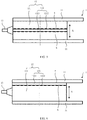
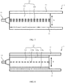
- the compensation layer 122 may be disposed in an end part of the main layer 121 of the pillar-shaped luneberg lens along an axis (namely, a direction X) of the main layer 121 of the pillar-shaped luneberg lens (as shown in FIG. 6 ), or may also be disposed in a middle part of the main layer 121 of the pillar-shaped luneberg lens along an axis (also namely, a direction X) of the main layer 121 of the pillar-shaped luneberg lens. This is not specifically limited herein. In some embodiments, as shown in FIG. 5 or FIG.
- the compensation layer 122 is disposed in the middle part of the main layer 121 of the pillar-shaped luneberg lens along the axis of the main layer 121 of the pillar-shaped luneberg lens. In this way, the compensation layer 122 can effectively compensate for the equivalent dielectric constants of the main layer 121 of the pillar-shaped luneberg lens 12 in the TE10 mode, so that the distribution of the equivalent dielectric constants of the pillar-shaped luneberg lens 12 in the TE10 mode is consistent with the distribution of the preset dielectric constants.
- the compensation layer 122 includes a sheet-like substrate 1221, the sheet-like substrate 1221 is parallel to the metal plate 11, the sheet-like substrate 1221 includes a first surface a and a second surface b that are opposite to each other, and a metal sheet array 1222 is pasted on the first surface a and/or the second surface b.
- a metamaterial layer is formed at the compensation layer 122, and the metamaterial layer can positively compensate for the equivalent dielectric constants of the main layer 121 of the pillar-shaped luneberg lens in the TE10 mode.
- the metamaterial layer has no effect on the equivalent dielectric constants of the main layer 121 of the pillar-shaped luneberg lens in the TEM mode, and can only positively compensate for the equivalent dielectric constants of the main layer 121 of the pillar-shaped luneberg lens in the TE10 mode on the premise that the distribution of the equivalent dielectric constants of the main layer 121 of the pillar-shaped luneberg lens in the TEM mode is consistent with the distribution of the preset dielectric constants, so that the distribution of the dielectric constants of the pillar-shaped luneberg lens 12 in the TE10 mode is consistent with the distribution of the preset dielectric constants.
- a plurality of metal sheets included in the metal sheet array 1222 may be first disposed on the sheet-like substrate 1221, to ensure relative position precision between the plurality of metal sheets. Then, an entirety formed by the metal sheet array 1222 and the sheet-like substrate 1221 is assembled together with the main layer 121 of the pillar-shaped luneberg lens to form the pillar-shaped luneberg lens 12.
- This manufacturing process is simple and easy to implement, and can effectively ensure the relative position precision between the plurality of metal sheets.
- there may be one compensation layer 122 or may be a plurality of compensation layers 122. This is not specifically limited herein. In some embodiments, there are a plurality of compensation layers 122, and the plurality of compensation layers 122 are pressed together to form a metal sheet array with two or more layers. A structure formed by the plurality of compensation layers 122 may be manufactured by using a multilayer circuit production technology.
- the metal sheet array 1222 may be bonded to the first surface a and/or the second surface b that are of the sheet-like substrate 1221 by using glue, or may be directly formed on the first surface a and/or the second surface b that are of the sheet-like substrate 1221. This is not specifically limited herein. In some embodiments, the metal sheet array 1222 is formed on the first surface a and/or the second surface b that are of the sheet-like substrate 1221 by using a printed circuit technology.
- the metal sheet array 1222 may be disposed only on the first surface a of the sheet-like substrate 1221, may be disposed only on the second surface b of the sheet-like substrate 1221, or may be disposed on both the first surface a and the second surface b that are of the sheet-like substrate 1221 at the same time. This is not specifically limited herein. In some embodiments, as shown in FIG. 6 , the metal sheet array 1222 may be disposed only on the second surface b of the sheet-like substrate 1221. In some other embodiments, as shown in FIG. 5 , the metal sheet array 1222 is disposed on both the first surface a and the second surface b that are of the sheet-like substrate 1221 at the same time.
- the metal sheet array 122 includes the plurality of metal sheets. Shapes of the metal sheets may include but be not limited to a circle, a square, a triangle, and a heart shape. In addition, a specific size parameter of each metal sheet, an array mode of the plurality of metal sheets, and a spacing between two adjacent metal sheets need to be determined based on a magnitude of the positive compensation of the compensation layer. In some embodiments, a shape of the metal sheet is a circle.
- the sheet-like substrate 1221 is made of an insulating material or a semiconductor material.
- the sheet-like substrate 1221 is a circuit board substrate.
- the sheet-like substrate 1221 is a circuit board substrate formed by a polytetrafluoroethylene (Polytetrafluoro ethylene, PTFE) material.
- PTFE polytetrafluoroethylene
- the compensation layer 122 includes a plurality of metal sheets arranged in a same plane, the plane in which the plurality of metal sheets are located is parallel to the metal plate 11, and each metal sheet is parallel to the metal plate 11.
- a metamaterial layer is formed at the compensation layer, and the metamaterial layer can positively compensate for the equivalent dielectric constants of the main layer 121 of the pillar-shaped luneberg lens in the TE10 mode.
- the metamaterial layer has no effect on the equivalent dielectric constants of the main layer 121 of the pillar-shaped luneberg lens in the TEM mode, and can only positively compensate for the equivalent dielectric constants of the main layer 121 of the pillar-shaped luneberg lens in the TE10 mode on the premise that the distribution of the equivalent dielectric constants of the main layer 121 of the pillar-shaped luneberg lens in the TEM mode is consistent with the distribution of the preset dielectric constants, so that the distribution of the dielectric constants of the pillar-shaped luneberg lens 12 in the TE10 mode is consistent with the distribution of the preset dielectric constants.
- the structure is simple, and an effect on a thickness of the pillar-shaped luneberg lens is relatively slight.
- the distribution of the equivalent dielectric constants of the main layer 121 of the pillar-shaped luneberg lens in the TE10 mode is consistent with the distribution of the preset dielectric constants
- the compensation layer 122 is configured to negatively compensate for the equivalent dielectric constants of the main layer 121 of the pillar-shaped luneberg lens in the TEM mode, so that the distribution of the equivalent dielectric constants of the pillar-shaped luneberg lens 12 in the TEM mode is consistent with the distribution of the preset dielectric constants.
- the pillar-shaped luneberg lens antenna 1 provided in the embodiments of this application can implement both the vertical polarization and the horizontal polarization at the same time, thereby improving the capacity of the communications system.
- the compensation layer 122 only compensates for the equivalent dielectric constants of the main layer 121 of the pillar-shaped luneberg lens in the TEM mode. Therefore, a structure of the compensation layer 122 is simple and easy to implement.
- the compensation layer 122 is a dielectric layer whose equivalent dielectric constants are less than a minimum equivalent dielectric constant of the main layer of the pillar-shaped luneberg lens, the compensation layer 122 and the main layer 121 of the pillar-shaped luneberg lens are stacked layer by layer, and the compensation layer 122 is located at at least one end of the pillar-shaped luneberg lens along an axis of the main layer 121 of the pillar-shaped luneberg lens. In this way, the compensation layer 122 can negatively compensate for the equivalent dielectric constants of the main layer 121 of the pillar-shaped luneberg lens in the TEM mode.
- the compensation layer 122 has slight effect on the equivalent dielectric constants of the main layer 121 of the pillar-shaped luneberg lens in the TE10 mode, and can only negatively compensate for the equivalent dielectric constants of the main layer 121 of the pillar-shaped luneberg lens in the TEM mode on the premise that the distribution of the equivalent dielectric constants of the main layer 121 of the pillar-shaped luneberg lens in the TE10 mode is consistent with the distribution of the preset dielectric constants, so that the distribution of the dielectric constants of the pillar-shaped luneberg lens 12 in the TEM mode is consistent with the distribution of the preset dielectric constants.
- the compensation layer 122 may be an air layer, a vacuum layer, a foam layer, a sponge layer, a puncturing medium layer, or the like. This is not specifically limited herein, provided that the equivalent dielectric constants of the compensation layer 122 are less than the minimum equivalent dielectric constant of the main layer of the pillar-shaped luneberg lens.
- the compensation layer 122 may be only an air layer, a foam layer, or a structure formed by arranging the air layer and the foam layer at intervals. This is not specifically limited herein.
- the compensation layer 122 is only an air layer.
- the compensation layer 122 is a structure formed by arranging the foam layer and the air layer at intervals.
- all equivalent dielectric constants of the main layer 121 of the pillar-shaped luneberg lens in the TEM mode along each radial position of the main layer 121 of the pillar-shaped luneberg lens are greater than dielectric constants at corresponding radii in the distribution of the preset dielectric constants.
- All equivalent dielectric constants of the main layer 121 of the pillar-shaped luneberg lens in the TE10 mode along each radial position of the main layer 121 of the pillar-shaped luneberg lens are less than dielectric constants at corresponding radii in the distribution of the preset dielectric constants.
- the compensation layer 122 is configured to negatively compensate for the equivalent dielectric constants of the main layer 121 of the pillar-shaped luneberg lens in the TEM mode, and positively compensate for the equivalent dielectric constants of the main layer 121 of the pillar-shaped luneberg lens in the TE10 mode. Therefore, the distribution of the equivalent dielectric constants of the pillar-shaped luneberg lens 12 in the TEM mode and in the TE10 mode are consistent with the distribution of the preset dielectric constants. In this way, the pillar-shaped luneberg lens antenna 1 provided in the embodiments of this application can implement both the vertical polarization and the horizontal polarization at the same time, thereby improving the capacity of the communications system.
- the compensation layer 122 includes a first compensation layer 122a and a second compensation layer 122b.
- the first compensation layer 122a is configured to negatively compensate for the equivalent dielectric constants of the main layer 121 of the pillar-shaped luneberg lens in the TEM mode, so that the distribution of the equivalent dielectric constants of the pillar-shaped luneberg lens 12 in the TEM mode is consistent with the distribution of the preset dielectric constants.
- the second compensation layer 122b is configured to positively compensate for the equivalent dielectric constants of the main layer 121 of the pillar-shaped luneberg lens in the TE10 mode, so that the distribution of the equivalent dielectric constants of the pillar-shaped luneberg lens 12 in the TE10 mode is consistent with the distribution of the preset dielectric constants.
- the pillar-shaped luneberg lens antenna 1 provided in the embodiments of this application can implement both the vertical polarization and the horizontal polarization at the same time, thereby improving the capacity of the communications system.
- the main layer 121 of the pillar-shaped luneberg lens may be in a structure of a circular flat plate, in a shape that is similar to a convex lens and that has a thin edge and a thick middle part (as shown in FIG. 10 ), or in a structure stacked by a plurality of pillar-shaped luneberg lenses 121a, 121b, and 121c (as shown in FIG. 11 ).
- the main layer 121 of the pillar-shaped luneberg lens is in a structure of a circular flat plate. In this way, a thickness of each position on the main layer 121 of the pillar-shaped luneberg lens is uniform and consistent. This makes the pillar-shaped luneberg lens more easier to process.
- the structure of the circular flat plate may be specifically the following structure.
- the main layer 121 of the pillar-shaped luneberg lens includes a plurality of annular dielectric layers 1211 that are successively disposed from inside to outside along a radial direction of the main layer 121 of the pillar-shaped luneberg lens, the plurality of annular dielectric layers 1211 are made of different materials, and dielectric constants of the materials of the plurality of annular dielectric layers 1211 gradually decrease from inside to outside along the radial direction of the main layer 121 of the pillar-shaped luneberg lens. In this way, different dielectric constants of the material are used, and the distribution of the dielectric constants of the main layer 121 of the pillar-shaped luneberg lens is simulated. This structure is simple and easy to implement.
- annular dielectric layers 1211 there may be three, five, or countless annular dielectric layers 1211. This is not specifically limited herein. In some embodiments, as shown in FIG. 12 , there are five annular dielectric layers 1211. When there are countless annular dielectric layers 1211, the main layer 121 of the pillar-shaped luneberg lens may be manufactured by using a 3D printing technology.
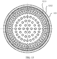
- the main layer 121 of the pillar-shaped luneberg lens includes a circular substrate 1212, a plurality of through holes 1213 are disposed on the substrate 1212, and a porosity rate of the substrate 1212 gradually increases from inside to outside along the radial direction of the main layer 121 of the pillar-shaped luneberg lens.
- a porosity mode on the substrate 1212 may be equal-spacing variable-radius porosity, or equal-radius variable-radius porosity. This is not specifically limited herein.
- the pillar-shaped luneberg lens antenna 1 further includes a dual-polarization feed 13 opposite to a side wall of the main layer 121 of the pillar-shaped luneberg lens.
- the dual-polarization feed 13 includes but is not limited to a dual-polarization microstrip patch, a dual-polarization plane Yagi antenna, a dual-polarization conical dielectric antenna, a dual-polarization open-end waveguide antenna, or a dual-polarization horn antenna.
- the pillar-shaped luneberg lens antenna 1 further includes a signal feeding apparatus (not shown in the figure).
- the signal feeding apparatus is connected to the dual-polarization feed 13.
- the signal feeding apparatus is configured to separately feed two signals whose phases differ by 90 degrees to two input ports of the dual-polarization feed 13, to implement circular polarization of the pillar-shaped luneberg lens antenna 1.
- the pillar-shaped luneberg lens antenna 1 further includes a dual-polarization feed 13 opposite to a side wall of the main layer 121 of the pillar-shaped luneberg lens.
- a dual-polarization feed 13 opposite to a side wall of the main layer 121 of the pillar-shaped luneberg lens.
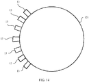
- FIG. 14 there are a plurality of dual-polarization feeds 13, and the plurality of dual-polarization feeds 13 are sequentially arranged along a circumferential direction of the main layer 121 of the pillar-shaped luneberg lens.
- a switch is switched to input signals to different dual-polarization feeds 13, and rotation scanning can be implemented in a plane parallel to the metal plate 11.
- signals can be input to the plurality of dual-polarization feeds 13 at the same time, so that a plurality of beams can work at the same time.
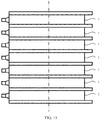
- some embodiments of this application provide a pillar-shaped luneberg lens antenna array, including a plurality of pillar-shaped luneberg lens antennas 1 according to any one of the foregoing technical solutions.
- the plurality of pillar-shaped luneberg lens antennas 1 are sequentially stacked along an extension direction of a central axis of a main layer of the pillar-shaped luneberg lens antenna 1.
- the pillar-shaped luneberg lens antenna array provided in some embodiments of this application includes the plurality of pillar-shaped luneberg lens antennas 1 according to any one of the foregoing technical solutions.
- the pillar-shaped luneberg lens antenna 1 described in any one of the foregoing technical solutions can implement the polarization in both the vertical direction and the horizontal direction at the same time, and improve the capacity of the communications system. Therefore, the pillar-shaped luneberg lens antenna array provided in the embodiments of this application can implement the polarization in both the vertical direction and the horizontal direction, and improve the capacity of the communications system.
- the pillar-shaped luneberg lens antenna array provided in the embodiments of this application can input signals with different phases to the plurality of pillar-shaped luneberg lens antennas 1, to implement beam scanning in the plane vertical to the metal plate in the pillar-shaped luneberg lens antenna 1.
Landscapes
- Engineering & Computer Science (AREA)
- Computer Networks & Wireless Communication (AREA)
- Aerials With Secondary Devices (AREA)
Applications Claiming Priority (2)
| Application Number | Priority Date | Filing Date | Title |
|---|---|---|---|
| CN201811459192.7A CN111262044B (zh) | 2018-11-30 | 2018-11-30 | 一种柱形龙伯透镜天线和柱形龙伯透镜天线阵列 |
| PCT/CN2019/121921 WO2020108607A1 (zh) | 2018-11-30 | 2019-11-29 | 一种柱形龙伯透镜天线和柱形龙伯透镜天线阵列 |
Publications (3)
| Publication Number | Publication Date |
|---|---|
| EP3876349A1 true EP3876349A1 (de) | 2021-09-08 |
| EP3876349A4 EP3876349A4 (de) | 2021-12-15 |
| EP3876349B1 EP3876349B1 (de) | 2023-10-25 |
Family
ID=70854700
Family Applications (1)
| Application Number | Title | Priority Date | Filing Date |
|---|---|---|---|
| EP19890322.1A Active EP3876349B1 (de) | 2018-11-30 | 2019-11-29 | Zylindrische antenne mit lüneburg-linse und zylindrische gruppenantenne mit lüneburg-linse |
Country Status (4)
| Country | Link |
|---|---|
| US (1) | US11757202B2 (de) |
| EP (1) | EP3876349B1 (de) |
| CN (1) | CN111262044B (de) |
| WO (1) | WO2020108607A1 (de) |
Families Citing this family (14)
| Publication number | Priority date | Publication date | Assignee | Title |
|---|---|---|---|---|
| CN112886276A (zh) * | 2021-01-14 | 2021-06-01 | 广州司南技术有限公司 | 多波束透镜天线和有源透镜天线系统 |
| CN113777778B (zh) * | 2021-08-13 | 2023-05-30 | 广东盛路通信科技股份有限公司 | 龙伯透镜及其参数计算方法、制备方法、制备装置 |
| US11870148B2 (en) * | 2021-11-11 | 2024-01-09 | Raytheon Company | Planar metal Fresnel millimeter-wave lens |
| CN114188725B (zh) * | 2021-12-03 | 2025-05-13 | 航天科工微系统技术有限公司 | 一种基于龙伯透镜的平面波发生器 |
| CN114614268B (zh) * | 2022-01-28 | 2025-07-29 | 中信科移动通信技术股份有限公司 | 龙伯透镜制作装置、制作方法及龙伯透镜 |
| CN114597668B (zh) * | 2022-02-18 | 2025-08-26 | 广东盛路通信科技股份有限公司 | 一种龙伯球装置及电调龙伯透镜天线 |
| US12592779B2 (en) | 2022-03-28 | 2026-03-31 | The United States Of America, As Represented By The Secretary Of The Navy | Near-omnidirectional optical receiver, communication system and platform |
| US11888580B2 (en) | 2022-03-28 | 2024-01-30 | United States Of America As Represented By The Secretary Of The Navy | Near-omnidirectional optical communication system |
| CN114792889B (zh) * | 2022-04-13 | 2025-08-29 | 深圳市达实智控科技股份有限公司 | 椭圆柱形龙伯透镜天线及制作方法 |
| CN114552227B (zh) * | 2022-04-27 | 2022-07-26 | 电子科技大学 | 一种基于稀布相控阵馈电的平面龙伯透镜天线 |
| CN116646736A (zh) * | 2023-06-08 | 2023-08-25 | 电子科技大学 | 一种透镜以及天线结构 |
| CN119381760A (zh) * | 2023-07-27 | 2025-01-28 | 创威讯科技股份有限公司 | 混合波束扫描的天线装置 |
| CN117913532B (zh) * | 2024-03-20 | 2024-06-04 | 微网优联科技(成都)有限公司 | 一种双极化毫米波龙勃透镜天线 |
| CN119133869B (zh) * | 2024-09-19 | 2025-12-16 | 西安电子科技大学 | 一种双圆极化3d打印多波束龙伯透镜天线 |
Family Cites Families (17)
| Publication number | Priority date | Publication date | Assignee | Title |
|---|---|---|---|---|
| US3307196A (en) * | 1962-12-28 | 1967-02-28 | Armstrong Cork Co | Luneberg type lens formed by spiral winding elongated strip of variable dielectric constant material |
| GB1166105A (en) * | 1965-10-20 | 1969-10-08 | Int Standard Electric Corp | High Gain Antenna System with 360° Coverage |
| SE420965B (sv) * | 1979-02-06 | 1981-11-09 | Philips Svenska Ab | Linsantenn |
| JP2001085936A (ja) * | 1999-09-09 | 2001-03-30 | Matsushita Electric Ind Co Ltd | 高周波基板及び誘電体レンズアンテナ、並びにその製造方法 |
| CN101872902B (zh) * | 2009-04-24 | 2013-10-30 | 电子科技大学 | 一种双极化介质杆喇叭天线馈源 |
| CN102122762B (zh) * | 2011-01-25 | 2013-08-07 | 浙江大学 | 毫米波360o全向扫描介质柱透镜天线 |
| CN102110893B (zh) * | 2011-01-25 | 2013-12-04 | 浙江大学 | 空气介质柱透镜天线 |
| JP5904490B2 (ja) * | 2012-02-15 | 2016-04-13 | 国立大学法人茨城大学 | 人工誘電体レンズ |
| CN103022727B (zh) * | 2012-12-28 | 2016-02-03 | 中国电子科技集团公司第五十四研究所 | 低剖面动中通收发共用一维有源相控阵天线 |
| US9780457B2 (en) * | 2013-09-09 | 2017-10-03 | Commscope Technologies Llc | Multi-beam antenna with modular luneburg lens and method of lens manufacture |
| CN105552572B (zh) | 2015-12-22 | 2018-03-09 | 吴锡东 | 双极化圆锥介质馈源对称介质填充柱透镜天线 |
| CN105552573B (zh) | 2015-12-22 | 2019-01-22 | 吴锡东 | 双极化波导缝隙馈源对称介质填充柱透镜天线 |
| CN105470658B (zh) | 2015-12-22 | 2019-01-22 | 吴锡东 | 双极化波导缝隙馈源非对称介质填充柱透镜天线 |
| CN105428821B (zh) * | 2015-12-22 | 2018-03-06 | 吴锡东 | 双极化圆锥介质馈源非对称介质填充柱透镜天线 |
| CN105470659A (zh) * | 2015-12-31 | 2016-04-06 | 电子科技大学 | 一种轻量化介质填充式多波束柱面龙伯透镜天线 |
| CN105470660B (zh) * | 2016-01-12 | 2018-07-27 | 电子科技大学 | 基于新型介质填充方式的极低剖面柱面龙伯透镜天线 |
| CN107275788B (zh) | 2017-07-03 | 2020-01-10 | 电子科技大学 | 一种基于金属微扰结构的毫米波扇形波束柱面龙伯透镜天线 |
-
2018
- 2018-11-30 CN CN201811459192.7A patent/CN111262044B/zh active Active
-
2019
- 2019-11-29 EP EP19890322.1A patent/EP3876349B1/de active Active
- 2019-11-29 WO PCT/CN2019/121921 patent/WO2020108607A1/zh not_active Ceased
-
2021
- 2021-05-28 US US17/334,346 patent/US11757202B2/en active Active
Also Published As
| Publication number | Publication date |
|---|---|
| WO2020108607A1 (zh) | 2020-06-04 |
| CN111262044A (zh) | 2020-06-09 |
| US20210359421A1 (en) | 2021-11-18 |
| US11757202B2 (en) | 2023-09-12 |
| EP3876349A4 (de) | 2021-12-15 |
| CN111262044B (zh) | 2021-08-13 |
| EP3876349B1 (de) | 2023-10-25 |
Similar Documents
| Publication | Publication Date | Title |
|---|---|---|
| US11757202B2 (en) | Pillar-shaped luneberg lens antenna and pillar-shaped luneberg lens antenna array | |
| US11901625B2 (en) | Antenna apparatus and electronic device | |
| US20170179596A1 (en) | Wideband reflectarray antenna for dual polarization applications | |
| US12100893B2 (en) | Antenna apparatus and electronic device | |
| US20200194898A1 (en) | Antenna system and communication terminal | |
| EP3993164A1 (de) | Antennenanordnung und elektronische vorrichtung | |
| CN114583464A (zh) | 一种三层多波束龙伯透镜天线 | |
| CN117855864A (zh) | 基于低剖面的ka波段圆极化选择性超表面单元的波束扫描天线及其波束扫描方法 | |
| CN102480036B (zh) | 基站天线 | |
| CN113471682A (zh) | 一种透镜天线 | |
| CN106229649A (zh) | 一种基于ltcc技术的基因组单元紧凑共形阵列天线 | |
| CN215896696U (zh) | 一种透镜天线 | |
| CN102593594A (zh) | 一种偏馈式卫星电视天线及其卫星电视接收系统 | |
| CN209329150U (zh) | 一种基于srr结构加载的电大微带贴片天线 | |
| CN102570044B (zh) | 基站天线 | |
| CN114050419B (zh) | 一种基于表面波双极化单元及基于该单元的龙伯透镜 | |
| EP2738872B1 (de) | Front-feed-satellitenfernsehantenne und satellitenfernsehempfängersystem dafür | |
| CN117060090A (zh) | 一种宽带圆极化平面集成馈源透射阵天线 | |
| CN117096623A (zh) | 一种用于卫星多波束通信的l波段介质透镜及透镜天线 | |
| CN103367906A (zh) | 定向传播天线罩和定向天线系统 | |
| CN102891370B (zh) | 基站天线 | |
| EP4607703A1 (de) | Antenne, elektronische vorrichtung und kommunikationsbasisstation | |
| CN102761714B (zh) | 一种卫星电视接收系统 | |
| CN114843791B (zh) | 圆柱形人工介质透镜天线及制作方法 | |
| CN116130960A (zh) | 玻璃基底超表面平面透射阵列及阵列的制造方法 |
Legal Events
| Date | Code | Title | Description |
|---|---|---|---|
| STAA | Information on the status of an ep patent application or granted ep patent |
Free format text: STATUS: THE INTERNATIONAL PUBLICATION HAS BEEN MADE |
|
| PUAI | Public reference made under article 153(3) epc to a published international application that has entered the european phase |
Free format text: ORIGINAL CODE: 0009012 |
|
| STAA | Information on the status of an ep patent application or granted ep patent |
Free format text: STATUS: REQUEST FOR EXAMINATION WAS MADE |
|
| 17P | Request for examination filed |
Effective date: 20210602 |
|
| AK | Designated contracting states |
Kind code of ref document: A1 Designated state(s): AL AT BE BG CH CY CZ DE DK EE ES FI FR GB GR HR HU IE IS IT LI LT LU LV MC MK MT NL NO PL PT RO RS SE SI SK SM TR |
|
| A4 | Supplementary search report drawn up and despatched |
Effective date: 20211117 |
|
| RIC1 | Information provided on ipc code assigned before grant |
Ipc: H01Q 21/08 20060101ALI20211111BHEP Ipc: H01Q 19/06 20060101ALI20211111BHEP Ipc: H01Q 15/08 20060101ALI20211111BHEP Ipc: H01Q 15/04 20060101ALI20211111BHEP Ipc: H01Q 3/14 20060101ALI20211111BHEP Ipc: H01Q 1/24 20060101AFI20211111BHEP |
|
| DAV | Request for validation of the european patent (deleted) | ||
| DAX | Request for extension of the european patent (deleted) | ||
| REG | Reference to a national code |
Ref country code: DE Ref legal event code: R079 Free format text: PREVIOUS MAIN CLASS: H01Q0019060000 Ipc: H01Q0001240000 Ref document number: 602019040315 Country of ref document: DE |
|
| GRAP | Despatch of communication of intention to grant a patent |
Free format text: ORIGINAL CODE: EPIDOSNIGR1 |
|
| STAA | Information on the status of an ep patent application or granted ep patent |
Free format text: STATUS: GRANT OF PATENT IS INTENDED |
|
| RIC1 | Information provided on ipc code assigned before grant |
Ipc: H01Q 21/08 20060101ALI20230512BHEP Ipc: H01Q 19/06 20060101ALI20230512BHEP Ipc: H01Q 15/08 20060101ALI20230512BHEP Ipc: H01Q 15/04 20060101ALI20230512BHEP Ipc: H01Q 3/14 20060101ALI20230512BHEP Ipc: H01Q 1/24 20060101AFI20230512BHEP |
|
| INTG | Intention to grant announced |
Effective date: 20230615 |
|
| GRAS | Grant fee paid |
Free format text: ORIGINAL CODE: EPIDOSNIGR3 |
|
| GRAA | (expected) grant |
Free format text: ORIGINAL CODE: 0009210 |
|
| STAA | Information on the status of an ep patent application or granted ep patent |
Free format text: STATUS: THE PATENT HAS BEEN GRANTED |
|
| AK | Designated contracting states |
Kind code of ref document: B1 Designated state(s): AL AT BE BG CH CY CZ DE DK EE ES FI FR GB GR HR HU IE IS IT LI LT LU LV MC MK MT NL NO PL PT RO RS SE SI SK SM TR |
|
| REG | Reference to a national code |
Ref country code: GB Ref legal event code: FG4D |
|
| REG | Reference to a national code |
Ref country code: CH Ref legal event code: EP |
|
| REG | Reference to a national code |
Ref country code: DE Ref legal event code: R096 Ref document number: 602019040315 Country of ref document: DE |
|
| REG | Reference to a national code |
Ref country code: IE Ref legal event code: FG4D |
|
| REG | Reference to a national code |
Ref country code: LT Ref legal event code: MG9D |
|
| REG | Reference to a national code |
Ref country code: NL Ref legal event code: MP Effective date: 20231025 |
|
| REG | Reference to a national code |
Ref country code: AT Ref legal event code: MK05 Ref document number: 1625621 Country of ref document: AT Kind code of ref document: T Effective date: 20231025 |
|
| PG25 | Lapsed in a contracting state [announced via postgrant information from national office to epo] |
Ref country code: NL Free format text: LAPSE BECAUSE OF FAILURE TO SUBMIT A TRANSLATION OF THE DESCRIPTION OR TO PAY THE FEE WITHIN THE PRESCRIBED TIME-LIMIT Effective date: 20231025 |
|
| PG25 | Lapsed in a contracting state [announced via postgrant information from national office to epo] |
Ref country code: GR Free format text: LAPSE BECAUSE OF FAILURE TO SUBMIT A TRANSLATION OF THE DESCRIPTION OR TO PAY THE FEE WITHIN THE PRESCRIBED TIME-LIMIT Effective date: 20240126 |
|
| PG25 | Lapsed in a contracting state [announced via postgrant information from national office to epo] |
Ref country code: IS Free format text: LAPSE BECAUSE OF FAILURE TO SUBMIT A TRANSLATION OF THE DESCRIPTION OR TO PAY THE FEE WITHIN THE PRESCRIBED TIME-LIMIT Effective date: 20240225 |
|
| PG25 | Lapsed in a contracting state [announced via postgrant information from national office to epo] |
Ref country code: LT Free format text: LAPSE BECAUSE OF FAILURE TO SUBMIT A TRANSLATION OF THE DESCRIPTION OR TO PAY THE FEE WITHIN THE PRESCRIBED TIME-LIMIT Effective date: 20231025 |
|
| PG25 | Lapsed in a contracting state [announced via postgrant information from national office to epo] |
Ref country code: AT Free format text: LAPSE BECAUSE OF FAILURE TO SUBMIT A TRANSLATION OF THE DESCRIPTION OR TO PAY THE FEE WITHIN THE PRESCRIBED TIME-LIMIT Effective date: 20231025 |
|
| PG25 | Lapsed in a contracting state [announced via postgrant information from national office to epo] |
Ref country code: ES Free format text: LAPSE BECAUSE OF FAILURE TO SUBMIT A TRANSLATION OF THE DESCRIPTION OR TO PAY THE FEE WITHIN THE PRESCRIBED TIME-LIMIT Effective date: 20231025 |
|
| PG25 | Lapsed in a contracting state [announced via postgrant information from national office to epo] |
Ref country code: LT Free format text: LAPSE BECAUSE OF FAILURE TO SUBMIT A TRANSLATION OF THE DESCRIPTION OR TO PAY THE FEE WITHIN THE PRESCRIBED TIME-LIMIT Effective date: 20231025 Ref country code: IS Free format text: LAPSE BECAUSE OF FAILURE TO SUBMIT A TRANSLATION OF THE DESCRIPTION OR TO PAY THE FEE WITHIN THE PRESCRIBED TIME-LIMIT Effective date: 20240225 Ref country code: GR Free format text: LAPSE BECAUSE OF FAILURE TO SUBMIT A TRANSLATION OF THE DESCRIPTION OR TO PAY THE FEE WITHIN THE PRESCRIBED TIME-LIMIT Effective date: 20240126 Ref country code: ES Free format text: LAPSE BECAUSE OF FAILURE TO SUBMIT A TRANSLATION OF THE DESCRIPTION OR TO PAY THE FEE WITHIN THE PRESCRIBED TIME-LIMIT Effective date: 20231025 Ref country code: BG Free format text: LAPSE BECAUSE OF FAILURE TO SUBMIT A TRANSLATION OF THE DESCRIPTION OR TO PAY THE FEE WITHIN THE PRESCRIBED TIME-LIMIT Effective date: 20240125 Ref country code: AT Free format text: LAPSE BECAUSE OF FAILURE TO SUBMIT A TRANSLATION OF THE DESCRIPTION OR TO PAY THE FEE WITHIN THE PRESCRIBED TIME-LIMIT Effective date: 20231025 Ref country code: PT Free format text: LAPSE BECAUSE OF FAILURE TO SUBMIT A TRANSLATION OF THE DESCRIPTION OR TO PAY THE FEE WITHIN THE PRESCRIBED TIME-LIMIT Effective date: 20240226 |
|
| PG25 | Lapsed in a contracting state [announced via postgrant information from national office to epo] |
Ref country code: SE Free format text: LAPSE BECAUSE OF FAILURE TO SUBMIT A TRANSLATION OF THE DESCRIPTION OR TO PAY THE FEE WITHIN THE PRESCRIBED TIME-LIMIT Effective date: 20231025 Ref country code: RS Free format text: LAPSE BECAUSE OF FAILURE TO SUBMIT A TRANSLATION OF THE DESCRIPTION OR TO PAY THE FEE WITHIN THE PRESCRIBED TIME-LIMIT Effective date: 20231025 Ref country code: PL Free format text: LAPSE BECAUSE OF FAILURE TO SUBMIT A TRANSLATION OF THE DESCRIPTION OR TO PAY THE FEE WITHIN THE PRESCRIBED TIME-LIMIT Effective date: 20231025 Ref country code: NO Free format text: LAPSE BECAUSE OF FAILURE TO SUBMIT A TRANSLATION OF THE DESCRIPTION OR TO PAY THE FEE WITHIN THE PRESCRIBED TIME-LIMIT Effective date: 20240125 Ref country code: LV Free format text: LAPSE BECAUSE OF FAILURE TO SUBMIT A TRANSLATION OF THE DESCRIPTION OR TO PAY THE FEE WITHIN THE PRESCRIBED TIME-LIMIT Effective date: 20231025 Ref country code: HR Free format text: LAPSE BECAUSE OF FAILURE TO SUBMIT A TRANSLATION OF THE DESCRIPTION OR TO PAY THE FEE WITHIN THE PRESCRIBED TIME-LIMIT Effective date: 20231025 |
|
| REG | Reference to a national code |
Ref country code: DE Ref legal event code: R119 Ref document number: 602019040315 Country of ref document: DE |
|
| REG | Reference to a national code |
Ref country code: CH Ref legal event code: PL |
|
| PG25 | Lapsed in a contracting state [announced via postgrant information from national office to epo] |
Ref country code: DK Free format text: LAPSE BECAUSE OF FAILURE TO SUBMIT A TRANSLATION OF THE DESCRIPTION OR TO PAY THE FEE WITHIN THE PRESCRIBED TIME-LIMIT Effective date: 20231025 |
|
| PG25 | Lapsed in a contracting state [announced via postgrant information from national office to epo] |
Ref country code: LU Free format text: LAPSE BECAUSE OF NON-PAYMENT OF DUE FEES Effective date: 20231129 |
|
| PG25 | Lapsed in a contracting state [announced via postgrant information from national office to epo] |
Ref country code: CH Free format text: LAPSE BECAUSE OF NON-PAYMENT OF DUE FEES Effective date: 20231130 |
|
| PG25 | Lapsed in a contracting state [announced via postgrant information from national office to epo] |
Ref country code: CZ Free format text: LAPSE BECAUSE OF FAILURE TO SUBMIT A TRANSLATION OF THE DESCRIPTION OR TO PAY THE FEE WITHIN THE PRESCRIBED TIME-LIMIT Effective date: 20231025 |
|
| PG25 | Lapsed in a contracting state [announced via postgrant information from national office to epo] |
Ref country code: SK Free format text: LAPSE BECAUSE OF FAILURE TO SUBMIT A TRANSLATION OF THE DESCRIPTION OR TO PAY THE FEE WITHIN THE PRESCRIBED TIME-LIMIT Effective date: 20231025 |
|
| PG25 | Lapsed in a contracting state [announced via postgrant information from national office to epo] |
Ref country code: SM Free format text: LAPSE BECAUSE OF FAILURE TO SUBMIT A TRANSLATION OF THE DESCRIPTION OR TO PAY THE FEE WITHIN THE PRESCRIBED TIME-LIMIT Effective date: 20231025 Ref country code: SK Free format text: LAPSE BECAUSE OF FAILURE TO SUBMIT A TRANSLATION OF THE DESCRIPTION OR TO PAY THE FEE WITHIN THE PRESCRIBED TIME-LIMIT Effective date: 20231025 Ref country code: RO Free format text: LAPSE BECAUSE OF FAILURE TO SUBMIT A TRANSLATION OF THE DESCRIPTION OR TO PAY THE FEE WITHIN THE PRESCRIBED TIME-LIMIT Effective date: 20231025 Ref country code: LU Free format text: LAPSE BECAUSE OF NON-PAYMENT OF DUE FEES Effective date: 20231129 Ref country code: IT Free format text: LAPSE BECAUSE OF FAILURE TO SUBMIT A TRANSLATION OF THE DESCRIPTION OR TO PAY THE FEE WITHIN THE PRESCRIBED TIME-LIMIT Effective date: 20231025 Ref country code: EE Free format text: LAPSE BECAUSE OF FAILURE TO SUBMIT A TRANSLATION OF THE DESCRIPTION OR TO PAY THE FEE WITHIN THE PRESCRIBED TIME-LIMIT Effective date: 20231025 Ref country code: DK Free format text: LAPSE BECAUSE OF FAILURE TO SUBMIT A TRANSLATION OF THE DESCRIPTION OR TO PAY THE FEE WITHIN THE PRESCRIBED TIME-LIMIT Effective date: 20231025 Ref country code: CZ Free format text: LAPSE BECAUSE OF FAILURE TO SUBMIT A TRANSLATION OF THE DESCRIPTION OR TO PAY THE FEE WITHIN THE PRESCRIBED TIME-LIMIT Effective date: 20231025 Ref country code: CH Free format text: LAPSE BECAUSE OF NON-PAYMENT OF DUE FEES Effective date: 20231130 |
|
| REG | Reference to a national code |
Ref country code: BE Ref legal event code: MM Effective date: 20231130 |
|
| PG25 | Lapsed in a contracting state [announced via postgrant information from national office to epo] |
Ref country code: MC Free format text: LAPSE BECAUSE OF FAILURE TO SUBMIT A TRANSLATION OF THE DESCRIPTION OR TO PAY THE FEE WITHIN THE PRESCRIBED TIME-LIMIT Effective date: 20231025 |
|
| PG25 | Lapsed in a contracting state [announced via postgrant information from national office to epo] |
Ref country code: MC Free format text: LAPSE BECAUSE OF FAILURE TO SUBMIT A TRANSLATION OF THE DESCRIPTION OR TO PAY THE FEE WITHIN THE PRESCRIBED TIME-LIMIT Effective date: 20231025 |
|
| PLBE | No opposition filed within time limit |
Free format text: ORIGINAL CODE: 0009261 |
|
| STAA | Information on the status of an ep patent application or granted ep patent |
Free format text: STATUS: NO OPPOSITION FILED WITHIN TIME LIMIT |
|
| REG | Reference to a national code |
Ref country code: IE Ref legal event code: MM4A |
|
| 26N | No opposition filed |
Effective date: 20240726 |
|
| PG25 | Lapsed in a contracting state [announced via postgrant information from national office to epo] |
Ref country code: DE Free format text: LAPSE BECAUSE OF NON-PAYMENT OF DUE FEES Effective date: 20240601 Ref country code: IE Free format text: LAPSE BECAUSE OF NON-PAYMENT OF DUE FEES Effective date: 20231129 |
|
| PG25 | Lapsed in a contracting state [announced via postgrant information from national office to epo] |
Ref country code: BE Free format text: LAPSE BECAUSE OF NON-PAYMENT OF DUE FEES Effective date: 20231130 |
|
| PG25 | Lapsed in a contracting state [announced via postgrant information from national office to epo] |
Ref country code: FR Free format text: LAPSE BECAUSE OF NON-PAYMENT OF DUE FEES Effective date: 20231225 |
|
| PG25 | Lapsed in a contracting state [announced via postgrant information from national office to epo] |
Ref country code: SI Free format text: LAPSE BECAUSE OF FAILURE TO SUBMIT A TRANSLATION OF THE DESCRIPTION OR TO PAY THE FEE WITHIN THE PRESCRIBED TIME-LIMIT Effective date: 20231025 |
|
| PG25 | Lapsed in a contracting state [announced via postgrant information from national office to epo] |
Ref country code: SI Free format text: LAPSE BECAUSE OF FAILURE TO SUBMIT A TRANSLATION OF THE DESCRIPTION OR TO PAY THE FEE WITHIN THE PRESCRIBED TIME-LIMIT Effective date: 20231025 Ref country code: IE Free format text: LAPSE BECAUSE OF NON-PAYMENT OF DUE FEES Effective date: 20231129 Ref country code: FR Free format text: LAPSE BECAUSE OF NON-PAYMENT OF DUE FEES Effective date: 20231225 Ref country code: DE Free format text: LAPSE BECAUSE OF NON-PAYMENT OF DUE FEES Effective date: 20240601 Ref country code: BE Free format text: LAPSE BECAUSE OF NON-PAYMENT OF DUE FEES Effective date: 20231130 |
|
| PG25 | Lapsed in a contracting state [announced via postgrant information from national office to epo] |
Ref country code: FI Free format text: LAPSE BECAUSE OF FAILURE TO SUBMIT A TRANSLATION OF THE DESCRIPTION OR TO PAY THE FEE WITHIN THE PRESCRIBED TIME-LIMIT Effective date: 20231025 |
|
| PG25 | Lapsed in a contracting state [announced via postgrant information from national office to epo] |
Ref country code: CY Free format text: LAPSE BECAUSE OF FAILURE TO SUBMIT A TRANSLATION OF THE DESCRIPTION OR TO PAY THE FEE WITHIN THE PRESCRIBED TIME-LIMIT; INVALID AB INITIO Effective date: 20191129 |
|
| PG25 | Lapsed in a contracting state [announced via postgrant information from national office to epo] |
Ref country code: HU Free format text: LAPSE BECAUSE OF FAILURE TO SUBMIT A TRANSLATION OF THE DESCRIPTION OR TO PAY THE FEE WITHIN THE PRESCRIBED TIME-LIMIT; INVALID AB INITIO Effective date: 20191129 |
|
| PGFP | Annual fee paid to national office [announced via postgrant information from national office to epo] |
Ref country code: GB Payment date: 20250930 Year of fee payment: 7 |
|
| PG25 | Lapsed in a contracting state [announced via postgrant information from national office to epo] |
Ref country code: TR Free format text: LAPSE BECAUSE OF FAILURE TO SUBMIT A TRANSLATION OF THE DESCRIPTION OR TO PAY THE FEE WITHIN THE PRESCRIBED TIME-LIMIT Effective date: 20231025 |