EP3876353B1 - Anschlussleiste und anschlussleistensatz - Google Patents
Anschlussleiste und anschlussleistensatz Download PDFInfo
- Publication number
- EP3876353B1 EP3876353B1 EP19895546.0A EP19895546A EP3876353B1 EP 3876353 B1 EP3876353 B1 EP 3876353B1 EP 19895546 A EP19895546 A EP 19895546A EP 3876353 B1 EP3876353 B1 EP 3876353B1
- Authority
- EP
- European Patent Office
- Prior art keywords
- terminal block
- power supply
- terminal
- side power
- wall portion
- Prior art date
- Legal status (The legal status is an assumption and is not a legal conclusion. Google has not performed a legal analysis and makes no representation as to the accuracy of the status listed.)
- Active
Links
Images



Classifications
-
- H—ELECTRICITY
- H01—ELECTRIC ELEMENTS
- H01R—ELECTRICALLY-CONDUCTIVE CONNECTIONS; STRUCTURAL ASSOCIATIONS OF A PLURALITY OF MUTUALLY-INSULATED ELECTRICAL CONNECTING ELEMENTS; COUPLING DEVICES; CURRENT COLLECTORS
- H01R9/00—Structural associations of a plurality of mutually-insulated electrical connecting elements, e.g. terminal strips or terminal blocks; Terminals or binding posts mounted upon a base or in a case; Bases therefor
- H01R9/22—Bases, e.g. strip, block, panel
- H01R9/24—Terminal blocks
- H01R9/26—Clip-on terminal blocks for side-by-side rail- or strip-mounting
-
- H—ELECTRICITY
- H01—ELECTRIC ELEMENTS
- H01R—ELECTRICALLY-CONDUCTIVE CONNECTIONS; STRUCTURAL ASSOCIATIONS OF A PLURALITY OF MUTUALLY-INSULATED ELECTRICAL CONNECTING ELEMENTS; COUPLING DEVICES; CURRENT COLLECTORS
- H01R9/00—Structural associations of a plurality of mutually-insulated electrical connecting elements, e.g. terminal strips or terminal blocks; Terminals or binding posts mounted upon a base or in a case; Bases therefor
- H01R9/22—Bases, e.g. strip, block, panel
- H01R9/24—Terminal blocks
- H01R9/2458—Electrical interconnections between terminal blocks
-
- H—ELECTRICITY
- H01—ELECTRIC ELEMENTS
- H01R—ELECTRICALLY-CONDUCTIVE CONNECTIONS; STRUCTURAL ASSOCIATIONS OF A PLURALITY OF MUTUALLY-INSULATED ELECTRICAL CONNECTING ELEMENTS; COUPLING DEVICES; CURRENT COLLECTORS
- H01R9/00—Structural associations of a plurality of mutually-insulated electrical connecting elements, e.g. terminal strips or terminal blocks; Terminals or binding posts mounted upon a base or in a case; Bases therefor
- H01R9/22—Bases, e.g. strip, block, panel
- H01R9/24—Terminal blocks
- H01R9/2408—Modular blocks
-
- H—ELECTRICITY
- H01—ELECTRIC ELEMENTS
- H01R—ELECTRICALLY-CONDUCTIVE CONNECTIONS; STRUCTURAL ASSOCIATIONS OF A PLURALITY OF MUTUALLY-INSULATED ELECTRICAL CONNECTING ELEMENTS; COUPLING DEVICES; CURRENT COLLECTORS
- H01R13/00—Details of coupling devices of the kinds covered by groups H01R12/70 or H01R24/00 - H01R33/00
- H01R13/64—Means for preventing incorrect coupling
-
- H—ELECTRICITY
- H01—ELECTRIC ELEMENTS
- H01R—ELECTRICALLY-CONDUCTIVE CONNECTIONS; STRUCTURAL ASSOCIATIONS OF A PLURALITY OF MUTUALLY-INSULATED ELECTRICAL CONNECTING ELEMENTS; COUPLING DEVICES; CURRENT COLLECTORS
- H01R4/00—Electrically-conductive connections between two or more conductive members in direct contact, i.e. touching one another; Means for effecting or maintaining such contact; Electrically-conductive connections having two or more spaced connecting locations for conductors and using contact members penetrating insulation
- H01R4/28—Clamped connections, spring connections
- H01R4/30—Clamped connections, spring connections utilising a screw or nut clamping member
Definitions
- the present disclosure relates to a terminal block that can be coupled to another terminal block in an electrically connected state and a terminal block set in which a plurality of terminal blocks are coupled in an electrically connected state.
- Patent Literature 1 discloses a terminal block in which a plurality of terminal block units are coupled.
- Patent Literature 2 discloses a module interface including a fixing device for attaching an additional module to the interface.
- a coding device is provided on the interface so that only an additional module with corresponding coding can be attached, with the coding device part of the fixing device.
- Patent Literature 3 discloses a modular terminal block for connecting leads or wires to an electrical body includes a module stack of side-by-side module assemblies and an alignment plate.
- each module assembly includes a housing, a number of conductors extending from the housing, and a cover member to cover the conductors;
- the alignment plate accurately positions the conductors despite variations in housing dimension due to manufacturing tolerances;
- the housing includes walls supported on both sides when forming part of the module stack; the walls resist deflection of the conductors during installation of the alignment plate and electrical body; and each cover member engages and is held closed by a conductor extending from the housing.
- Patent Literature 4 discloses an electrical connection device developed for quick connection via pins, wherein said device includes planar conductor portion provided with projections and urged by a spring towards a connection pad of a housing terminal. This configuration prevents the repulsion generated by a short-circuit current in a circuit breaker and maintains the contact between the conductors of the circuit breaker and the conductors connected to the differential protection unit without any screwing action.
- a positive power supply terminal of each terminal block unit when a positive power supply terminal of each terminal block unit is erroneously connected by a connecting wire in a state where the terminal block units are electrically connected, a positive power supply line may be short-circuited, and a defect such as damage or ignition of each terminal block unit may occur.
- An object of the present disclosure is to provide a terminal block capable of preventing erroneous connection of a power supply line to a power supply terminal when a plurality of terminal blocks are coupled in an electrically connected state, and a terminal block set in which a plurality of the terminal blocks are coupled.
- a terminal block of an example of the present disclosure which can be coupled to another terminal block along a first direction in an electrically connected state, the terminal block including:
- the housing includes the protruding portion that protrudes from the first wall portion in the first direction and in the direction away from the second wall portion and functions as an obstructing member that hinders connection of the input-side power supply line to the input-side power supply terminal, and the through hole that is arranged in a vicinity of the input-side power supply line of the second wall portion and penetrates the second wall portion in the first direction to allow insertion of the obstructing member.
- the terminal block can realize the terminal block set capable of preventing erroneous connection to the power supply terminal.
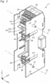
- a terminal block set 1 of an embodiment of the present disclosure includes a plurality of terminal blocks coupled along a first direction X in an electrically connected state.
- the terminal block set 1 includes, as the plurality of terminal blocks, a first terminal block 11, a second terminal block 12, and a third terminal block 13 which are electrically connected to each other.
- a direction intersecting (for example, orthogonal to) the first direction X is referred to as a second direction Y
- a direction intersecting (for example, orthogonal to) the first direction X and the second direction Y is referred to as a third direction Z.
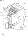
- each of the terminal blocks 11, 12, and 13 includes an insulating housing 20 and a plurality of terminals 30 arranged inside the housing 20.
- the terminal blocks 11, 12, and 13 are, for example, push-in connection type terminal blocks having substantially the same shape and size. In Fig. 2 , only the first terminal block 11 is shown.
- the housing 20 has a substantially rectangular parallelepiped shape, and includes a first wall portion 21 provided on one side in the first direction X and extending in the second direction Y, and a second wall portion 22 provided on the other side in the first direction X and extending in the second direction Y.
- the first wall portion 21 and the second wall portion 22 each have a substantially rectangular shape when viewed from the first direction X, and are arranged substantially parallel to each other at an interval in the first direction X.
- the first wall portion 21 includes a protruding portion 23 protruding from the first wall portion 21 in the first direction X and in a direction away from the second wall portion 22.
- the protruding portion 23 is formed of a substantially columnar protruding member 231, and is arranged in the vicinity of an imaginary straight line L1 (shown in Fig. 1 ) extending in the first direction X through an input-side power supply terminal 31 described later when viewed from the third direction Z.
- the protruding portion 23 is provided at one end in the longitudinal direction (that is, the upper end of Fig. 2 ) of the outer surface of the first wall portion 21.
- the second wall portion 22 has a first through hole 24 that is arranged in the vicinity of the input-side power supply terminal 31 and penetrates the second wall portion 22 in the first direction X.
- Each of the protruding portion 23 and the first through hole 24 is arranged on an imaginary straight line L2 (shown in Fig. 2 ) extending in the first direction X.
- the plurality of terminals 30 are provided at both end portions in the second direction Y (that is, in the longitudinal direction of the housing 20).
- eight terminals 30 are arranged in a lattice pattern extending in the first direction X and the second direction Y in regions at both ends of the housing 20 in the second direction Y.
- the terminals 30 include the input-side power supply terminal 31 and output-side power supply terminal 32.
- Each of the input-side power supply terminal 31 and the output-side power supply terminal 32 is arranged along the second wall portion 22 of the housing 20, and is configured to be connectable to each of an input-side power supply line 2 and an output-side power supply line 3 (both shown in Fig. 1 ).
- each of the input-side power supply terminal 31 and the output-side power supply terminal 32 is arranged along the second wall portion 22 in the region on the upper side in the second direction Y of the housing 20.
- the terminals 30 are independently accommodated in a plurality of accommodating portions (not shown) provided inside the housing 20.
- Each accommodating portion communicates with an outside of the housing 20 via two opening portions 25 and 26 opened in the third direction Z.
- One opening portion 25 is configured such that a conductor portion (not shown) of an electric wire can be inserted and removed.
- the other opening portion 26 is configured such that a long jig (for example, a flathead screwdriver) can be inserted and removed.
- a long jig for example, a flathead screwdriver
- the protruding portion 23 of the first terminal block 11 is inserted into the first through hole 24 of the second terminal block 12, and overlaps a part or an entirety of the opening portion 25 connected to the accommodating portion in which the input-side power supply terminal 31 is accommodated when viewed from the third direction Z (that is, the sheet penetration direction of Fig. 1 ).
- the protruding portion 23 functions as an obstructing member that hinders or obstructs connection of the input-side power supply line 2 of the second terminal block 12 to the input-side power supply terminal 31.
- the protruding portion 23 of the second terminal block 12 is inserted into the first through hole 24 of the third terminal block 13, and functions as an obstructing member that hinders connection of the input-side power supply line 2 of the second terminal block 12 to the input-side power supply terminal 31. That is, the first through hole 24 is configured to allow insertion of an obstructing member.
- the housing 20 includes a protrusion 27 provided on the first wall portion 21 and arranged at an interval from the protruding portion 23 in the second direction Y, and a second through hole 28 provided on the second wall portion 22 and arranged at an interval from the first through hole 24 in the second direction Y.
- the protrusion 27 is provided at the other end (that is, the lower end of Fig. 2 ) of the first wall portion 21 in the longitudinal direction
- the second through hole 28 is provided at the other end of the second wall portion 22 in the longitudinal direction.
- Each of the protrusion 27 and the second through hole 28 is arranged on an imaginary straight line L3 (shown in Fig. 2 ) extending in the first direction X.
- the protrusion 27 of the first terminal block 11 is press-fitted into the second through hole 28 of the second terminal block 12, whereby the first terminal block 11 and the second terminal block 12 are coupled to each other. Further, the protrusion 27 of the second terminal block 12 is press-fitted into the second through hole 28 of the third terminal block 13, whereby the first terminal block 11 and the second terminal block 12 are coupled to each other.
- the protruding portion 23 is configured to be press-fitted into the first through hole 24, the protruding portion 23 and the protrusion 27 constitute a pair of press-fit protrusions, and the first through hole 24 and the second through hole 28 constitute a pair of press-fit holes. That is, the protruding portion 23 also serves as a press-fit protrusion.
- the housing 20 includes a jig groove 211 extending along the third direction Z from one edge of the first wall portion 21 in the third direction Z (that is, an edge of the first wall portion 21 on the side where the opening portions 25 and 26 of the housing 20 are opened).
- the two jig grooves 211 are arranged between the protruding portion 23 and the protrusion 27 in the second direction Y and in the vicinities of the protruding portion 23 and the protrusion 27, respectively.
- each jig groove 211 includes a bottom surface 212 facing the adjacent terminal block, and is configured to allow insertion of a long jig (for example, a flathead screwdriver).
- the bottom surface 212 of each jig groove 211 is inclined so as to approach the adjacent terminal block from one edge toward the other edge in the third direction Z.
- the housing 20 includes the protruding portion 23 that protrudes from the first wall portion 21 in the first direction X and in the direction away from the second wall portion 22 and functions as an obstructing member that hinders connection of the input-side power supply line 2 to the input-side power supply terminal 31, and the through hole 24 that is arranged in the vicinity of the input-side power supply line 2 of the second wall portion 22 and penetrates the second wall portion 22 in the first direction X to allow insertion of the obstructing member.
- the protruding portion 23 of the first terminal block 11 prevents connection of the input-side power supply line 2 to the input-side power supply terminal 31 of the second terminal block 12
- the protruding portion 23 of the second terminal block 12 prevents connection of the input-side power supply line 2 to the input-side power supply terminal 31 of the third terminal block 13.
- the terminal blocks 11, 12, and 13 can realize the terminal block set 1 capable of preventing erroneous connection to the power supply terminal 31.
- the housing 20 of the first terminal block 11 includes the pair of press-fit protrusions 23 and 27 arranged at an interval in the second direction Y of the first wall portion 21, the housing 20 of the second terminal block 12 includes the pair of press-fit holes 24 and 28 provided on the second wall portion 22 and penetrating the second wall portion 22 in the first direction X, each of the pair of press-fit protrusions 23 and 27 is configured to be press-fit into each of the pair of press-fit holes 24 and 28, and one of the pair of press-fit protrusions 23 and 27 also serves as the protruding portion 23. With such a configuration, it is possible to more reliably hold the coupling between the adjacent terminal blocks 11 and 12 of the terminal block set 1.
- the housing 20 of the first terminal block 11 includes the jig groove 211 that extend along the third direction Z from one edge of the first wall portion 21 in the third direction Z intersecting the first direction X and the second direction Y, the jig groove 211 allowing insertion of a long jig.
- the jig groove 211 includes the bottom surface 212 that faces the second terminal block 12 and is inclined so as to approach the second terminal block 12 from one edge toward the other edge in the third direction Z.
- the terminal block set 1 further includes a C-shaped coupling member 40 that couple and hold the adjacent terminal blocks 11, 12, and 13.
- the terminal block set 1 includes four coupling members 40. Two coupling members 40 of the four coupling members 40 sandwich the first wall portion 21 of the housing 20 of the first terminal block 11 and the second wall portion 22 of the housing 20 of the second terminal block 12 at both ends in the second direction Y, respectively. Further, the remaining two coupling members 40 of the four coupling members 40 sandwich the first wall portion 21 of the housing 20 of the second terminal block 12 and the second wall portion 22 of the housing 20 of the third terminal block 13 at both ends in the second direction Y, respectively.
- the coupling member 40 includes a pair of plate-shaped arm portions 41 that extend such that a plate surface of the pair of arm portions 41 faces each other and is elastically deformable in a direction away from each other, and a connecting portion 42 that connects the pair of arm portions 41.
- Each arm portion 41 includes a coupling protrusion 43 provided at an end portion farther from the connecting portion 42 in an extending direction of each arm portion 41.
- the coupling protrusions 43 each have a substantially semi-cylindrical shape and protrude in a direction approaching each other.
- One of the coupling protrusions 43 is accommodated in a first accommodation hole 213 of the first terminal block 11 or the second terminal block 12 described later, and the other of the coupling protrusions 43 is accommodated in a second accommodation hole 214 of the second terminal block 12 or the third terminal block 13 described later.
- a movement of the coupling member 40 in the second direction Y is restricted by accommodating the coupling protrusions 43 in the first accommodation hole 213 and the second accommodation hole 214.
- the housing 20 of each of the terminal blocks 11, 12, and 13 includes the first accommodation hole 213 and the second accommodation hole 214 capable of accommodating the coupling protrusions 43 of the coupling members 40, and a first accommodation groove 215 and a second accommodation groove 216 that guide the coupling protrusions 43 of the coupling members 40 to each of the accommodation holes 213 and 214.
- the first accommodation groove 215 is provided on a surface of the first wall portion 21 facing the second wall portion 22, and extends from an edge of the first wall portion 21 in a direction intersecting the first direction X toward the first accommodation hole 213.
- the first accommodation groove 215 extends toward the first accommodation hole 213 along the second direction Y from a notch 217 provided at the edge of the first wall portion 21 closer to the first accommodation hole 213 in the second direction Y.
- the second accommodation groove 216 is provided on a surface of the second wall portion 22 facing the first wall portion 21, and extends from an edge of the second wall portion 22 in the direction intersecting the first direction X toward the second accommodation hole 214.
- the second accommodation groove 216 extends toward the second accommodation hole 214 along the second direction Y from a notch 218 provided at the edge of the second wall portion 22 closer to the second accommodation hole 214 in the second direction Y.
- One of the pair of arm portions 41 of the coupling member 40 is accommodated in the first accommodation groove 215, and the other of the pair of arm portions 41 of the coupling member 40 is accommodated in the second accommodation groove 216.
- a movement of the coupling member 40 in the third direction Z is restricted.
- the housing 20 of each of the terminal blocks 11, 12, and 13 includes a coupling accommodating portion 50 that accommodate the coupling member 40.
- the housing 20 of each of the terminal blocks 11, 12, and 13 includes two coupling accommodating portions 50 arranged at an interval in the second direction Y.
- Each coupling accommodating portion 50 is provided at an end portion of the housing 20 on the side where the opening portions 25 and 26 are opened in the third direction Z, and is arranged adjacent to the first wall portion 21 of the housing 20.
- Fig. 2 a state in which the coupling members 40 are accommodated in the coupling accommodating portions 50 of the first terminal block 11 is shown.
- the coupling accommodating portion 50 includes a pair of first recessed portions 51 capable of accommodating the pair of arm portions of the coupling member 40, and a second recessed portion 52 arranged between the pair of first recessed portions 51 and capable of accommodating the connecting portion 42 of the coupling member 40.
- Each of the first recessed portions 51 has a substantially rectangular parallelepiped shape and includes a substantially L-shaped opening portion 511 extending in the first direction X and the third direction Z.
- the jig groove 211 of the first wall portion 21 is connected to the opening portion 511 of each of the first recessed portions 51.
- a Groove 53 extending in a rail shape in the first direction X is provided on an inner surface of the first recessed portions 51 facing each other in the second direction Y.
- Each groove 53 has a substantially semicircular shape, and is configured to be able to accommodate the coupling protrusion 43 of each arm portion 41 of the coupling member 40.
- the second recessed portion 52 includes a recessed-portion main body 521 that accommodates the connecting portion 42 of the coupling member 40, and an inclined surface 522 extending from the recessed-portion main body 521 in a direction intersecting the arrangement direction of the pair of first recessed portions 51 (that is, the second direction Y).
- the second recessed portion 52 has two inclined surfaces 522 extending in directions away from each other from both ends of the recessed-portion main body 521 in the second direction Y.
- Each inclined surface 522 is inclined in a direction away from the bottom surface of the recessed-portion main body 521 (that is, upward in the third direction Z of Figs. 6 and 7 ) as being away from the recessed-portion main body 521.
- Each inclined surface 522 guides a long jig (for example, a flathead screwdriver) between the connecting portion 42 of the coupling member 40 and the recessed-portion main body 521, so that the coupling member 40 accommodated in the coupling accommodating portion 50 can be easily removed.
- the terminal block set 1 includes the C-shaped coupling members 40 that each sandwich, and couple and hold the first wall portion 21 of the housing 20 of the first terminal block 11 and the second wall portion 22 of the housing 20 of the second terminal block 12.
- the coupling member 40 includes the pair of plate-shaped arm portions 41 that extend such that the plate surface of the pair of arm portions faces each other and is elastically deformable in the direction away from each other.
- the connecting portion 42 that connects the pair of arm portions 41.
- Each of the arm portions 41 has the coupling protrusion 43 provided at the end portion farther from the connecting portion 42 in the extending direction and protruding in the direction approaching each other.
- Each of the first wall portion 21 of the first terminal block 11 and the second wall portion 22 of the second terminal block 12 has each of the first accommodation hole 213 and the second accommodation hole 214 in which the coupling protrusion 43 of each arm portion 41 is accommodated.
- first wall portion 21 of the first terminal block 11 has the first accommodation groove 215 that is provided on the surface facing the second wall portion 22, extends toward the first accommodation hole 213 from the edge of the first wall portion 21 in the direction intersecting the first direction X, and accommodates one of the pair of arm portions 41 of the coupling member 40.
- the second wall portion 22 of the second terminal block 12 has the second accommodation groove 216 that is provided on the surface facing the first wall portion 21, extends toward the second accommodation hole 214 from the edge of the second wall portion 22 in the direction intersecting the first direction X, and accommodates the other of the pair of arm portions 41 of the coupling member 40.
- each of the housing 20 of the first terminal block 11 and the housing 20 of the second terminal block 12 includes the coupling accommodating portion 50 that accommodate the coupling member 40.
- the coupling member 40 that is not used can be accommodated in the coupling accommodating portion 50, the loss of the coupling member 40 can be prevented.
- the coupling accommodating portion 50 includes the pair of first recessed portions 51 capable of accommodating the pair of arm portions 41, and the second recessed portion 52 arranged between the pair of first recessed portions 51 and capable of accommodating the connecting portion 42.
- the second recessed portion 52 includes the recessed-portion main body 521 that accommodates the connecting portion 42, and the inclined surface 522 that extends from the recessed-portion main body 521 along the direction intersecting the arrangement direction of the pair of first recessed portions 51 and is inclined in the direction away from the bottom surface of the recessed-portion main body 521 as being away from the recessed-portion main body 521.
- a long jig (for example, a flathead screwdriver) can be guided between the connecting portion 42 of the coupling member 40 and the recessed-portion main body 521, so that the coupling member 40 accommodated in the coupling accommodating portion 50 can be easily removed.
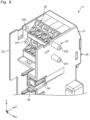
- the protruding portion 23 is not limited to a case where it is formed of one substantially columnar protruding member.
- two substantially cylindrical protruding members 231 and 232 that is, the first protruding member 231 and a second protruding member 232
- the protruding portion 23 functions as an obstructing member that hinders connection of the input-side power supply line 2 to the input-side power supply terminal 31 and hinders connection of the output-side power supply line 3 to the output-side power supply terminal 32.
- the second protruding member 232 is arranged in the vicinity of an imaginary straight line L4 (shown in Fig.
- the second wall portion 22 is provided with a substantially circular through hole 242 corresponding to the second protruding portion 232.
- the protruding members 231 and 232 may have the same shape and size, or may have different shapes and sizes.
- Each protruding member 231 is not limited to a substantially cylindrical shape, and may have a substantially prismatic shape or an elliptical shape.
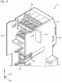
- the protruding portion 23 may be constituted by a third protruding member 233 that functions as an obstructing member that simultaneously hinders both connection of the input-side power supply line 2 to the input-side power supply terminal 31 and connection of the output-side power supply line 3 to the output-side power supply terminal 32.
- the third protruding member 233 having a substantially rectangular plate shape is shown. Both end portions of the third protruding member 233 in the second direction Y are arranged near the imaginary straight lines L1 and L3, respectively.
- the second wall portion 22 is provided with a through hole 243 having a substantially rectangular shape corresponding to the third protruding member 233.
- the protruding portion 23 only needs to function as an obstructing member that hinders at least connection of the input-side power supply line 2 to the input-side power supply terminal 31, and any shape, size, and configuration can be adopted in accordance with the design of the terminal block set 1 and the like.
- Each of the terminal blocks 11, 12, and 13 is not limited to the above embodiment, and can be optionally configured in accordance with a design of the terminal block set 1 or the like as long as it includes the housing 20 including the first wall portion 21 and the second wall portion 22, and the input-side power supply terminal 31 and the output-side power supply terminal 32 arranged inside the housing 20.
- the coupling member 40 only needs to have a C shape and be capable of sandwiching, and coupling and holding the first wall portion 21 of the terminal block (for example, first terminal block 11) and the second wall portion 22 of the terminal block (for example, second terminal block 12) adjacent to the terminal block, and can be optionally configured in accordance with the design of the terminal block set 1 or the like.
- the coupling accommodating portion 50 only needs to accommodate the coupling member 40, and can be optionally configured in accordance with the design of the terminal block set 1 or the like.
- the coupling member 40, the coupling accommodating portion 50, the accommodation holes 213 and 214, and the accommodation grooves 215 and 216 can be omitted.
- the protruding portion 23 does not need to also serve as the press-fit protrusion, and the press-fit protrusion may be separately provided.
- the protrusion 27 (that is, the press-fit protrusion), the through hole 28 (that is, the press-fitting hole), and the jig grooves 211 can be omitted.
- a terminal block 11, 12, 13 of a first aspect of the present disclosure which can be coupled to another terminal block along a first direction X in an electrically connected state, the terminal block 11, 12, 13 including:
- the housing 20 includes the protruding portion 23 that protrudes from the first wall portion 21 in the first direction X and in the direction away from the second wall portion 22 and functions as an obstructing member that hinders connection of the input-side power supply line 2 to the input-side power supply terminal 31, and the through hole 24 that is arranged in the vicinity of the input-side power supply line 2 of the second wall portion 22 and penetrates the second wall portion 22 in the first direction X to allow insertion of the obstructing member.
- the terminal block 11, 12, 13 capable of preventing erroneous connection to the power supply terminal 31 when the plurality of the terminal blocks are coupled in an electrically connected state.
- the protruding portion 23 functions as the obstructing member that hinders connection of the input-side power supply line 2 to the input-side power supply terminal 31 and hinders connection of the output-side power supply line 3 to the output-side power supply terminal 32.
- the terminal block 11, 12, 13 of the second aspect it is possible to realize the terminal block 11, 12, 13 capable of more reliably preventing erroneous connection to the power supply terminal 31 when the plurality of the terminal blocks are coupled in an electrically connected state.
- the protruding portion 23 includes:
- the terminal block 11, 12, 13 of the third aspect it is possible to realize the terminal block 11, 12, 13 capable of more reliably preventing erroneous connection to the power supply terminal 31 when the plurality of the terminal blocks are coupled in an electrically connected state.
- the protruding portion 23 includes a third protruding member 233 that functions as the obstructing member that simultaneously hinders both connection of the input-side power supply line 2 to the input-side power supply terminal 31 and connection of the output-side power supply line 3 to the output-side power supply terminal 32.
- the terminal block 11, 12, 13 of the fourth aspect it is possible to realize the terminal block 11, 12, 13 capable of more reliably preventing erroneous connection to the power supply terminal 31 when the plurality of the terminal blocks are coupled in an electrically connected state.
- a terminal block set 1 of a fifth aspect of the present disclosure in which a plurality of terminal blocks 11, 12, and 13 of the above aspect are coupled along the first direction X in an electrically connected state
- the terminal blocks 11, 12, and 13 can realize the terminal block set 1 capable of preventing erroneous connection to the power supply terminal 31.
- terminal block set 1 of the sixth aspect it is possible to more reliably hold the coupling between the adjacent terminal blocks 11, 12, and 13 of the terminal block set 1.
- the housing 20 of the first terminal block 11 has a jig groove 211 that extends along a third direction Z from a first edge (one edge) of the first wall portion 21 in the third direction Z intersecting the first direction X and the second direction Y and allows insertion of a long jig.
- the terminal block set 1 of the seventh aspect for example, by inserting a long jig into each jig groove 211 of the first terminal block 11 of the terminal block set 1, the coupling between the adjacent terminal blocks 11, 12, and 13 can be easily released.
- the jig groove 211 includes a bottom surface 212 that faces the second terminal block 12 and is inclined so as to approach the second terminal block 12 from the first edge (one edge) toward a second edge (the other edge) in the third direction Z.
- the terminal block set 1 of the eighth aspect it is possible to more easily release the coupling between the adjacent terminal blocks 11, 12, and 13 (for example, between the first terminal block 11 and the second terminal block 12 adjacent to first terminal block 11) of the terminal block set 1 using a long jig.
- the terminal blocks and the terminal block set of the present disclosure can be used for, for example, a temperature regulator of a control panel.
Landscapes
- Connections Arranged To Contact A Plurality Of Conductors (AREA)
Claims (8)
- Anschlussleiste (12), die an eine andere Anschlussleiste entlang einer ersten Richtung in einem elektrisch verbundenen Zustand gekoppelt werden kann und geeignet ist, um zwischen einer ersten und einer zweiten anderen Anschlussleiste (13, 11) in der ersten Richtung montiert zu sein, wobei die Anschlussleiste (12) Folgendes umfasst:ein Gehäuse (20), das einen ersten Wandabschnitt (21), der auf einer ersten Seite in der ersten Richtung bereitgestellt ist und sich in einer zweiten Richtung erstreckt, welche die erste Richtung schneidet, und einen zweiten Wandabschnitt (22), der auf einer zweiten Seite in der ersten Richtung bereitgestellt ist und sich in der zweiten Richtung erstreckt, beinhaltet; undeinen eingangsseitigen Stromversorgungsanschluss (31) und einen ausgangsseitigen Stromversorgungsanschluss (32), die entlang des zweiten Wandabschnittes (22) innerhalb des Gehäuses (20) angeordnet sind und jeweils mit einer eingangsseitigen Stromversorgungsleitung und einer ausgangsseitigen Stromversorgungsleitung verbunden werden können,dadurch gekennzeichnet, dass das Gehäuse (20) Folgendes beinhaltet:einen hervorstehenden Abschnitt (23), der von dem ersten Wandabschnitt (21) in der ersten Richtung und in einer Richtung weg von dem zweiten Wandabschnitt (22) hervorsteht und als Sperrelement fungiert, das Verbindung der eingangsseitigen Stromversorgungsleitung mit dem eingangsseitigen Stromversorgungsanschluss der ersten anderen Anschlussleiste (13) behindert; undein Durchgangsloch (24), das in einer Nähe des eingangsseitigen Stromversorgungsanschlusses (31) des zweiten Wandabschnittes (22) angeordnet ist und den zweiten Wandabschnitt (22) in der ersten Richtung durchdringt, um Einführung des Sperrelements der zweiten anderen Anschlussleiste (11) zu ermöglichen.
- Anschlussleiste (12) nach Anspruch 1, wobei
der hervorstehende Abschnitt (23) als Sperrelement fungiert, das Verbindung der eingangsseitigen Stromversorgungsleitung mit dem eingangsseitigen Stromversorgungsanschluss (31) behindert und Verbindung der ausgangsseitigen Stromversorgungsleitung mit dem ausgangsseitigen Stromversorgungsanschluss (32) behindert. - Anschlussleiste (12) nach Anspruch 2, wobei
der hervorstehende Abschnitt (23) Folgendes beinhaltet:ein erstes hervorstehendes Element (231), das als Sperrelement fungiert, das Verbindung der eingangsseitigen Stromversorgungsleitung mit dem eingangsseitigen Stromversorgungsanschluss (31) behindert; undein zweites hervorstehendes Element (232), das als Sperrelement fungiert, das Verbindung der ausgangsseitigen Stromversorgungsleitung mit dem ausgangsseitigen Stromversorgungsanschluss (32) behindert. - Anschlussleiste (12) nach Anspruch 2, wobei
der hervorstehende Abschnitt (23) ein drittes hervorstehendes Element (233) beinhaltet, das als Sperrelement fungiert, das gleichzeitig sowohl Verbindung der eingangsseitigen Stromversorgungsleitung mit dem eingangsseitigen Stromversorgungsanschluss (31) als auch Verbindung der ausgangsseitigen Stromversorgungsleitung mit dem ausgangsseitigen Stromversorgungsanschluss (32) behindert. - Anschlussleistensatz (1), in dem eine Vielzahl von Anschlussleisten (11, 12, 13) jeweils nach einem der Ansprüche 1 bis 4 entlang der ersten Richtung in einem elektrisch verbundenen Zustand gekoppelt ist, wobei der Anschlussleistensatz (1) Folgendes umfasst:eine erste Anschlussleiste (11) und eine zweite Anschlussleiste (12) benachbart zu der ersten Anschlussleiste (11) als die Vielzahl von Anschlussleisten, wobeider hervorstehende Abschnitt (23) der ersten Anschlussleiste (11) in das Durchgangsloch (24) der zweiten Anschlussleiste (12) eingeführt ist, um Verbindung der eingangsseitigen Stromversorgungsleitung mit dem eingangsseitigen Stromversorgungsanschluss (31) zu behindern.
- Anschlussleistensatz (1) nach Anspruch 5, wobeidas Gehäuse (20) der ersten Anschlussleiste (11) ein Paar Einpressvorsprünge (23, 27) beinhaltet, das in einem Intervall in der zweiten Richtung des ersten Wandabschnittes (21) angeordnet ist,das Gehäuse (20) der zweiten Anschlussleiste (12) ein Paar Einpresslöcher (24, 28) beinhaltet, das an dem zweiten Wandabschnitt (22) bereitgestellt ist und den zweiten Wandabschnitt (22) in der ersten Richtung durchdringt,jeder von dem Paar Einpressvorsprüngen (23, 27) konfiguriert ist, um in jedes von dem Paar Einpresslöchern (24, 28) eingepresst zu werden, undeiner von dem Paar Einpressvorsprüngen (23, 27) auch als hervorstehender Abschnitt dient.
- Anschlussleistensatz (1) nach Anspruch 5 oder 6, wobei
das Gehäuse (20) der ersten Anschlussleiste (11) eine Vorrichtungsnut (211) beinhaltet, die sich entlang einer dritten Richtung von einer ersten Kante des ersten Wandabschnittes (21) in der dritten Richtung erstreckt, welche die erste Richtung und die zweite Richtung schneidet und Einführung einer langen Vorrichtung ermöglicht. - Anschlussleistensatz (1) nach Anspruch 7, wobei
die Vorrichtungsnut (211) eine Bodenfläche (212) beinhaltet, die der zweiten Anschlussleiste (12) zugewandt ist und geneigt ist, um sich der zweiten Anschlussleiste (12) von der ersten Kante zu einer zweiten Kante in der dritten Richtung zu nähern.
Applications Claiming Priority (2)
| Application Number | Priority Date | Filing Date | Title |
|---|---|---|---|
| JP2018234668A JP6962309B2 (ja) | 2018-12-14 | 2018-12-14 | 端子台および端子台セット |
| PCT/JP2019/047839 WO2020121970A1 (ja) | 2018-12-14 | 2019-12-06 | 端子台および端子台セット |
Publications (3)
| Publication Number | Publication Date |
|---|---|
| EP3876353A1 EP3876353A1 (de) | 2021-09-08 |
| EP3876353A4 EP3876353A4 (de) | 2022-08-03 |
| EP3876353B1 true EP3876353B1 (de) | 2024-11-20 |
Family
ID=71076879
Family Applications (1)
| Application Number | Title | Priority Date | Filing Date |
|---|---|---|---|
| EP19895546.0A Active EP3876353B1 (de) | 2018-12-14 | 2019-12-06 | Anschlussleiste und anschlussleistensatz |
Country Status (6)
| Country | Link |
|---|---|
| US (1) | US11870200B2 (de) |
| EP (1) | EP3876353B1 (de) |
| JP (1) | JP6962309B2 (de) |
| KR (1) | KR102629371B1 (de) |
| CN (1) | CN113169468B (de) |
| WO (1) | WO2020121970A1 (de) |
Families Citing this family (3)
| Publication number | Priority date | Publication date | Assignee | Title |
|---|---|---|---|---|
| JP7501327B2 (ja) * | 2020-11-27 | 2024-06-18 | オムロン株式会社 | 端子台 |
| EP4114156B1 (de) * | 2021-06-29 | 2025-08-06 | Abb Schweiz Ag | Anschlussblockeinheit für eine eingang/ausgang-vorrichtung eines modularen prozesssteuerungssystems |
| KR102699516B1 (ko) * | 2022-08-03 | 2024-08-30 | 주식회사 에니트 | 분리형 분산 제어 시스템 |
Family Cites Families (21)
| Publication number | Priority date | Publication date | Assignee | Title |
|---|---|---|---|---|
| JPH05290906A (ja) * | 1992-04-14 | 1993-11-05 | Toshiba Corp | 連結式ソケット端子台 |
| DE4402002B4 (de) * | 1994-01-18 | 2005-10-27 | Wago Verwaltungsgesellschaft Mbh | E/A-Module/ für einen Datenbus |
| JP2000231950A (ja) | 1999-02-12 | 2000-08-22 | Nitto Electric Works Ltd | 端子台 |
| US6425770B1 (en) * | 2000-04-14 | 2002-07-30 | Rockwell Automation Technologies, Inc. | Input/output device having removable module |
| US6629852B2 (en) * | 2001-03-15 | 2003-10-07 | Omron Corporation | Relay socket |
| JP2004327258A (ja) * | 2003-04-25 | 2004-11-18 | Mitsubishi Electric Corp | 機器装着用ソケット装置 |
| US6811425B1 (en) * | 2003-09-25 | 2004-11-02 | Excel Cell Electronic Co., Ltd. | Controller module responsive to input signals for controlling an electrical appliance |
| EP1564848B1 (de) * | 2004-02-16 | 2013-10-16 | Siemens Aktiengesellschaft | Installationsgerät mit kodierbarer Steckschnittstelle und entsprechendes Zusatzmodul |
| US7576630B2 (en) * | 2004-09-13 | 2009-08-18 | Cooper Technologies Company | Fusible switching disconnect modules and devices |
| DE202005014718U1 (de) * | 2005-09-17 | 2007-02-01 | Weidmüller Interface GmbH & Co. KG | Anschluß-System zur Realisierung von Abzweigungen an durchgehenden Leitern |
| DE102007033942B4 (de) | 2007-07-19 | 2009-08-27 | Phoenix Contact Gmbh & Co. Kg | Elektrische Klemme |
| US7553199B2 (en) | 2007-07-31 | 2009-06-30 | Phoenix Contact Development & Manufacturing, Inc. | Modular terminal block |
| DE102008033430B4 (de) * | 2008-07-16 | 2010-04-01 | Adc Gmbh | Verteileranschlussmodul für die Telekommunikations- und Datentechnik |
| FR2937188A1 (fr) * | 2008-10-09 | 2010-04-16 | Schneider Electric Ind Sas | Dispositif et ensemble coulissant de connexion electrique, en particulier pour bloc de protection differentielle |
| US9024486B2 (en) * | 2010-08-20 | 2015-05-05 | Rockwell Automation Technologies, Inc. | Adaptable automation control module with integrated power bus distributor |
| US9055687B2 (en) * | 2010-08-20 | 2015-06-09 | Rockwell Automation Technologies, Inc. | Input/output circuits and devices having physically corresponding status indicators |
| JP5474267B1 (ja) * | 2013-04-25 | 2014-04-16 | 三菱電機株式会社 | レセプタクル保護カバー及び電子機器 |
| JP6308439B2 (ja) * | 2015-02-10 | 2018-04-11 | 株式会社オートネットワーク技術研究所 | 電源分配装置 |
| JP6784483B2 (ja) | 2015-07-24 | 2020-11-11 | 東朋テクノロジー株式会社 | センサー用端子台および端子台ユニット |
| JP1590384S (de) * | 2017-02-14 | 2017-11-13 | ||
| JP7001047B2 (ja) * | 2018-12-14 | 2022-01-19 | オムロン株式会社 | 端子台 |
-
2018
- 2018-12-14 JP JP2018234668A patent/JP6962309B2/ja active Active
-
2019
- 2019-12-06 WO PCT/JP2019/047839 patent/WO2020121970A1/ja not_active Ceased
- 2019-12-06 CN CN201980079389.4A patent/CN113169468B/zh active Active
- 2019-12-06 US US17/312,731 patent/US11870200B2/en active Active
- 2019-12-06 EP EP19895546.0A patent/EP3876353B1/de active Active
- 2019-12-06 KR KR1020217015542A patent/KR102629371B1/ko active Active
Also Published As
| Publication number | Publication date |
|---|---|
| JP2020095914A (ja) | 2020-06-18 |
| CN113169468A (zh) | 2021-07-23 |
| US11870200B2 (en) | 2024-01-09 |
| WO2020121970A1 (ja) | 2020-06-18 |
| US20220021134A1 (en) | 2022-01-20 |
| KR102629371B1 (ko) | 2024-01-29 |
| JP6962309B2 (ja) | 2021-11-05 |
| EP3876353A4 (de) | 2022-08-03 |
| CN113169468B (zh) | 2023-05-23 |
| KR20210076137A (ko) | 2021-06-23 |
| EP3876353A1 (de) | 2021-09-08 |
Similar Documents
| Publication | Publication Date | Title |
|---|---|---|
| EP2418742B1 (de) | Fingerschutz für 90°-Verbinder | |
| CN107895872B (zh) | 汇流条头座组件 | |
| CN105103377B (zh) | 插接装置 | |
| JP2017069133A (ja) | コネクタ | |
| EP3876353B1 (de) | Anschlussleiste und anschlussleistensatz | |
| CN110277659B (zh) | 连接件以及插座 | |
| US7762833B2 (en) | Contact element for a plug-type connector for printed circuit boards | |
| US20080305674A1 (en) | Wire connection module | |
| RU2608761C2 (ru) | Электрический соединительный элемент | |
| US20170117675A1 (en) | Electric connector | |
| KR20160089388A (ko) | 플러그 커넥터 접촉 캐리어 | |
| US20080305661A1 (en) | Grounding comb, in particular for a plug-type connector for printed circuit boards | |
| US20160020050A1 (en) | Electronic component assembly structure and electronic component | |
| US8507809B2 (en) | Component-equipped-holder mounting structure | |
| US12142863B2 (en) | Branch connector having shorting plate connected to a pair of terminal fittings | |
| US12074405B2 (en) | Terminal block set including terminal blocks connected to each other | |
| CN105849978A (zh) | 测试电缆和用于测试电缆的插座适配器 | |
| EP3940736B1 (de) | Anschlussleiste | |
| JP5564678B2 (ja) | コネクタ、スタック状電極への接続構造 | |
| US10741964B2 (en) | Joint connector with short circuit members shorting selected tabs | |
| KR102695676B1 (ko) | 기판 커넥터 | |
| US20250164704A1 (en) | Connector system for optical fibres and assembly device | |
| KR101335104B1 (ko) | 커넥터 유니트 | |
| EP3182518B1 (de) | Elektrischer steckverbinder | |
| CN116365272A (zh) | 模块化电路板装置和安装电路板装置的方法 |
Legal Events
| Date | Code | Title | Description |
|---|---|---|---|
| STAA | Information on the status of an ep patent application or granted ep patent |
Free format text: STATUS: THE INTERNATIONAL PUBLICATION HAS BEEN MADE |
|
| PUAI | Public reference made under article 153(3) epc to a published international application that has entered the european phase |
Free format text: ORIGINAL CODE: 0009012 |
|
| STAA | Information on the status of an ep patent application or granted ep patent |
Free format text: STATUS: REQUEST FOR EXAMINATION WAS MADE |
|
| 17P | Request for examination filed |
Effective date: 20210602 |
|
| AK | Designated contracting states |
Kind code of ref document: A1 Designated state(s): AL AT BE BG CH CY CZ DE DK EE ES FI FR GB GR HR HU IE IS IT LI LT LU LV MC MK MT NL NO PL PT RO RS SE SI SK SM TR |
|
| DAV | Request for validation of the european patent (deleted) | ||
| DAX | Request for extension of the european patent (deleted) | ||
| A4 | Supplementary search report drawn up and despatched |
Effective date: 20220630 |
|
| RIC1 | Information provided on ipc code assigned before grant |
Ipc: H01R 13/64 20060101ALN20220624BHEP Ipc: H01R 4/30 20060101ALN20220624BHEP Ipc: H01R 9/26 20060101AFI20220624BHEP |
|
| REG | Reference to a national code |
Ref country code: DE Ref legal event code: R079 Free format text: PREVIOUS MAIN CLASS: H01R0009240000 Ipc: H01R0009260000 Ref document number: 602019062401 Country of ref document: DE |
|
| RIC1 | Information provided on ipc code assigned before grant |
Ipc: H01R 13/64 20060101ALN20240711BHEP Ipc: H01R 4/30 20060101ALN20240711BHEP Ipc: H01R 9/26 20060101AFI20240711BHEP |
|
| GRAP | Despatch of communication of intention to grant a patent |
Free format text: ORIGINAL CODE: EPIDOSNIGR1 |
|
| STAA | Information on the status of an ep patent application or granted ep patent |
Free format text: STATUS: GRANT OF PATENT IS INTENDED |
|
| RIC1 | Information provided on ipc code assigned before grant |
Ipc: H01R 13/64 20060101ALN20240805BHEP Ipc: H01R 4/30 20060101ALN20240805BHEP Ipc: H01R 9/26 20060101AFI20240805BHEP |
|
| RIC1 | Information provided on ipc code assigned before grant |
Ipc: H01R 13/64 20060101ALN20240828BHEP Ipc: H01R 4/30 20060101ALN20240828BHEP Ipc: H01R 9/26 20060101AFI20240828BHEP |
|
| INTG | Intention to grant announced |
Effective date: 20240905 |
|
| GRAS | Grant fee paid |
Free format text: ORIGINAL CODE: EPIDOSNIGR3 |
|
| GRAA | (expected) grant |
Free format text: ORIGINAL CODE: 0009210 |
|
| STAA | Information on the status of an ep patent application or granted ep patent |
Free format text: STATUS: THE PATENT HAS BEEN GRANTED |
|
| AK | Designated contracting states |
Kind code of ref document: B1 Designated state(s): AL AT BE BG CH CY CZ DE DK EE ES FI FR GB GR HR HU IE IS IT LI LT LU LV MC MK MT NL NO PL PT RO RS SE SI SK SM TR |
|
| REG | Reference to a national code |
Ref country code: GB Ref legal event code: FG4D |
|
| REG | Reference to a national code |
Ref country code: CH Ref legal event code: EP |
|
| REG | Reference to a national code |
Ref country code: DE Ref legal event code: R096 Ref document number: 602019062401 Country of ref document: DE |
|
| REG | Reference to a national code |
Ref country code: IE Ref legal event code: FG4D |
|
| REG | Reference to a national code |
Ref country code: LT Ref legal event code: MG9D |
|
| REG | Reference to a national code |
Ref country code: NL Ref legal event code: MP Effective date: 20241120 |
|
| PG25 | Lapsed in a contracting state [announced via postgrant information from national office to epo] |
Ref country code: PT Free format text: LAPSE BECAUSE OF FAILURE TO SUBMIT A TRANSLATION OF THE DESCRIPTION OR TO PAY THE FEE WITHIN THE PRESCRIBED TIME-LIMIT Effective date: 20250320 Ref country code: HR Free format text: LAPSE BECAUSE OF FAILURE TO SUBMIT A TRANSLATION OF THE DESCRIPTION OR TO PAY THE FEE WITHIN THE PRESCRIBED TIME-LIMIT Effective date: 20241120 Ref country code: IS Free format text: LAPSE BECAUSE OF FAILURE TO SUBMIT A TRANSLATION OF THE DESCRIPTION OR TO PAY THE FEE WITHIN THE PRESCRIBED TIME-LIMIT Effective date: 20250320 |
|
| PG25 | Lapsed in a contracting state [announced via postgrant information from national office to epo] |
Ref country code: FI Free format text: LAPSE BECAUSE OF FAILURE TO SUBMIT A TRANSLATION OF THE DESCRIPTION OR TO PAY THE FEE WITHIN THE PRESCRIBED TIME-LIMIT Effective date: 20241120 Ref country code: NL Free format text: LAPSE BECAUSE OF FAILURE TO SUBMIT A TRANSLATION OF THE DESCRIPTION OR TO PAY THE FEE WITHIN THE PRESCRIBED TIME-LIMIT Effective date: 20241120 |
|
| REG | Reference to a national code |
Ref country code: AT Ref legal event code: MK05 Ref document number: 1744448 Country of ref document: AT Kind code of ref document: T Effective date: 20241120 |
|
| PG25 | Lapsed in a contracting state [announced via postgrant information from national office to epo] |
Ref country code: BG Free format text: LAPSE BECAUSE OF FAILURE TO SUBMIT A TRANSLATION OF THE DESCRIPTION OR TO PAY THE FEE WITHIN THE PRESCRIBED TIME-LIMIT Effective date: 20241120 |
|
| PG25 | Lapsed in a contracting state [announced via postgrant information from national office to epo] |
Ref country code: ES Free format text: LAPSE BECAUSE OF FAILURE TO SUBMIT A TRANSLATION OF THE DESCRIPTION OR TO PAY THE FEE WITHIN THE PRESCRIBED TIME-LIMIT Effective date: 20241120 |
|
| PG25 | Lapsed in a contracting state [announced via postgrant information from national office to epo] |
Ref country code: NO Free format text: LAPSE BECAUSE OF FAILURE TO SUBMIT A TRANSLATION OF THE DESCRIPTION OR TO PAY THE FEE WITHIN THE PRESCRIBED TIME-LIMIT Effective date: 20250220 |
|
| PG25 | Lapsed in a contracting state [announced via postgrant information from national office to epo] |
Ref country code: AT Free format text: LAPSE BECAUSE OF FAILURE TO SUBMIT A TRANSLATION OF THE DESCRIPTION OR TO PAY THE FEE WITHIN THE PRESCRIBED TIME-LIMIT Effective date: 20241120 Ref country code: LV Free format text: LAPSE BECAUSE OF FAILURE TO SUBMIT A TRANSLATION OF THE DESCRIPTION OR TO PAY THE FEE WITHIN THE PRESCRIBED TIME-LIMIT Effective date: 20241120 Ref country code: GR Free format text: LAPSE BECAUSE OF FAILURE TO SUBMIT A TRANSLATION OF THE DESCRIPTION OR TO PAY THE FEE WITHIN THE PRESCRIBED TIME-LIMIT Effective date: 20250221 |
|
| PG25 | Lapsed in a contracting state [announced via postgrant information from national office to epo] |
Ref country code: PL Free format text: LAPSE BECAUSE OF FAILURE TO SUBMIT A TRANSLATION OF THE DESCRIPTION OR TO PAY THE FEE WITHIN THE PRESCRIBED TIME-LIMIT Effective date: 20241120 |
|
| PG25 | Lapsed in a contracting state [announced via postgrant information from national office to epo] |
Ref country code: RS Free format text: LAPSE BECAUSE OF FAILURE TO SUBMIT A TRANSLATION OF THE DESCRIPTION OR TO PAY THE FEE WITHIN THE PRESCRIBED TIME-LIMIT Effective date: 20250220 |
|
| PG25 | Lapsed in a contracting state [announced via postgrant information from national office to epo] |
Ref country code: SM Free format text: LAPSE BECAUSE OF FAILURE TO SUBMIT A TRANSLATION OF THE DESCRIPTION OR TO PAY THE FEE WITHIN THE PRESCRIBED TIME-LIMIT Effective date: 20241120 |
|
| PG25 | Lapsed in a contracting state [announced via postgrant information from national office to epo] |
Ref country code: DK Free format text: LAPSE BECAUSE OF FAILURE TO SUBMIT A TRANSLATION OF THE DESCRIPTION OR TO PAY THE FEE WITHIN THE PRESCRIBED TIME-LIMIT Effective date: 20241120 |
|
| PG25 | Lapsed in a contracting state [announced via postgrant information from national office to epo] |
Ref country code: EE Free format text: LAPSE BECAUSE OF FAILURE TO SUBMIT A TRANSLATION OF THE DESCRIPTION OR TO PAY THE FEE WITHIN THE PRESCRIBED TIME-LIMIT Effective date: 20241120 |
|
| PG25 | Lapsed in a contracting state [announced via postgrant information from national office to epo] |
Ref country code: RO Free format text: LAPSE BECAUSE OF FAILURE TO SUBMIT A TRANSLATION OF THE DESCRIPTION OR TO PAY THE FEE WITHIN THE PRESCRIBED TIME-LIMIT Effective date: 20241120 |
|
| PG25 | Lapsed in a contracting state [announced via postgrant information from national office to epo] |
Ref country code: SK Free format text: LAPSE BECAUSE OF FAILURE TO SUBMIT A TRANSLATION OF THE DESCRIPTION OR TO PAY THE FEE WITHIN THE PRESCRIBED TIME-LIMIT Effective date: 20241120 |
|
| PG25 | Lapsed in a contracting state [announced via postgrant information from national office to epo] |
Ref country code: CZ Free format text: LAPSE BECAUSE OF FAILURE TO SUBMIT A TRANSLATION OF THE DESCRIPTION OR TO PAY THE FEE WITHIN THE PRESCRIBED TIME-LIMIT Effective date: 20241120 |
|
| REG | Reference to a national code |
Ref country code: CH Ref legal event code: PL |
|
| PG25 | Lapsed in a contracting state [announced via postgrant information from national office to epo] |
Ref country code: LU Free format text: LAPSE BECAUSE OF NON-PAYMENT OF DUE FEES Effective date: 20241206 |
|
| REG | Reference to a national code |
Ref country code: DE Ref legal event code: R097 Ref document number: 602019062401 Country of ref document: DE |
|
| PG25 | Lapsed in a contracting state [announced via postgrant information from national office to epo] |
Ref country code: SE Free format text: LAPSE BECAUSE OF FAILURE TO SUBMIT A TRANSLATION OF THE DESCRIPTION OR TO PAY THE FEE WITHIN THE PRESCRIBED TIME-LIMIT Effective date: 20241120 |
|
| PG25 | Lapsed in a contracting state [announced via postgrant information from national office to epo] |
Ref country code: MC Free format text: LAPSE BECAUSE OF FAILURE TO SUBMIT A TRANSLATION OF THE DESCRIPTION OR TO PAY THE FEE WITHIN THE PRESCRIBED TIME-LIMIT Effective date: 20241120 |
|
| PLBE | No opposition filed within time limit |
Free format text: ORIGINAL CODE: 0009261 |
|
| STAA | Information on the status of an ep patent application or granted ep patent |
Free format text: STATUS: NO OPPOSITION FILED WITHIN TIME LIMIT |
|
| REG | Reference to a national code |
Ref country code: BE Ref legal event code: MM Effective date: 20241231 |
|
| PG25 | Lapsed in a contracting state [announced via postgrant information from national office to epo] |
Ref country code: BE Free format text: LAPSE BECAUSE OF NON-PAYMENT OF DUE FEES Effective date: 20241231 |
|
| PG25 | Lapsed in a contracting state [announced via postgrant information from national office to epo] |
Ref country code: CH Free format text: LAPSE BECAUSE OF NON-PAYMENT OF DUE FEES Effective date: 20241231 |
|
| 26N | No opposition filed |
Effective date: 20250821 |
|
| PG25 | Lapsed in a contracting state [announced via postgrant information from national office to epo] |
Ref country code: IE Free format text: LAPSE BECAUSE OF NON-PAYMENT OF DUE FEES Effective date: 20241206 |
|
| GBPC | Gb: european patent ceased through non-payment of renewal fee |
Effective date: 20250220 |
|
| PG25 | Lapsed in a contracting state [announced via postgrant information from national office to epo] |
Ref country code: GB Free format text: LAPSE BECAUSE OF NON-PAYMENT OF DUE FEES Effective date: 20250220 |
|
| PGFP | Annual fee paid to national office [announced via postgrant information from national office to epo] |
Ref country code: IT Payment date: 20251203 Year of fee payment: 7 |
|
| PGFP | Annual fee paid to national office [announced via postgrant information from national office to epo] |
Ref country code: FR Payment date: 20251205 Year of fee payment: 7 |
|
| PG25 | Lapsed in a contracting state [announced via postgrant information from national office to epo] |
Ref country code: CY Free format text: LAPSE BECAUSE OF FAILURE TO SUBMIT A TRANSLATION OF THE DESCRIPTION OR TO PAY THE FEE WITHIN THE PRESCRIBED TIME-LIMIT; INVALID AB INITIO Effective date: 20191206 |
|
| PGFP | Annual fee paid to national office [announced via postgrant information from national office to epo] |
Ref country code: DE Payment date: 20251222 Year of fee payment: 7 |