EP3876855B1 - Vorrichtung zur erkennung und beseitigung von lichtbögen und lichtbogeninduziertem plasma während der energieabgabe in gewebe - Google Patents
Vorrichtung zur erkennung und beseitigung von lichtbögen und lichtbogeninduziertem plasma während der energieabgabe in gewebe Download PDFInfo
- Publication number
- EP3876855B1 EP3876855B1 EP19836013.3A EP19836013A EP3876855B1 EP 3876855 B1 EP3876855 B1 EP 3876855B1 EP 19836013 A EP19836013 A EP 19836013A EP 3876855 B1 EP3876855 B1 EP 3876855B1
- Authority
- EP
- European Patent Office
- Prior art keywords
- pulse
- pfa
- control unit
- rise
- voltage
- Prior art date
- Legal status (The legal status is an assumption and is not a legal conclusion. Google has not performed a legal analysis and makes no representation as to the accuracy of the status listed.)
- Active
Links
Images


Classifications
-
- A—HUMAN NECESSITIES
- A61—MEDICAL OR VETERINARY SCIENCE; HYGIENE
- A61B—DIAGNOSIS; SURGERY; IDENTIFICATION
- A61B18/00—Surgical instruments, devices or methods for transferring non-mechanical forms of energy to or from the body
- A61B18/04—Surgical instruments, devices or methods for transferring non-mechanical forms of energy to or from the body by heating
- A61B18/12—Surgical instruments, devices or methods for transferring non-mechanical forms of energy to or from the body by heating by passing a current through the tissue to be heated, e.g. high-frequency current
- A61B18/1206—Generators therefor
-
- A—HUMAN NECESSITIES
- A61—MEDICAL OR VETERINARY SCIENCE; HYGIENE
- A61N—ELECTROTHERAPY; MAGNETOTHERAPY; RADIATION THERAPY; ULTRASOUND THERAPY
- A61N1/00—Electrotherapy; Circuits therefor
- A61N1/18—Applying electric currents by contact electrodes
- A61N1/32—Applying electric currents by contact electrodes alternating or intermittent currents
- A61N1/327—Applying electric currents by contact electrodes alternating or intermittent currents for enhancing the absorption properties of tissue, e.g. by electroporation
-
- A—HUMAN NECESSITIES
- A61—MEDICAL OR VETERINARY SCIENCE; HYGIENE
- A61B—DIAGNOSIS; SURGERY; IDENTIFICATION
- A61B18/00—Surgical instruments, devices or methods for transferring non-mechanical forms of energy to or from the body
- A61B18/04—Surgical instruments, devices or methods for transferring non-mechanical forms of energy to or from the body by heating
- A61B18/12—Surgical instruments, devices or methods for transferring non-mechanical forms of energy to or from the body by heating by passing a current through the tissue to be heated, e.g. high-frequency current
- A61B18/1206—Generators therefor
- A61B18/1233—Generators therefor with circuits for assuring patient safety
-
- A—HUMAN NECESSITIES
- A61—MEDICAL OR VETERINARY SCIENCE; HYGIENE
- A61B—DIAGNOSIS; SURGERY; IDENTIFICATION
- A61B18/00—Surgical instruments, devices or methods for transferring non-mechanical forms of energy to or from the body
- A61B18/04—Surgical instruments, devices or methods for transferring non-mechanical forms of energy to or from the body by heating
- A61B18/12—Surgical instruments, devices or methods for transferring non-mechanical forms of energy to or from the body by heating by passing a current through the tissue to be heated, e.g. high-frequency current
- A61B18/14—Probes or electrodes therefor
- A61B18/1492—Probes or electrodes therefor having a flexible, catheter-like structure, e.g. for heart ablation
-
- A—HUMAN NECESSITIES
- A61—MEDICAL OR VETERINARY SCIENCE; HYGIENE
- A61B—DIAGNOSIS; SURGERY; IDENTIFICATION
- A61B18/00—Surgical instruments, devices or methods for transferring non-mechanical forms of energy to or from the body
- A61B2018/00315—Surgical instruments, devices or methods for transferring non-mechanical forms of energy to or from the body for treatment of particular body parts
- A61B2018/00345—Vascular system
- A61B2018/00351—Heart
-
- A—HUMAN NECESSITIES
- A61—MEDICAL OR VETERINARY SCIENCE; HYGIENE
- A61B—DIAGNOSIS; SURGERY; IDENTIFICATION
- A61B18/00—Surgical instruments, devices or methods for transferring non-mechanical forms of energy to or from the body
- A61B2018/00571—Surgical instruments, devices or methods for transferring non-mechanical forms of energy to or from the body for achieving a particular surgical effect
- A61B2018/00577—Ablation
-
- A—HUMAN NECESSITIES
- A61—MEDICAL OR VETERINARY SCIENCE; HYGIENE
- A61B—DIAGNOSIS; SURGERY; IDENTIFICATION
- A61B18/00—Surgical instruments, devices or methods for transferring non-mechanical forms of energy to or from the body
- A61B2018/00571—Surgical instruments, devices or methods for transferring non-mechanical forms of energy to or from the body for achieving a particular surgical effect
- A61B2018/00613—Irreversible electroporation
-
- A—HUMAN NECESSITIES
- A61—MEDICAL OR VETERINARY SCIENCE; HYGIENE
- A61B—DIAGNOSIS; SURGERY; IDENTIFICATION
- A61B18/00—Surgical instruments, devices or methods for transferring non-mechanical forms of energy to or from the body
- A61B2018/00636—Sensing and controlling the application of energy
- A61B2018/00642—Sensing and controlling the application of energy with feedback, i.e. closed loop control
- A61B2018/00648—Sensing and controlling the application of energy with feedback, i.e. closed loop control using more than one sensed parameter
-
- A—HUMAN NECESSITIES
- A61—MEDICAL OR VETERINARY SCIENCE; HYGIENE
- A61B—DIAGNOSIS; SURGERY; IDENTIFICATION
- A61B18/00—Surgical instruments, devices or methods for transferring non-mechanical forms of energy to or from the body
- A61B2018/00636—Sensing and controlling the application of energy
- A61B2018/00666—Sensing and controlling the application of energy using a threshold value
- A61B2018/00678—Sensing and controlling the application of energy using a threshold value upper
-
- A—HUMAN NECESSITIES
- A61—MEDICAL OR VETERINARY SCIENCE; HYGIENE
- A61B—DIAGNOSIS; SURGERY; IDENTIFICATION
- A61B18/00—Surgical instruments, devices or methods for transferring non-mechanical forms of energy to or from the body
- A61B2018/00636—Sensing and controlling the application of energy
- A61B2018/00696—Controlled or regulated parameters
- A61B2018/0072—Current
-
- A—HUMAN NECESSITIES
- A61—MEDICAL OR VETERINARY SCIENCE; HYGIENE
- A61B—DIAGNOSIS; SURGERY; IDENTIFICATION
- A61B18/00—Surgical instruments, devices or methods for transferring non-mechanical forms of energy to or from the body
- A61B2018/00636—Sensing and controlling the application of energy
- A61B2018/00696—Controlled or regulated parameters
- A61B2018/00767—Voltage
-
- A—HUMAN NECESSITIES
- A61—MEDICAL OR VETERINARY SCIENCE; HYGIENE
- A61B—DIAGNOSIS; SURGERY; IDENTIFICATION
- A61B18/00—Surgical instruments, devices or methods for transferring non-mechanical forms of energy to or from the body
- A61B2018/00636—Sensing and controlling the application of energy
- A61B2018/00773—Sensed parameters
- A61B2018/00791—Temperature
-
- A—HUMAN NECESSITIES
- A61—MEDICAL OR VETERINARY SCIENCE; HYGIENE
- A61B—DIAGNOSIS; SURGERY; IDENTIFICATION
- A61B18/00—Surgical instruments, devices or methods for transferring non-mechanical forms of energy to or from the body
- A61B2018/00636—Sensing and controlling the application of energy
- A61B2018/00773—Sensed parameters
- A61B2018/00875—Resistance or impedance
-
- A—HUMAN NECESSITIES
- A61—MEDICAL OR VETERINARY SCIENCE; HYGIENE
- A61B—DIAGNOSIS; SURGERY; IDENTIFICATION
- A61B18/00—Surgical instruments, devices or methods for transferring non-mechanical forms of energy to or from the body
- A61B2018/00636—Sensing and controlling the application of energy
- A61B2018/00773—Sensed parameters
- A61B2018/00886—Duration
-
- A—HUMAN NECESSITIES
- A61—MEDICAL OR VETERINARY SCIENCE; HYGIENE
- A61B—DIAGNOSIS; SURGERY; IDENTIFICATION
- A61B18/00—Surgical instruments, devices or methods for transferring non-mechanical forms of energy to or from the body
- A61B2018/00636—Sensing and controlling the application of energy
- A61B2018/00773—Sensed parameters
- A61B2018/00892—Voltage
-
- A—HUMAN NECESSITIES
- A61—MEDICAL OR VETERINARY SCIENCE; HYGIENE
- A61N—ELECTROTHERAPY; MAGNETOTHERAPY; RADIATION THERAPY; ULTRASOUND THERAPY
- A61N1/00—Electrotherapy; Circuits therefor
- A61N1/02—Details
- A61N1/04—Electrodes
- A61N1/05—Electrodes for implantation or insertion into the body, e.g. heart electrode
- A61N1/056—Transvascular endocardial electrode systems
Definitions
- Cardiac arrhythmias disrupt normal heart rhythm and reduce cardiac efficiency. These arrhythmias can be treated using pulsed field ablation (PFA) or radiofrequency (RF) ablation therapy.
- PFA pulsed field ablation
- RF radiofrequency
- ablation therapy involves the use of a reliable, powerful, and precisely controlled electrical energy source in the form of high voltage pulse generator. These pulses are delivered to perform reversible or irreversible electroporation via an ablation therapy delivery device of intended cardiac sites. Reversible electroporation is used to reversibly permeabilize cells to catalyze acceptance of genes or drugs, whereas irreversible electroporation is used to create permanent and lethal nanopores which can electrically isolate target areas of the myocardium and prevent arrhythmias, such as atrial fibrillation.
- PFA deliveries are very low in total energy yet intense in power, but PFA energy delivered through its intended pathway from equipment (for example, an ablation therapy delivery device such as an ablation catheter or surgical ablation clamp) to the patient has incumbent constraints and design challenges for reliable, safe transmission.
- equipment for example, an ablation therapy delivery device such as an ablation catheter or surgical ablation clamp
- One of the most important issues for the design of ablation therapy delivery systems is the balance between delivering an effective amount of energy and keeping the delivery device as small as possible. For example, it may be desirable to apply the highest voltage that can be delivered reliably and safely through the greatest number of delivery device electrodes applying endocardial PFA therapy, but the size of the delivery device must be minimized to facilitate patient safety and physician ease of use.
- electrode surface areas and gaps between electrodes may both need to be minimized to achieve higher quality recordings of intracardiac electrograms, thereby increasing current density on each electrode. Therefore, PFA therapy transmission efficacy and optimality is traded off against reliability, safety, and operability where the latter constraints must be maintained at acceptable levels of patient risk.
- An example of an efficacy/reliability tradeoff is the selection of catheter wire diameter. Both conductor and insulation thickness must be optimally chosen to reliably convey high current and insulate against voltage breakdown in the face of constraints. Although an increased number of wires and/or an increased diameter of each wire enhances current and voltage capability of the delivery device, such increases also demand greater lumen diameter(s) which, in turn, increases wire-lumen friction and wear. To reduce friction to an acceptable level when an increased number of wires and/or increased wire diameter are used, the diameter of the delivery device lumen and/or the diameter of an introducer device used to position the delivery device is also increased. However, the increased diameter increases the potential for post-procedure vasculature bleeding complications, which must be minimized.
- the delivery device must be monitored to ensure that excessive amounts of energy are not delivered through a dysfunctional device, which could not only further damage the device, but could also harm the patient. Furthermore, it is important that the user (for example, a physician) is notified if the delivery device is not functional or if there is a danger of device failure before each energy delivery.
- a PFA generator may use metal oxide varistors to limit or clamp a waveform's voltage before it reaches a damaging level.
- a limitation of varistors is that their thresholds for minimum and maximum actuation cover a wide span, typically 20% of their nominal rating. Thus, their actuation threshold can be either too low, such that the device begins to clamp at the intended level of therapy voltage and therefore limit the effectiveness of therapy, or too high, such that the arc occurs anyway.
- Varistors also add considerable capacitance to the waveform generator's source impedance, which distorts the therapy waveform and adds load reactance, which, in turn, encourages overshoot and ringing. Overshoot and ringing then imparts undesirable heat to the electroporated tissue.
- a varistor can only clamp a voltage transient after it is produced and cannot apply a feedback to end the arc in its formation.
- delivery of PFA energy to muscle tissue can also cause unintended muscle stimulation, which occurs when electrical charge builds up in the tissue.
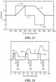
- This unintended stimulation can be mitigated by using short, balanced, biphasic waveform pulses 12, wherein any charge accumulation from the first positive phase 12A of the biphasic waveform 12 is quickly cancelled by a pulse of opposite polarity (that is, the negative phase 12B of the biphasic waveform 12).
- the integrated current 14 has a charge of zero.
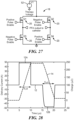
- even a slight asymmetry between the phases 12A, 12B may lead to incomplete cancellation of the charge (for example, as shown in FIG. 24 ).
- FIG. 28 shows the effect of mismatched rise times ⁇ r-positive and ⁇ r-negative between each half of the biphasic pulse (that is, between the positive phase pulse 12A and the negative phase pulse 12B), in which the negative phase takes longer to reach the nominal voltage and leads to a net positive charge.
- US 2016/0058493 A1 relates to a system and method for ablating a tissue site by electroporation with real-time pulse monitoring.
- Some embodiments advantageously provide methods and systems for monitoring and modifying pulsed field ablation (PFA) energy delivery to prevent patient safety risks and/or delivery device failure.
- PFA pulsed field ablation
- some embodiments provide methods and systems for detecting and preventing arcs and arc-induced plasma, and their causal events, during delivery of pulsed field ablation energy, as well as methods and systems for identifying conditions leading to potential delivery device failure and correcting charge imbalance or asymmetry.
- Methods of treatment by therapy or surgery or in vivo diagnosis methods are not encompassed by the wording of the claims but are considered as useful for understanding the invention.
- a method including using at least one detector that measures the rise-fall time of a pulse in its early formation is described herein. If the measured rise-fall time is too short, feedback can be provided to the PFA generator's output stage to temporarily disable the sourcing energy responsible for the oscillation, but then increase the PFA generator's H bridge circuit's rise-fall time, such that the arc, or condition causing an arc, is eliminated for subsequent delivery pulses. As a result, the arc never occurs.
- a second method includes using at least one detector that uses a precise, programmable threshold that suppresses the waveform if a voltage and/or amplitude threshold is reached and/or exceeded (see FIG. 2 ). As the threshold is reached and/or exceeded, a pulse is sent from a detector (or detector-comparator) that is processed within a few nanoseconds and sent as a "kill" signal to the PFA generator's output H bridge circuit.
- a fifth method including applying information gained using one or all of the first three methods, and generating an electronic message advising the operating physician of the recommended course of action to remedy an arc condition that may exist due to a damaged or improperly manipulated catheter.
- a method of modifying pulsed field ablation (PFA) energy delivery comprises: delivering a PFA pulse from a PFA generator; measuring a rise time and a fall time of the PFA pulse; calculating a voltage of an oscillatory pole in the PFA pulsed based at least in part on rise time and the fall time; and modifying at least one of the rise time and the fall time to reduce the voltage of the at least one oscillatory pole in the PFA pulse.
- PFA pulsed field ablation
- the PFA generator further includes processing circuitry having an H bridge circuit.
- modifying the at least one of the rise time and the fall time including adjusting an input resistance in the H bridge circuit.
- modifying at least one of the rise time and the fall time includes reducing the time in which the PFA pulse reaches 90% of a final amplitude of the PFA pulse under heavily loaded conditions.
- the at least one of the rise time and the fall time is modified to a time between 0.3 ⁇ s and 0.5 ⁇ s.
- the method further comprises: measuring a pulse width of the PFA pulse; calculating a voltage of an oscillatory pole in the PFA pulse based at least in part on the pulse width; and modifying the pulse width to reduce the voltage of the at least one oscillatory pole in the PFA pulse.
- the method further comprises ceasing delivery of the PFA pulse from the PFA generator when the calculated voltage of the oscillatory pole is greater than a threshold voltage.
- a method of modifying pulsed field ablation (PFA) energy delivery comprises: delivering at least one biphasic PFA pulse from a PFA generator, each of the at least one biphasic PFA pulse including a biphasic pair having a positive phase and a negative phase; and calculating a value of an integral of a current over the biphasic pair.
- PFA pulsed field ablation
- the method further comprises measuring a pulse width of the PFA pulse; and modifying the pulse width of the biphasic PFA pulse when the integral of the current has a non-zero value.
- the method further comprises delivering a runt pulse in the biphasic PFA pulse and modifying the pulse width of the biphasic PFA pulse when the integral of the current has a non-zero value.
- the runt pulse has an amplitude that is less than an amplitude of the positive phase of the biphasic pair.
- the runt pulse has an amplitude that is less than an amplitude of the negative phase of the biphasic pair.
- a system for delivering pulsed field ablation (PFA) energy comprises: a delivery device including at least one energy delivery electrode; and a control unit in electrical communication with the delivery device, the control unit including a PFA generator.
- the PFA generator has: an H bridge circuit, the H bridge circuit being configured to deliver PFA energy to the delivery device, the PFA energy including a plurality of pulses; a detector, the detector being in electrical communication with the H bridge circuit and configured to: measure a rise-fall time of each of the plurality of pulses; measure a pulse width of each of the plurality of pulses; determine a voltage of at least one pole occurring in at least one of the plurality of pulses; compare the determined voltage of the at least one pole to a threshold voltage; and at least one of: adjust at least one of the rise-fall time and the pulse width of at least one of the plurality of pulses by adjusting a voltage of the PFA energy produced by the H bridge circuit when the detector determines the determined voltage is greater than the threshold voltage; and prompt
- the PFA generator further has a counter circuit in electrical communication with the amplitude detector.
- the amplitude detector is configured to initiate a time count by a timer circuit, the rise-fall time being determined at least in part by the time count.
- control unit being further configured to determine that a fault condition exists in the delivery device, the determination that a fault condition exists being based at least in part on a determined amplitude of at least one of the plurality of pulses.
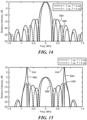
- the bandwidth of the pulse 12 increases, and additional in-band poles 24 are revealed that store, rather than dissipate, energy (for example, as shown in FIG. 12 , where the pulses are designated with reference number 66, and FIG. 15 , where the pulses are designated with reference number 68).
- the stored energy is then released and superimposed on the intended pulse, resulting in high, and possibly damaging, overshoot and ringing (for example, as shown in FIG. 2 ).
- the method disclosed herein includes purposely adjusting the PFA waveform rise and/or fall times ⁇ r and ⁇ f to be as short as possible to minimize imparted energy in the form of heat, while avoiding rise-fall time that create waveform overshoot and ringing.
- excessive ringing such as four times the amplitude
- overshoot may be caused by a rise-fall time that is too fast, and can lead to damage to the delivery device, the waveform or pulse generator (which may also be referred to herein as the PFA generator), and electrical and mechanical components of the delivery device and PFA system, and can potentially cause the formation of coagulants, bubbles, and char, which may present an embolism risk to the patient.
- a pulse 12 from the same PFA generator as in FIG. 2 is shown in FIG. 3 , except where the pulse's rise time ⁇ r is lengthened to approximately 500 ns (from less than 100 ns in FIG. 2 ) to eliminate ringing.
- the PFA system 26 may be used to treat endocardial surfaces, but it will be understood that the PFA system 26 may be used to treat other areas, including epicardial tissue, esophageal tissue, dermal tissue, tumors, or any other tissue that is treated with the application of PFA energy.
- the PFA system 26 generally includes a delivery device 28 and a control unit 30.
- the delivery device 28 may have any suitable size, shape, or configuration, but includes at least one energy delivery electrode 32 for delivering an electrical current, and may further include one or more electrodes such as mapping electrodes and/or electrodes for measuring characteristics such as impedance (not shown).
- the delivery device 28 includes an elongate body 34 with a distal portion 36 and a proximal portion 38, one or more lumens within the elongate body (not shown), and a flexible, expandable distal array 40 coupled to the distal portion 36 of the elongate body 34 and bearing a plurality of energy delivery electrodes 32.
- the plurality of energy delivery electrodes 32 are in electrical communication with the control unit 30.
- the delivery device 28 includes a handle 42 with one or more actuators for, for example, electrically and/or mechanically communicating with one or more steering elements within the delivery device 28 for maneuvering the distal array 40 to a target treatment location within the patient's body.
- the delivery device 28 may also include one or more sensors 44 (for example, associated with each energy delivery electrode, within one or more lumens of the elongate body 34, and/or at other locations in the delivery device 28 and/or control unit 30), such as temperature sensors, pressure sensors, piezoelectric elements, strain gauges, and/or fiber Bragg sensors.
- control unit may be used to generally refer to any system components that are not part of the delivery device 28.
- the control unit 30 may be described to include components that are physically located within or integrated with the control unit 30 or are in communication with the control unit 30.
- the control unit 30 includes a pulse or waveform generator (referred to herein as a PFA generator 22) that is in electrical communication with the energy delivery electrode(s) 32 of the delivery device 28 and configured to deliver pulsed field electrical energy for the treatment of tissue using pulsed field ablation (PFA).
- PFA generator 22 and the control unit 30 are the same component.
- the PFA generator 22 is configured to deliver high-frequency, non-ablative pulses for causing reversible and/or non-reversible electroporation in targeted tissue cells.
- the PFA generator 22 may be configured to deliver ablative energy pulses in the range of approximately 0.1 microsecond to 100 microseconds in duration and at frequencies of approximately 20 Hz to 2000 Hz.
- the PFA generator 22 and/or control unit 30 is configured such that the user is able to modulate or adjust one or more characteristics of the pulses 12, such as rise-fall time ⁇ and/or pulse width T .
- the PFA generator 22 may also be configured to deliver ablative energy (such as radiofrequency (RF) energy, laser energy, microwave energy, or the like) or the control unit 30 may include an additional energy generator for providing ablative energy).
- RF radiofrequency
- control unit 30 also includes a user interface by which the user may select the energy delivery mode, monitor energy delivery parameters, adjust or stop energy delivery, select one or more energy delivery electrodes with which to deliver energy, or the like.
- the user interface may include a foot pedal, mouse, joystick, one or more computers having one or more displays, buttons, knobs, touchpads, touchscreens, or other communication and/or input means 48.
- the PFA generator 22 and/or control unit 30 may be able to operate in a completely automated manner, the PFA generator 22 and/or control unit 30 may be configured to allow the user to assume control over energy delivery and/or to select, initiate, or otherwise assist the semi-automatic operation of the PFA system 26.
- the PFA system 26 may optionally include one or more components such as a navigation system, mapping system, imaging system, delivery device electrode distribution system, remotes, or the like.
- the control unit 30 and/or PFA generator 22 may further include processing circuitry 50 programmed to receive, process, and/or communicate data received from the delivery device 28 and/or other components of the PFA system 26.
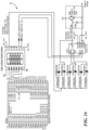
- the PFA generator 22 includes a power source 52 and processing circuitry 50 including an H bridge circuit, such as the H bridge circuit 18 shown in FIG. 5 .
- the H bridge circuit 18 generates positive and negative pulses to create a biphasic waveform 19 that is then transmitted to the energy delivery electrodes 32 of the delivery device 28.
- the energy delivery electrodes 32 then transmit the biphasic waveform (PFA energy) to the targeted tissue.
- the PFA generator 22 and/or the control unit 30 may also include processing circuitry 50 including one or more detectors, counters, or other circuits, such as those discussed below.
- the PFA system 26 also includes at least one detector, which may be integrated with or external to the PFA generator 22.
- the rise-fall time ⁇ is determined by the at least one detector using time domain.
- the PFA system 26 includes an amplitude detector 54, such as the amplitude detector 54 shown in FIG. 6 , that detects the 10% and 90% amplitude of a pulse 12 (such as a trapezoidal pulse) delivered by the PFA generator 22 and initiates a time count by a counter circuit 58 (for example, as shown in FIG. 7 ) that determines the rise and/or fall time of the pulse 12.
- the amplitude detector 54 and counter circuit 58 are together also configured to apply a correction signal based on the determined rise-fall time to change the input base or gate resistance of the H bridge circuit 18. As the input base or gate resistance increases, the gate or base time constant of the RC circuit will increase, and the rise-fall time of the pulse will similarly increase. As will be shown, the effect of slowing rise-fall time will be to greatly attenuate or reduce undesirable overshoot and ringing. Additionally or alternatively, the amplitude detector 54 and counter circuit 58 are configured to apply a correction signal to adjust the pulse width T .
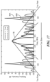
- poles 24 are identified by the at least one spectrum analyzer 60 (for example, the spectrum analyzer 60 shown in FIG. 8 ) using spectral domain.
- the PFA system 26 includes a spectrum detector 60 having an analog-to-digital (A/D) converter 62 that applies a discrete or fast Fourier transform (FFT) 64 on the delivered current to identify oscillatory poles and/or excessively high side lobes 24 in the frequency spectrum of the pulse.
- A/D analog-to-digital
- FFT fast Fourier transform
- FIG. 9 shows a comparison of two trapezoidal pulses in the time domain, the trapezoidal pulses having different rise-fall times ⁇ (0.1 ⁇ s and 0.5 ⁇ s), but the same pulse width T (3 ⁇ s).
- the Bode plot magnitude response for Equation (2) in the trapezoidal pulse frequency spectrum is show in FIG. 11 , where both amplitude and frequency are plotted on logarithmic axes.
- the rise-fall time ⁇ (also referred to as ⁇ r / ⁇ f ) is adjusted.
- Two time domain trapezoidal pulses 12 with different rise-fall times, ⁇ are shown in FIG. 9 .
- ⁇ 0.1 ⁇ s.
- ⁇ 0.5 ⁇ s.
- the frequency spectrums of the two pulses 66A, 66B are compared in FIG. 10 . It is noted that the second trapezoidal pulse 66B has a wider spectral width than the first trapezoidal pulse 66A.
- a second method of reducing ringing includes of adjusting the pulse width parameter, T , to cause pole(s) 24 to occur at area(s) on the trapezoid pulse waveform 12 that are at minima between sidelobes, or null(s).
- T the pulse width parameter
- FIG. 13 is a graphical comparison of two trapezoidal pulses 68A, 68B in the time domain, with both pulses having the same rise-fall time ⁇ but different pulse widths T .
- the controller includes sensors or detectors that monitor the amount of charge delivered and/or an integral of that charge and provide feedback to the H bridge circuit 18.
- the H bridge circuit 18 uses data received by the sensors to dynamically tune the amount of charge compensation provided, either automatically or semi-automatically (for example, at user initiation).
- An exemplary circuit 92 used to provide such feedback is shown in FIG. 33 .
- the circuit 92 of FIG. 33 dynamically monitors charge delivered to the patient and sends a digital pulse when the accumulated charge returns to zero after having first risen past a threshold value.
- the control unit 30 and/or PFA generator 22 can use this digital pulse as feedback to indicate when the runt pulse or pulse width adjustment has fully balanced the charge.
- the circuit 92 sends a digital pulse within a predetermined time period before the charge returns to zero to account for delays while the controller reacts to the digital signal.
Landscapes
- Health & Medical Sciences (AREA)
- Life Sciences & Earth Sciences (AREA)
- Engineering & Computer Science (AREA)
- Surgery (AREA)
- Animal Behavior & Ethology (AREA)
- Veterinary Medicine (AREA)
- Nuclear Medicine, Radiotherapy & Molecular Imaging (AREA)
- Public Health (AREA)
- Biomedical Technology (AREA)
- General Health & Medical Sciences (AREA)
- Otolaryngology (AREA)
- Molecular Biology (AREA)
- Medical Informatics (AREA)
- Heart & Thoracic Surgery (AREA)
- Physics & Mathematics (AREA)
- Plasma & Fusion (AREA)
- Cardiology (AREA)
- Biophysics (AREA)
- Radiology & Medical Imaging (AREA)
- Surgical Instruments (AREA)
- Electrotherapy Devices (AREA)
Claims (15)
- Steuereinheit (30) zur Modifizierung der Energieabgabe über gepulste Feldablation (PFA), wobei die Steuereinheit dazu ausgelegt ist:einen PFA-Impuls aus einem PFA-Generator (22) abzugeben;eine Anstiegszeit und eine Abfallzeit (τ) des PFA-Impulses zu messen;eine Spannung eines oszillierenden Poles (24) in dem PFA-Impuls basierend zumindest teilweise auf der Anstiegszeit und der Abfallzeit zu berechnen; undmindestens eine der Anstiegszeit und der Abfallzeit zu modifizieren, um die Spannung des mindestens einen oszillierenden Poles in dem PFA-Impuls zu reduzieren.
- Steuereinheit nach Anspruch 1, wobei der PFA-Generator ferner eine Verarbeitungsschaltung (50) mit einer H-Brückenschaltung (18) aufweist, die die mindestens eine der Anstiegszeit und der Abfallzeit modifiziert und einen Eingangswiderstand in der H-Brückenschaltung einstellt.
- Steuereinheit nach einem der Ansprüche 1-2, wobei das Modifizieren von mindestens einer der Anstiegszeit und der Abfallzeit das Reduzieren der Zeit aufweist, in der der PFA-Impuls 90% einer finalen Amplitude des PFA-Impulses unter starker Belastung aufweist.
- Steuereinheit nach einem der Ansprüche 1-3, wobei die mindestens eine der Anstiegszeit und der Abfallzeit auf eine Zeit zwischen 0,3 µs und 0,5 µs modifiziert wird.
- Steuereinheit nach einem der Ansprüche 1-4, wobei die Steuereinheit ferner dazu ausgelegt ist:eine Impulsbreite (T) des PFA-Impulses zu messen;eine Spannung eines oszillierenden Poles in dem PFA-Impuls basierend zumindest teilweise auf der Anstiegszeit und der Abfallzeit zu berechnen; unddie Impulsbreite zu modifizieren, um die Spannung des mindestens einen oszillierenden Poles in dem PFA-Impuls zu reduzieren.
- Steuereinheit nach einem der Ansprüche 1-5, die ferner dazu ausgelegt ist, die Abgabe des PFA-Impulses aus dem PFA-Generator zu beenden, wenn die berechnete Spannung des oszillierenden Poles größer ist als eine Schwellspannung.
- Steuereinheit nach einem der Ansprüche 1-5, wobei die Abgabe des PFA-Impulses aus dem PFA-Generator die Abgabe von mindestens einem zweiphasigen PFA-Impuls aus dem PFA-Generator ist, wobei jeder des mindestens einen zweiphasigen PFA-Impulses ein zweiphasiges Paar mit einer positiven Phase und einer negativen Phase aufweist und die Steuereinheit ferner dazu ausgelegt ist, einen Wert eines Stromintegrals über dem zweiphasigen Paar zu berechnen.
- Steuereinheit nach Anspruch 7, die ferner dazu ausgelegt ist:eine Impulsbreite des PFA-Impulses zu messen; unddie Impulsbreite des zweiphasigen PFA-Impulses zu modifizieren, wenn das Stromintegral einen von Null verschiedenen Wert hat.
- Steuereinheit nach einem der Ansprüche 7-8, die ferner dazu ausgelegt ist, einen Runt-Impuls in dem zweiphasigen PFA-Impuls abzugeben und die Impulsbreite des zweiphasigen PFA-Impulses zu modifizieren, wenn das Stromintegral einen von Null verschiedenen Wert hat.
- Steuereinheit nach Anspruch 9, wobei der Runt-Impuls eine Amplitude hat, die kleiner ist als eine Amplitude der positiven Phase des zweiphasigen Paares.
- Steuereinheit nach einem der Ansprüche 9-10, wobei der Runt-Impuls nach der negativen Phase des zweiphasigen Paares abgegeben wird.
- Steuereinheit nach einem der Ansprüche 1-11, ferner umfassend eine Abgabevorrichtung, die mindestens eine Energieabgabeelektrode aufweist, wobei die Steuereinheit mit der Abgabevorrichtung (28) in elektrischer Verbindung ist.
- Steuereinheit nach einem der Ansprüche 2-12, ferner aufweisend:
einen Detektor, wobei der Detektor mit der H-Brückenschaltung in elektrischer Verbindung und dazu ausgelegt ist:eine Anstiegszeit eines jeden der Vielzahl von Impulsen zu messen;eine Impulsbreite eines jeden der Vielzahl von Impulsen zu messen;eine Spannung von mindestens einem Pol zu bestimmen, der in mindestens einem der Vielzahl von Impulsen auftritt;die bestimmte Spannung des mindestens einen Poles mit einer Schwellspannung zu vergleichen; undmindestens eins der Folgenden:mindestens eine der Anstiegs-Abfallzeit und der Impulsbreite von mindestens einem der Vielzahl von Impulsen durch Einstellen einer Spannung der von der H-Brückenschaltung produzierten PFA-Energie einzustellen, wenn der Detektor bestimmt, dass die bestimmte Spannung größer ist als die Schwellspannung; undeinen Benutzer anzuweisen, einen Ausgangspegel des PFA-Generators zu senken. - Steuereinheit nach Anspruch 13, wobei der Detektor ein Amplitudendetektor (54) ist, wobei der Amplitudendetektor dazu ausgelegt ist, eine Amplitude eines jeden der Vielzahl von Impulsen in einem Zeitbereich zu bestimmen.
- Steuereinheit nach einem der Ansprüche 13-14, wobei der PFA-Generator eine Zählerschaltung in elektrischer Verbindung mit dem Amplitudendetektor hat.
Applications Claiming Priority (2)
| Application Number | Priority Date | Filing Date | Title |
|---|---|---|---|
| US201862756810P | 2018-11-07 | 2018-11-07 | |
| PCT/US2019/060179 WO2020097276A2 (en) | 2018-11-07 | 2019-11-07 | Methods of recognizing and eliminating arcs and arc induced plasma during energy delivery in tissue |
Publications (2)
| Publication Number | Publication Date |
|---|---|
| EP3876855A2 EP3876855A2 (de) | 2021-09-15 |
| EP3876855B1 true EP3876855B1 (de) | 2025-06-25 |
Family
ID=69160052
Family Applications (1)
| Application Number | Title | Priority Date | Filing Date |
|---|---|---|---|
| EP19836013.3A Active EP3876855B1 (de) | 2018-11-07 | 2019-11-07 | Vorrichtung zur erkennung und beseitigung von lichtbögen und lichtbogeninduziertem plasma während der energieabgabe in gewebe |
Country Status (4)
| Country | Link |
|---|---|
| US (1) | US11612424B2 (de) |
| EP (1) | EP3876855B1 (de) |
| CN (1) | CN112969425B (de) |
| WO (1) | WO2020097276A2 (de) |
Families Citing this family (24)
| Publication number | Priority date | Publication date | Assignee | Title |
|---|---|---|---|---|
| US11337749B2 (en) | 2015-10-07 | 2022-05-24 | Mayo Foundation For Medical Education And Research | Electroporation for obesity or diabetes treatment |
| US11717337B2 (en) | 2016-11-29 | 2023-08-08 | St. Jude Medical, Cardiology Division, Inc. | Electroporation systems and catheters for electroporation systems |
| WO2018191113A1 (en) | 2017-04-10 | 2018-10-18 | St. Jude Medical, Cardiology Division, Inc. | Electroporation system and method of preconditioning tissue for electroporation therapy |
| EP3937812B1 (de) * | 2019-03-15 | 2025-04-23 | Boston Scientific Scimed, Inc. | Wellengenerator und steuerung für die selektive zellablation |
| WO2020190688A1 (en) * | 2019-03-15 | 2020-09-24 | Boston Scientific Scimed, Inc. | Spatially multiplexed waveform for selective cell ablation |
| EP3937811B1 (de) * | 2019-03-15 | 2024-07-10 | Boston Scientific Scimed, Inc. | Zeitmultiplexierte wellenform zur selektiven zellablation |
| EP4048179A1 (de) * | 2019-10-21 | 2022-08-31 | Endogenex, Inc. | Vorrichtungen, systeme und verfahren zur behandlung des zwölffingerdarms mit einem gepulsten elektrischen feld |
| US11497541B2 (en) | 2019-11-20 | 2022-11-15 | Boston Scientific Scimed, Inc. | Systems, apparatuses, and methods for protecting electronic components from high power noise induced by high voltage pulses |
| US11065047B2 (en) | 2019-11-20 | 2021-07-20 | Farapulse, Inc. | Systems, apparatuses, and methods for protecting electronic components from high power noise induced by high voltage pulses |
| US20210275249A1 (en) * | 2020-03-09 | 2021-09-09 | Boston Scientific Scimed, Inc. | Laser pulse shaping to enhance conversion efficiency and protect fiber optic delivery system for disruption of vascular calcium |
| US20230200893A1 (en) * | 2020-06-03 | 2023-06-29 | St. Jude Medical, Cardiology Division, Inc. | System for irreversible electroporation |
| US20220022953A1 (en) * | 2020-07-24 | 2022-01-27 | Boston Scientific Scimed, Inc. | Esophagus catheter for irreversible electroporation |
| US12076071B2 (en) * | 2020-08-14 | 2024-09-03 | Kardium Inc. | Systems and methods for treating tissue with pulsed field ablation |
| US20220192741A1 (en) * | 2020-12-23 | 2022-06-23 | Kardium Inc. | Systems and methods for treating tissue with pulsed field ablation |
| US12082877B2 (en) | 2021-01-22 | 2024-09-10 | CRC EP, Inc. | Ablation catheter and operation method of same |
| US20220241008A1 (en) * | 2021-02-03 | 2022-08-04 | Biosense Webster (Israel) Ltd. | Virtually-shorted electrodes for an ire pulse generator |
| US20230052114A1 (en) * | 2021-08-12 | 2023-02-16 | St. Jude Medical, Cardiology Division, Inc. | Systems and methods for electroporation using asymmetric waveforms and waveforms with reduced burst duration |
| WO2023147319A1 (en) * | 2022-01-28 | 2023-08-03 | St. Jude Medical, Cardiology Division, Inc. | Systems and methods for electroporation using waveforms that reduce electrical stimulation |
| WO2023150215A1 (en) * | 2022-02-03 | 2023-08-10 | CRC EP, Inc. | Systems and methods for pulsed-field ablation with charge-balanced waveforms |
| CN115005961B (zh) * | 2022-07-07 | 2023-05-12 | 上海普实医疗器械股份有限公司 | 心脏脉冲电场消融系统 |
| CN115429424B (zh) * | 2022-09-06 | 2023-03-28 | 中国人民解放军空军军医大学 | 一种低温等离子体手术电路 |
| WO2024075034A1 (en) | 2022-10-05 | 2024-04-11 | Btl Medical Technologies S.R.O. | Pulsed field ablation device and method |
| CN120358995A (zh) * | 2022-12-14 | 2025-07-22 | 美敦力公司 | 用于脉冲场消融系统的异常脉冲递送保护 |
| DE102023133549A1 (de) | 2023-11-30 | 2025-06-05 | Stockert Gmbh | Vorrichtung, Verfahren und System zur irreversiblen Elektroporation von Gewebe |
Citations (1)
| Publication number | Priority date | Publication date | Assignee | Title |
|---|---|---|---|---|
| US20110087212A1 (en) * | 2009-10-09 | 2011-04-14 | Ethicon Endo-Surgery, Inc. | Surgical generator for ultrasonic and electrosurgical devices |
Family Cites Families (27)
| Publication number | Priority date | Publication date | Assignee | Title |
|---|---|---|---|---|
| US5601608A (en) | 1995-02-02 | 1997-02-11 | Pacesetter, Inc. | Methods and apparatus for applying charge-balanced antiarrhythmia shocks |
| US5713935A (en) | 1996-08-23 | 1998-02-03 | Sulzer Intermedics Inc. | Method and apparatus for monitored biphasic cardiac impedance sensing |
| US6449294B1 (en) * | 1999-07-26 | 2002-09-10 | Pls Liquidating Llc | Single dominant spike output erbium laser |
| GB0624658D0 (en) * | 2006-12-11 | 2007-01-17 | Medical Device Innovations Ltd | Electrosurgical ablation apparatus and a method of ablating biological tissue |
| WO2009076246A2 (en) * | 2007-12-06 | 2009-06-18 | Massachusetts Institute Of Technology | Methods to treat unwanted tissue with electric pulses |
| US20170049513A1 (en) * | 2009-11-06 | 2017-02-23 | Cosman Medical, Inc. | Multiple electrode generator |
| US20130041355A1 (en) * | 2011-08-11 | 2013-02-14 | Tammo Heeren | Reducing Damage From A Dielectric Breakdown in Surgical Applications |
| US9351790B2 (en) * | 2011-09-17 | 2016-05-31 | M.O.E. Medical Devices Llc | Electrode geometries and method for applying electric field treatment to parts of the body |
| US20130110093A1 (en) * | 2011-10-19 | 2013-05-02 | Iridex Corporation | Slit lamp grid pattern laser treatment adapter |
| US8868178B2 (en) * | 2012-12-11 | 2014-10-21 | Galvani, Ltd. | Arrhythmia electrotherapy device and method with provisions for mitigating patient discomfort |
| CA2906229C (en) * | 2013-03-15 | 2020-08-11 | Myndtec Inc. | Electrical stimulation system with pulse control |
| US10201383B2 (en) * | 2013-03-15 | 2019-02-12 | Retrovascular, Inc. | Methods for tissue ablation measurement and control and devices thereof |
| US10154869B2 (en) * | 2013-08-02 | 2018-12-18 | Gary M. Onik | System and method for creating radio-frequency energy electrical membrane breakdown for tissue ablation |
| US9956422B2 (en) * | 2014-04-24 | 2018-05-01 | Medtronic, Inc. | Therapy delivery methods and circuits for an implantable medical device |
| WO2015171921A2 (en) * | 2014-05-07 | 2015-11-12 | Mickelson Steven R | Methods and apparatus for selective tissue ablation |
| ES2945708T3 (es) * | 2014-05-16 | 2023-07-06 | Applied Med Resources | Sistema electroquirúrgico |
| US12114911B2 (en) | 2014-08-28 | 2024-10-15 | Angiodynamics, Inc. | System and method for ablating a tissue site by electroporation with real-time pulse monitoring |
| US20180071014A1 (en) * | 2015-04-10 | 2018-03-15 | Angiodynamics, Inc. | System and Methods for Irreversible Electroporation with Thermally Controlled Electrodes |
| EP3288471A1 (de) | 2015-05-01 | 2018-03-07 | Inter Science GmbH | Verfahren, systeme und vorrichtungen zur gewebeablation mithilfe von impulsformdesigns |
| DE202016009219U1 (de) * | 2015-08-06 | 2024-05-13 | Medtronic, Inc. | Herzablation mittels gepulsten Feldes |
| US10548665B2 (en) * | 2016-02-29 | 2020-02-04 | Pulse Biosciences, Inc. | High-voltage analog circuit pulser with feedback control |
| US20170319851A1 (en) * | 2016-05-06 | 2017-11-09 | Pulse Biosciences, Inc. | Low-voltage impedance check pulse generator |
| CN110198680B (zh) * | 2016-11-16 | 2022-09-13 | 纳维斯国际有限公司 | 消融有效性估计器 |
| US11229478B2 (en) * | 2017-02-08 | 2022-01-25 | Medtronic, Inc. | Profile parameter selection algorithm for electroporation |
| EP3614946B1 (de) * | 2017-04-27 | 2024-03-20 | EPiX Therapeutics, Inc. | Bestimmung der art des kontaktes zwischen katheterspitze und gewebe |
| CN107681916A (zh) * | 2017-09-22 | 2018-02-09 | 重庆大学 | 一种协同脉冲不可逆电穿孔装置 |
| CN112804955B (zh) * | 2018-10-05 | 2024-10-11 | Epix疗法公司 | 用于损伤形成评估和显示的系统 |
-
2019
- 2019-11-07 WO PCT/US2019/060179 patent/WO2020097276A2/en not_active Ceased
- 2019-11-07 CN CN201980073040.XA patent/CN112969425B/zh active Active
- 2019-11-07 US US16/676,586 patent/US11612424B2/en active Active
- 2019-11-07 EP EP19836013.3A patent/EP3876855B1/de active Active
Patent Citations (1)
| Publication number | Priority date | Publication date | Assignee | Title |
|---|---|---|---|---|
| US20110087212A1 (en) * | 2009-10-09 | 2011-04-14 | Ethicon Endo-Surgery, Inc. | Surgical generator for ultrasonic and electrosurgical devices |
Also Published As
| Publication number | Publication date |
|---|---|
| WO2020097276A2 (en) | 2020-05-14 |
| CN112969425A (zh) | 2021-06-15 |
| US20200138506A1 (en) | 2020-05-07 |
| EP3876855A2 (de) | 2021-09-15 |
| US11612424B2 (en) | 2023-03-28 |
| WO2020097276A3 (en) | 2020-06-18 |
| CN112969425B (zh) | 2024-08-30 |
Similar Documents
| Publication | Publication Date | Title |
|---|---|---|
| EP3876855B1 (de) | Vorrichtung zur erkennung und beseitigung von lichtbögen und lichtbogeninduziertem plasma während der energieabgabe in gewebe | |
| US11399885B2 (en) | Power monitoring circuitry and method for reducing leakage current in RF generators | |
| US20240252225A1 (en) | Methods of ensuring pulsed field ablation generator system electrical safety | |
| EP1719471B1 (de) | Kontakterkennungssystem für Vielfachneutralelektroden | |
| US9839470B2 (en) | Electrosurgical generator for minimizing neuromuscular stimulation | |
| EP1280467B1 (de) | Mehrkanaliges hochfrequenzabgabesystem mit koagulierungsreduktion | |
| US20240398464A1 (en) | Closed-loop control system for pulse ablation | |
| US20230397945A1 (en) | Power apparatus, control and inverters for electrosurgery | |
| CN103237516A (zh) | 用于适应性rf消融的系统和方法 | |
| US20140148802A1 (en) | Radio Frequency Procedure Protection | |
| US20240374300A1 (en) | Systems and methods for treating tissue with pulsed field ablation | |
| KR20220033002A (ko) | 임피던스 기반 비가역적 전기천공(ire) | |
| EP4240266B1 (de) | System und verfahren zur erkennung der anwendung eines erdungspads für ablationsvorrichtungen | |
| US12611243B2 (en) | Power monitoring circuitry and method for reducing leakage current in RF generators | |
| US20250177030A1 (en) | Device, Method and System for the Irreversible Electroporation of Tissue |
Legal Events
| Date | Code | Title | Description |
|---|---|---|---|
| STAA | Information on the status of an ep patent application or granted ep patent |
Free format text: STATUS: UNKNOWN |
|
| STAA | Information on the status of an ep patent application or granted ep patent |
Free format text: STATUS: THE INTERNATIONAL PUBLICATION HAS BEEN MADE |
|
| PUAI | Public reference made under article 153(3) epc to a published international application that has entered the european phase |
Free format text: ORIGINAL CODE: 0009012 |
|
| STAA | Information on the status of an ep patent application or granted ep patent |
Free format text: STATUS: REQUEST FOR EXAMINATION WAS MADE |
|
| 17P | Request for examination filed |
Effective date: 20210531 |
|
| AK | Designated contracting states |
Kind code of ref document: A2 Designated state(s): AL AT BE BG CH CY CZ DE DK EE ES FI FR GB GR HR HU IE IS IT LI LT LU LV MC MK MT NL NO PL PT RO RS SE SI SK SM TR |
|
| DAV | Request for validation of the european patent (deleted) | ||
| DAX | Request for extension of the european patent (deleted) | ||
| STAA | Information on the status of an ep patent application or granted ep patent |
Free format text: STATUS: EXAMINATION IS IN PROGRESS |
|
| 17Q | First examination report despatched |
Effective date: 20240227 |
|
| GRAP | Despatch of communication of intention to grant a patent |
Free format text: ORIGINAL CODE: EPIDOSNIGR1 |
|
| STAA | Information on the status of an ep patent application or granted ep patent |
Free format text: STATUS: GRANT OF PATENT IS INTENDED |
|
| RIC1 | Information provided on ipc code assigned before grant |
Ipc: A61N 1/05 20060101ALI20241127BHEP Ipc: A61N 1/32 20060101ALI20241127BHEP Ipc: A61B 18/12 20060101AFI20241127BHEP |
|
| INTG | Intention to grant announced |
Effective date: 20241205 |
|
| GRAJ | Information related to disapproval of communication of intention to grant by the applicant or resumption of examination proceedings by the epo deleted |
Free format text: ORIGINAL CODE: EPIDOSDIGR1 |
|
| STAA | Information on the status of an ep patent application or granted ep patent |
Free format text: STATUS: EXAMINATION IS IN PROGRESS |
|
| GRAP | Despatch of communication of intention to grant a patent |
Free format text: ORIGINAL CODE: EPIDOSNIGR1 |
|
| STAA | Information on the status of an ep patent application or granted ep patent |
Free format text: STATUS: GRANT OF PATENT IS INTENDED |
|
| INTG | Intention to grant announced |
Effective date: 20250304 |
|
| GRAS | Grant fee paid |
Free format text: ORIGINAL CODE: EPIDOSNIGR3 |
|
| GRAA | (expected) grant |
Free format text: ORIGINAL CODE: 0009210 |
|
| STAA | Information on the status of an ep patent application or granted ep patent |
Free format text: STATUS: THE PATENT HAS BEEN GRANTED |
|
| AK | Designated contracting states |
Kind code of ref document: B1 Designated state(s): AL AT BE BG CH CY CZ DE DK EE ES FI FR GB GR HR HU IE IS IT LI LT LU LV MC MK MT NL NO PL PT RO RS SE SI SK SM TR |
|
| REG | Reference to a national code |
Ref country code: GB Ref legal event code: FG4D |
|
| REG | Reference to a national code |
Ref country code: CH Ref legal event code: EP |
|
| REG | Reference to a national code |
Ref country code: CH Ref legal event code: EP |
|
| REG | Reference to a national code |
Ref country code: IE Ref legal event code: FG4D |
|
| REG | Reference to a national code |
Ref country code: DE Ref legal event code: R096 Ref document number: 602019071679 Country of ref document: DE |
|
| PG25 | Lapsed in a contracting state [announced via postgrant information from national office to epo] |
Ref country code: FI Free format text: LAPSE BECAUSE OF FAILURE TO SUBMIT A TRANSLATION OF THE DESCRIPTION OR TO PAY THE FEE WITHIN THE PRESCRIBED TIME-LIMIT Effective date: 20250625 |
|
| REG | Reference to a national code |
Ref country code: LT Ref legal event code: MG9D |
|
| PG25 | Lapsed in a contracting state [announced via postgrant information from national office to epo] |
Ref country code: NO Free format text: LAPSE BECAUSE OF FAILURE TO SUBMIT A TRANSLATION OF THE DESCRIPTION OR TO PAY THE FEE WITHIN THE PRESCRIBED TIME-LIMIT Effective date: 20250925 Ref country code: GR Free format text: LAPSE BECAUSE OF FAILURE TO SUBMIT A TRANSLATION OF THE DESCRIPTION OR TO PAY THE FEE WITHIN THE PRESCRIBED TIME-LIMIT Effective date: 20250926 |
|
| PG25 | Lapsed in a contracting state [announced via postgrant information from national office to epo] |
Ref country code: BG Free format text: LAPSE BECAUSE OF FAILURE TO SUBMIT A TRANSLATION OF THE DESCRIPTION OR TO PAY THE FEE WITHIN THE PRESCRIBED TIME-LIMIT Effective date: 20250625 |
|
| PG25 | Lapsed in a contracting state [announced via postgrant information from national office to epo] |
Ref country code: HR Free format text: LAPSE BECAUSE OF FAILURE TO SUBMIT A TRANSLATION OF THE DESCRIPTION OR TO PAY THE FEE WITHIN THE PRESCRIBED TIME-LIMIT Effective date: 20250625 |
|
| PG25 | Lapsed in a contracting state [announced via postgrant information from national office to epo] |
Ref country code: RS Free format text: LAPSE BECAUSE OF FAILURE TO SUBMIT A TRANSLATION OF THE DESCRIPTION OR TO PAY THE FEE WITHIN THE PRESCRIBED TIME-LIMIT Effective date: 20250925 |
|
| PG25 | Lapsed in a contracting state [announced via postgrant information from national office to epo] |
Ref country code: LV Free format text: LAPSE BECAUSE OF FAILURE TO SUBMIT A TRANSLATION OF THE DESCRIPTION OR TO PAY THE FEE WITHIN THE PRESCRIBED TIME-LIMIT Effective date: 20250625 |
|
| REG | Reference to a national code |
Ref country code: NL Ref legal event code: MP Effective date: 20250625 |
|
| PG25 | Lapsed in a contracting state [announced via postgrant information from national office to epo] |
Ref country code: NL Free format text: LAPSE BECAUSE OF FAILURE TO SUBMIT A TRANSLATION OF THE DESCRIPTION OR TO PAY THE FEE WITHIN THE PRESCRIBED TIME-LIMIT Effective date: 20250625 |
|
| PG25 | Lapsed in a contracting state [announced via postgrant information from national office to epo] |
Ref country code: PT Free format text: LAPSE BECAUSE OF FAILURE TO SUBMIT A TRANSLATION OF THE DESCRIPTION OR TO PAY THE FEE WITHIN THE PRESCRIBED TIME-LIMIT Effective date: 20251027 |
|
| REG | Reference to a national code |
Ref country code: AT Ref legal event code: MK05 Ref document number: 1805657 Country of ref document: AT Kind code of ref document: T Effective date: 20250625 |
|
| PG25 | Lapsed in a contracting state [announced via postgrant information from national office to epo] |
Ref country code: IS Free format text: LAPSE BECAUSE OF FAILURE TO SUBMIT A TRANSLATION OF THE DESCRIPTION OR TO PAY THE FEE WITHIN THE PRESCRIBED TIME-LIMIT Effective date: 20251025 |
|
| PGFP | Annual fee paid to national office [announced via postgrant information from national office to epo] |
Ref country code: DE Payment date: 20251022 Year of fee payment: 7 |
|
| PG25 | Lapsed in a contracting state [announced via postgrant information from national office to epo] |
Ref country code: AT Free format text: LAPSE BECAUSE OF FAILURE TO SUBMIT A TRANSLATION OF THE DESCRIPTION OR TO PAY THE FEE WITHIN THE PRESCRIBED TIME-LIMIT Effective date: 20250625 Ref country code: SM Free format text: LAPSE BECAUSE OF FAILURE TO SUBMIT A TRANSLATION OF THE DESCRIPTION OR TO PAY THE FEE WITHIN THE PRESCRIBED TIME-LIMIT Effective date: 20250625 |
|
| PGFP | Annual fee paid to national office [announced via postgrant information from national office to epo] |
Ref country code: FR Payment date: 20251022 Year of fee payment: 7 |
|
| PG25 | Lapsed in a contracting state [announced via postgrant information from national office to epo] |
Ref country code: CZ Free format text: LAPSE BECAUSE OF FAILURE TO SUBMIT A TRANSLATION OF THE DESCRIPTION OR TO PAY THE FEE WITHIN THE PRESCRIBED TIME-LIMIT Effective date: 20250625 |
|
| PG25 | Lapsed in a contracting state [announced via postgrant information from national office to epo] |
Ref country code: PL Free format text: LAPSE BECAUSE OF FAILURE TO SUBMIT A TRANSLATION OF THE DESCRIPTION OR TO PAY THE FEE WITHIN THE PRESCRIBED TIME-LIMIT Effective date: 20250625 |
|
| PG25 | Lapsed in a contracting state [announced via postgrant information from national office to epo] |
Ref country code: EE Free format text: LAPSE BECAUSE OF FAILURE TO SUBMIT A TRANSLATION OF THE DESCRIPTION OR TO PAY THE FEE WITHIN THE PRESCRIBED TIME-LIMIT Effective date: 20250625 |
|
| PG25 | Lapsed in a contracting state [announced via postgrant information from national office to epo] |
Ref country code: SK Free format text: LAPSE BECAUSE OF FAILURE TO SUBMIT A TRANSLATION OF THE DESCRIPTION OR TO PAY THE FEE WITHIN THE PRESCRIBED TIME-LIMIT Effective date: 20250625 |
|
| PG25 | Lapsed in a contracting state [announced via postgrant information from national office to epo] |
Ref country code: ES Free format text: LAPSE BECAUSE OF FAILURE TO SUBMIT A TRANSLATION OF THE DESCRIPTION OR TO PAY THE FEE WITHIN THE PRESCRIBED TIME-LIMIT Effective date: 20250625 |
|
| PG25 | Lapsed in a contracting state [announced via postgrant information from national office to epo] |
Ref country code: RO Free format text: LAPSE BECAUSE OF FAILURE TO SUBMIT A TRANSLATION OF THE DESCRIPTION OR TO PAY THE FEE WITHIN THE PRESCRIBED TIME-LIMIT Effective date: 20250625 |
|
| PG25 | Lapsed in a contracting state [announced via postgrant information from national office to epo] |
Ref country code: DK Free format text: LAPSE BECAUSE OF FAILURE TO SUBMIT A TRANSLATION OF THE DESCRIPTION OR TO PAY THE FEE WITHIN THE PRESCRIBED TIME-LIMIT Effective date: 20250625 |
|
| PG25 | Lapsed in a contracting state [announced via postgrant information from national office to epo] |
Ref country code: IT Free format text: LAPSE BECAUSE OF FAILURE TO SUBMIT A TRANSLATION OF THE DESCRIPTION OR TO PAY THE FEE WITHIN THE PRESCRIBED TIME-LIMIT Effective date: 20250625 |