EP3877280B1 - Bouchon à vis en plastique attaché - Google Patents
Bouchon à vis en plastique attaché Download PDFInfo
- Publication number
- EP3877280B1 EP3877280B1 EP19880856.0A EP19880856A EP3877280B1 EP 3877280 B1 EP3877280 B1 EP 3877280B1 EP 19880856 A EP19880856 A EP 19880856A EP 3877280 B1 EP3877280 B1 EP 3877280B1
- Authority
- EP
- European Patent Office
- Prior art keywords
- stopper
- bridges
- link
- tamper
- tamper band
- Prior art date
- Legal status (The legal status is an assumption and is not a legal conclusion. Google has not performed a legal analysis and makes no representation as to the accuracy of the status listed.)
- Active
Links
Images



Classifications
-
- B—PERFORMING OPERATIONS; TRANSPORTING
- B65—CONVEYING; PACKING; STORING; HANDLING THIN OR FILAMENTARY MATERIAL
- B65D—CONTAINERS FOR STORAGE OR TRANSPORT OF ARTICLES OR MATERIALS, e.g. BAGS, BARRELS, BOTTLES, BOXES, CANS, CARTONS, CRATES, DRUMS, JARS, TANKS, HOPPERS, FORWARDING CONTAINERS; ACCESSORIES, CLOSURES, OR FITTINGS THEREFOR; PACKAGING ELEMENTS; PACKAGES
- B65D55/00—Accessories for container closures not otherwise provided for
- B65D55/16—Devices preventing loss of removable closure members
-
- B—PERFORMING OPERATIONS; TRANSPORTING
- B65—CONVEYING; PACKING; STORING; HANDLING THIN OR FILAMENTARY MATERIAL
- B65D—CONTAINERS FOR STORAGE OR TRANSPORT OF ARTICLES OR MATERIALS, e.g. BAGS, BARRELS, BOTTLES, BOXES, CANS, CARTONS, CRATES, DRUMS, JARS, TANKS, HOPPERS, FORWARDING CONTAINERS; ACCESSORIES, CLOSURES, OR FITTINGS THEREFOR; PACKAGING ELEMENTS; PACKAGES
- B65D41/00—Caps, e.g. crown caps or crown seals, i.e. members having parts arranged for engagement with the external periphery of a neck or wall defining a pouring opening or discharge aperture; Protective cap-like covers for closure members, e.g. decorative covers of metal foil or paper
- B65D41/32—Caps or cap-like covers with lines of weakness, tearing-strips, tags, or like opening or removal devices, e.g. to facilitate formation of pouring openings
- B65D41/34—Threaded or like caps or cap-like covers provided with tamper elements formed in, or attached to, the closure skirt
-
- B—PERFORMING OPERATIONS; TRANSPORTING
- B65—CONVEYING; PACKING; STORING; HANDLING THIN OR FILAMENTARY MATERIAL
- B65D—CONTAINERS FOR STORAGE OR TRANSPORT OF ARTICLES OR MATERIALS, e.g. BAGS, BARRELS, BOTTLES, BOXES, CANS, CARTONS, CRATES, DRUMS, JARS, TANKS, HOPPERS, FORWARDING CONTAINERS; ACCESSORIES, CLOSURES, OR FITTINGS THEREFOR; PACKAGING ELEMENTS; PACKAGES
- B65D2401/00—Tamper-indicating means
- B65D2401/15—Tearable part of the closure
- B65D2401/30—Tamper-ring remaining connected to closure after initial removal
Definitions
- This invention relates to a tethered plastic screw stopper.
- a container In the field of liquid packaging, it is very common to seal the aperture of a container with a stopper, often made from a plastic material.
- a stopper often made from a plastic material.
- Such container is usually a plastic or glass bottle, but other materials may be used as well.
- the stopper has a tubular shape closed at its top edge by a top wall.
- the stopper comprises a roof attached to a tamper shell through bridges. Bridges are distributed around the circumference of the roof and the tamper shall. The bridges may be made when molding the stopper or after through undergoing a cutting step during the manufacturing process.
- the bottle neck includes outer fixation feature, such as thread(s) for screw type stopper or annular fixation rings for snap type stopper, to secure the stopper on the bottle neck.
- outer fixation feature such as thread(s) for screw type stopper or annular fixation rings for snap type stopper, to secure the stopper on the bottle neck.
- the tamper shell comprises inner thread(s) arranged inside side walls.
- the bottle neck fixation feature may include outer thread(s). Such combination of outer and inner thread(s) allows the stopper to be screwed on a bottle neck to seal it and unscrewed for bottle opening.
- a snap type stopper may include an inner annular area and the bottle neck fixation feature may include outer fixation ring, in order to slot in force the stopper on the bottle neck.
- a snap type stopper may include a tamper shell with a movable sealing roof from a closed position to a partial opening position, and reversely. The roof may be separated upon opening or may be connected to the tamper shell.
- the tamper shell may be secured around the bottle neck through inner shell retaining features or through the retaining features diameter being smaller than a diameter of a tamper shell of the bottle neck.
- the roof may be removable.
- the bridges form a weakness line and may be torn apart from the roof, separating it from the bottle.
- the weakness line may be torn when user unscrews the tamper shell of the stopper or when user lifts the roof by tilting.
- One solution includes linking the roof to the tamper shell secured on the bottle neck, so the roof stays attached to the bottle after bottle opening.
- Such an attached stopper may be called a "tethered stopper.”
- U.S. Patent No. 9,010,555 teaches a plastic screw stopper including a peripheral strip between a tamper shell and a roof. Such peripheral strip is linked to the tamper shell through a bottom weakness line and to the roof through a top weakness line.
- the bottom weakness line and top weakness line are parallel and extend across the periphery of the stopper in order to incorporate one or two hinges in close proximity to each other. When unscrewing the stopper the bottom weakness line and top weakness line tear apart, but the two hinges hold the roof on the tamper shell.
- the roof becomes unmovable and as capable of toggling around the hinges beside of the stopper secured on the bottle neck.
- U.S. 8,490,805 teaches a plastic screw stopper comprises a helicoidal strip between a tamper shell and a roof. Such helicoidal strip is obtained by cutting the tamper shell around the stopper. The outer wall of the tamper shell is placed against a blade and the stopper is moved in rotation relative to the blade according to an angular stroke greater than an entire turn or more than 360°. During rotation, the stopper is being moved in an axial movement relative to the blade. The cut line forms a helicoidal weakness line which remains attached at one end to the tamper shell and at its opposite end to the roof after opening.
- This invention is a tethered plastic screw stopper where its closure shell remains attached to its tamper band after bottle opening through a link formed into the ridge of the top edge of the tamper band.
- the link may be angularly made by molding or cutting into the material of the tamper band around the stopper and under a weakness line separating the closure shell from the tamper band.
- the link remains also connected to the closure shell at its opposite end through a remaining bridge which is not broken when unscrewing the closure shell when bottle opening.
- phrases such as 'configured to' perform a function can include any or all of being sized, shaped, positioned in the arrangement, and comprising material to perform the function.
- Terms indicating quantity such as 'first' or 'second' are used for exemplary and explanation purposes and are not intended to dictate the specific ordering of a component with respect to other components.
- Terms indicating position such as 'top' or 'bottom' and 'left' or right' are used for exemplary and explanation purposes with respect to other components.
- This invention is a tethered plastic screw stopper 100 for closing a bottle.
- the stopper 100 may be formed by one plastic piece by a molding fabrication step. Other parts or elements of the stopper 100 can be further formed into the plastic piece by cutting or slitting manufacturing step.
- the stopper 100 is a screw type and comprises inner fixation features, such as thre.ad(s), designed to cooperate with outer complementary fixation features made on the bottle neck.
- the stopper 100 comprises a closure shell 102 and a tamper band 104 underneath the closure shell 102. Positioned at the bottom edge the tamper band 104 are the retaining features.
- the retaining features act to secure the stopper 100 when sealing the bottle. Additionally, the retaining features can be made to form a collar. After the collar is inverted inside the tamper band 104, during the bottle sealing process the collar locks the tamper band 104 and the stopper 100 against a tamper evident ring positioned outwardly around the bottle neck.
- the retaining features can also be molded directly during the injection process resulting in beads that do not need to be inverted like the collar.
- Tamper band 104 and the closure shell 102 are separably connected together through a weakness line 106.
- the weakness line 106 is positioned between the bottom edge of the closure shell 102 and the top edge of the tamper band 104.
- the weakness line 106 may be formed into the plastic material of the stopper 100 when molding or through a further cutting operation.
- the weakness line 106 is formed and comprises bridges 108. These bridges 108 are distributed along the weakness line 106, in regular or irregular spacing. The bridges 108 link the top edge of the tamper band 104 to the bottom edge of the closure shell 102.
- the weakness line 106 comprises spaces or slitting material, with a less thickness, which allow the closure shell 102 to be removed from the tamper band 104 when opening the bottle by unscrewing the stopper 100.
- the bridges 108 are broken. So the closure shell 102 can be manually removed by the consumer, in order to open the bottle and access the bottle's contents.
- the stopper 100 is tethered and when the bottle is opened, the closure shell 102 remains attached to the tamper band 104 and is secured on the bottle neck by its retaining features.
- the stopper 100 comprises a link 110 formed into a ridge 118 on the upper area of the tamper band 104. Typically, the ridge 118 has a greater thickness relative to the tamper band 104.
- the link 110 has a small portion of the upper area of the tamper band 104 or of its top edge.
- Separation lines 114,115 is formed respectively along the bottom and top of the link 110 and the top of the remaining material of the tamper band 104. At one end, the link 110 remains connected to the tamper band 104. One or more of the separation lines 114, 115 angularly extends to determine the length of the link 110.
- the separation line 114 can be made of a less thick material or of space bridges or of at least one bridge, so when unscrewing the closure shell 102 the separation line 114 is tom apart and allows the link 110 to separated from the tamper band 104.
- the link 110 angularly extends around the stopper 100 into the tamper band 104 between 10° to 350°. According to one embodiment the link 110 angularly extends at 180°.
- the bottom separation line 114 of the link 110 is formed during the stopper 100 manufacturing process or by a cutting or slitting during the manufacturing process.
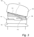
- An opposite end 116 of the link 110 may also be separated from the ridge 118 by a space. In some embodiments as shown in Figures 1 , 2 and 3 , the opposite end edge 116 may be inclined or curved. In other embodiments as shown in Figure 4 , the opposite end edge 116 is vertical.
- the bottom separation line 114 comprises a breakable bridge 400 ( Figure 4 ) under the opposite end 116.
- the breakable bridge 400 may be designed to secure the opposite end 116 of the link 110 when first applying the stopper 100 to the bottle (e.g., during manufacturing).
- the breakable bridge 400 is tom apart and separates when unscrewing the closure shell 102 (e.g., by a user opening the bottle), releasing the opposite end 116 of the link 110.
- the link 110 may be attached to the closure shell 102 through at least one of the bridges 108 which does not break when unscrewing the closure shell 102, relative to the other bridges 108 which are torn and broken when unscrewing the closure shell 102. So when the bottle is opened, the opposite end of the link 110 remains attached to the closure shell through the at least one remaining bridge 112. The remaining bridge 112 is shown in Figures 2 and 3 after opening the bottle.
- the remaining bridge 112 is configured to retain connection between the link 110 and the bottom edge of the closure 102.
- the remining bridge 112 be integrally formed (e.g., during molding) as a part of the link 110.
- the remaining bridge 112 is formed independent from the link 110 and subsequently attached to the link 110 (e.g., during a manufacturing operation).
- multiple remaining bridges 112 are not broken and are still attached at the link opposite end to the closure shell 102.
- the additional remaining bridge is located diametrically opposed to the remaining bridge 112 (i.e., 180° opposite of the remaining bridge 112).
- the remaining bridges 112 have a greater thickness and/or cross-sectional area relative to the other breakable bridges 108.
- the thickness and/or the cross-sectional area of the remaining bridges 112 is at least 30% greater than the respective thickness and cross-sectional area of the normal bridges 108.
- the thickness and/or the cross-sectional area of the remaining bridges 112 is 150% or 200% of the section of the normal bridges 108.
- the bridges 108 and/or the remaining bridges 112 have a square or rectangular shape, so the section of the remaining bridges 112 has a length and/or a width greater than the length and/or width of the bridges 108.
- the bridges 108 and/or the remaining bridges 112 have a circular or cylindrical or conical shape, so the section of the remaining bridges 112 has a diameter greater than the diameter of the bridges 108.
- the cross-sectional shape of the bridge 108 differs from the cross-sectional shape of the remaining bridges 112.
Landscapes
- Engineering & Computer Science (AREA)
- Mechanical Engineering (AREA)
- Closures For Containers (AREA)
Claims (2)
- Bouchon à vis en plastique solidaire (100), comprenant :une coque de fermeture (102) ;une bande d'inviolabilité (104) reliée à la coque de fermeture (102) par une pluralité de ponts (108) qui relient un bord inférieur de la coque de fermeture (102) à un bord supérieur de la bande d'inviolabilité (104) ; etune nervure (118) formant une liaison (110) qui relie de façon séparable la coque de fermeture (102) et la bande d'inviolabilité (104) par une ligne de faiblesse (106) contenant une pluralité de premiers ponts (108) et au moins un deuxième pont (112), l'au moins un deuxième pont (112) ayant une surface de section transversale supérieure à la surface de section transversale des premiers ponts (108),la liaison (110) étant formée par une ligne de séparation (114, 115) réalisée le long de la partie inférieure de la liaison (110) et de la partie supérieure du matériau restant de la bande d'inviolabilité (104), la liaison (110) restant attachée à la bande d'inviolabilité (104) par l'au moins un deuxième pont (112) lorsque la pluralité de premiers ponts (108) est rompue, etcaractérisé en ce qu'il y a au moins deux deuxièmes ponts (112) diamétralement opposés, chacun étant conçu pour rester attaché à la coque de fermeture (102) et permettre à la liaison (110) de rester attachée à la bande d'inviolabilité (104).
- Bouchon à vis en plastique solidaire (100) selon la revendication 1, la surface de section transversale du deuxième pont (112) étant 30 % supérieure à la surface de section transversale des premiers ponts (108).
Priority Applications (1)
| Application Number | Priority Date | Filing Date | Title |
|---|---|---|---|
| EP24207256.9A EP4470935A3 (fr) | 2018-11-04 | 2019-11-04 | Bouchon à vis en plastique attaché |
Applications Claiming Priority (2)
| Application Number | Priority Date | Filing Date | Title |
|---|---|---|---|
| US201862755501P | 2018-11-04 | 2018-11-04 | |
| PCT/US2019/059712 WO2020093062A2 (fr) | 2018-11-04 | 2019-11-04 | Bouchon à vis en plastique attaché |
Related Child Applications (2)
| Application Number | Title | Priority Date | Filing Date |
|---|---|---|---|
| EP24207256.9A Division EP4470935A3 (fr) | 2018-11-04 | 2019-11-04 | Bouchon à vis en plastique attaché |
| EP24207256.9A Division-Into EP4470935A3 (fr) | 2018-11-04 | 2019-11-04 | Bouchon à vis en plastique attaché |
Publications (3)
| Publication Number | Publication Date |
|---|---|
| EP3877280A2 EP3877280A2 (fr) | 2021-09-15 |
| EP3877280A4 EP3877280A4 (fr) | 2022-09-21 |
| EP3877280B1 true EP3877280B1 (fr) | 2025-01-01 |
Family
ID=70462875
Family Applications (2)
| Application Number | Title | Priority Date | Filing Date |
|---|---|---|---|
| EP24207256.9A Pending EP4470935A3 (fr) | 2018-11-04 | 2019-11-04 | Bouchon à vis en plastique attaché |
| EP19880856.0A Active EP3877280B1 (fr) | 2018-11-04 | 2019-11-04 | Bouchon à vis en plastique attaché |
Family Applications Before (1)
| Application Number | Title | Priority Date | Filing Date |
|---|---|---|---|
| EP24207256.9A Pending EP4470935A3 (fr) | 2018-11-04 | 2019-11-04 | Bouchon à vis en plastique attaché |
Country Status (5)
| Country | Link |
|---|---|
| US (2) | US11807436B2 (fr) |
| EP (2) | EP4470935A3 (fr) |
| CA (1) | CA3111594A1 (fr) |
| MX (1) | MX2021003757A (fr) |
| WO (1) | WO2020093062A2 (fr) |
Families Citing this family (5)
| Publication number | Priority date | Publication date | Assignee | Title |
|---|---|---|---|---|
| US11312544B2 (en) * | 2020-03-30 | 2022-04-26 | ThisCap, Inc. | Cap for container |
| MX2021001474A (es) * | 2018-08-14 | 2021-04-28 | Novembal Usa Inc | Anillo de transporte de botella con bloqueo para tapon. |
| CH718712A1 (de) * | 2021-06-07 | 2022-12-15 | Alpla Werke Alwin Lehner Gmbh & Co Kg | Unverlierbare Verschlusskappe. |
| US11975889B2 (en) * | 2021-09-02 | 2024-05-07 | Merrilee Kick | Container apparatus |
| IT202100029978A1 (it) * | 2021-11-26 | 2023-05-26 | Guala Pack Spa | Chiusura per una cannuccia di un imballo flessibile a pareti sottili |
Family Cites Families (16)
| Publication number | Priority date | Publication date | Assignee | Title |
|---|---|---|---|---|
| FR2329536A1 (fr) * | 1973-07-02 | 1977-05-27 | Somepla Sa | Nouvelle capsule a vis inviolable et imperdable |
| FR2499519A1 (fr) * | 1981-02-11 | 1982-08-13 | Grussen Jean | Capsule de bouchage a vis avec anneau d'inviolabilite |
| EP0107680B1 (fr) * | 1982-04-23 | 1986-01-29 | Cebal | Capsule de bouchage a vis, en plastique, a bande d'inviolabilite perfectionnee |
| GB8319444D0 (en) | 1983-07-19 | 1983-08-17 | Nat Plastics Ltd | Container closure |
| US4805792A (en) * | 1984-04-17 | 1989-02-21 | Continental White Cap, Inc. | Litterless tamper indicating closure |
| US5215204A (en) | 1992-03-09 | 1993-06-01 | Creative Packaging Corp. | Tamper evident closure with hinged band |
| JP3256344B2 (ja) * | 1993-07-21 | 2002-02-12 | 日本山村硝子株式会社 | ピルファープルーフキャップ |
| US5725115A (en) * | 1995-02-21 | 1998-03-10 | Crown Cork Ag | Closure cap with tether |
| IT1300020B1 (it) | 1998-05-08 | 2000-04-04 | Sacmi | Capsula a vite in materiale plastico con anello di garanzia. |
| US7789254B2 (en) | 2004-10-29 | 2010-09-07 | Novelis Inc. | Snap-top closure device |
| FR2923172B1 (fr) | 2007-11-06 | 2009-12-11 | Tetra Laval Holdings & Finance | Procede et machine de fabrication d'un bouchon pour un col de recipient, ainsi que bouchon tel qu'obtenu par ce procede |
| WO2010004919A1 (fr) * | 2008-07-08 | 2010-01-14 | 日本クラウンコルク株式会社 | Couvercle de contenant en résine synthétique |
| FR2937016B1 (fr) | 2008-10-09 | 2010-11-26 | Tetra Laval Holdings & Finance | Bouchon a ligne d'affaiblissement decoupee et procede de fabrication de ce bouchon |
| US8720716B2 (en) * | 2009-06-25 | 2014-05-13 | Phillip John Campbell | Closure with spring loaded tether docking |
| US10836549B2 (en) * | 2015-04-02 | 2020-11-17 | Thiscap Inc. | Cap for container |
| US10654625B2 (en) * | 2018-10-12 | 2020-05-19 | Closure Systems International Inc. | Twist and flip lock closure |
-
2019
- 2019-11-04 EP EP24207256.9A patent/EP4470935A3/fr active Pending
- 2019-11-04 EP EP19880856.0A patent/EP3877280B1/fr active Active
- 2019-11-04 MX MX2021003757A patent/MX2021003757A/es unknown
- 2019-11-04 WO PCT/US2019/059712 patent/WO2020093062A2/fr not_active Ceased
- 2019-11-04 CA CA3111594A patent/CA3111594A1/fr active Pending
- 2019-11-04 US US17/290,949 patent/US11807436B2/en active Active
-
2023
- 2023-11-03 US US18/501,325 patent/US20240067423A1/en not_active Abandoned
Also Published As
| Publication number | Publication date |
|---|---|
| MX2021003757A (es) | 2021-05-27 |
| EP3877280A4 (fr) | 2022-09-21 |
| US20240067423A1 (en) | 2024-02-29 |
| EP4470935A2 (fr) | 2024-12-04 |
| WO2020093062A3 (fr) | 2020-07-30 |
| US11807436B2 (en) | 2023-11-07 |
| CA3111594A1 (fr) | 2020-05-07 |
| EP4470935A3 (fr) | 2025-03-05 |
| EP3877280A2 (fr) | 2021-09-15 |
| WO2020093062A2 (fr) | 2020-05-07 |
| US20210387778A1 (en) | 2021-12-16 |
Similar Documents
| Publication | Publication Date | Title |
|---|---|---|
| EP3877279B1 (fr) | Bouchon à vis en plastique attaché | |
| EP3877280B1 (fr) | Bouchon à vis en plastique attaché | |
| EP3837186B1 (fr) | Bande de fixation d'un bouchon sur un anneau de transport d'une bouteille | |
| US5397009A (en) | Break-away safety cap for containers | |
| US20220048681A1 (en) | Tethered plastic stopper | |
| EP3880575B1 (fr) | Bouchon à vis en plastique attaché | |
| WO2020041640A1 (fr) | Bouchon attaché et procédé de fabrication associé | |
| US20210316908A1 (en) | Tethered plastic stopper | |
| WO2021074726A1 (fr) | Bouchon à vis en plastique attaché | |
| WO2020047557A1 (fr) | Bouchon en plastique attaché | |
| WO2021074727A1 (fr) | Fermeture en plastique dotée d'une attache | |
| WO2021074728A1 (fr) | Bouchon à vis en plastique attaché | |
| EP3853141B1 (fr) | Bouchon en plastique attaché | |
| US20230056087A1 (en) | Hinged stopper | |
| US11613412B2 (en) | Tethered plastic stopper | |
| RU2783612C1 (ru) | Крышка для закрытия емкости | |
| HK1186445B (en) | Receptacle for containing two different products separately and for mixing thereof |
Legal Events
| Date | Code | Title | Description |
|---|---|---|---|
| STAA | Information on the status of an ep patent application or granted ep patent |
Free format text: STATUS: THE INTERNATIONAL PUBLICATION HAS BEEN MADE |
|
| PUAI | Public reference made under article 153(3) epc to a published international application that has entered the european phase |
Free format text: ORIGINAL CODE: 0009012 |
|
| STAA | Information on the status of an ep patent application or granted ep patent |
Free format text: STATUS: REQUEST FOR EXAMINATION WAS MADE |
|
| 17P | Request for examination filed |
Effective date: 20210407 |
|
| AK | Designated contracting states |
Kind code of ref document: A2 Designated state(s): AL AT BE BG CH CY CZ DE DK EE ES FI FR GB GR HR HU IE IS IT LI LT LU LV MC MK MT NL NO PL PT RO RS SE SI SK SM TR |
|
| DAV | Request for validation of the european patent (deleted) | ||
| DAX | Request for extension of the european patent (deleted) | ||
| A4 | Supplementary search report drawn up and despatched |
Effective date: 20220824 |
|
| RIC1 | Information provided on ipc code assigned before grant |
Ipc: B65D 41/34 20060101AFI20220818BHEP |
|
| GRAP | Despatch of communication of intention to grant a patent |
Free format text: ORIGINAL CODE: EPIDOSNIGR1 |
|
| STAA | Information on the status of an ep patent application or granted ep patent |
Free format text: STATUS: GRANT OF PATENT IS INTENDED |
|
| INTG | Intention to grant announced |
Effective date: 20240618 |
|
| GRAS | Grant fee paid |
Free format text: ORIGINAL CODE: EPIDOSNIGR3 |
|
| RAP1 | Party data changed (applicant data changed or rights of an application transferred) |
Owner name: SIDEL PARTICIPATIONS SAS |
|
| GRAA | (expected) grant |
Free format text: ORIGINAL CODE: 0009210 |
|
| STAA | Information on the status of an ep patent application or granted ep patent |
Free format text: STATUS: THE PATENT HAS BEEN GRANTED |
|
| AK | Designated contracting states |
Kind code of ref document: B1 Designated state(s): AL AT BE BG CH CY CZ DE DK EE ES FI FR GB GR HR HU IE IS IT LI LT LU LV MC MK MT NL NO PL PT RO RS SE SI SK SM TR |
|
| REG | Reference to a national code |
Ref country code: GB Ref legal event code: FG4D |
|
| REG | Reference to a national code |
Ref country code: CH Ref legal event code: EP |
|
| REG | Reference to a national code |
Ref country code: DE Ref legal event code: R096 Ref document number: 602019064415 Country of ref document: DE |
|
| REG | Reference to a national code |
Ref country code: IE Ref legal event code: FG4D |
|
| P01 | Opt-out of the competence of the unified patent court (upc) registered |
Free format text: CASE NUMBER: APP_565/2025 Effective date: 20250107 |
|
| REG | Reference to a national code |
Ref country code: LT Ref legal event code: MG9D |
|
| REG | Reference to a national code |
Ref country code: NL Ref legal event code: MP Effective date: 20250101 |
|
| REG | Reference to a national code |
Ref country code: AT Ref legal event code: MK05 Ref document number: 1756036 Country of ref document: AT Kind code of ref document: T Effective date: 20250101 |
|
| PG25 | Lapsed in a contracting state [announced via postgrant information from national office to epo] |
Ref country code: NL Free format text: LAPSE BECAUSE OF FAILURE TO SUBMIT A TRANSLATION OF THE DESCRIPTION OR TO PAY THE FEE WITHIN THE PRESCRIBED TIME-LIMIT Effective date: 20250101 |
|
| PG25 | Lapsed in a contracting state [announced via postgrant information from national office to epo] |
Ref country code: FI Free format text: LAPSE BECAUSE OF FAILURE TO SUBMIT A TRANSLATION OF THE DESCRIPTION OR TO PAY THE FEE WITHIN THE PRESCRIBED TIME-LIMIT Effective date: 20250101 |
|
| PG25 | Lapsed in a contracting state [announced via postgrant information from national office to epo] |
Ref country code: PL Free format text: LAPSE BECAUSE OF FAILURE TO SUBMIT A TRANSLATION OF THE DESCRIPTION OR TO PAY THE FEE WITHIN THE PRESCRIBED TIME-LIMIT Effective date: 20250101 |
|
| PG25 | Lapsed in a contracting state [announced via postgrant information from national office to epo] |
Ref country code: ES Free format text: LAPSE BECAUSE OF FAILURE TO SUBMIT A TRANSLATION OF THE DESCRIPTION OR TO PAY THE FEE WITHIN THE PRESCRIBED TIME-LIMIT Effective date: 20250101 |
|
| PG25 | Lapsed in a contracting state [announced via postgrant information from national office to epo] |
Ref country code: NO Free format text: LAPSE BECAUSE OF FAILURE TO SUBMIT A TRANSLATION OF THE DESCRIPTION OR TO PAY THE FEE WITHIN THE PRESCRIBED TIME-LIMIT Effective date: 20250401 Ref country code: IS Free format text: LAPSE BECAUSE OF FAILURE TO SUBMIT A TRANSLATION OF THE DESCRIPTION OR TO PAY THE FEE WITHIN THE PRESCRIBED TIME-LIMIT Effective date: 20250501 |
|
| PG25 | Lapsed in a contracting state [announced via postgrant information from national office to epo] |
Ref country code: HR Free format text: LAPSE BECAUSE OF FAILURE TO SUBMIT A TRANSLATION OF THE DESCRIPTION OR TO PAY THE FEE WITHIN THE PRESCRIBED TIME-LIMIT Effective date: 20250101 |
|
| PG25 | Lapsed in a contracting state [announced via postgrant information from national office to epo] |
Ref country code: LV Free format text: LAPSE BECAUSE OF FAILURE TO SUBMIT A TRANSLATION OF THE DESCRIPTION OR TO PAY THE FEE WITHIN THE PRESCRIBED TIME-LIMIT Effective date: 20250101 Ref country code: PT Free format text: LAPSE BECAUSE OF FAILURE TO SUBMIT A TRANSLATION OF THE DESCRIPTION OR TO PAY THE FEE WITHIN THE PRESCRIBED TIME-LIMIT Effective date: 20250502 |
|
| PG25 | Lapsed in a contracting state [announced via postgrant information from national office to epo] |
Ref country code: GR Free format text: LAPSE BECAUSE OF FAILURE TO SUBMIT A TRANSLATION OF THE DESCRIPTION OR TO PAY THE FEE WITHIN THE PRESCRIBED TIME-LIMIT Effective date: 20250402 Ref country code: BG Free format text: LAPSE BECAUSE OF FAILURE TO SUBMIT A TRANSLATION OF THE DESCRIPTION OR TO PAY THE FEE WITHIN THE PRESCRIBED TIME-LIMIT Effective date: 20250101 |
|
| PG25 | Lapsed in a contracting state [announced via postgrant information from national office to epo] |
Ref country code: AT Free format text: LAPSE BECAUSE OF FAILURE TO SUBMIT A TRANSLATION OF THE DESCRIPTION OR TO PAY THE FEE WITHIN THE PRESCRIBED TIME-LIMIT Effective date: 20250101 |
|
| PG25 | Lapsed in a contracting state [announced via postgrant information from national office to epo] |
Ref country code: CZ Free format text: LAPSE BECAUSE OF FAILURE TO SUBMIT A TRANSLATION OF THE DESCRIPTION OR TO PAY THE FEE WITHIN THE PRESCRIBED TIME-LIMIT Effective date: 20250101 |
|
| PG25 | Lapsed in a contracting state [announced via postgrant information from national office to epo] |
Ref country code: SE Free format text: LAPSE BECAUSE OF FAILURE TO SUBMIT A TRANSLATION OF THE DESCRIPTION OR TO PAY THE FEE WITHIN THE PRESCRIBED TIME-LIMIT Effective date: 20250101 |
|
| REG | Reference to a national code |
Ref country code: DE Ref legal event code: R097 Ref document number: 602019064415 Country of ref document: DE |
|
| PG25 | Lapsed in a contracting state [announced via postgrant information from national office to epo] |
Ref country code: SM Free format text: LAPSE BECAUSE OF FAILURE TO SUBMIT A TRANSLATION OF THE DESCRIPTION OR TO PAY THE FEE WITHIN THE PRESCRIBED TIME-LIMIT Effective date: 20250101 |
|
| PG25 | Lapsed in a contracting state [announced via postgrant information from national office to epo] |
Ref country code: DK Free format text: LAPSE BECAUSE OF FAILURE TO SUBMIT A TRANSLATION OF THE DESCRIPTION OR TO PAY THE FEE WITHIN THE PRESCRIBED TIME-LIMIT Effective date: 20250101 |
|
| PG25 | Lapsed in a contracting state [announced via postgrant information from national office to epo] |
Ref country code: IT Free format text: LAPSE BECAUSE OF FAILURE TO SUBMIT A TRANSLATION OF THE DESCRIPTION OR TO PAY THE FEE WITHIN THE PRESCRIBED TIME-LIMIT Effective date: 20250101 |
|
| PG25 | Lapsed in a contracting state [announced via postgrant information from national office to epo] |
Ref country code: EE Free format text: LAPSE BECAUSE OF FAILURE TO SUBMIT A TRANSLATION OF THE DESCRIPTION OR TO PAY THE FEE WITHIN THE PRESCRIBED TIME-LIMIT Effective date: 20250101 |
|
| PG25 | Lapsed in a contracting state [announced via postgrant information from national office to epo] |
Ref country code: RO Free format text: LAPSE BECAUSE OF FAILURE TO SUBMIT A TRANSLATION OF THE DESCRIPTION OR TO PAY THE FEE WITHIN THE PRESCRIBED TIME-LIMIT Effective date: 20250101 |
|
| PG25 | Lapsed in a contracting state [announced via postgrant information from national office to epo] |
Ref country code: SK Free format text: LAPSE BECAUSE OF FAILURE TO SUBMIT A TRANSLATION OF THE DESCRIPTION OR TO PAY THE FEE WITHIN THE PRESCRIBED TIME-LIMIT Effective date: 20250101 |
|
| PLBE | No opposition filed within time limit |
Free format text: ORIGINAL CODE: 0009261 |
|
| STAA | Information on the status of an ep patent application or granted ep patent |
Free format text: STATUS: NO OPPOSITION FILED WITHIN TIME LIMIT |
|
| 26N | No opposition filed |
Effective date: 20251002 |