EP3877304B1 - Dispositif de dosage de produits en vrac - Google Patents
Dispositif de dosage de produits en vrac Download PDFInfo
- Publication number
- EP3877304B1 EP3877304B1 EP19808989.8A EP19808989A EP3877304B1 EP 3877304 B1 EP3877304 B1 EP 3877304B1 EP 19808989 A EP19808989 A EP 19808989A EP 3877304 B1 EP3877304 B1 EP 3877304B1
- Authority
- EP
- European Patent Office
- Prior art keywords
- bulk material
- screw
- conveying
- metering
- materials according
- Prior art date
- Legal status (The legal status is an assumption and is not a legal conclusion. Google has not performed a legal analysis and makes no representation as to the accuracy of the status listed.)
- Active
Links
Images


Classifications
-
- B—PERFORMING OPERATIONS; TRANSPORTING
- B65—CONVEYING; PACKING; STORING; HANDLING THIN OR FILAMENTARY MATERIAL
- B65G—TRANSPORT OR STORAGE DEVICES, e.g. CONVEYORS FOR LOADING OR TIPPING, SHOP CONVEYOR SYSTEMS OR PNEUMATIC TUBE CONVEYORS
- B65G33/00—Screw or rotary spiral conveyors
- B65G33/08—Screw or rotary spiral conveyors for fluent solid materials
- B65G33/14—Screw or rotary spiral conveyors for fluent solid materials comprising a screw or screws enclosed in a tubular housing
- B65G33/18—Screw or rotary spiral conveyors for fluent solid materials comprising a screw or screws enclosed in a tubular housing with multiple screws in parallel arrangements, e.g. concentric
-
- G—PHYSICS
- G01—MEASURING; TESTING
- G01F—MEASURING VOLUME, VOLUME FLOW, MASS FLOW OR LIQUID LEVEL; METERING BY VOLUME
- G01F11/00—Apparatus requiring external operation adapted at each repeated and identical operation to measure and separate a predetermined volume of fluid or fluent solid material from a supply or container, without regard to weight, and to deliver it
- G01F11/10—Apparatus requiring external operation adapted at each repeated and identical operation to measure and separate a predetermined volume of fluid or fluent solid material from a supply or container, without regard to weight, and to deliver it with measuring chambers moved during operation
- G01F11/12—Apparatus requiring external operation adapted at each repeated and identical operation to measure and separate a predetermined volume of fluid or fluent solid material from a supply or container, without regard to weight, and to deliver it with measuring chambers moved during operation of the valve type, i.e. the separating being effected by fluid-tight or powder-tight movements
- G01F11/20—Apparatus requiring external operation adapted at each repeated and identical operation to measure and separate a predetermined volume of fluid or fluent solid material from a supply or container, without regard to weight, and to deliver it with measuring chambers moved during operation of the valve type, i.e. the separating being effected by fluid-tight or powder-tight movements wherein the measuring chamber rotates or oscillates
- G01F11/24—Apparatus requiring external operation adapted at each repeated and identical operation to measure and separate a predetermined volume of fluid or fluent solid material from a supply or container, without regard to weight, and to deliver it with measuring chambers moved during operation of the valve type, i.e. the separating being effected by fluid-tight or powder-tight movements wherein the measuring chamber rotates or oscillates for fluent solid material
Definitions
- the invention relates to a device for dosing bulk materials according to the preamble of claim 1, in particular a dosing device for solids, essentially consisting of product storage and continuous product conveyance, namely a material-friendly, high-precision powder dosing device for demanding applications, e.g. for the pharmaceutical industry, special chemicals.
- the paver includes two augers and baffles located above the augers.
- the guide plates which are called bulk material screens in the present application, cover the screws in the longitudinal direction and not in the transverse direction. They also do not extend over the entire width of the respective screw conveyor.
- a dosing device of an agricultural distribution machine contains several screw conveyors and also guide plates, i.e. bulk material screens, which do not cover the screw conveyors, but are arranged perpendicular to the longitudinal axis of the screw conveyors and transverse to the conveying direction.
- EA CHOICE US2800252 EA CHOICE US3151782, GEA WO2013182869, Hess US3212624, Kardux US4945957, KTron US20070170209A1, Schenck DE102007055566B4, Schenck DE102010009753B4, Schenck EP1220804B1, Schenck EP1401747B1, Schenck EP1954610B1, Vibra Screw US5154326, VibraScrew US5937996 .
- the invention achieves the following advantages, among others: Advantage a: The residence time distribution of the product volume in the feeder is reduced.
- section A-A The mass flow (section A-A) is made possible by the asymmetrical screw trough (4), the bulk material screens (10), the three screw conveyors (6), and the vibration of this entire structure: vibration drive(s) (7)
- Vibration drives are all available machines that generate vibrations or impulses, such as magnetic exciters, knockers, ball vibrators, unbalance motors or directional exciters.
- screw types / modular structure three screws, 2 screws, 1 screw, 2-, 3- and 4-flight screws, Concave screws, spiral screws, intermeshing screws, self-cleaning screws, co-rotating screws, counter-rotating screws.
- Second is: first-in-first-out / mass flow / low residence time distribution
- the mass flow here is synonymous with first-in-first-out and is synonymous with low residence time distribution.
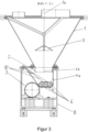
- the drawing shows a dosing device as it corresponds to the invention with the conical bulk material template (1), which sits on a housing (8) (not mandatory), the drive (5) and the screw tube (9). Other components are covered by the housing (8).
- the lines from A to A and from B to B define the visual axes of the figures 1 and 2 .
- the screens (10) form three staggered levels with the asymmetrical trough (4) (see also Figures 3 , 5 , 6 , 7 ), which gradually release the screw conveyors (6) in the direction of production (11) for the bulk material flowing thereon.
- the screw conveyors (6) are set in rotation by a drive with a gear or multiple drives (5).
- the screw conveyors (6) convey the bulk material out of the dosing device through the screw tube (9).
- the bulk material discharge plate (3) releases an annular gap for the bulk material.
- the bulk material relief plate prevents the bulk material from being compressed and further contributes to the activation of the bulk material and allows the mass flow in the bulk material receiver (1).
- the activation is generated by the vibration drive (7).
- the resulting movement activates the bulk material ( Principle: micro throw / see manual dosing, Gerhard Vetter, publisher: Vulkan Verlag Dec 2001, 2001, ISBN 10: 3802721993 / ISBN 13: 9783802721991 ).
- the outlet from the product receiver (2) is designed asymmetrically. See also figure 1 and the distance between the axes (1a) and (1b).
- the asymmetry aids the flow of bridging bulk materials and is an important part of the invention.
- a bulk product bridge is easiest to set up when the opposing supports on which the bridge ends rest are symmetrical. Due to the symmetry, the load of the upper part of the bulk material can be supported on the bottom layer of the bulk material, which is at the height of the supports. Due to the symmetry, the load is distributed evenly and the bulk material bridge can solidify. With asymmetrical supports, it is not possible to distribute the load evenly. As a result, the bulk material bridge that is being built up collapses again.
- the screw conveyors (6) here are each 2-flight concave screws meshing with one another.
- 4- and 3-flight intermeshing concave worms (not prior art) and spiral worms (prior art) are used.
- the 4- and 3-flight, intermeshing concave screws have several bulk material ejection flanks per revolution. As a result, an advantageous reduction in pulsation compared to the prior art can be achieved at low speeds.
- FIG. 5 - 7 is the area in the asymmetric screw trough (4).
- the bulk material screen (10) partially covers the augers (6).
- the screws (6) are gradually released, so that bulk material (17) is transported by the screws (6) in the direction of production (11).
- This detail is an essential part of the invention. Due to the geometry, the number of screws (6) and the screens, a mass flow is achieved in the area of the asymmetric screw trough (4); cf.
- FIG. 5 In the cone-shaped bulk material receiver, the bulk material level decreases during the dosing process, in principle as shown by lines (13) and (14). The almost parallel course of the two lines (13), (14) is characteristic of the mass flow. Lines (13), (14) are examples of the mass flow principle described. According to this principle, the bulk material flows in every point of the dosing device; from highest to lowest point, snails (6).
- the conical bulk material template is filled with the bulk material (15) in normal dosing operation. There is a free volume (16) below the bulk material discharge plate (3).
- a snail (6) is covered in this area by the built-in bulk material screen (10). As a result, the screw (6) is not filled with the bulk material (17) at this point.
- the built-in bulk material screen (10) covers two screws (6) in this area. As a result, the screws (6) are not filled with the bulk material (17) at this point.
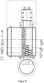
- the screw tube is designed differently.
- the augers are not flush with the pipe but are retracted. This results in a small storage area.
- the product-specific distance "X" between the screw 6 and the screw tube 9 results in an advantageous reduction in pulsation.
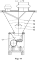
- Figures 9 to 12 show an alternative embodiment according to the invention with fixtures in the trough on the steep trough side.
- the device is built mirror-symmetrically, taking into account the function of the individual components.
- the screens are not provided on the sloping wall, but on the vertical wall.
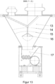
- Figures 13 to 14 Fig. 12 show another alternative embodiment according to the invention, wherein the method part is mirrored.
- the device is built mirror-symmetrically, taking into account the function of the individual components.
- the vertical wall of the screw trough is swapped with the sloping wall.
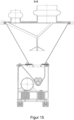
- FIGS 15 to 19 show further alternative embodiments according to the invention, here with various screw variations.
- the snails in the drawings "looking in front of the head", no longer lie as in figure 3 on an imaginary horizontal line, but are arranged, for example, in a sloping / tilted line ( Figures 16 to 19 ) or they are eg arranged in a V, in other words, the middle of three snails is offset downwards.
Landscapes
- Physics & Mathematics (AREA)
- Fluid Mechanics (AREA)
- General Physics & Mathematics (AREA)
- Engineering & Computer Science (AREA)
- Mechanical Engineering (AREA)
- Screw Conveyors (AREA)
- Filling Or Emptying Of Bunkers, Hoppers, And Tanks (AREA)
Claims (11)
- Dispositif permettant le dosage de produits en vrac comportant une entrée dans la région supérieure et comportant plusieurs vis sans fin (6), le dispositif présentant des obturateurs de produit en vrac (10) au-dessus des vis sans fin (6), les vis sans fin (6) étant divisées en différentes régions et les différentes régions des vis sans fin (6) étant recouvertes par les obturateurs de produit en vrac (10), les régions recouvertes étant réalisées en tant que zones s'étendant transversalement à l'axe longitudinal des vis sans fin (6), caractérisé en ce qu'une première vis sans fin n'est pas recouverte par les obturateurs de produit en vrac, la région arrière de la deuxième vis sans fin adjacente est recouverte par les obturateurs de produit en vrac et, dans le cas d'une troisième vis sans fin adjacente à la deuxième vis sans fin, toutes les régions sont recouvertes, à l'exception de la région avant.
- Dispositif permettant le dosage de produits en vrac selon la revendication 1, caractérisé en ce que les zones s'étendant transversalement à l'axe longitudinal des vis sans fin (6) s'étendent sur toute la largeur de la vis sans fin (6) respective.
- Dispositif permettant le dosage de produits en vrac selon la revendication 1, caractérisé en ce que les régions avant des vis sans fin (6) ne sont pas recouvertes par les obturateurs de produit en vrac (10).
- Dispositif permettant le dosage de produits en vrac selon la revendication 1, caractérisé en ce que les obturateurs de produit en vrac (10) sont disposés obliquement vers le bas en direction des vis sans fin (6).
- Dispositif permettant le dosage de produits en vrac selon la revendication 1, caractérisé en ce que les vis sans fin (6) sont disposées horizontalement côte à côte.
- Dispositif permettant le dosage de produits en vrac selon la revendication 1, caractérisé en ce que les vis sans fin (6) viennent en prise les unes dans les autres.
- Dispositif permettant le dosage de produits en vrac selon la revendication 1, caractérisé en ce qu'une première vis sans fin extérieure n'est pas du tout recouverte par les obturateurs de produit en vrac (10) et les vis sans fin adjacentes sont progressivement recouvertes de plus en plus, les recouvrements comprenant toujours la région arrière des vis sans fin et la vis sans fin la plus éloignée de la première vis sans fin (6) étant complètement recouverte, à l'exception d'une région avant.
- Dispositif permettant le dosage de produits en vrac selon la revendication 1, caractérisé en ce que le dispositif présente une alimentation en produit en vrac (1) et en ce que la sortie (2) de l'alimentation en produit en vrac (1) est disposée dans la région des extrémités avant des vis sans fin (6).
- Dispositif permettant le dosage de produits en vrac selon la revendication 1, caractérisé en ce que le dispositif est réalisé sous la forme d'un doseur à vis à vibrations.
- Dispositif permettant le dosage de produits en vrac selon la revendication 1, caractérisé en ce que toutes les parties en contact avec le produit vibrent pendant le fonctionnement.
- Dispositif permettant le dosage de produits en vrac selon la revendication 1, caractérisé en ce que l'alimentation en produit en vrac conique du dispositif et/ou l'actionneur de décharge de produit en vrac du dispositif et/ou le logement de vis du dispositif et/ou les vis sans fin du dispositif et/ou le tube de vis du dispositif et/ou les obturateurs de produit en vrac du dispositif vibrent pendant le fonctionnement.
Applications Claiming Priority (2)
| Application Number | Priority Date | Filing Date | Title |
|---|---|---|---|
| DE102018128043.2A DE102018128043A1 (de) | 2018-11-09 | 2018-11-09 | Vorrichtung zum Dosieren von Schüttgütern |
| PCT/EP2019/080165 WO2020094605A1 (fr) | 2018-11-09 | 2019-11-05 | Dispositif de dosage de produits en vrac |
Publications (3)
| Publication Number | Publication Date |
|---|---|
| EP3877304A1 EP3877304A1 (fr) | 2021-09-15 |
| EP3877304C0 EP3877304C0 (fr) | 2023-06-07 |
| EP3877304B1 true EP3877304B1 (fr) | 2023-06-07 |
Family
ID=68655493
Family Applications (1)
| Application Number | Title | Priority Date | Filing Date |
|---|---|---|---|
| EP19808989.8A Active EP3877304B1 (fr) | 2018-11-09 | 2019-11-05 | Dispositif de dosage de produits en vrac |
Country Status (3)
| Country | Link |
|---|---|
| EP (1) | EP3877304B1 (fr) |
| DE (1) | DE102018128043A1 (fr) |
| WO (1) | WO2020094605A1 (fr) |
Families Citing this family (1)
| Publication number | Priority date | Publication date | Assignee | Title |
|---|---|---|---|---|
| DE102019114927A1 (de) | 2019-06-04 | 2020-12-10 | Brabender Technologie Gmbh & Co. Kg | Vorrichtung zum gravimetrischen Dosieren von Schüttgütern |
Family Cites Families (22)
| Publication number | Priority date | Publication date | Assignee | Title |
|---|---|---|---|---|
| US2800252A (en) | 1954-03-17 | 1957-07-23 | Eugene A Wahl | Powder-feeding apparatus |
| FR1326933A (fr) * | 1961-06-29 | 1963-05-10 | Danske Sukkerfab | Dispositif pour la lixiviation continue de matières divisées ou broyées, de préférence d'origine végétale ou animale |
| US3151782A (en) | 1962-03-20 | 1964-10-06 | Eugene A Wahl | Material feeder having vibratory means |
| DE1409835A1 (de) * | 1962-09-21 | 1969-08-28 | Martin Rausch | Zusatzeinrichtung fuer Foerderschnecken von bevorzugt fahrbaren Streuvorrichtungen |
| US3212624A (en) | 1963-11-26 | 1965-10-19 | Carrier Mfg Co | Vibratory screw feeder |
| US4368833A (en) * | 1981-06-08 | 1983-01-18 | Werner & Pfleiderer Corporation | Anti-bridging port for co-rotational screw machine |
| AT384198B (de) * | 1984-11-30 | 1987-10-12 | Oetiker Hans Maschinen | Foerdervorrichtung fuer schuettgut |
| US4945957A (en) | 1988-05-02 | 1990-08-07 | Ohaus Corporation | High-resolution weigher/feeder for fine particulate materials |
| US5154326A (en) | 1991-03-07 | 1992-10-13 | Gain Lab Corporation | Vibrator and screw combined conveying device used in weighing of powder |
| US5937996A (en) | 1998-01-13 | 1999-08-17 | Vibrascrew Inc. | Vibrating screw feeder |
| DE19912689A1 (de) * | 1999-03-20 | 2000-09-21 | Schwaebische Huettenwerke Gmbh | Austrageeinheit für Schüttgutbunker |
| DE19947516A1 (de) | 1999-10-01 | 2001-04-05 | Schenck Process Gmbh | Dosiervorrichtung für Schüttgüter |
| DE10126232A1 (de) | 2001-05-30 | 2002-12-12 | Schenck Process Gmbh | Dosiervorrichtung |
| US6976819B2 (en) * | 2003-04-16 | 2005-12-20 | Del Corporation | Tank having multiple screw-type transfer augers |
| DE202004002601U1 (de) | 2004-02-13 | 2004-04-22 | K-Tron (Switzerland) Ltd. | Vorrichtung zum Dosieren von Schüttgütern mit einem Rührwerk und einer Antriebseinheit |
| DE102005053352B4 (de) | 2005-11-07 | 2008-01-10 | Schenck Process Gmbh | Vorrichtung zur dosierten Entnahme von Schüttgut |
| DE102007055566B4 (de) | 2007-11-20 | 2012-10-11 | Schenck Process Gmbh | Dosierwaage für Schüttgut |
| DE102010009753B4 (de) | 2010-03-01 | 2014-09-18 | Schenck Process Gmbh | Vorrichtung und Verfahren zur Dosierregelung von Schüttgut |
| DE102010050490A1 (de) * | 2010-06-25 | 2011-12-29 | Dynapac Gmbh | Verfahren zur Herstellung eines Straßenbelags, Beschicker, Straßenfertiger und Einbauzug |
| IN2014DN11260A (fr) | 2012-06-04 | 2015-10-09 | Gea Process Engineering Nv | |
| EP2799619A3 (fr) * | 2013-04-12 | 2015-04-01 | ASTEC Mobile Machinery GmbH | Réservoir de mélange et de réserve et procédé d'homogénéisation de matériau dans un tel réservoir de mélange et de réserve |
| DE102015118355A1 (de) * | 2015-10-27 | 2017-04-27 | Lemken Gmbh & Co. Kg | Dosiereinrichtung einer landwirtschaftlichen Verteilmaschine |
-
2018
- 2018-11-09 DE DE102018128043.2A patent/DE102018128043A1/de not_active Withdrawn
-
2019
- 2019-11-05 EP EP19808989.8A patent/EP3877304B1/fr active Active
- 2019-11-05 WO PCT/EP2019/080165 patent/WO2020094605A1/fr not_active Ceased
Also Published As
| Publication number | Publication date |
|---|---|
| DE102018128043A1 (de) | 2020-05-14 |
| EP3877304C0 (fr) | 2023-06-07 |
| WO2020094605A1 (fr) | 2020-05-14 |
| EP3877304A1 (fr) | 2021-09-15 |
Similar Documents
| Publication | Publication Date | Title |
|---|---|---|
| DE202016002402U1 (de) | Zuführeinrichtung, Siebeinrichtung und Fördereinrichtung | |
| EP3877304B1 (fr) | Dispositif de dosage de produits en vrac | |
| DE2621256A1 (de) | Aufgabetrichter | |
| EP0112398B1 (fr) | Dispositif de dosage | |
| EP0468399A2 (fr) | Dispositif pour le dosage et/ou le mélange continu, pneumatique gravimetrique de marchandises en vrac | |
| DE3233416C2 (fr) | ||
| EP4180777B1 (fr) | Dispositif de pesage et de transport et procédé de transport et de détection du débit massique de produits en vrac | |
| EP0189468B1 (fr) | Installation pour l'introduction de matieres solides fractionnees et amenees en continu dans une machine de traitement | |
| EP2375226B1 (fr) | Dispositif de dosage gravimétrique de marchandises en vrac | |
| EP3065883B1 (fr) | Dispositif permettant de disperser des produits pulvérulents sur la surface de nappes de matière | |
| DE19720143C2 (de) | Silo | |
| DE4400029C2 (de) | Vorrichtung für eine regelbare dosierte Förderung von staub- und granulatförmigen Schüttgütern, bei konstantem Druck | |
| EP3980733B1 (fr) | Dispositif de dosage gravimétrique de produits en vrac | |
| DE102019134920B4 (de) | Aktivierungsmittel für Dosiervorrichtung | |
| EP3904221A1 (fr) | Dispositif de dosage et procédé de fonctionnement un dispositif de dosage | |
| EP3053862A2 (fr) | Procede de dosage et dispositif de dosage pour particules en vrac | |
| AT389687B (de) | Foerderkanal fuer pulver- oder kornfoermige materialien | |
| EP1574462B1 (fr) | Dispositif de dosage | |
| EP4168336B1 (fr) | Dispositif doté d'un générateur d'ultrasons et procédé de fonctionnement | |
| EP3445480B1 (fr) | Dispositif de dosage de matières solides, notamment de matière fibreuses | |
| DE102013206322A1 (de) | Fördervorrichtung für Schüttgut | |
| EP4241565A1 (fr) | Dispositif d'alimentation en pâte avec section transversale de passage localement restreinte | |
| DE19521766A1 (de) | Verfahren und Vorrichtung zur Auflösung von Schüttgutstopfen | |
| EP4667092A1 (fr) | Dispositif pour mélanger et/ou conditionner des matériaux pulvérulents et procédé pour faire fonctionner ce dispositif | |
| EP0135919A2 (fr) | Procédé de réunion de composantes granuleux et dispositif d'exécution d'un tel procédé |
Legal Events
| Date | Code | Title | Description |
|---|---|---|---|
| STAA | Information on the status of an ep patent application or granted ep patent |
Free format text: STATUS: UNKNOWN |
|
| STAA | Information on the status of an ep patent application or granted ep patent |
Free format text: STATUS: THE INTERNATIONAL PUBLICATION HAS BEEN MADE |
|
| PUAI | Public reference made under article 153(3) epc to a published international application that has entered the european phase |
Free format text: ORIGINAL CODE: 0009012 |
|
| STAA | Information on the status of an ep patent application or granted ep patent |
Free format text: STATUS: REQUEST FOR EXAMINATION WAS MADE |
|
| 17P | Request for examination filed |
Effective date: 20210326 |
|
| AK | Designated contracting states |
Kind code of ref document: A1 Designated state(s): AL AT BE BG CH CY CZ DE DK EE ES FI FR GB GR HR HU IE IS IT LI LT LU LV MC MK MT NL NO PL PT RO RS SE SI SK SM TR |
|
| DAV | Request for validation of the european patent (deleted) | ||
| DAX | Request for extension of the european patent (deleted) | ||
| GRAP | Despatch of communication of intention to grant a patent |
Free format text: ORIGINAL CODE: EPIDOSNIGR1 |
|
| STAA | Information on the status of an ep patent application or granted ep patent |
Free format text: STATUS: GRANT OF PATENT IS INTENDED |
|
| RIC1 | Information provided on ipc code assigned before grant |
Ipc: G01F 11/24 20060101ALI20220927BHEP Ipc: B65G 33/18 20060101AFI20220927BHEP |
|
| INTG | Intention to grant announced |
Effective date: 20221027 |
|
| GRAS | Grant fee paid |
Free format text: ORIGINAL CODE: EPIDOSNIGR3 |
|
| RAP1 | Party data changed (applicant data changed or rights of an application transferred) |
Owner name: KUBOTA BRABENDER TECHNOLOGIE GMBH |
|
| GRAA | (expected) grant |
Free format text: ORIGINAL CODE: 0009210 |
|
| STAA | Information on the status of an ep patent application or granted ep patent |
Free format text: STATUS: THE PATENT HAS BEEN GRANTED |
|
| AK | Designated contracting states |
Kind code of ref document: B1 Designated state(s): AL AT BE BG CH CY CZ DE DK EE ES FI FR GB GR HR HU IE IS IT LI LT LU LV MC MK MT NL NO PL PT RO RS SE SI SK SM TR |
|
| REG | Reference to a national code |
Ref country code: GB Ref legal event code: FG4D Free format text: NOT ENGLISH |
|
| REG | Reference to a national code |
Ref country code: CH Ref legal event code: EP Ref country code: AT Ref legal event code: REF Ref document number: 1574441 Country of ref document: AT Kind code of ref document: T Effective date: 20230615 |
|
| REG | Reference to a national code |
Ref country code: DE Ref legal event code: R096 Ref document number: 502019008126 Country of ref document: DE |
|
| U01 | Request for unitary effect filed |
Effective date: 20230612 |
|
| U07 | Unitary effect registered |
Designated state(s): AT BE BG DE DK EE FI FR IT LT LU LV MT NL PT SE SI Effective date: 20230710 |
|
| REG | Reference to a national code |
Ref country code: LT Ref legal event code: MG9D |
|
| PG25 | Lapsed in a contracting state [announced via postgrant information from national office to epo] |
Ref country code: NO Free format text: LAPSE BECAUSE OF FAILURE TO SUBMIT A TRANSLATION OF THE DESCRIPTION OR TO PAY THE FEE WITHIN THE PRESCRIBED TIME-LIMIT Effective date: 20230907 Ref country code: ES Free format text: LAPSE BECAUSE OF FAILURE TO SUBMIT A TRANSLATION OF THE DESCRIPTION OR TO PAY THE FEE WITHIN THE PRESCRIBED TIME-LIMIT Effective date: 20230607 |
|
| PG25 | Lapsed in a contracting state [announced via postgrant information from national office to epo] |
Ref country code: RS Free format text: LAPSE BECAUSE OF FAILURE TO SUBMIT A TRANSLATION OF THE DESCRIPTION OR TO PAY THE FEE WITHIN THE PRESCRIBED TIME-LIMIT Effective date: 20230607 Ref country code: HR Free format text: LAPSE BECAUSE OF FAILURE TO SUBMIT A TRANSLATION OF THE DESCRIPTION OR TO PAY THE FEE WITHIN THE PRESCRIBED TIME-LIMIT Effective date: 20230607 Ref country code: GR Free format text: LAPSE BECAUSE OF FAILURE TO SUBMIT A TRANSLATION OF THE DESCRIPTION OR TO PAY THE FEE WITHIN THE PRESCRIBED TIME-LIMIT Effective date: 20230908 |
|
| PG25 | Lapsed in a contracting state [announced via postgrant information from national office to epo] |
Ref country code: SK Free format text: LAPSE BECAUSE OF FAILURE TO SUBMIT A TRANSLATION OF THE DESCRIPTION OR TO PAY THE FEE WITHIN THE PRESCRIBED TIME-LIMIT Effective date: 20230607 |
|
| PG25 | Lapsed in a contracting state [announced via postgrant information from national office to epo] |
Ref country code: IS Free format text: LAPSE BECAUSE OF FAILURE TO SUBMIT A TRANSLATION OF THE DESCRIPTION OR TO PAY THE FEE WITHIN THE PRESCRIBED TIME-LIMIT Effective date: 20231007 |
|
| PG25 | Lapsed in a contracting state [announced via postgrant information from national office to epo] |
Ref country code: SM Free format text: LAPSE BECAUSE OF FAILURE TO SUBMIT A TRANSLATION OF THE DESCRIPTION OR TO PAY THE FEE WITHIN THE PRESCRIBED TIME-LIMIT Effective date: 20230607 Ref country code: SK Free format text: LAPSE BECAUSE OF FAILURE TO SUBMIT A TRANSLATION OF THE DESCRIPTION OR TO PAY THE FEE WITHIN THE PRESCRIBED TIME-LIMIT Effective date: 20230607 Ref country code: RO Free format text: LAPSE BECAUSE OF FAILURE TO SUBMIT A TRANSLATION OF THE DESCRIPTION OR TO PAY THE FEE WITHIN THE PRESCRIBED TIME-LIMIT Effective date: 20230607 Ref country code: IS Free format text: LAPSE BECAUSE OF FAILURE TO SUBMIT A TRANSLATION OF THE DESCRIPTION OR TO PAY THE FEE WITHIN THE PRESCRIBED TIME-LIMIT Effective date: 20231007 Ref country code: CZ Free format text: LAPSE BECAUSE OF FAILURE TO SUBMIT A TRANSLATION OF THE DESCRIPTION OR TO PAY THE FEE WITHIN THE PRESCRIBED TIME-LIMIT Effective date: 20230607 |
|
| PG25 | Lapsed in a contracting state [announced via postgrant information from national office to epo] |
Ref country code: PL Free format text: LAPSE BECAUSE OF FAILURE TO SUBMIT A TRANSLATION OF THE DESCRIPTION OR TO PAY THE FEE WITHIN THE PRESCRIBED TIME-LIMIT Effective date: 20230607 |
|
| REG | Reference to a national code |
Ref country code: DE Ref legal event code: R097 Ref document number: 502019008126 Country of ref document: DE |
|
| PLBE | No opposition filed within time limit |
Free format text: ORIGINAL CODE: 0009261 |
|
| STAA | Information on the status of an ep patent application or granted ep patent |
Free format text: STATUS: NO OPPOSITION FILED WITHIN TIME LIMIT |
|
| 26N | No opposition filed |
Effective date: 20240308 |
|
| REG | Reference to a national code |
Ref country code: CH Ref legal event code: PL |
|
| PG25 | Lapsed in a contracting state [announced via postgrant information from national office to epo] |
Ref country code: MC Free format text: LAPSE BECAUSE OF FAILURE TO SUBMIT A TRANSLATION OF THE DESCRIPTION OR TO PAY THE FEE WITHIN THE PRESCRIBED TIME-LIMIT Effective date: 20230607 |
|
| U90 | Renewal fees not paid: noting of loss of rights |
Free format text: RENEWAL FEE NOT PAID FOR YEAR 05 Effective date: 20240614 |
|
| PG25 | Lapsed in a contracting state [announced via postgrant information from national office to epo] |
Ref country code: CH Free format text: LAPSE BECAUSE OF NON-PAYMENT OF DUE FEES Effective date: 20231130 |
|
| GBPC | Gb: european patent ceased through non-payment of renewal fee |
Effective date: 20231105 |
|
| PG25 | Lapsed in a contracting state [announced via postgrant information from national office to epo] |
Ref country code: MC Free format text: LAPSE BECAUSE OF FAILURE TO SUBMIT A TRANSLATION OF THE DESCRIPTION OR TO PAY THE FEE WITHIN THE PRESCRIBED TIME-LIMIT Effective date: 20230607 Ref country code: CH Free format text: LAPSE BECAUSE OF NON-PAYMENT OF DUE FEES Effective date: 20231130 |
|
| REG | Reference to a national code |
Ref country code: IE Ref legal event code: MM4A |
|
| PG25 | Lapsed in a contracting state [announced via postgrant information from national office to epo] |
Ref country code: IE Free format text: LAPSE BECAUSE OF NON-PAYMENT OF DUE FEES Effective date: 20231105 |
|
| PG25 | Lapsed in a contracting state [announced via postgrant information from national office to epo] |
Ref country code: GB Free format text: LAPSE BECAUSE OF NON-PAYMENT OF DUE FEES Effective date: 20231105 |
|
| U93 | Unitary patent lapsed |
Free format text: RENEWAL FEE NOT PAID Effective date: 20231130 |
|
| PG25 | Lapsed in a contracting state [announced via postgrant information from national office to epo] |
Ref country code: IE Free format text: LAPSE BECAUSE OF NON-PAYMENT OF DUE FEES Effective date: 20231105 Ref country code: GB Free format text: LAPSE BECAUSE OF NON-PAYMENT OF DUE FEES Effective date: 20231105 |
|
| PG25 | Lapsed in a contracting state [announced via postgrant information from national office to epo] |
Ref country code: CY Free format text: LAPSE BECAUSE OF FAILURE TO SUBMIT A TRANSLATION OF THE DESCRIPTION OR TO PAY THE FEE WITHIN THE PRESCRIBED TIME-LIMIT; INVALID AB INITIO Effective date: 20191105 |
|
| PG25 | Lapsed in a contracting state [announced via postgrant information from national office to epo] |
Ref country code: HU Free format text: LAPSE BECAUSE OF FAILURE TO SUBMIT A TRANSLATION OF THE DESCRIPTION OR TO PAY THE FEE WITHIN THE PRESCRIBED TIME-LIMIT; INVALID AB INITIO Effective date: 20191105 |
|
| PG25 | Lapsed in a contracting state [announced via postgrant information from national office to epo] |
Ref country code: TR Free format text: LAPSE BECAUSE OF FAILURE TO SUBMIT A TRANSLATION OF THE DESCRIPTION OR TO PAY THE FEE WITHIN THE PRESCRIBED TIME-LIMIT Effective date: 20230607 |