EP3877323B1 - Selbstentlüftender ventilverschluss - Google Patents
Selbstentlüftender ventilverschluss Download PDFInfo
- Publication number
- EP3877323B1 EP3877323B1 EP19820843.1A EP19820843A EP3877323B1 EP 3877323 B1 EP3877323 B1 EP 3877323B1 EP 19820843 A EP19820843 A EP 19820843A EP 3877323 B1 EP3877323 B1 EP 3877323B1
- Authority
- EP
- European Patent Office
- Prior art keywords
- valve
- detent
- valve member
- valve closure
- closure
- Prior art date
- Legal status (The legal status is an assumption and is not a legal conclusion. Google has not performed a legal analysis and makes no representation as to the accuracy of the status listed.)
- Active
Links
Images




Classifications
-
- B—PERFORMING OPERATIONS; TRANSPORTING
- B67—OPENING, CLOSING OR CLEANING BOTTLES, JARS OR SIMILAR CONTAINERS; LIQUID HANDLING
- B67D—DISPENSING, DELIVERING OR TRANSFERRING LIQUIDS, NOT OTHERWISE PROVIDED FOR
- B67D1/00—Apparatus or devices for dispensing beverages on draught
- B67D1/08—Details
- B67D1/0829—Keg connection means
- B67D1/0831—Keg connection means combined with valves
- B67D1/0832—Keg connection means combined with valves with two valves disposed concentrically
-
- B—PERFORMING OPERATIONS; TRANSPORTING
- B67—OPENING, CLOSING OR CLEANING BOTTLES, JARS OR SIMILAR CONTAINERS; LIQUID HANDLING
- B67D—DISPENSING, DELIVERING OR TRANSFERRING LIQUIDS, NOT OTHERWISE PROVIDED FOR
- B67D1/00—Apparatus or devices for dispensing beverages on draught
- B67D1/08—Details
- B67D1/0829—Keg connection means
- B67D1/0831—Keg connection means combined with valves
-
- B—PERFORMING OPERATIONS; TRANSPORTING
- B67—OPENING, CLOSING OR CLEANING BOTTLES, JARS OR SIMILAR CONTAINERS; LIQUID HANDLING
- B67D—DISPENSING, DELIVERING OR TRANSFERRING LIQUIDS, NOT OTHERWISE PROVIDED FOR
- B67D1/00—Apparatus or devices for dispensing beverages on draught
- B67D1/08—Details
- B67D1/0829—Keg connection means
- B67D1/0831—Keg connection means combined with valves
- B67D1/0835—Keg connection means combined with valves with one valve
-
- B—PERFORMING OPERATIONS; TRANSPORTING
- B67—OPENING, CLOSING OR CLEANING BOTTLES, JARS OR SIMILAR CONTAINERS; LIQUID HANDLING
- B67D—DISPENSING, DELIVERING OR TRANSFERRING LIQUIDS, NOT OTHERWISE PROVIDED FOR
- B67D1/00—Apparatus or devices for dispensing beverages on draught
- B67D1/08—Details
- B67D1/0829—Keg connection means
- B67D1/0841—Details
- B67D1/0845—Security means
-
- B—PERFORMING OPERATIONS; TRANSPORTING
- B67—OPENING, CLOSING OR CLEANING BOTTLES, JARS OR SIMILAR CONTAINERS; LIQUID HANDLING
- B67D—DISPENSING, DELIVERING OR TRANSFERRING LIQUIDS, NOT OTHERWISE PROVIDED FOR
- B67D1/00—Apparatus or devices for dispensing beverages on draught
- B67D1/08—Details
- B67D1/0829—Keg connection means
- B67D1/0841—Details
- B67D1/0849—Details provided with means to open the keg valve when gas pressure is applied to it
-
- B—PERFORMING OPERATIONS; TRANSPORTING
- B67—OPENING, CLOSING OR CLEANING BOTTLES, JARS OR SIMILAR CONTAINERS; LIQUID HANDLING
- B67D—DISPENSING, DELIVERING OR TRANSFERRING LIQUIDS, NOT OTHERWISE PROVIDED FOR
- B67D1/00—Apparatus or devices for dispensing beverages on draught
- B67D1/08—Details
- B67D1/0878—Safety, warning or controlling devices
-
- B—PERFORMING OPERATIONS; TRANSPORTING
- B67—OPENING, CLOSING OR CLEANING BOTTLES, JARS OR SIMILAR CONTAINERS; LIQUID HANDLING
- B67D—DISPENSING, DELIVERING OR TRANSFERRING LIQUIDS, NOT OTHERWISE PROVIDED FOR
- B67D7/00—Apparatus or devices for transferring liquids from bulk storage containers or reservoirs into vehicles or into portable containers, e.g. for retail sale purposes
- B67D7/06—Details or accessories
- B67D7/32—Arrangements of safety or warning devices; Means for preventing unauthorised delivery of liquid
Definitions
- This invention relates to closures which incorporate valves.
- Such closures are used with liquid containers such as beer kegs and are configured to enable the liquid contents to be dispensed by gas pressure.
- Kegs containing carbonated beverages are, due to the nature of carbonated beverages, under internal pressure. This pressure is dependent on the level of carbonation (amount of dissolved CO 2 ) and the temperature of the beverage.
- a gas is introduced into the keg under pressure in order to displace the contents.
- Such kegs normally have a closure incorporating a twin valve arrangement which facilitates the simultaneous introduction of the dispense gas and extraction of the beverage.
- These valves also provide access for filling the keg with beverage and they normally open and close both paths upon connection and disconnection. It is vital that these valves are fully closed after the beverage has been introduced so as not to lose carbonation.
- the pressure of gas used to dispense must be greater than the equilibrium pressure of the dissolved CO 2 so that the level of carbonation is maintained throughout the dispense process. Dispensing is usually considered complete after all of the beverage has been extracted. However, for various reasons a keg may sometimes be left with some residual beverage, when the shelf life of the product has expired for example.
- the dispense gas After dispensing, the dispense gas remains inside the keg under the same pressure as used for the dispense. This is undesirable as a keg under pressure may pose a threat to safety during a later recycling or disposal process. It is therefore desirable that this pressure is released after dispensing is complete.
- valve closure with a deformable seal is disclosed in DE 10 2018 053716 A1 .
- Valve closures exist which automatically latch the valve in an open position when the valve is operated during dispense, but the closures incorporate extra moving parts which increase the size and complexity of the closure.
- a common form of valve closure is known as an A-type valve, which is also similar to a G-type valve. Both have a fixed central core pin and a single spring-loaded valve member which controls two ports. When engaged with a suitable valve-operating member, gas can be fed into the container past the outer periphery of the valve element while beer simultaneously flows out of the container past the inner periphery of the element.
- Other forms of valve closure are also used with beer kegs.
- S, D and M types are similar to each other in that they all have no fixed central core pin but have two concentric spring-loaded moving valve members which separately control the two ports.
- the valve members are operated by respective spring elements, but the valve members may be cascaded such that closure of one spring-loaded valve member causes closure of the other.
- the present invention proposes a valve closure according to claim 1.
- the invention also provides a valve closure having a valve member (6) which is rotatable to move a retainer (34) which is operable to hold a detent (23) in an inoperative position.
- the invention also provides a valve closure having a detent (23) carried by a resiliently deflectable arm (22) which extends circumferentially about a rotatable valve member (6), and a retainer (34) carried by the valve member holds the detent (23) in the inoperative position by engagement with the resiliently deflectable arm.
- the invention also provides a valve closure in combination with a rotating tool to engage and rotate a valve member (6).
- valve closure shown in the drawings is of the kind known as an A-type valve. All components of the valve closure may be moulded of polymeric materials (plastics) so that the closure is fully recyclable.
- a preferred form of valve closure is described in EP 2 585 400 A1 .
- the valve closure V comprises a closure body 1 which is adapted to be fitted onto the neck N of a beverage container C such as a beer keg, which is typically formed by stretch blow moulding.
- the closure body has an annular top wall 2 which is concentric with a fixed disc-shaped cap 3 formed at the upper end of a hollow core pin 4.
- a valve member 6 includes a resilient seal 7 and is spring-loaded by a compression spring 8 which sealingly urges the valve member against an outer valve seat 9 formed around the inner periphery of the annular top wall 2 and an inner valve seat 10 formed around the periphery of the cap 3.
- a cylindrical valve-operating member M as in Fig.
- valve member 6 is depressed against its spring-loading and makes sealing contact with the valve-operating member M to provide separate gas and liquid flow paths past the valve-operating member, indicated by the broken arrows G and L respectively.
- Pressurised gas is fed into the container C through a gas inlet port 11. Liquid simultaneously flows out of the container through a draw tube 14 and the core pin 4, exiting through a liquid dispensing port 12.
- valve member 6 Normally, when dispensing is finished and the valve-operating member M is disconnected, the valve member 6 returns to the sealing condition shown in Fig. 1 , holding the internal gas pressure within the container together with any residual liquid.
- the present valve closure incorporates a self-venting mechanism for automatically venting any residual dispensing gas after use so that the keg is no longer under pressure whilst maintaining a fully sealed state after initial keg manufacture and filling.
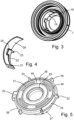
- the closure body 1 contains a shallow part-circumferential internal recess 18 which contains a venting member 19.
- the venting member is disposed opposite the outer periphery of the valve member 6, which has been omitted from the drawing for clarity.
- the venting member 19, shown separately in Fig. 4 may be integrally moulded to include a curved wall 20 with a stop 21 at one end. Adjacent to the stop 21 a curved resiliently deflectable spring arm 22 extends inwardly towards the valve member 6, carrying an inwardly-projecting tongue which forms a detent 23 at the free end of the spring arm.
- the curved wall 20 contains a recess 24 which allows the spring arm 22 to be depressed in an outward direction without being impeded by the wall 20.
- the valve member 6 is rotatably mounted within the closure body.
- the valve member has an annular sealing wall 26 which is integrally formed with an axially-extending cylindrical portion 27.
- the sealing wall 26 has a sealing face 28, remote from the cylindrical portion 27, which includes an inner sealing bead 29 for sealing contact with the cap 3, an intermediate sealing bead 40 for sealing contact with the valve operating member M ( Fig. 2 ), and an outer sealing bead 30 for sealing contact with the annular wall 2.
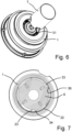
- the top face 28 contains slots 31 which may be engaged by a suitable tool in order to rotate the valve member, such as the castellated tool T (e.g. a filling head) shown in Fig. 6 .
- the outer periphery of the sealing wall 26 has an axially extending side face 32 which carries a number of radial projections 33.
- the radial projections 33 generally guide the valve member for smooth axial movement under the action of the spring 8.
- One of the radial projections 34 acts as an axially-extending retainer 34.
- the valve member 6 can be rotated to an inoperative position (clockwise as shown) which is determined by engagement of one or more of the projections 33 with stop projections 36 on the interior of the closure body 1.
- the retainer 34 When The retainer 34 is located opposite the free end of the spring arm 22 as shown, the retainer depresses the spring arm radially outwards into the recess 24 holding the venting member 19 inoperative.
- the valve member 6 is free to slide axially within the closure body, e.g. when the valve is opened during filling, but the axial extent of the retainer 34 is sufficient to hold the spring arm 22 within the recess 24.
- the valve re-closes, e.g. on disconnection of the filling head, the detent 23 does not impede closure of the valve member 6, which can return to the sealing position, fully closing both of the flow paths G and L. The valve closure can thus be opened and re-closed as required as long as the valve member remains in this rotational position.
- Fig. 8 shows the valve member 6 rotated into an operative condition, which may, for example, be carried out by the filling head after closure of the valve or by a separate tool following disconnection of the filling head and before delivery to the end user.
- the rotational position of the valve member 6 (anti-clockwise as shown) is again determined by engagement of projections 33 with stop projections 36 on the interior of the closure body 1.
- the retainer 34 is now located at the root of the spring arm 22 allowing the spring arm to move radially inwards until the detent 23 contacts the side face 32 of the valve member, as shown in Fig. 9 .
- valve member 6 is again free to slide axially within the closure body when the valve is opened to dispense the product, but once the valve is fully opened the detent 23 is permitted to move between the sealing face of the valve member and the annular top wall 2, overlying the outer bead 30 as shown in Fig. 10 .
- the detent 23 interferes with the sealing action of the outer sealing bead 30, seen in Fig. 11 , allowing the dispensing gas to slowly vent from the container.
- the tongue-like detent 23 is able to distort, thereby limiting it's effect on final resting position of the valve member 6.
- the size and shape of the detent 23 determines the amount of seal interference thus regulating the rate of pressure loss when the valve is closed. It is generally desirable that the rate of pressure loss is relatively slow, typically taking several minutes to fully vent the dispensing gas. Activation of the venting member would not therefore prevent a keg being moved between dispensing positions within a short period, for example.
- FIG. 12 A modified tool for manually rotating the valve member 6 within the closure body 1 is shown in Fig. 12 .
- the top face of the valve member again contains a ring of circumferential slots 31 between the outer sealing bead and the exposed intermediate sealing bead 40, but in this case the slots are closely spaced to allow rapid engagement.
- the tool T is generally cylindrical with indentations 46 for manually gripping and rotating the tool.
- the opposite end of the tool has a ring of circumferentially-arranged teeth 42, with axially-extending leading edges and inclined trailing edges, which enables the teeth to drivably engage within the the slots 31.
- valve closure described herein maintains an effective seal after filling but automatically vents the dispensing gas after dispense is complete.
- the venting mechanism can be activated after the keg has been filled and with the valve closed. This mechanism, when activated, primes a spring loaded arm that interferes with the normal sealing of the dispensing gas port when the valve is next operated, i.e. connected for dispensing. When the mechanism is not activated it does not interfere with the normal sealing function and opening and closing of the valve can be carried out as normal.
- the party filling the keg can choose whether or not to activate the automatic venting function after filling.
- the venting mechanism can be applied to the dispensing gas valve in all the common valve formats A, G, S, D and M types.
Landscapes
- Engineering & Computer Science (AREA)
- Mechanical Engineering (AREA)
- Devices For Dispensing Beverages (AREA)
- Filling Of Jars Or Cans And Processes For Cleaning And Sealing Jars (AREA)
Claims (7)
- Ein Ventilverschluss:- ein Verschlusskörper (1) zur Befestigung an einem Behälter,- eine Gaseinlassöffnung (11),- eine Flüssigkeitsabgabeöffnung (12),- Ventilmittel zum dichten Verschließen der Gaseinlass- und Flüssigkeitsabgabeöffnungen, wobei die Ventilmittel ein axial bewegliches Ventilelement (6) mit einer Dichtfläche (28) umfassen, die mit einem durch eine ringförmige Wand (2) gebildeten Ventilsitz (9) zusammenwirken kann, um die Gaseinlassöffnung dicht zu verschließen;- eine Sperrklinke (23), die in eine Entlüftungsposition bewegbar ist, in der die Sperrklinke verhindert, dass die Ventilmittel (6) die Gaseinlassöffnung dicht verschließen;
dadurch gekennzeichnet, dass die Sperrklinke (23) von einem Arm (22) getragen wird, der sich kreisförmig um das Ventilelement (6) erstreckt, wobei der Arm (22) elastisch auslenkbar ist, um die Sperrklinke (23) in Richtung der Entlüftungsposition zu bewegen, und wobei die Sperrklinke (23) in der Entlüftungsposition zwischen der Dichtfläche (28) und dem Ventilsitz (9) angeordnet ist. - Ein Ventilverschluss nach Anspruch 1, wobei das Ventilelement (6) eine Seitenfläche (32) aufweist, die mit einem Halter (34) versehen ist, der die Sperrklinke (23) während des Öffnens und Schließens der Gaseinlassöffnung (11) in einer inaktiven Position halten kann.
- Ein Ventilverschluss nach Anspruch 2, wobei das Ventilelement (6) drehbar ist, um den Halter (34) aus der inaktiven Position zu bewegen.
- Ein Ventilverschluss nach Anspruch 3, wobei die Sperrklinke (23) von einem elastisch ablenkbaren Arm (22) getragen wird, der sich kreisförmig um das Ventilelement (6) erstreckt, und der Halter (34) die Sperrklinke (23) durch Eingriff mit dem elastisch ablenkbaren Arm in der Ruhestellung hält.
- Ein Ventilverschluss nach Anspruch 3, wobei die Dichtfläche (28) des Ventilelements kreisförmige Schlitze (31) zum Eingriff durch ein rotierendes Werkzeug aufweist.
- Ein Ventilverschluss nach Anspruch 3 in Kombination mit einem rotierenden Werkzeug, das mit Mitteln zum Eingriff und Drehen des Ventilelements (6) versehen ist.
- Ein Behälter, der mit einem Ventilverschluss nach Anspruch 1 versehen ist.
Applications Claiming Priority (2)
| Application Number | Priority Date | Filing Date | Title |
|---|---|---|---|
| GB1818330.1A GB2578881B (en) | 2018-11-09 | 2018-11-09 | Self venting valve closure |
| PCT/GB2019/053158 WO2020095054A1 (en) | 2018-11-09 | 2019-11-08 | Self venting valve closure |
Publications (2)
| Publication Number | Publication Date |
|---|---|
| EP3877323A1 EP3877323A1 (de) | 2021-09-15 |
| EP3877323B1 true EP3877323B1 (de) | 2025-02-12 |
Family
ID=64739425
Family Applications (1)
| Application Number | Title | Priority Date | Filing Date |
|---|---|---|---|
| EP19820843.1A Active EP3877323B1 (de) | 2018-11-09 | 2019-11-08 | Selbstentlüftender ventilverschluss |
Country Status (4)
| Country | Link |
|---|---|
| US (1) | US20220002136A1 (de) |
| EP (1) | EP3877323B1 (de) |
| GB (1) | GB2578881B (de) |
| WO (1) | WO2020095054A1 (de) |
Families Citing this family (1)
| Publication number | Priority date | Publication date | Assignee | Title |
|---|---|---|---|---|
| JP7817692B2 (ja) * | 2021-11-25 | 2026-02-19 | アサヒビール株式会社 | 飲料容器、および、飲料容器の組立方法 |
Family Cites Families (15)
| Publication number | Priority date | Publication date | Assignee | Title |
|---|---|---|---|---|
| US4305421A (en) * | 1977-09-28 | 1981-12-15 | Draft Systems, Inc. | Fluid dispensing system |
| US4159102A (en) * | 1977-09-28 | 1979-06-26 | Draft Systems, Inc. | Locking mechanism for coupler and valve assembly |
| US4291821A (en) * | 1979-10-04 | 1981-09-29 | The Perlick Company, Inc. | Keg tapping system unit and valve interlock |
| GB2075476B (en) * | 1980-04-22 | 1983-12-07 | Alumasc Ltd | Valve-type closure for containers |
| US4350273A (en) * | 1980-06-27 | 1982-09-21 | The Perlick Company, Inc. | Portable keg tapping coupler |
| US4406301A (en) * | 1981-04-07 | 1983-09-27 | Vending Components, Inc. | Keg-tapping structure |
| US4538746A (en) * | 1983-06-29 | 1985-09-03 | Vending Components, Inc. | Keg-tapping assembly |
| DE3902527C1 (de) * | 1989-01-28 | 1990-06-21 | Joachim 7100 Heilbronn De Mogler | |
| US7686194B2 (en) * | 2003-09-03 | 2010-03-30 | Rieke Corporation | Closed loop fluid dispensing system |
| DE102008053716B4 (de) * | 2008-10-29 | 2012-09-27 | Khs Gmbh | Behälter, insbesondere großvolumiger Einwegbehälter aus Kunststoff wie beispielweise Keg zur Aufnahme von Getränken |
| GB201005994D0 (en) * | 2010-04-09 | 2010-05-26 | Petainer Lidkoeping Ab | Keg closure with safety mechanism |
| GB2481577A (en) | 2010-06-24 | 2012-01-04 | Silvia Romana Marabini | Valve closure for containers such as beer kegs |
| GB2485528B (en) * | 2010-11-09 | 2013-03-06 | Petainer Lidkoeping Ab | Keg closure with safety mechanism |
| GB2485529B (en) * | 2010-11-10 | 2013-03-06 | Petainer Lidkoeping Ab | Keg closure with safety mechanism |
| GB201307088D0 (en) * | 2013-04-19 | 2013-05-29 | Simpson Kenneth L | Valve-spear fitting for a keg |
-
2018
- 2018-11-09 GB GB1818330.1A patent/GB2578881B/en active Active
-
2019
- 2019-11-08 WO PCT/GB2019/053158 patent/WO2020095054A1/en not_active Ceased
- 2019-11-08 US US17/289,917 patent/US20220002136A1/en not_active Abandoned
- 2019-11-08 EP EP19820843.1A patent/EP3877323B1/de active Active
Also Published As
| Publication number | Publication date |
|---|---|
| WO2020095054A1 (en) | 2020-05-14 |
| GB201818330D0 (en) | 2018-12-26 |
| GB2578881A (en) | 2020-06-03 |
| US20220002136A1 (en) | 2022-01-06 |
| EP3877323A1 (de) | 2021-09-15 |
| GB2578881B (en) | 2022-10-12 |
Similar Documents
| Publication | Publication Date | Title |
|---|---|---|
| US4834271A (en) | One-piece dispensing closure | |
| US5158211A (en) | Fluid dispensing unit retainer | |
| EP3877321B1 (de) | Beutel-in-fass-behälter mit ventildichtlippe | |
| EP2080710A1 (de) | Montage eines Behälters und eines Verschlusses | |
| EP1027849A2 (de) | Trinkgefäss mit Deckel und Ausgiesstülle | |
| CN104955764B (zh) | 具有泄放机构的桶密封件 | |
| GB2182916A (en) | Hand-held dispenser with automatic cap venting | |
| AU2011237578A1 (en) | Keg closure with safety mechanism | |
| CN113165859A (zh) | 用于通过包括分配阀的分配管来分配饮料的套件 | |
| US6341721B1 (en) | Container closure | |
| EP1997746B1 (de) | Schließventil und Behälter damit | |
| US20220002136A1 (en) | Self venting valve closure | |
| US20250304337A1 (en) | Fluid Dispensing Closure Device for a Fluid Container | |
| US11358855B2 (en) | Valve closure incorporating an over-pressure relief valve | |
| WO2018056870A1 (ru) | Клапанная конструкция для пэт кега | |
| US4706855A (en) | One-piece container closure of the dispensing type | |
| EP3877324B1 (de) | Beutel-in-fass-behälter mit festdruck-prv | |
| EP3906211B1 (de) | Ventilverschluss mit konzentrischen federbelasteten tellern, wobei der innere teller axiale vorsprünge aufweist | |
| WO2000020326A1 (en) | Closure valves | |
| CA2919364C (en) | Closure for the charging hole of a liquid container | |
| US5094365A (en) | Adapter for use in tapping a container | |
| EP3877284B1 (de) | Behälter und verschluss mit rückschlagschutzkanälen | |
| CZ11194U1 (en) | Closure for carbonated drinks with discharge and pressure restoring means | |
| HK1030531A (en) | Beverage container with cap and spout |
Legal Events
| Date | Code | Title | Description |
|---|---|---|---|
| STAA | Information on the status of an ep patent application or granted ep patent |
Free format text: STATUS: UNKNOWN |
|
| STAA | Information on the status of an ep patent application or granted ep patent |
Free format text: STATUS: THE INTERNATIONAL PUBLICATION HAS BEEN MADE |
|
| PUAI | Public reference made under article 153(3) epc to a published international application that has entered the european phase |
Free format text: ORIGINAL CODE: 0009012 |
|
| STAA | Information on the status of an ep patent application or granted ep patent |
Free format text: STATUS: REQUEST FOR EXAMINATION WAS MADE |
|
| 17P | Request for examination filed |
Effective date: 20210526 |
|
| AK | Designated contracting states |
Kind code of ref document: A1 Designated state(s): AL AT BE BG CH CY CZ DE DK EE ES FI FR GB GR HR HU IE IS IT LI LT LU LV MC MK MT NL NO PL PT RO RS SE SI SK SM TR |
|
| DAV | Request for validation of the european patent (deleted) | ||
| DAX | Request for extension of the european patent (deleted) | ||
| GRAP | Despatch of communication of intention to grant a patent |
Free format text: ORIGINAL CODE: EPIDOSNIGR1 |
|
| STAA | Information on the status of an ep patent application or granted ep patent |
Free format text: STATUS: GRANT OF PATENT IS INTENDED |
|
| INTG | Intention to grant announced |
Effective date: 20240913 |
|
| GRAS | Grant fee paid |
Free format text: ORIGINAL CODE: EPIDOSNIGR3 |
|
| GRAA | (expected) grant |
Free format text: ORIGINAL CODE: 0009210 |
|
| STAA | Information on the status of an ep patent application or granted ep patent |
Free format text: STATUS: THE PATENT HAS BEEN GRANTED |
|
| AK | Designated contracting states |
Kind code of ref document: B1 Designated state(s): AL AT BE BG CH CY CZ DE DK EE ES FI FR GB GR HR HU IE IS IT LI LT LU LV MC MK MT NL NO PL PT RO RS SE SI SK SM TR |
|
| REG | Reference to a national code |
Ref country code: GB Ref legal event code: FG4D |
|
| REG | Reference to a national code |
Ref country code: CH Ref legal event code: EP |
|
| REG | Reference to a national code |
Ref country code: DE Ref legal event code: R096 Ref document number: 602019065868 Country of ref document: DE |
|
| REG | Reference to a national code |
Ref country code: IE Ref legal event code: FG4D |
|
| REG | Reference to a national code |
Ref country code: NL Ref legal event code: MP Effective date: 20250212 |
|
| PG25 | Lapsed in a contracting state [announced via postgrant information from national office to epo] |
Ref country code: RS Free format text: LAPSE BECAUSE OF FAILURE TO SUBMIT A TRANSLATION OF THE DESCRIPTION OR TO PAY THE FEE WITHIN THE PRESCRIBED TIME-LIMIT Effective date: 20250512 |
|
| PG25 | Lapsed in a contracting state [announced via postgrant information from national office to epo] |
Ref country code: FI Free format text: LAPSE BECAUSE OF FAILURE TO SUBMIT A TRANSLATION OF THE DESCRIPTION OR TO PAY THE FEE WITHIN THE PRESCRIBED TIME-LIMIT Effective date: 20250212 |
|
| PG25 | Lapsed in a contracting state [announced via postgrant information from national office to epo] |
Ref country code: PL Free format text: LAPSE BECAUSE OF FAILURE TO SUBMIT A TRANSLATION OF THE DESCRIPTION OR TO PAY THE FEE WITHIN THE PRESCRIBED TIME-LIMIT Effective date: 20250212 |
|
| PG25 | Lapsed in a contracting state [announced via postgrant information from national office to epo] |
Ref country code: ES Free format text: LAPSE BECAUSE OF FAILURE TO SUBMIT A TRANSLATION OF THE DESCRIPTION OR TO PAY THE FEE WITHIN THE PRESCRIBED TIME-LIMIT Effective date: 20250212 |
|
| REG | Reference to a national code |
Ref country code: LT Ref legal event code: MG9D |
|
| PG25 | Lapsed in a contracting state [announced via postgrant information from national office to epo] |
Ref country code: NO Free format text: LAPSE BECAUSE OF FAILURE TO SUBMIT A TRANSLATION OF THE DESCRIPTION OR TO PAY THE FEE WITHIN THE PRESCRIBED TIME-LIMIT Effective date: 20250512 Ref country code: IS Free format text: LAPSE BECAUSE OF FAILURE TO SUBMIT A TRANSLATION OF THE DESCRIPTION OR TO PAY THE FEE WITHIN THE PRESCRIBED TIME-LIMIT Effective date: 20250612 |
|
| PG25 | Lapsed in a contracting state [announced via postgrant information from national office to epo] |
Ref country code: NL Free format text: LAPSE BECAUSE OF FAILURE TO SUBMIT A TRANSLATION OF THE DESCRIPTION OR TO PAY THE FEE WITHIN THE PRESCRIBED TIME-LIMIT Effective date: 20250212 |
|
| PG25 | Lapsed in a contracting state [announced via postgrant information from national office to epo] |
Ref country code: HR Free format text: LAPSE BECAUSE OF FAILURE TO SUBMIT A TRANSLATION OF THE DESCRIPTION OR TO PAY THE FEE WITHIN THE PRESCRIBED TIME-LIMIT Effective date: 20250212 |
|
| PG25 | Lapsed in a contracting state [announced via postgrant information from national office to epo] |
Ref country code: PT Free format text: LAPSE BECAUSE OF FAILURE TO SUBMIT A TRANSLATION OF THE DESCRIPTION OR TO PAY THE FEE WITHIN THE PRESCRIBED TIME-LIMIT Effective date: 20250612 Ref country code: LV Free format text: LAPSE BECAUSE OF FAILURE TO SUBMIT A TRANSLATION OF THE DESCRIPTION OR TO PAY THE FEE WITHIN THE PRESCRIBED TIME-LIMIT Effective date: 20250212 |
|
| PG25 | Lapsed in a contracting state [announced via postgrant information from national office to epo] |
Ref country code: BG Free format text: LAPSE BECAUSE OF FAILURE TO SUBMIT A TRANSLATION OF THE DESCRIPTION OR TO PAY THE FEE WITHIN THE PRESCRIBED TIME-LIMIT Effective date: 20250212 Ref country code: GR Free format text: LAPSE BECAUSE OF FAILURE TO SUBMIT A TRANSLATION OF THE DESCRIPTION OR TO PAY THE FEE WITHIN THE PRESCRIBED TIME-LIMIT Effective date: 20250513 |
|
| REG | Reference to a national code |
Ref country code: AT Ref legal event code: MK05 Ref document number: 1765921 Country of ref document: AT Kind code of ref document: T Effective date: 20250212 |
|
| PG25 | Lapsed in a contracting state [announced via postgrant information from national office to epo] |
Ref country code: SE Free format text: LAPSE BECAUSE OF FAILURE TO SUBMIT A TRANSLATION OF THE DESCRIPTION OR TO PAY THE FEE WITHIN THE PRESCRIBED TIME-LIMIT Effective date: 20250212 |
|
| PG25 | Lapsed in a contracting state [announced via postgrant information from national office to epo] |
Ref country code: SM Free format text: LAPSE BECAUSE OF FAILURE TO SUBMIT A TRANSLATION OF THE DESCRIPTION OR TO PAY THE FEE WITHIN THE PRESCRIBED TIME-LIMIT Effective date: 20250212 |
|
| PG25 | Lapsed in a contracting state [announced via postgrant information from national office to epo] |
Ref country code: DK Free format text: LAPSE BECAUSE OF FAILURE TO SUBMIT A TRANSLATION OF THE DESCRIPTION OR TO PAY THE FEE WITHIN THE PRESCRIBED TIME-LIMIT Effective date: 20250212 |
|
| PG25 | Lapsed in a contracting state [announced via postgrant information from national office to epo] |
Ref country code: AT Free format text: LAPSE BECAUSE OF FAILURE TO SUBMIT A TRANSLATION OF THE DESCRIPTION OR TO PAY THE FEE WITHIN THE PRESCRIBED TIME-LIMIT Effective date: 20250212 |
|
| PG25 | Lapsed in a contracting state [announced via postgrant information from national office to epo] |
Ref country code: EE Free format text: LAPSE BECAUSE OF FAILURE TO SUBMIT A TRANSLATION OF THE DESCRIPTION OR TO PAY THE FEE WITHIN THE PRESCRIBED TIME-LIMIT Effective date: 20250212 Ref country code: CZ Free format text: LAPSE BECAUSE OF FAILURE TO SUBMIT A TRANSLATION OF THE DESCRIPTION OR TO PAY THE FEE WITHIN THE PRESCRIBED TIME-LIMIT Effective date: 20250212 |
|
| PG25 | Lapsed in a contracting state [announced via postgrant information from national office to epo] |
Ref country code: RO Free format text: LAPSE BECAUSE OF FAILURE TO SUBMIT A TRANSLATION OF THE DESCRIPTION OR TO PAY THE FEE WITHIN THE PRESCRIBED TIME-LIMIT Effective date: 20250212 |
|
| PG25 | Lapsed in a contracting state [announced via postgrant information from national office to epo] |
Ref country code: SK Free format text: LAPSE BECAUSE OF FAILURE TO SUBMIT A TRANSLATION OF THE DESCRIPTION OR TO PAY THE FEE WITHIN THE PRESCRIBED TIME-LIMIT Effective date: 20250212 |
|
| REG | Reference to a national code |
Ref country code: DE Ref legal event code: R097 Ref document number: 602019065868 Country of ref document: DE |
|
| PLBE | No opposition filed within time limit |
Free format text: ORIGINAL CODE: 0009261 |
|
| STAA | Information on the status of an ep patent application or granted ep patent |
Free format text: STATUS: NO OPPOSITION FILED WITHIN TIME LIMIT |
|
| PGFP | Annual fee paid to national office [announced via postgrant information from national office to epo] |
Ref country code: DE Payment date: 20251126 Year of fee payment: 7 |
|
| PGFP | Annual fee paid to national office [announced via postgrant information from national office to epo] |
Ref country code: GB Payment date: 20251229 Year of fee payment: 7 |
|
| PGFP | Annual fee paid to national office [announced via postgrant information from national office to epo] |
Ref country code: IT Payment date: 20251120 Year of fee payment: 7 |
|
| PGFP | Annual fee paid to national office [announced via postgrant information from national office to epo] |
Ref country code: FR Payment date: 20251124 Year of fee payment: 7 |
|
| 26N | No opposition filed |
Effective date: 20251113 |