EP3877672B1 - Wellgetriebe für einen elektromechanischen nockenwellenversteller - Google Patents
Wellgetriebe für einen elektromechanischen nockenwellenversteller Download PDFInfo
- Publication number
- EP3877672B1 EP3877672B1 EP19789580.8A EP19789580A EP3877672B1 EP 3877672 B1 EP3877672 B1 EP 3877672B1 EP 19789580 A EP19789580 A EP 19789580A EP 3877672 B1 EP3877672 B1 EP 3877672B1
- Authority
- EP
- European Patent Office
- Prior art keywords
- harmonic drive
- gear
- drive
- housing
- output element
- Prior art date
- Legal status (The legal status is an assumption and is not a legal conclusion. Google has not performed a legal analysis and makes no representation as to the accuracy of the status listed.)
- Active
Links
Images
Classifications
-
- F—MECHANICAL ENGINEERING; LIGHTING; HEATING; WEAPONS; BLASTING
- F01—MACHINES OR ENGINES IN GENERAL; ENGINE PLANTS IN GENERAL; STEAM ENGINES
- F01L—CYCLICALLY OPERATING VALVES FOR MACHINES OR ENGINES
- F01L1/00—Valve-gear or valve arrangements, e.g. lift-valve gear
- F01L1/34—Valve-gear or valve arrangements, e.g. lift-valve gear characterised by the provision of means for changing the timing of the valves without changing the duration of opening and without affecting the magnitude of the valve lift
- F01L1/344—Valve-gear or valve arrangements, e.g. lift-valve gear characterised by the provision of means for changing the timing of the valves without changing the duration of opening and without affecting the magnitude of the valve lift changing the angular relationship between crankshaft and camshaft, e.g. using helicoidal gear
- F01L1/352—Valve-gear or valve arrangements, e.g. lift-valve gear characterised by the provision of means for changing the timing of the valves without changing the duration of opening and without affecting the magnitude of the valve lift changing the angular relationship between crankshaft and camshaft, e.g. using helicoidal gear using bevel or epicyclic gear
-
- F—MECHANICAL ENGINEERING; LIGHTING; HEATING; WEAPONS; BLASTING
- F16—ENGINEERING ELEMENTS AND UNITS; GENERAL MEASURES FOR PRODUCING AND MAINTAINING EFFECTIVE FUNCTIONING OF MACHINES OR INSTALLATIONS; THERMAL INSULATION IN GENERAL
- F16H—GEARING
- F16H49/00—Other gearings
- F16H49/001—Wave gearings, e.g. harmonic drive transmissions
-
- F—MECHANICAL ENGINEERING; LIGHTING; HEATING; WEAPONS; BLASTING
- F01—MACHINES OR ENGINES IN GENERAL; ENGINE PLANTS IN GENERAL; STEAM ENGINES
- F01L—CYCLICALLY OPERATING VALVES FOR MACHINES OR ENGINES
- F01L1/00—Valve-gear or valve arrangements, e.g. lift-valve gear
- F01L1/34—Valve-gear or valve arrangements, e.g. lift-valve gear characterised by the provision of means for changing the timing of the valves without changing the duration of opening and without affecting the magnitude of the valve lift
- F01L1/344—Valve-gear or valve arrangements, e.g. lift-valve gear characterised by the provision of means for changing the timing of the valves without changing the duration of opening and without affecting the magnitude of the valve lift changing the angular relationship between crankshaft and camshaft, e.g. using helicoidal gear
- F01L1/352—Valve-gear or valve arrangements, e.g. lift-valve gear characterised by the provision of means for changing the timing of the valves without changing the duration of opening and without affecting the magnitude of the valve lift changing the angular relationship between crankshaft and camshaft, e.g. using helicoidal gear using bevel or epicyclic gear
- F01L2001/3521—Harmonic drive of flexspline type
-
- F—MECHANICAL ENGINEERING; LIGHTING; HEATING; WEAPONS; BLASTING
- F01—MACHINES OR ENGINES IN GENERAL; ENGINE PLANTS IN GENERAL; STEAM ENGINES
- F01L—CYCLICALLY OPERATING VALVES FOR MACHINES OR ENGINES
- F01L2250/00—Camshaft drives characterised by their transmission means
- F01L2250/02—Camshaft drives characterised by their transmission means the camshaft being driven by chains
-
- F—MECHANICAL ENGINEERING; LIGHTING; HEATING; WEAPONS; BLASTING
- F01—MACHINES OR ENGINES IN GENERAL; ENGINE PLANTS IN GENERAL; STEAM ENGINES
- F01L—CYCLICALLY OPERATING VALVES FOR MACHINES OR ENGINES
- F01L2820/00—Details on specific features characterising valve gear arrangements
- F01L2820/03—Auxiliary actuators
- F01L2820/032—Electric motors
Definitions
- the invention relates to a wave gear that can be used in particular in an electromechanical camshaft adjuster of an internal combustion engine.
- Wave gears can be used in various areas of application as actuating gears with a high reduction ratio and, due to their principle, have a flexible gear element.
- this gear element is designed as a flex ring, that is, as a simple, typically externally toothed ring, without any extensions directed radially inwards or outwards.
- An example of a wave gear with a flex ring is in the DE 10 2015 210 707 B3 disclosed.
- Wave gears are also known in which the flexible gear element has a cup-shaped basic shape, that is, the shape of a sleeve with a bottom that is not necessarily closed.
- the wave gear is preceded by a spur gear as a pre-transmission gear.
- a flexible gear element of a wave gear has a flange directed radially outwards, this results in a stroke shape of the gear element.
- the elastic gear element is also referred to as a collar sleeve.
- An example of a wave gear with a collar sleeve is in the DE 10 2017 119 860 A1 described.
- An output-side element and a drive-side element of a wave gear can be biased against each other by a spring element.
- a spring element for example, is a wave gear with an integrated spring in the US 8,584,633 B2 described. More wave gears are running out DE 10 2016 220 454 A1 and DE 10 2010 006 392 B3 out.
- a wave gear can basically be designed as either a plus gear or a minus gear.
- the invention is based on the object of specifying a compact and easy-to-assemble wave gear that has been further developed compared to the prior art mentioned, in which a spring element that acts between a drive element and an output element of the wave gear is integrated.
- This object is achieved according to the invention by a wave gear with the features of claim 1.
- This wave gear comprises an internally toothed housing element, a cup-shaped output element mounted in the housing element, and a likewise cup-shaped, flexible gear element connected to the output element.
- This gear element which is also referred to as a gear pot, has external teeth that mesh with the internal teeth of the housing element.
- a spring element is provided which is effective between the housing element and the output element. The spring element is arranged in an annular space within the wave gear, which extends radially inwards through a sleeve section, i.e.
- the spring element is a torsion spring.
- the torsion spring preferably has a plurality of turns lying in the annular space mentioned, preferably at least three turns, as well as two spring ends, each aligned in the axial direction of the wave gear, which engage in receiving contours, that is, bores, of the drive element or the output element.
- the output element has contours of a rotation angle limitation, which limits the adjustment range of the output element relative to the drive element.
- the contours mentioned are preferably located on the edge of the cylindrical region of the overall cup-shaped output element and interact either directly with the drive element or with contours of an element that is firmly connected to the drive element.
- the cup-shaped gear element i.e. gear pot
- Another thin-walled component namely sheet metal part, is present in a preferred embodiment in the form of a securing pot, which is inserted into the gearing pot in such a way that it takes on an axial securing function compared to a wave generator provided for deforming the gearing pot.
- the safety pot can be firmly connected to the bottom of the output element.
- an axial securing function relative to the wave generator is preferably provided directly by a contour of the drive element.
- This contour can be in the form of an annular disk-shaped surface. A distinction must be made between this surface and the further, spatially separate annular disk-shaped surface already mentioned in connection with claim 1, which delimits the receiving space of the spring, in particular the torsion spring.
- the last-mentioned annular disk-shaped surface also forms an axial bearing surface relative to the output element. If a rotation angle limitation is provided between the output element and the drive element, the axial bearing surface can be interrupted by at least one drive-side stop element, which is designed as an integral part of the drive element. Furthermore, the axial bearing surface can be interrupted by an opening into which one end of the spring element is suspended.
- the drive element is preferably designed as a gear element of a belt gear, that is, as a belt wheel or chain wheel.
- the drive element has a pot shape, with the open side of the pot being identical to the output side of the wave gear, that is, the side of the wave gear that faces the camshaft to be adjusted.
- the opposite end of the wave gear is called the front and has a non-closed bottom.
- a typically electrically driven shaft is passed through this base, with which the wave generator of the wave gear is actuated, optionally via a compensating clutch.
- the wave gear intended for use as an actuating gear of an electromechanical camshaft adjuster is preferably designed as a negative gear for adjusting an exhaust camshaft of an internal combustion engine.
- a wave gear is a three-shaft gear.
- the drive element represents a first shaft and the output element represents a second shaft.
- a third shaft is in the form of a rotating element, usually a bearing inner ring, of the wave generator. As long as this third shaft, which is provided for adjusting the wave gear, rotates at the same speed as the drive element, the output element also rotates at this speed. This applies to both a plus gear and a minus gear.
- the design of the wave gear according to the invention as a minus gear means that braking of the third shaft in relation to the drive element is converted into an advance of the output element relative to the drive element.
- an increase in the speed of the third shaft used for adjustment compared to the speed of the drive element means an adjustment of the output element relative to the drive element, which is opposite to the direction of rotation of the drive element.
- the design of the wave gear as a minus gear has the particular advantage that a defined fail-safe position of the wave gear can be easily achieved.
- the housing element of the wave gear is not necessarily a rotating element. Rather, the housing element can also be installed in a surrounding structure in a rotationally fixed manner. This is the case, for example, if the wave gear is used to adjust an eccentric shaft, via which the compression ratio of a reciprocating piston engine is varied.
- the wave gear is also suitable for industrial applications, for example as an actuator in machine tools or robots.
- a wave gear marked overall with the reference number 1, is used as the actuating gear of an electromechanical camshaft adjuster.
- the wave gear 1 is used to adjust an exhaust camshaft of an internal combustion engine.
- the wave gear 1 has a housing element 2, which is formed in one piece with a chain wheel 3.
- the housing element 2 including the chain wheel 3 is also referred to as the housing of the wave gear 1 for short.
- the housing has a cylindrical basic shape, with the inner circumferential surface of the housing expanding in steps towards the output side of the wave gear 1.
- An output element 4 is mounted in the chain wheel 3, which is driven as a transmission element of a belt transmission, namely a chain transmission, in a manner known per se via the crankshaft of the internal combustion engine.
- the output element 4 is inserted into the housing element 2 from the output-side end face of the wave gear 1 and secured in the axial direction with the aid of a locking ring 18.
- the output element 4 runs against an annular disk-shaped axial bearing surface 23, which runs directly through the housing element 2 is formed and is generally referred to as an annular disk-shaped surface 23.
- the housing element 2 also forms a radial bearing surface 25, into which the cylindrical section of the output element 4, designated 5, is inserted and thus mounted in the radial direction.
- the cylindrical section 5 is adjoined by a base 9 of the output element 4, which has a central opening 22.
- a central screw (not shown) is inserted through the opening 22, with which the output-side components of the wave gear 1 are fastened to the camshaft to be adjusted.
- a wave generator 6 which, in a manner known per se, comprises a rolling bearing 7 designed as a ball bearing.
- An inner ring 8 of the rolling bearing 7 is driven - optionally via a compensating clutch, not shown - by means of an electric motor, not shown.
- the inner ring 8 has a non-circular, elliptical outer peripheral surface on which balls 10 roll as rolling elements.
- the outer ring 12 of the wave generator 6 is arranged within a flexible gear element 19 in the form of a gear pot, which is also generally referred to as an elastic gear element.
- an area of the flexible gear element 19 provided with an external toothing 13 surrounds the outer ring 12.
- the external toothing 13 is part of a sleeve section 24 of the flexible gear element 19. Due to the non-circular shape of the inner ring 8, the external toothing 13 is turned into one at two diametrically opposite locations Internal teeth 14 forced, which is formed by the housing element 2.
- the number of teeth of the external toothing 13 is slightly, namely two, less than the number of teeth of the internal toothing 14.
- the base of the flexible gear element 19, designated 20, is firmly connected in its inner region to the comparatively solid base 9 of the output element 4, which has a significantly greater wall thickness.
- a safety pot 27 is connected to the bottom 9 of the output element 4, which, like the flexible gear element 19, is a thin-walled sheet metal part.
- the safety pot 27 has a disk section 28, which is placed directly in front of the bottom 20 of the flexible gear element 19 and is fastened together with it to the camshaft using the central screw already mentioned.
- the disk section 28 merges into a pin 21 at its inner edge, which delimits the opening 22.
- the radially outer edge of the disk section 28 merges into a sleeve section 29 of the securing pot 27, which is arranged radially within the sleeve section 24 of the flexible gear element 19 and is aligned concentrically thereto.
- the edge of the sleeve section 29 facing away from the disk section 28 is in turn adjoined by a radially outwardly directed flange 30 of the securing pot 27, which represents an axial stop relative to the outer ring 12 and thus relative to the entire wave generator 6.
- a disk section designated by 16 projects radially outwards from the cylindrical section 15, which is called Sprocket 3 is formed and has numerous openings 17, which serve to save weight and moment of inertia of the rotatable housing element 2.
- Circumferential stops 31, 32 can be seen on the cylindrical section 5 of the output element 4, which can be attributed to a rotation angle limitation 33.
- the rotation angle limitation 33 further comprises a stop block 40, which is formed by the housing element 2 and has stop surfaces 41, 42 which cooperate with the circumferential stops 31, 32.
- the rotation angle limitation 33 limits the pivoting range of the output element 4 relative to the housing element 2 and thus the adjustment range of the wave gear 1.
- the output element 4 is biased relative to the housing element 2 by a spring element 35, namely a torsion spring.
- the spring element 35 has a plurality, four in the exemplary embodiment, of windings 39, which are arranged in an annular space radially outside the sleeve section 24 and radially inside the cylindrical section 5 of the output element 4.
- the annular space in which the turns 39 are located is delimited on the one hand by the annular disk-shaped surface 23 and on the other hand by the bottom 9 of the output element 4.
- the spring ends of the spring element 35, designated 36 and 37, are in the axial direction of the wave gear 1 and engage in a bore 38 in the housing element 2 or in a bore 34 on the edge of the base 9 of the output element 4.
Landscapes
- Engineering & Computer Science (AREA)
- General Engineering & Computer Science (AREA)
- Mechanical Engineering (AREA)
- Retarders (AREA)
- Valve Device For Special Equipments (AREA)
- Underground Structures, Protecting, Testing And Restoring Foundations (AREA)
Description
- Die Erfindung betrifft ein insbesondere in einem elektromechanischen Nockenwellenversteller eines Verbrennungsmotors verwendbares Wellgetriebe.
- Wellgetriebe sind in diversen Anwendungsgebieten als Stellgetriebe mit hohem Untersetzungsverhältnis verwendbar und weisen prinzipbedingt ein nachgiebiges Getriebeelement auf. Im einfachsten Fall ist dieses Getriebeelement als Flexring, das heißt als einfacher, typischerweise außenverzahnter Ring, ohne jegliche radial nach innen oder außen gerichtete Fortsätze ausgebildet. Ein Beispiel eines Wellgetriebes mit Flexring ist in der
DE 10 2015 210 707 B3 offenbart. - Ebenso sind Wellgetriebe bekannt, in denen das nachgiebige Getriebeelement eine topfförmige Grundform, das heißt die Form einer Hülse mit einem nicht notwendigerweise geschlossenen Boden, hat. In diesem Zusammenhang wird beispielhaft auf die Dokumente
DE 10 2017 121 320 B3 undDE 10 2017 109 303 B3 hingewiesen. Im letztgenannten Fall ist dem Wellgetriebe ein Stirnradgetriebe als Vorübersetzungsgetriebe vorgeschaltet. - Weist ein nachgiebiges Getriebeelement eines Wellgetriebes einen radial nach außen gerichteten Flansch auf, so ergibt sich eine Hubform des Getriebeelementes. In einem solchen Fall wird das elastische Getriebeelement auch als Kragenhülse bezeichnet. Ein Beispiel eines Wellgetriebes mit Kragenhülse ist in der
DE 10 2017 119 860 A1 beschrieben. - Ein abtriebsseitiges Element und ein antriebsseitiges Element eines Wellgetriebes können durch ein Federelement gegeneinander vorgespannt sein. Beispielsweise ist ein Wellgetriebe mit integrierter Feder in der
US 8,584,633 B2 beschrieben. Weitere Wellgetriebe gehen ausDE 10 2016 220 454 A1 undDE 10 2010 006 392 B3 hervor. - In der
EP 2 676 011 B1 ist ein Wellgetriebe beschrieben, in welchem eine Schlingfeder als mechanischer Anschlag fungiert, wobei dieser Anschlag zwischen einer Verstellwelle und einer Antriebseinheit des Wellgetriebes angeordnet ist. - Ein Wellgetriebe kann grundsätzlich entweder als Plusgetriebe oder als Minusgetriebe ausgelegt sein. In diesem Zusammenhang wird auf die Dokumente
DE 10 2004 009 128 A1 undDE 103 52 361 A1 hingewiesen. Weitere Wellgetriebe gehen ausUS 2015/ 033 906 A1 ,US 2013/ 019 825 A1 oderEP 2 927 441 hervor. - Der Erfindung liegt die Aufgabe zugrunde, ein gegenüber dem genannten Stand der Technik weiterentwickeltes, kompakt und montagefreundlich aufgebautes Wellgetriebe anzugeben, in welches ein zwischen einem Antriebselement und einem Abtriebselement des Wellgetriebes wirksames Federelement integriert ist.
- Diese Aufgabe wird erfindungsgemäß gelöst durch ein Wellgetriebe mit den Merkmalen des Anspruchs 1. Dieses Wellgetriebe umfasst ein innenverzahntes Gehäuseelement, ein topfförmiges, im Gehäuseelement gelagertes Abtriebselement, sowie ein ebenfalls topfförmiges, mit dem Abtriebselement verbundenes, nachgiebiges Getriebeelement. Dieses Getriebeelement, welches auch als Verzahnungstopf bezeichnet wird, weist eine mit der Innenverzahnung des Gehäuseelementes kämmende Außenverzahnung auf. Weiter ist ein Federelement vorgesehen, welches zwischen dem Gehäuseelement und dem Abtriebselement wirksam ist. Das Federelement ist in einem Ringraum innerhalb des Wellgetriebes angeordnet, welcher radial nach innen durch einen Hülsenabschnitt,das heißt Abschnitt mit zylindrischer Grundform, des nachgiebigen Getriebeelementes, radial nach außen durch einen zylindrischen Abschnitt des Abtriebselementes, und in Axialrichtung einerseits durch eine ringscheibenförmige Fläche des Gehäuseelementes und andererseits durch einen Boden des Abtriebselementes begrenzt ist.
- In bevorzugter Ausgestaltung handelt es sich bei dem Federelement um eine Torsionsfeder. Die Torsionsfeder weist vorzugsweise eine Mehrzahl an in dem genannten Ringraum liegenden Windungen, vorzugsweise mindestens drei Windungen, sowie zwei jeweils in Axialrichtung des Wellgetriebes ausgerichtete Federenden auf, welche in Aufnahmekonturen, das heißt Bohrungen, des Antriebselementes beziehungsweise des Abtriebselementes eingreifen.
- Gemäß einer vorteilhaften Weiterbildung weist das Abtriebselement Konturen einer Verdrehwinkelbegrenzung auf, die den Verstellbereich des Abtriebselementes gegenüber dem Antriebselement begrenzt. Die genannten Konturen befinden sich vorzugsweise am Rand des zylindrischen Bereichs des insgesamt topfförmigen Abtriebselementes und wirken entweder direkt mit dem Antriebselement oder mit Konturen eines mit dem Antriebselement fest verbundenen Elementes zusammen.
- Beim topfförmigen Getriebeelement, das heißt Verzahnungstopf, handelt es typischerweise sich um ein im Vergleich zum Antriebselement und zum Abtriebselement dünnwandiges Bauteil. Ein weiteres dünnwandiges Bauteil, nämlich Blechteil, liegt in bevorzugter Ausgestaltung in Form eines Sicherungstopfes vor, welcher in den Verzahnungstopf derart eingesetzt ist, dass er eine axiale Sicherungsfunktion gegenüber einem zur Verformung des Verzahnungstopf vorgesehenen Wellgenerator übernimmt.
- Der Sicherungstopf kann hierbei fest mit dem Boden des Abtriebselementes verbunden sein. Auf der dem Boden des Abtriebselementes gegenüberliegenden Stirnseite des nachgiebigen, topfförmigen Getriebeelementes, das heißt auf der offenen Seite des Verzahnungstopfes, ist eine axiale Sicherungsfunktion gegenüber dem Wellgenerator vorzugsweise unmittelbar durch eine Kontur des Antriebselementes gegeben.
- Diese Kontur kann in Form einer ringscheibenförmigen Fläche vorliegen. Von dieser Fläche ist die weitere, davon räumlich getrennte, bereits im Zusammenhang mit Anspruch 1 genannte ringscheibenförmige Fläche zu unterscheiden, welche den Aufnahmeraum der Feder, insbesondere Torsionsfeder, begrenzt.
- Die letztgenannte ringscheibenförmige Fläche bildet in vorteilhafter Ausgestaltung zugleich eine Axiallagerfläche gegenüber dem Abtriebselement. Sofern eine Verdrehwinkelbegrenzung zwischen dem Abtriebselement und dem Antriebselement vorgesehen ist, kann die Axiallagerfläche durch mindestens ein antriebsseitiges Anschlagelement, welches als integraler Bestandteil des Antriebselementes ausgebildet ist, unterbrochen sein. Weiterhin kann die Axiallagerfläche durch eine Öffnung unterbrochen sein, in welche ein Ende des Federelementes eingehängt ist.
- Bei Verwendung des Wellgetriebes in einem elektromechanischen Nockenwellenversteller ist das Antriebselement vorzugsweise als Getriebeelement eines Umschlingungsgetriebes, das heißt als Riemenrad oder Kettenrad, ausgebildet. Insgesamt weist das Antriebselement hierbei eine Topfform auf, wobei die offene Seite des Topfes mit der Abtriebsseite des Wellgetriebes, das heißt der der zu verstellenden Nockenwelle zugewandten Seite des Wellgetriebes, identisch ist. Die gegenüberliegende Stirnseite des Wellgetriebes wird als Frontseite bezeichnet und weist einen nicht geschlossenen Boden auf. Durch diesen Boden hindurch ist eine typischerweise elektrisch angetriebene Welle hindurchgeführt, mit welcher, optional über eine Ausgleichskupplung, der Wellgenerator des Wellgetriebes betätigt wird.
- Das für die Verwendung als Stellgetriebe eines elektromechanischen Nockenwellenverstellers vorgesehene Wellgetriebe ist vorzugsweise in Auslegung als Minusgetriebe für die Verstellung einer Auslassnockenwelle eines Verbrennungsmotors vorgesehen.
- Generell handelt es sich bei einem Wellgetriebe um ein Dreiwellengetriebe. Hierbei stellt das Antriebselement eine erste Welle und das Abtriebselement eine zweite Welle dar. Eine dritte Welle ist in Form eines rotierenden Elementes, in der Regel Lagerinnenrings, des Wellgenerators gegeben. Solange diese dritte Welle, welche zur Verstellung des Wellgetriebes vorgesehen ist, mit derselben Drehzahl wie das Antriebselement rotiert, dreht sich auch das Abtriebselement mit dieser Drehzahl. Dies gilt sowohl für ein Plusgetriebe als auch für ein Minusgetriebe.
- Die Auslegung des erfindungsgemäßen Wellgetriebes als Minusgetriebe bedeutet, dass ein Abbremsen der dritten Welle in Relation zum Antriebselement in ein Vorauseilen des Abtriebselementes gegenüber dem Antriebselement umgesetzt wird. In analoger Weise bedeutet eine Erhöhung der Drehzahl der zur Verstellung genutzten dritten Welle im Vergleich zur Drehzahl des Antriebselementes eine Verstellung des Abtriebselementes gegenüber dem Antriebselement, welche der Drehrichtung des Antriebselementes entgegengesetzt ist. Die Auslegung des Wellgetriebes als Minusgetriebe mit hat insbesondere den Vorteil, dass auf einfache Weise eine definierte Fail-Safe-Stellung des Wellgetriebes erreichbar ist.
- Beim Gehäuseelement des Wellgetriebes handelt es sich nicht notwendigerweise um ein rotierendes Element. Vielmehr kann das Gehäuseelement auch drehfest in eine Umgebungskonstruktion eingebaut sein. Dies ist beispielsweise der Fall, wenn das Wellgetriebe zur Verstellung einer Exzenterwelle genutzt wird, über die das Verdichtungsverhältnis eines Hubkolbenmotors variiert wird.
- Auch für industrielle Anwendungen, beispielsweise als Stellgetriebe in Werkzeugmaschinen oder Robotern, ist das Wellgetriebe geeignet.
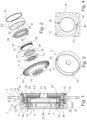
- Nachfolgend wird ein Ausführungsbeispiel der Erfindung anhand einer Zeichnung näher erläutert. Hierin zeigen:
- Fig. 1
- ein Wellgetriebe in Schnittdarstellung,
- Fig. 2
- das Wellgetriebe in Explosionsdarstellung,
- Fig. 3
- ein Abtriebselement des Wellgetriebes in perspektivischer Ansicht,
- Fig. 4
- ein Detail eines Antriebselements des Wellgetriebes.
- Ein insgesamt mit dem Bezugszeichen 1 gekennzeichnetes Wellgetriebe kommt als Stellgetriebe eines elektromechanischen Nockenwellenverstellers zum Einsatz. Das Wellgetriebe 1 dient der Verstellung einer Auslassnockenwelle eines Verbrennungsmotors. Hinsichtlich der prinzipiellen Funktion des Wellgetriebes 1 wird auf den eingangs zitierten Stand der Technik verwiesen.
- Das Wellgetriebe 1 weist ein Gehäuseelement 2 auf, welches einstückig mit einem Kettenrad 3 ausgebildet ist. Das Gehäuseelement 2 einschließlich des Kettenrades 3 wird kurz auch als Gehäuse des Wellgetriebes 1 bezeichnet. Das Gehäuse hat eine zylindrische Grundform, wobei sich die Innenumfangsfläche des Gehäuses zur Abtriebsseite des Wellgetriebes 1 hin gestuft aufweitet.
- In dem Kettenrad 3, welches als Getriebeelement eines Umschlingungsgetriebes, nämlich Kettengetriebes, in an sich bekannter Weise über die Kurbelwelle des Verbrennungsmotors angetrieben wird, ist ein Abtriebselement 4 gelagert. Das Abtriebselement 4 ist von der abtriebsseitigen Stirnseite des Wellgetriebes 1 aus in das Gehäuseelement 2 eingesetzt und mit Hilfe eines Sicherungsrings 18 in Axialrichtung gesichert. In der entgegengesetzten Axialrichtung läuft das Abtriebselement 4 an eine ringscheibenförmige Axiallagerfläche 23 an, welche unmittelbar durch das Gehäuseelement 2 gebildet ist und allgemein als ringscheibenförmige Fläche 23 bezeichnet wird.
- Durch das Gehäuseelement 2 ist ferner eine Radiallagerfläche 25 gebildet, in welche der mit 5 bezeichnete zylindrische Abschnitt des Abtriebselements 4 eingesetzt und damit in Radialrichtung gelagert ist. An den zylindrischen Abschnitt 5 schließt sich ein Boden 9 des Abtriebselements 4 an, welcher eine mittige Öffnung 22 aufweist. Im eingebauten Zustand des Wellgetriebes 1 ist durch die Öffnung 22 eine nicht dargestellte Zentralschraube durchgesteckt, mit welcher die abtriebsseitigen Komponenten des Wellgetriebes 1 an der zu verstellenden Nockenwelle befestigt sind.
- In dem vom Gehäuse umschlossenen Innenraum des Wellgetriebes 1 befindet sich ein Wellgenerator 6, welcher in an sich bekannter Weise ein als Kugellager ausgebildetes Wälzlager 7 umfasst. Ein Innenring 8 des Wälzlagers 7 wird - optional über eine nicht dargestellte Ausgleichskupplung - mittels eines nicht dargestellten Elektromotors angetrieben. Der Innenring 8 weist eine nicht kreisrunde, elliptische Außenumfangsfläche auf, auf welcher Kugeln 10 als Wälzkörper abrollen. Die Kugeln 10, welche in einem Käfig 11 geführt sind, kontaktieren einen Außenring 12, der im Gegensatz zum Innenring 8 nachgiebig ist.
- Der Außenring 12 des Wellgenerators 6 ist innerhalb eines nachgiebigen Getriebeelements 19 in Form eines Verzahnungstopfes angeordnet, welcher allgemein auch als elastisches Getriebeelement bezeichnet wird. Hierbei umgibt ein mit einer Außenverzahnung 13 versehener Bereich des nachgiebigen Getriebeelements 19 den Außenring 12. Die Außenverzahnung 13 ist Teil eines Hülsenabschnitts 24 des nachgiebigen Getriebeelements 19. Durch die nicht kreisrunde Form des Innenrings 8 wird die Außenverzahnung 13 an zwei einander diametral gegenüberliegenden Stellen in eine Innenverzahnung 14 gezwungen, welche durch das Gehäuseelement 2 gebildet ist. Die Anzahl der Zähne der Außenverzahnung 13 ist geringfügig, nämlich um zwei, geringer als die Anzahl der Zähne der Innenverzahnung 14. Dies führt dazu, dass eine volle Umdrehung des Innenrings 8 in Relation zum Gehäuseelement 2 in eine vergleichsweise geringe Verschwenkung zwischen dem Gehäuseelement 2 und dem Abtriebselement 4 umgesetzt wird. Bei einer Drehung des Innenrings 8 gegenüber dem Gehäuseelement 2, das heißt Antriebselement des Wellgetriebes 1, nach rechts wird das Abtriebselement 4 gegenüber dem Gehäuseelement 2 nach links verdreht und umgekehrt. Das Wellgetriebe 1 ist damit als Minusgetriebe konzipiert.
- Der mit 20 bezeichnete Boden des nachgiebigen Getriebeelementes 19 ist in seinem inneren Bereich fest mit dem vergleichsweise massiven, eine wesentlich größere Wandstärke aufweisenden Boden 9 des Abtriebselementes 4 verbunden. Ebenso ist mit dem Boden 9 des Abtriebselementes 4 ein Sicherungstopf 27 verbunden, bei welchem es sich, ebenso wie bei dem nachgiebigen Getriebeelement 19, um ein dünnwandiges Blechteil handelt. Der Sicherungstopf 27 weist einen Scheibenabschnitt 28 auf, welcher dem Boden 20 des nachgiebigen Getriebeelements 19 unmittelbar vorgesetzt ist und zusammen mit diesem mit Hilfe der bereits erwähnten Zentralschraube an der Nockenwelle befestigt ist. Der Scheibenabschnitt 28 geht an seinem inneren Rand in einen Zapfen 21 über, welcher die Öffnung 22 begrenzt.
- Der radial äußere Rand des Scheibenabschnitts 28 geht in einen Hülsenabschnitt 29 des Sicherungstopfes 27 über, welcher radial innerhalb des Hülsenabschnitts 24 des nachgiebigen Getriebeelements 19 angeordnet und konzentrisch zu diesem ausgerichtet ist. An den dem Scheibenabschnitt 28 abgewandten Rand des Hülsenabschnitts 29 wiederum schließt ein radial nach außen gerichteter Flansch 30 des Sicherungstopfes 27 an, welcher einen Axialanschlag gegenüber dem Außenring 12 und damit gegenüber dem gesamten Wellgenerator 6 darstellt.
- Ein Axialanschlag gegenüber dem Wellgenerator 6 in der entgegengesetzten Richtung, das heißt zur Frontseite des Wellgetriebes 1 hin, ist durch einen Innenbord 26 gebildet, welcher Bestandteil des Gehäuseelementes 2 ist. Aufgrund des Innenbordes 26 kann der Wellgenerator 6 ebenso wie das nachgiebige Getriebeelement 19 ausschließlich von der abtriebsseitigen Stirnseite des Wellgetriebes 1 aus in das Gehäuseelement 2 eingesetzt werden. An den Innenbord 26 schließt der mit der Innenverzahnung 14 versehene, hohlzylindrische Abschnitt des Gehäuseelementes 2 an. An diesen Abschnitt wiederum schließt die ringscheibenförmige Fläche 23 an, welche unter anderem als Axiallagerfläche gegenüber dem Abtriebselement 4 fungiert.
- Die Innenverzahnung 14 befindet sich ebenso wie ein an die Axiallagerfläche 23 anschließender, vergleichsweise dünnwandiger Abschnitt des Gehäuseelementes 2 in einem insgesamt mit 15 bezeichneten zylindrischen Abschnitt des Gehäuses 2. Aus dem zylindrischen Abschnitt 15 ragt radial nach außen ein mit 16 bezeichneter Scheibenabschnitt heraus, welcher als Kettenrad 3 ausgebildet ist und zahlreiche Öffnungen 17 aufweist, die der Einsparung von Gewicht und Massenträgheitsmoment des drehbaren Gehäuseelementes 2 dienen.
- Am zylindrischen Abschnitt 5 des Abtriebselements 4 sind Umfangsanschläge 31, 32 erkennbar, welche einer Verdrehwinkelbegrenzung 33 zuzurechnen sind. Die Verdrehwinkelbegrenzung 33 umfasst ferner einen Anschlagblock 40, welcher durch das Gehäuseelement 2 gebildet ist und Anschlagflächen 41, 42 aufweist, die mit den Umfangsanschlägen 31, 32 zusammenwirken. Durch die Verdrehwinkelbegrenzung 33 ist der Schwenkbereich des Abtriebselements 4 gegenüber dem Gehäuseelement 2 und damit der Verstellbereich des Wellgetriebes 1 begrenzt.
- Das Abtriebselement 4 ist gegenüber dem Gehäuseelement 2 durch ein Federelement 35, nämlich eine Torsionsfeder, vorgespannt. Das Federelement 35 weist eine Mehrzahl, im Ausführungsbeispiel vier, an Windungen 39 auf, welche in einem Ringraum radial außerhalb des Hülsenabschnitts 24 sowie radial innerhalb des zylindrischen Abschnitts 5 des Abtriebselementes 4 angeordnet sind. Stirnseitig ist der Ringraum, in welchem sich die Windungen 39 befinden, einerseits durch die ringscheibenförmige Fläche 23 und andererseits durch den Boden 9 des Abtriebselementes 4 begrenzt. Die mit 36 und 37 bezeichneten Federenden des Federelementes 35 sind in Axialrichtung des Wellgetriebes 1 ausgerichtet und greifen in eine Bohrung 38 im Gehäuseelement 2 beziehungsweise in eine Bohrung 34 am Rand des Bodens 9 des Abtriebselementes 4 ein. Bei der Montage des Wellgetriebes 1 wird das Federelement 35 zusammen mit dem Abtriebselement 4 in das Gehäuseelement 2 eingesetzt.
-
- 1
- Wellgetriebe
- 2
- Gehäuseelement
- 3
- Kettenrad
- 4
- Abtriebselement
- 5
- zylindrischer Abschnitt
- 6
- Wellgenerator
- 7
- Wälzlager
- 8
- Innenring
- 9
- Boden
- 10
- Kugel
- 11
- Käfig
- 12
- Außenring
- 13
- Außenverzahnung
- 14
- Innenverzahnung
- 15
- zylindrischer Abschnitt
- 16
- Scheibenabschnitt
- 17
- Bohrung
- 18
- Sicherungsring
- 19
- nachgiebiges Getriebeelement
- 20
- Boden
- 21
- Zapfen
- 22
- Öffnung
- 23
- Axiallagerfläche, ringscheibenförmige Fläche
- 24
- Hülsenabschnitt
- 25
- Radiallagerfläche
- 26
- Innenbord
- 27
- Sicherungstopf
- 28
- Scheibenabschnitt
- 29
- Hülsenabschnitt
- 30
- Flansch
- 31
- Umfangsanschlag
- 32
- Umfangsanschlag
- 33
- Verdrehwinkelbegrenzung
- 34
- Bohrung
- 35
- Federelement, Torsionsfeder
- 36
- Federende
- 37
- Federende
- 38
- Bohrung
- 39
- Windung
- 40
- Anschlagblock
- 41
- Anschlagfläche
- 42
- Anschlagfläche
Claims (10)
- Wellgetriebe (1), mit einem innenverzahnten Gehäuseelement (2), einem topfförmigen, im Gehäuseelement (2) gelagerten Abtriebselement (4), sowie einem ebenfalls topfförmigen, mit dem Abtriebselement (4) verbundenen, nachgiebigen Getriebeelement (19), welches eine mit einer Innenverzahnung (14) des Gehäuseelementes (2) kämmende Außenverzahnung (13) aufweist, gekennzeichnet durch ein zwischen dem Gehäuseelement (2) und dem Abtriebselement (4) wirksamen Federelement (35), welches in einem Ringraum angeordnet ist, der radial nach innen durch einen Hülsenabschnitt (24) des nachgiebigen Getriebeelementes (19), radial nach außen durch einen zylindrischen Abschnitt (5) des Abtriebselementes (4), und in Axialrichtung einerseits durch eine ringscheibenförmige Fläche (23) des Gehäuseelementes (2) und andererseits durch einen Boden (9) des Abtriebselementes (4) begrenzt ist.
- Wellgetriebe (1) nach Anspruch 1, dadurch gekennzeichnet, dass das Federelement (35) als Torsionsfeder ausgebildet ist.
- Wellgetriebe (1) nach Anspruch 2, dadurch gekennzeichnet, dass die Torsionsfeder (35) eine Mehrzahl an Windungen (39) aufweist.
- Wellgetriebe (1) nach Anspruch 3, dadurch gekennzeichnet, dass die Torsionsfeder (35) in Axialrichtung des Gehäuseelementes (2) sowie des Abtriebselementes (4) ausgerichtete Federenden (36,37) aufweist, welche in Bohrungen (38,34) des Gehäuseelementes (2) beziehungsweise des Abtriebselementes (4) gehalten sind.
- Wellgetriebe (1) nach einem der Ansprüche 1 bis 4, dadurch gekennzeichnet, dass das Abtriebselement (4) Konturen (31,32) einer Verdrehwinkelbegrenzung (33) aufweist.
- Wellgetriebe (1) nach einem der Ansprüche 1 bis 5, gekennzeichnet durch einen in das nachgiebige Getriebeelement (19) eingesetzten Sicherungstopf (27), welcher als Axialsicherungselement gegenüber einem zur Verformung des nachgiebigen Getriebeelementes (19) vorgesehenen Wellgenerator (6) fungiert.
- Wellgetriebe (1) nach einem der Ansprüche 1 bis 6, dadurch gekennzeichnet, dass die ringscheibenförmige Fläche (23) des Gehäuseelementes (2) als Axiallagerfläche gegenüber dem Abtriebselement (4) vorgesehen ist.
- Wellgetriebe (1) nach einem der Ansprüche 1 bis 7, dadurch gekennzeichnet, dass das Gehäuseelement (2) einstückig mit einem Kettenrad (3) ausgebildet ist.
- Wellgetriebe (1) nach einem der Ansprüche 1 bis 8, dadurch gekennzeichnet, dass dieses als Minusgetriebe ausgebildet ist.
- Verwendung eines Wellgetriebes (1) nach Anspruch 9 in einem elektromechanischen Nockenwellenversteller.
Applications Claiming Priority (2)
| Application Number | Priority Date | Filing Date | Title |
|---|---|---|---|
| DE102018128028.9A DE102018128028B3 (de) | 2018-11-09 | 2018-11-09 | Wellgetriebe für einen elektromechanischen Nockenwellenversteller |
| PCT/DE2019/100827 WO2020094174A1 (de) | 2018-11-09 | 2019-09-20 | Wellgetriebe für einen elektromechanischen nockenwellenversteller |
Publications (2)
| Publication Number | Publication Date |
|---|---|
| EP3877672A1 EP3877672A1 (de) | 2021-09-15 |
| EP3877672B1 true EP3877672B1 (de) | 2023-11-08 |
Family
ID=68280649
Family Applications (1)
| Application Number | Title | Priority Date | Filing Date |
|---|---|---|---|
| EP19789580.8A Active EP3877672B1 (de) | 2018-11-09 | 2019-09-20 | Wellgetriebe für einen elektromechanischen nockenwellenversteller |
Country Status (7)
| Country | Link |
|---|---|
| US (1) | US11891927B2 (de) |
| EP (1) | EP3877672B1 (de) |
| JP (1) | JP7086287B2 (de) |
| KR (1) | KR102797361B1 (de) |
| CN (1) | CN112969867B (de) |
| DE (1) | DE102018128028B3 (de) |
| WO (1) | WO2020094174A1 (de) |
Families Citing this family (2)
| Publication number | Priority date | Publication date | Assignee | Title |
|---|---|---|---|---|
| DE102019120100A1 (de) * | 2019-07-25 | 2020-10-08 | Schaeffler Technologies AG & Co. KG | Wellgetriebe und Verfahren zur Montage eines Wellgetriebes |
| DE102024115662B3 (de) * | 2024-06-25 | 2026-01-08 | Schaeffler Technologies AG & Co. KG | Nockenwellenversteller |
Family Cites Families (24)
| Publication number | Priority date | Publication date | Assignee | Title |
|---|---|---|---|---|
| JPS6113050A (ja) * | 1984-06-27 | 1986-01-21 | Hitachi Ltd | 関節機構 |
| BR9304028A (pt) | 1993-10-18 | 1995-06-06 | Freios Varga Sa | Dispositivo descarregador para compressor governado de sistema de freios a ar para veículos automotores |
| EP1364140A1 (de) * | 2001-02-08 | 2003-11-26 | Oechsler Aktiengesellschaft | Wellgetriebe mit haubenförmigem abtriebsring |
| DE10352461B4 (de) | 2003-11-07 | 2012-12-06 | Murrplastik Systemtechnik Gmbh | Vorrichtung zur Führung mindestens einer Leitung |
| DE10352361B4 (de) * | 2003-11-10 | 2020-08-27 | Schaeffler Technologies AG & Co. KG | Nockenwellenversteller mit elektrischem Antrieb |
| DE102004009128A1 (de) * | 2004-02-25 | 2005-09-15 | Ina-Schaeffler Kg | Elektrischer Nockenwellenversteller |
| DE102005048570A1 (de) * | 2005-10-10 | 2007-04-12 | Ortloff-Technologie Gmbh | Motorgetriebe mit Torquemotor und Spannungswellgetriebe |
| JP4847427B2 (ja) * | 2007-10-17 | 2011-12-28 | 株式会社日本自動車部品総合研究所 | 電動ブレーキ装置 |
| US8584633B2 (en) * | 2009-08-06 | 2013-11-19 | Delphi Technologies, Inc. | Harmonic drive camshaft phaser with bias spring |
| DE102010006392B3 (de) * | 2010-02-01 | 2011-05-12 | Ovalo Gmbh | Spannungswellengetriebe und Nockenwellenversteller mit Spannungswellengetriebe |
| EP2625441B1 (de) * | 2010-10-07 | 2019-09-11 | TQ-Systems GmbH | Getriebe, motorgetriebeeinheit, fahrzeug, generator mit einem getriebe und kraftübertragungselement |
| JP5206807B2 (ja) * | 2011-01-26 | 2013-06-12 | 株式会社デンソー | バルブタイミング調整装置 |
| DE102011004070A1 (de) * | 2011-02-14 | 2012-08-16 | Schaeffler Technologies Gmbh & Co. Kg | 3-Wellen-Verstellgetriebe mit zwei mechanischen Anschlägen |
| US8677961B2 (en) * | 2011-07-18 | 2014-03-25 | Delphi Technologies, Inc. | Harmonic drive camshaft phaser with lock pin for selectivley preventing a change in phase relationship |
| US20150033906A1 (en) * | 2013-08-01 | 2015-02-05 | Delphi Technologies, Inc. | Axially compact electrically driven camshaft phaser |
| DE102013216183A1 (de) * | 2013-08-14 | 2015-02-19 | Schaeffler Technologies Gmbh & Co. Kg | Verstelleinrichtung |
| DE102014003219A1 (de) * | 2014-03-05 | 2015-09-10 | Audi Ag | Elektromechanischer Rotationsdämpfer mit Zug- und Druckanschlag |
| US9151191B1 (en) | 2014-04-01 | 2015-10-06 | Delphi Technologies, Inc. | Electrically actuated camshaft phaser |
| DE102015210707B3 (de) * | 2015-06-11 | 2016-12-01 | Schaeffler Technologies AG & Co. KG | Drei-Wellengetriebe |
| US9957852B2 (en) * | 2016-06-14 | 2018-05-01 | Delphi Technologies Ip Limited | Cushion ring assembly for a sprocket driven by a chain |
| DE102017119860A1 (de) * | 2016-09-30 | 2018-04-05 | Schaeffler Technologies AG & Co. KG | Wellgetriebe |
| DE102016220454A1 (de) * | 2016-10-19 | 2018-04-19 | Schaeffler Technologies AG & Co. KG | Wellgetriebeanordnung für ein Fahrzeug sowie Fahrzeug mit dem Wellgetriebe |
| DE102017109303B3 (de) * | 2017-05-02 | 2018-06-21 | Schaeffler Technologies AG & Co. KG | Aktor zur Verstellung des Verdichtungsverhältnisses eines Hubkolbenmotors |
| DE102017121320B3 (de) * | 2017-09-14 | 2018-10-11 | Schaeffler Technologies AG & Co. KG | Wellgetriebe |
-
2018
- 2018-11-09 DE DE102018128028.9A patent/DE102018128028B3/de not_active Expired - Fee Related
-
2019
- 2019-09-20 KR KR1020217012138A patent/KR102797361B1/ko active Active
- 2019-09-20 JP JP2021524978A patent/JP7086287B2/ja active Active
- 2019-09-20 WO PCT/DE2019/100827 patent/WO2020094174A1/de not_active Ceased
- 2019-09-20 CN CN201980073788.XA patent/CN112969867B/zh active Active
- 2019-09-20 US US17/292,527 patent/US11891927B2/en active Active
- 2019-09-20 EP EP19789580.8A patent/EP3877672B1/de active Active
Also Published As
| Publication number | Publication date |
|---|---|
| US20210396162A1 (en) | 2021-12-23 |
| KR102797361B1 (ko) | 2025-04-21 |
| JP2022506874A (ja) | 2022-01-17 |
| WO2020094174A1 (de) | 2020-05-14 |
| KR20210089649A (ko) | 2021-07-16 |
| CN112969867A (zh) | 2021-06-15 |
| CN112969867B (zh) | 2024-10-22 |
| US11891927B2 (en) | 2024-02-06 |
| EP3877672A1 (de) | 2021-09-15 |
| JP7086287B2 (ja) | 2022-06-17 |
| DE102018128028B3 (de) | 2020-03-05 |
Similar Documents
| Publication | Publication Date | Title |
|---|---|---|
| DE102016217051A1 (de) | Nockenwellenversteller | |
| DE102016219076A1 (de) | Wellgetriebe | |
| DE102017126527A1 (de) | Wellgetriebe | |
| WO2017194045A1 (de) | Wellgetriebe | |
| DE102019102264B4 (de) | Wellgetriebe und Verfahren zur Montage eines Nockenwellenverstellers | |
| WO2017206988A1 (de) | Stellgetriebe | |
| WO2018215009A1 (de) | Nockenwellenversteller | |
| DE102019105760A1 (de) | Wellgetriebe und Verfahren zur Herstellung eines elastischen Getriebebauteils | |
| DE102016223796A1 (de) | Wellgetriebe | |
| DE102017119860A1 (de) | Wellgetriebe | |
| WO2020020403A1 (de) | Wellgetriebe | |
| WO2018095463A1 (de) | Flexibles getriebebauteil | |
| DE102018102774B3 (de) | Wellgetriebe und Verfahren zur Montage eines Wellgetriebes | |
| DE102016210700A1 (de) | Flexibles Getriebeelement | |
| DE102018128028B3 (de) | Wellgetriebe für einen elektromechanischen Nockenwellenversteller | |
| DE102016201590A1 (de) | Wellgetriebe | |
| WO2018215008A1 (de) | Nockenwellenversteller | |
| DE102019132995A1 (de) | Wellgetriebe und Verfahren zur Herstellung eines Innenrings eines Wellgenerators | |
| WO2020083426A1 (de) | Wellgetriebe und verfahren zur montage eines wellgetriebes | |
| WO2019185088A1 (de) | Wellgetriebe | |
| DE102016207927B4 (de) | Stellantrieb | |
| DE102016210703A1 (de) | Wellgetriebe | |
| DE102020129738B4 (de) | Wellgetriebe, Verfahren zur Herstellung eines Wellgetriebes und Brennkraftmaschine mit Wellgetriebe aufweisenden Nockenwellenverstellern | |
| EP3578769B1 (de) | Verstellvorrichtung, insbesondere nockenwellenversteller | |
| WO2018219377A1 (de) | Dreiwellengetriebe |
Legal Events
| Date | Code | Title | Description |
|---|---|---|---|
| STAA | Information on the status of an ep patent application or granted ep patent |
Free format text: STATUS: UNKNOWN |
|
| STAA | Information on the status of an ep patent application or granted ep patent |
Free format text: STATUS: THE INTERNATIONAL PUBLICATION HAS BEEN MADE |
|
| PUAI | Public reference made under article 153(3) epc to a published international application that has entered the european phase |
Free format text: ORIGINAL CODE: 0009012 |
|
| STAA | Information on the status of an ep patent application or granted ep patent |
Free format text: STATUS: REQUEST FOR EXAMINATION WAS MADE |
|
| 17P | Request for examination filed |
Effective date: 20210609 |
|
| AK | Designated contracting states |
Kind code of ref document: A1 Designated state(s): AL AT BE BG CH CY CZ DE DK EE ES FI FR GB GR HR HU IE IS IT LI LT LU LV MC MK MT NL NO PL PT RO RS SE SI SK SM TR |
|
| DAV | Request for validation of the european patent (deleted) | ||
| DAX | Request for extension of the european patent (deleted) | ||
| GRAP | Despatch of communication of intention to grant a patent |
Free format text: ORIGINAL CODE: EPIDOSNIGR1 |
|
| STAA | Information on the status of an ep patent application or granted ep patent |
Free format text: STATUS: GRANT OF PATENT IS INTENDED |
|
| P01 | Opt-out of the competence of the unified patent court (upc) registered |
Effective date: 20230522 |
|
| INTG | Intention to grant announced |
Effective date: 20230623 |
|
| GRAS | Grant fee paid |
Free format text: ORIGINAL CODE: EPIDOSNIGR3 |
|
| GRAA | (expected) grant |
Free format text: ORIGINAL CODE: 0009210 |
|
| STAA | Information on the status of an ep patent application or granted ep patent |
Free format text: STATUS: THE PATENT HAS BEEN GRANTED |
|
| AK | Designated contracting states |
Kind code of ref document: B1 Designated state(s): AL AT BE BG CH CY CZ DE DK EE ES FI FR GB GR HR HU IE IS IT LI LT LU LV MC MK MT NL NO PL PT RO RS SE SI SK SM TR |
|
| REG | Reference to a national code |
Ref country code: GB Ref legal event code: FG4D Free format text: NOT ENGLISH |
|
| REG | Reference to a national code |
Ref country code: CH Ref legal event code: EP |
|
| REG | Reference to a national code |
Ref country code: DE Ref legal event code: R096 Ref document number: 502019009890 Country of ref document: DE |
|
| REG | Reference to a national code |
Ref country code: IE Ref legal event code: FG4D Free format text: LANGUAGE OF EP DOCUMENT: GERMAN |
|
| REG | Reference to a national code |
Ref country code: LT Ref legal event code: MG9D |
|
| REG | Reference to a national code |
Ref country code: NL Ref legal event code: MP Effective date: 20231108 |
|
| PG25 | Lapsed in a contracting state [announced via postgrant information from national office to epo] |
Ref country code: GR Free format text: LAPSE BECAUSE OF FAILURE TO SUBMIT A TRANSLATION OF THE DESCRIPTION OR TO PAY THE FEE WITHIN THE PRESCRIBED TIME-LIMIT Effective date: 20240209 |
|
| PG25 | Lapsed in a contracting state [announced via postgrant information from national office to epo] |
Ref country code: IS Free format text: LAPSE BECAUSE OF FAILURE TO SUBMIT A TRANSLATION OF THE DESCRIPTION OR TO PAY THE FEE WITHIN THE PRESCRIBED TIME-LIMIT Effective date: 20240308 |
|
| PG25 | Lapsed in a contracting state [announced via postgrant information from national office to epo] |
Ref country code: LT Free format text: LAPSE BECAUSE OF FAILURE TO SUBMIT A TRANSLATION OF THE DESCRIPTION OR TO PAY THE FEE WITHIN THE PRESCRIBED TIME-LIMIT Effective date: 20231108 |
|
| PG25 | Lapsed in a contracting state [announced via postgrant information from national office to epo] |
Ref country code: NL Free format text: LAPSE BECAUSE OF FAILURE TO SUBMIT A TRANSLATION OF THE DESCRIPTION OR TO PAY THE FEE WITHIN THE PRESCRIBED TIME-LIMIT Effective date: 20231108 |
|
| PG25 | Lapsed in a contracting state [announced via postgrant information from national office to epo] |
Ref country code: ES Free format text: LAPSE BECAUSE OF FAILURE TO SUBMIT A TRANSLATION OF THE DESCRIPTION OR TO PAY THE FEE WITHIN THE PRESCRIBED TIME-LIMIT Effective date: 20231108 |
|
| PG25 | Lapsed in a contracting state [announced via postgrant information from national office to epo] |
Ref country code: NL Free format text: LAPSE BECAUSE OF FAILURE TO SUBMIT A TRANSLATION OF THE DESCRIPTION OR TO PAY THE FEE WITHIN THE PRESCRIBED TIME-LIMIT Effective date: 20231108 Ref country code: LT Free format text: LAPSE BECAUSE OF FAILURE TO SUBMIT A TRANSLATION OF THE DESCRIPTION OR TO PAY THE FEE WITHIN THE PRESCRIBED TIME-LIMIT Effective date: 20231108 Ref country code: IS Free format text: LAPSE BECAUSE OF FAILURE TO SUBMIT A TRANSLATION OF THE DESCRIPTION OR TO PAY THE FEE WITHIN THE PRESCRIBED TIME-LIMIT Effective date: 20240308 Ref country code: GR Free format text: LAPSE BECAUSE OF FAILURE TO SUBMIT A TRANSLATION OF THE DESCRIPTION OR TO PAY THE FEE WITHIN THE PRESCRIBED TIME-LIMIT Effective date: 20240209 Ref country code: ES Free format text: LAPSE BECAUSE OF FAILURE TO SUBMIT A TRANSLATION OF THE DESCRIPTION OR TO PAY THE FEE WITHIN THE PRESCRIBED TIME-LIMIT Effective date: 20231108 Ref country code: BG Free format text: LAPSE BECAUSE OF FAILURE TO SUBMIT A TRANSLATION OF THE DESCRIPTION OR TO PAY THE FEE WITHIN THE PRESCRIBED TIME-LIMIT Effective date: 20240208 Ref country code: PT Free format text: LAPSE BECAUSE OF FAILURE TO SUBMIT A TRANSLATION OF THE DESCRIPTION OR TO PAY THE FEE WITHIN THE PRESCRIBED TIME-LIMIT Effective date: 20240308 |
|
| PG25 | Lapsed in a contracting state [announced via postgrant information from national office to epo] |
Ref country code: SE Free format text: LAPSE BECAUSE OF FAILURE TO SUBMIT A TRANSLATION OF THE DESCRIPTION OR TO PAY THE FEE WITHIN THE PRESCRIBED TIME-LIMIT Effective date: 20231108 Ref country code: RS Free format text: LAPSE BECAUSE OF FAILURE TO SUBMIT A TRANSLATION OF THE DESCRIPTION OR TO PAY THE FEE WITHIN THE PRESCRIBED TIME-LIMIT Effective date: 20231108 Ref country code: PL Free format text: LAPSE BECAUSE OF FAILURE TO SUBMIT A TRANSLATION OF THE DESCRIPTION OR TO PAY THE FEE WITHIN THE PRESCRIBED TIME-LIMIT Effective date: 20231108 Ref country code: NO Free format text: LAPSE BECAUSE OF FAILURE TO SUBMIT A TRANSLATION OF THE DESCRIPTION OR TO PAY THE FEE WITHIN THE PRESCRIBED TIME-LIMIT Effective date: 20240208 Ref country code: LV Free format text: LAPSE BECAUSE OF FAILURE TO SUBMIT A TRANSLATION OF THE DESCRIPTION OR TO PAY THE FEE WITHIN THE PRESCRIBED TIME-LIMIT Effective date: 20231108 Ref country code: HR Free format text: LAPSE BECAUSE OF FAILURE TO SUBMIT A TRANSLATION OF THE DESCRIPTION OR TO PAY THE FEE WITHIN THE PRESCRIBED TIME-LIMIT Effective date: 20231108 |
|
| PG25 | Lapsed in a contracting state [announced via postgrant information from national office to epo] |
Ref country code: DK Free format text: LAPSE BECAUSE OF FAILURE TO SUBMIT A TRANSLATION OF THE DESCRIPTION OR TO PAY THE FEE WITHIN THE PRESCRIBED TIME-LIMIT Effective date: 20231108 |
|
| PG25 | Lapsed in a contracting state [announced via postgrant information from national office to epo] |
Ref country code: CZ Free format text: LAPSE BECAUSE OF FAILURE TO SUBMIT A TRANSLATION OF THE DESCRIPTION OR TO PAY THE FEE WITHIN THE PRESCRIBED TIME-LIMIT Effective date: 20231108 |
|
| PG25 | Lapsed in a contracting state [announced via postgrant information from national office to epo] |
Ref country code: SK Free format text: LAPSE BECAUSE OF FAILURE TO SUBMIT A TRANSLATION OF THE DESCRIPTION OR TO PAY THE FEE WITHIN THE PRESCRIBED TIME-LIMIT Effective date: 20231108 |
|
| PG25 | Lapsed in a contracting state [announced via postgrant information from national office to epo] |
Ref country code: SM Free format text: LAPSE BECAUSE OF FAILURE TO SUBMIT A TRANSLATION OF THE DESCRIPTION OR TO PAY THE FEE WITHIN THE PRESCRIBED TIME-LIMIT Effective date: 20231108 Ref country code: SK Free format text: LAPSE BECAUSE OF FAILURE TO SUBMIT A TRANSLATION OF THE DESCRIPTION OR TO PAY THE FEE WITHIN THE PRESCRIBED TIME-LIMIT Effective date: 20231108 Ref country code: RO Free format text: LAPSE BECAUSE OF FAILURE TO SUBMIT A TRANSLATION OF THE DESCRIPTION OR TO PAY THE FEE WITHIN THE PRESCRIBED TIME-LIMIT Effective date: 20231108 Ref country code: IT Free format text: LAPSE BECAUSE OF FAILURE TO SUBMIT A TRANSLATION OF THE DESCRIPTION OR TO PAY THE FEE WITHIN THE PRESCRIBED TIME-LIMIT Effective date: 20231108 Ref country code: EE Free format text: LAPSE BECAUSE OF FAILURE TO SUBMIT A TRANSLATION OF THE DESCRIPTION OR TO PAY THE FEE WITHIN THE PRESCRIBED TIME-LIMIT Effective date: 20231108 Ref country code: DK Free format text: LAPSE BECAUSE OF FAILURE TO SUBMIT A TRANSLATION OF THE DESCRIPTION OR TO PAY THE FEE WITHIN THE PRESCRIBED TIME-LIMIT Effective date: 20231108 Ref country code: CZ Free format text: LAPSE BECAUSE OF FAILURE TO SUBMIT A TRANSLATION OF THE DESCRIPTION OR TO PAY THE FEE WITHIN THE PRESCRIBED TIME-LIMIT Effective date: 20231108 |
|
| REG | Reference to a national code |
Ref country code: DE Ref legal event code: R097 Ref document number: 502019009890 Country of ref document: DE |
|
| PLBE | No opposition filed within time limit |
Free format text: ORIGINAL CODE: 0009261 |
|
| STAA | Information on the status of an ep patent application or granted ep patent |
Free format text: STATUS: NO OPPOSITION FILED WITHIN TIME LIMIT |
|
| 26N | No opposition filed |
Effective date: 20240809 |
|
| PG25 | Lapsed in a contracting state [announced via postgrant information from national office to epo] |
Ref country code: SI Free format text: LAPSE BECAUSE OF FAILURE TO SUBMIT A TRANSLATION OF THE DESCRIPTION OR TO PAY THE FEE WITHIN THE PRESCRIBED TIME-LIMIT Effective date: 20231108 |
|
| PG25 | Lapsed in a contracting state [announced via postgrant information from national office to epo] |
Ref country code: SI Free format text: LAPSE BECAUSE OF FAILURE TO SUBMIT A TRANSLATION OF THE DESCRIPTION OR TO PAY THE FEE WITHIN THE PRESCRIBED TIME-LIMIT Effective date: 20231108 |
|
| PG25 | Lapsed in a contracting state [announced via postgrant information from national office to epo] |
Ref country code: MC Free format text: LAPSE BECAUSE OF FAILURE TO SUBMIT A TRANSLATION OF THE DESCRIPTION OR TO PAY THE FEE WITHIN THE PRESCRIBED TIME-LIMIT Effective date: 20231108 |
|
| REG | Reference to a national code |
Ref country code: CH Ref legal event code: PL |
|
| PG25 | Lapsed in a contracting state [announced via postgrant information from national office to epo] |
Ref country code: LU Free format text: LAPSE BECAUSE OF NON-PAYMENT OF DUE FEES Effective date: 20240920 |
|
| GBPC | Gb: european patent ceased through non-payment of renewal fee |
Effective date: 20240920 |
|
| PG25 | Lapsed in a contracting state [announced via postgrant information from national office to epo] |
Ref country code: GB Free format text: LAPSE BECAUSE OF NON-PAYMENT OF DUE FEES Effective date: 20240920 |
|
| REG | Reference to a national code |
Ref country code: BE Ref legal event code: MM Effective date: 20240930 |
|
| PG25 | Lapsed in a contracting state [announced via postgrant information from national office to epo] |
Ref country code: BE Free format text: LAPSE BECAUSE OF NON-PAYMENT OF DUE FEES Effective date: 20240930 |
|
| PG25 | Lapsed in a contracting state [announced via postgrant information from national office to epo] |
Ref country code: FR Free format text: LAPSE BECAUSE OF NON-PAYMENT OF DUE FEES Effective date: 20240930 |
|
| PG25 | Lapsed in a contracting state [announced via postgrant information from national office to epo] |
Ref country code: CH Free format text: LAPSE BECAUSE OF NON-PAYMENT OF DUE FEES Effective date: 20240930 |
|
| PG25 | Lapsed in a contracting state [announced via postgrant information from national office to epo] |
Ref country code: IE Free format text: LAPSE BECAUSE OF NON-PAYMENT OF DUE FEES Effective date: 20240920 |
|
| PG25 | Lapsed in a contracting state [announced via postgrant information from national office to epo] |
Ref country code: FI Free format text: LAPSE BECAUSE OF FAILURE TO SUBMIT A TRANSLATION OF THE DESCRIPTION OR TO PAY THE FEE WITHIN THE PRESCRIBED TIME-LIMIT Effective date: 20231108 |
|
| REG | Reference to a national code |
Ref country code: AT Ref legal event code: MM01 Ref document number: 1629869 Country of ref document: AT Kind code of ref document: T Effective date: 20240920 |
|
| PGFP | Annual fee paid to national office [announced via postgrant information from national office to epo] |
Ref country code: DE Payment date: 20251119 Year of fee payment: 7 |
|
| PG25 | Lapsed in a contracting state [announced via postgrant information from national office to epo] |
Ref country code: AT Free format text: LAPSE BECAUSE OF NON-PAYMENT OF DUE FEES Effective date: 20240920 |
|
| PG25 | Lapsed in a contracting state [announced via postgrant information from national office to epo] |
Ref country code: CY Free format text: LAPSE BECAUSE OF FAILURE TO SUBMIT A TRANSLATION OF THE DESCRIPTION OR TO PAY THE FEE WITHIN THE PRESCRIBED TIME-LIMIT; INVALID AB INITIO Effective date: 20190920 |
|
| PG25 | Lapsed in a contracting state [announced via postgrant information from national office to epo] |
Ref country code: HU Free format text: LAPSE BECAUSE OF FAILURE TO SUBMIT A TRANSLATION OF THE DESCRIPTION OR TO PAY THE FEE WITHIN THE PRESCRIBED TIME-LIMIT; INVALID AB INITIO Effective date: 20190920 |
|
| PG25 | Lapsed in a contracting state [announced via postgrant information from national office to epo] |
Ref country code: TR Free format text: LAPSE BECAUSE OF FAILURE TO SUBMIT A TRANSLATION OF THE DESCRIPTION OR TO PAY THE FEE WITHIN THE PRESCRIBED TIME-LIMIT Effective date: 20231108 |