EP3877792B1 - Beleuchtungsoptik für reinigungsroboter - Google Patents
Beleuchtungsoptik für reinigungsroboter Download PDFInfo
- Publication number
- EP3877792B1 EP3877792B1 EP19883158.8A EP19883158A EP3877792B1 EP 3877792 B1 EP3877792 B1 EP 3877792B1 EP 19883158 A EP19883158 A EP 19883158A EP 3877792 B1 EP3877792 B1 EP 3877792B1
- Authority
- EP
- European Patent Office
- Prior art keywords
- light
- illuminator
- optic
- robotic cleaner
- cavity
- Prior art date
- Legal status (The legal status is an assumption and is not a legal conclusion. Google has not performed a legal analysis and makes no representation as to the accuracy of the status listed.)
- Active
Links
Images



Classifications
-
- A—HUMAN NECESSITIES
- A47—FURNITURE; DOMESTIC ARTICLES OR APPLIANCES; COFFEE MILLS; SPICE MILLS; SUCTION CLEANERS IN GENERAL
- A47L—DOMESTIC WASHING OR CLEANING; SUCTION CLEANERS IN GENERAL
- A47L9/00—Details or accessories of suction cleaners, e.g. mechanical means for controlling the suction or for effecting pulsating action; Storing devices specially adapted to suction cleaners or parts thereof; Carrying-vehicles specially adapted for suction cleaners
- A47L9/28—Installation of the electric equipment, e.g. adaptation or attachment to the suction cleaner; Controlling suction cleaners by electric means
- A47L9/30—Arrangement of illuminating devices
-
- G—PHYSICS
- G02—OPTICS
- G02B—OPTICAL ELEMENTS, SYSTEMS OR APPARATUS
- G02B6/00—Light guides; Structural details of arrangements comprising light guides and other optical elements, e.g. couplings
- G02B6/0001—Light guides; Structural details of arrangements comprising light guides and other optical elements, e.g. couplings specially adapted for lighting devices or systems
-
- G—PHYSICS
- G02—OPTICS
- G02B—OPTICAL ELEMENTS, SYSTEMS OR APPARATUS
- G02B6/00—Light guides; Structural details of arrangements comprising light guides and other optical elements, e.g. couplings
- G02B6/0001—Light guides; Structural details of arrangements comprising light guides and other optical elements, e.g. couplings specially adapted for lighting devices or systems
- G02B6/0011—Light guides; Structural details of arrangements comprising light guides and other optical elements, e.g. couplings specially adapted for lighting devices or systems the light guides being planar or of plate-like form
- G02B6/0013—Means for improving the coupling-in of light from the light source into the light guide
- G02B6/0023—Means for improving the coupling-in of light from the light source into the light guide provided by one optical element, or plurality thereof, placed between the light guide and the light source, or around the light source
- G02B6/0031—Reflecting element, sheet or layer
-
- G—PHYSICS
- G02—OPTICS
- G02B—OPTICAL ELEMENTS, SYSTEMS OR APPARATUS
- G02B6/00—Light guides; Structural details of arrangements comprising light guides and other optical elements, e.g. couplings
- G02B6/0001—Light guides; Structural details of arrangements comprising light guides and other optical elements, e.g. couplings specially adapted for lighting devices or systems
- G02B6/0011—Light guides; Structural details of arrangements comprising light guides and other optical elements, e.g. couplings specially adapted for lighting devices or systems the light guides being planar or of plate-like form
- G02B6/0033—Means for improving the coupling-out of light from the light guide
- G02B6/0035—Means for improving the coupling-out of light from the light guide provided on the surface of the light guide or in the bulk of it
-
- G—PHYSICS
- G02—OPTICS
- G02B—OPTICAL ELEMENTS, SYSTEMS OR APPARATUS
- G02B6/00—Light guides; Structural details of arrangements comprising light guides and other optical elements, e.g. couplings
- G02B6/0001—Light guides; Structural details of arrangements comprising light guides and other optical elements, e.g. couplings specially adapted for lighting devices or systems
- G02B6/0011—Light guides; Structural details of arrangements comprising light guides and other optical elements, e.g. couplings specially adapted for lighting devices or systems the light guides being planar or of plate-like form
- G02B6/0033—Means for improving the coupling-out of light from the light guide
- G02B6/0058—Means for improving the coupling-out of light from the light guide varying in density, size, shape or depth along the light guide
-
- G—PHYSICS
- G02—OPTICS
- G02B—OPTICAL ELEMENTS, SYSTEMS OR APPARATUS
- G02B6/00—Light guides; Structural details of arrangements comprising light guides and other optical elements, e.g. couplings
- G02B6/0001—Light guides; Structural details of arrangements comprising light guides and other optical elements, e.g. couplings specially adapted for lighting devices or systems
- G02B6/0011—Light guides; Structural details of arrangements comprising light guides and other optical elements, e.g. couplings specially adapted for lighting devices or systems the light guides being planar or of plate-like form
- G02B6/0066—Light guides; Structural details of arrangements comprising light guides and other optical elements, e.g. couplings specially adapted for lighting devices or systems the light guides being planar or of plate-like form characterised by the light source being coupled to the light guide
- G02B6/0068—Arrangements of plural sources, e.g. multi-colour light sources
-
- G—PHYSICS
- G02—OPTICS
- G02B—OPTICAL ELEMENTS, SYSTEMS OR APPARATUS
- G02B6/00—Light guides; Structural details of arrangements comprising light guides and other optical elements, e.g. couplings
- G02B6/0001—Light guides; Structural details of arrangements comprising light guides and other optical elements, e.g. couplings specially adapted for lighting devices or systems
- G02B6/0011—Light guides; Structural details of arrangements comprising light guides and other optical elements, e.g. couplings specially adapted for lighting devices or systems the light guides being planar or of plate-like form
- G02B6/0081—Mechanical or electrical aspects of the light guide and light source in the lighting device peculiar to the adaptation to planar light guides, e.g. concerning packaging
- G02B6/0083—Details of electrical connections of light sources to drivers, circuit boards, or the like
-
- A—HUMAN NECESSITIES
- A47—FURNITURE; DOMESTIC ARTICLES OR APPLIANCES; COFFEE MILLS; SPICE MILLS; SUCTION CLEANERS IN GENERAL
- A47L—DOMESTIC WASHING OR CLEANING; SUCTION CLEANERS IN GENERAL
- A47L2201/00—Robotic cleaning machines, i.e. with automatic control of the travelling movement or the cleaning operation
-
- G—PHYSICS
- G02—OPTICS
- G02B—OPTICAL ELEMENTS, SYSTEMS OR APPARATUS
- G02B6/00—Light guides; Structural details of arrangements comprising light guides and other optical elements, e.g. couplings
- G02B6/0001—Light guides; Structural details of arrangements comprising light guides and other optical elements, e.g. couplings specially adapted for lighting devices or systems
- G02B6/0011—Light guides; Structural details of arrangements comprising light guides and other optical elements, e.g. couplings specially adapted for lighting devices or systems the light guides being planar or of plate-like form
- G02B6/0081—Mechanical or electrical aspects of the light guide and light source in the lighting device peculiar to the adaptation to planar light guides, e.g. concerning packaging
- G02B6/0086—Positioning aspects
- G02B6/0091—Positioning aspects of the light source relative to the light guide
Definitions
- the present disclosure relates to robotic cleaners and more particularly to a robotic vacuum cleaner.
- Robotic cleaners have become an increasingly popular appliance for automated cleaning applications.
- robotic vacuum cleaners may be used to vacuum surfaces with little or no user interaction.
- Robotic vacuum cleaners may include a suction system as well as various cleaning implements and agitators such as rotating brush rolls and side brushes.
- EP2386877A1 discloses a moving robot with a sensing system.
- the moving robot includes light sources generating light, an optical guide to receive, diffuse, and emit the light generated from the light source, and light receiving sensors to receive the light emitted from the optical guide and then reflected by the object.
- Light irradiated from the light sources is diffused and emitted to a wide region through the optical guide, thereby allowing light to be emitted to the wide region with a small number of the light sources.
- US2016/131818 A1 discloses a light guide plate which guides light from light sources at both ends and reflection surface grooves having plural types of reflection surfaces formed on a reverse side of the light guide plate are provided in a direction perpendicular to a front direction of a suction tool, thereby forming light rays radiating to a floor surface from three directions and lighting the floor surface as the surface to be cleaned in front of the suction tool over a wide range.
- the present disclosure is generally directed to a robotic cleaner having an illuminator assembly.
- the robotic cleaner includes a body.
- the body includes an illuminator assembly.
- the illuminator assembly includes an illuminator optic that is visible to a user of the robotic cleaner.
- the illuminator optic can generally be described as a light guide configured to diffuse light passing therethrough such that an illumination surface of the illuminator optic appears luminescent.
- the illuminator optic includes a light diffusing material such that light received within the illuminator optic is diffused when traveling therethrough.
- One or more light sources may be disposed on a printed circuit board disposed within the body of the robotic cleaner.
- the light sources are horizontally offset from a light receiving surface of the illuminator optic, wherein the light sources are disposed between the printed circuit board and the illuminator optic.
- An emission axis of the one or more light sources extends generally parallel to the illuminator optic.
- the emitted light is reflected at least once before being incident on the light receiving surface of the illuminator optic. Reflection of the light prior to its incidence on the light receiving surface of the illuminator optic, may result in the light having a more consistent appearance (e.g., a more consistent intensity) when compared to light being emitted directly into the illuminator optic.
- FIG. 1 shows a schematic example of a robotic cleaner 100 (e.g., a robotic vacuum cleaner) having a body 102, at least one wheel 104 (shown in hidden lines) coupled to the body 102, at least one drive motor 106 (shown in hidden lines) configured to cause a corresponding wheel 104 to rotate, urging the body 102 across a surface to be cleaned 110 (e.g., a floor), and a dust cup 108 (shown in hidden lines) configured to receive debris from the surface to be cleaned 110.
- One or more inputs 112 may be disposed on a top surface 114 of the body 102 of the robotic cleaner 100. The inputs 112 may be configured to cause the robotic cleaner 100 to engage in various behaviors (e.g., start/stop cleaning, return to a docking station, and/or any other behavior).
- the robotic cleaner 100 can include an illuminator assembly 116. At least a portion of the illuminator assembly 116 can be disposed within the body 102.
- the illuminator assembly 116 can be configured to be illuminated according to a predetermined pattern and/or color based, at least in part, on a status of the robotic cleaner 100. For example, the illuminator assembly 116 can indicate whether the robotic cleaner 100 is in a standby state, a cleaning state, a fault state, and/or any other state.
- the illuminator assembly 116 can have any shape.
- the illuminator assembly 116 may be square shaped, rectangle shaped, annular shaped, octagonal shaped, triangle shaped, and/or any other shape.
- the illuminator assembly 116 may extend around a non-illuminated volume (e.g., an annular shaped illuminator assembly 116 may extend around a non-illuminated circular volume).
- FIG. 2 shows a schematic cross-sectional view of the illuminator assembly 116.
- the illuminator assembly 116 includes an illuminator optic 201 configured to emit light from an illumination surface 208, an optical cavity 202, and an optical emitter 200 (e.g., a light emitting diode) disposed within the optical cavity 202.
- the optical cavity 202 is optically coupled to the illuminator optic 201 such that light emitted by the optical emitter 200 is incident on a light receiving surface 204 of the illuminator optic 201.
- the optical emitter 200 is horizontally offset from the illuminator optic 201 (e.g., the light receiving surface 204 of the illuminator optic 201) and has an emission axis 203 that extends generally parallel to one or more side surfaces 210 of the illuminator optic 201.
- a light emitting surface 206 of the optical emitter 200 can be oriented such that it faces in a direction of the illumination surface 208 of the illuminator optic 201 (e.g., the light emitting surface 206 is substantially parallel to the illumination surface 208).
- the optical emitter 200 is horizontally offset from the light receiving surface 204 of the illuminator optic 201, light emitted by the optical emitter 200 is reflected off at least one surface of the optical cavity 202 before being incident on the light receiving surface 204. This may result in a more uniform intensity of light being emitted from the illumination surface 208 of the illuminator optic 201.
- Light may be incident on the light receiving surface 204 at an angle such that, after passing into the illuminator optic 201, the light is incident on the one or more side surfaces 210 of the illuminator optic 201. As such, the light may be reflected off one or more of the side surfaces 210 before passing through the illumination surface 208.
- the illuminator optic 201 can be configured to encourage light to be internally reflected within the illuminator optic 201.
- An example light path is generally illustrated by arrows 209 in FIG. 2 .
- the illuminator optic 201 is shown as not extending within the optical cavity 202, other configurations are possible.
- the illuminator optic 201 can extend at least partially within the optical cavity 202 such that at least two light receiving surfaces 204 can receive light emitted by the optical emitter 200.
- the illuminator optic 201 can extend from a top surface 205 of the optical cavity 202 into the optical cavity 202 and to a bottom surface 207 of the optical cavity 202.
- FIG. 3 shows a perspective view of an annular illuminator assembly 301, which may be an example of the illuminator assembly 116 of FIG. 1 .
- the illuminator assembly 301 can include an annular illuminator optic 300 that extends around an illumination guide 302, the illumination guide 302 being configured to direct light into the illuminator optic 300.
- the illumination guide 302 defines at least one cavity 304 configured to receive an optical emitter 305 (e.g., a light emitting diode).
- the cavity 304 is configured such that at least a portion of light emitted from the optical emitter 305 is reflected within the cavity 304 before being incident on a light receiving surface 306 of the illuminator optic 300.
- the illumination guide 302 can be configured such that the emitted light is directed toward the illuminator optic 300 along a light path 303.
- the optical emitter 305 can be configured to emit light towards a top surface 308 of the cavity 304 such that at least a portion of the emitted light is incident on and reflected from the top surface 308.
- the optical emitter 305 can be configured to emit light in a direction of an illumination surface 310 of the illuminator optic 300.
- the cavity 304 can be configured to direct the emitted light towards a respective one or more channels 312.
- the channels 312 optically couple the cavity 304 to the receiving surface 306 of the illuminator optic 300.
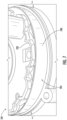
- FIG. 4 shows an enlarged view of the illuminator assembly 301 taken at detail view IV-IV of FIG. 3 .
- the cavity 304 can include a reflecting surface 400 configured to direct light emitted by the optical emitter 305 towards the channels 312. At least a portion of the reflecting surface 400 can extend in a direction of the illuminator optic 300. As shown, at least a portion of the top surface 308 may define at least a portion of the reflecting surface 400.
- the reflecting surface 400 can include at least one arcuate portion.
- the reflecting surface 400 can have a convex shape in a first plane and a concave shape in a second plane.
- the reflecting surface 400 can have a convex shape in a horizontal plane (e.g., a plane generally parallel to a surface to be cleaned) and a concave shape in a vertical plane (e.g., a plane generally perpendicular to the surface to be cleaned).
- the cavity 304 can also include a directing surface 402 configured to direct light emitted by the optical emitter 305 into a respective channel 312. As shown, the directing surface 402 extends in a direction of the reflecting surface 400.
- the directing surface 402 can have a generally triangular shape with one or more planar sides configured to direct light into a respective channel 312.
- the directing surface 402 is positioned opposite the reflecting surface 400 such that at least a portion of the light incident on the reflecting surface 400 is directed generally towards the directing surface 402.
- the reflecting surface 400 and the directing surface 402 can generally be described as cooperating to direct light along respective channels 312 and into the light receiving surface 306 of the illuminator optic 300. At least a portion of the light incident on the light receiving surface 306 may pass into the illuminator optic 300. In some instances, at least a portion of the light incident on the light receiving surface 306 may be reflected from the light receiving surface 306. The reflected light may continue to travel along the respective channel 312. As light reflects along the channel 312, a portion of the light may enter the illuminator optic 300 at different locations along the light receiving surface 306.
- Reflection of light emitted by the optical emitter 305 at least once before entering the illuminator optic 300 may result in the light emitted from the illumination surface 310 having a more uniform appearance (e.g., intensity) when compared to light emitted directly into the illuminator optic 300.
- the cavity 304 and/or the channels 312 can be configured to increase the number of reflections of the emitted light prior to the light entering the illuminator optic 300.
- reflection of the emitted light may prevent the emitted light from directly entering the illuminator optic 300.
- Directly emitting light into the illuminator optic 300 may create a bright spot on the illumination surface 310.
- the directing surface 402 can be positioned such that light emitted from the optical emitter 305 prevents light from being transmitted directly from the optical emitter 305 and into the illuminator optic 300, which may reduce or prevent the appearance of bright spots on the illumination surface 310.
- a portion (e.g., at least 80%, 90%, or 95%) of the illumination surface 310 illuminated by a respective optical emitter 305 may have a substantially uniform intensity (e.g., the illumination intensity varies by less than 5%, 10%, or 15%) over the portion of the illumination surface 310 that is illuminated by the optical emitter 305.
- FIG. 5 shows a cross-sectional view of a portion of a robotic cleaner 500, which may be an example of the robotic cleaner 100 of FIG. 1 .
- the robotic cleaner 500 includes the illuminator assembly 301 of FIG. 3 .
- the optical emitter 305 is coupled to a printed circuit board (PCB) 502 disposed within a body 501 of the robotic cleaner 500 such that the optical emitter 305 is disposed between the PCB 502 and the illumination guide 302 (e.g., such that at least one optical emitter 305 is received within a respective cavity 304).
- PCB printed circuit board
- the PCB 502 can define at least a portion of the cavity 304 such that light emitted from the optical emitter 305 is reflected from the top surface 308 of the cavity 304 towards the PCB 502 such that it can be reflected from the PCB 502. Light reflected from the PCB 502 may be incident on the top surface 308 of the cavity 304 or the light receiving surface 306 of the illuminator optic 300.
- the light receiving surface 306 can extend substantially parallel (e.g., within plus or minus 1°, 2°, 3°, 4°, or 5° of parallel) to an emission axis 504 of the optical emitter 305.
- the emission axis 504 may extend transverse to (e.g., substantially perpendicular to) the light receiving surface 306 (e.g., as shown in FIG. 2 ).
- the illuminator optic 300 can extend within the cavity 304 such that two or more light receiving surfaces 306 are capable of receiving light.
- one or more of the light emitting surfaces 306 can extend substantially parallel (e.g., within plus or minus 1°, 2°, 3°, 4°, or 5° of parallel) to the emission axis 504 of the optical emitter 305 and one or more of the light emitting surfaces 306 can extend transverse to the emission axis 504 of the optical emitter 305.
- Emitted light can generally follow a light path 506 that extends from the optical emitter 305 through the cavity 304 and into the illuminator optic 300.
- the illuminator optic 300 can be configured to encourage the internal reflection of light traveling therein (or passing therethrough).
- the illuminator optic 300 can have one or more sidewalls 508 having a surface polish that encourages reflection.
- one or more outer surfaces of the illuminator optic 300 can have a reflective material (e.g., a paint) applied thereto and/or at least a portion of the robotic cleaner 500 and/or the illumination guide 302 can be reflective (e.g., have a reflective paint applied thereto and/or be made of a reflective material).
- the illuminator optic 300 can also be configured to diffuse the light extending (or passing) therethrough.
- the illuminator optic 300, the illumination guide 302, and/or the optical emitter 305 can be configured such that a portion (e.g., at least 80%, 90%, or 95%) of the illumination surface 310 illuminated by a respective optical emitter 305 may have a substantially uniform intensity (e.g., the illumination intensity varies by less than 5%, 10%, or 15%) over the portion of the illumination surface 310 that is illuminated by the optical emitter 305.
- the illuminator optic 300 can be made of, for example, polycarbonate, glass, acrylic, and/or any other suitable light transmissive material.
- the illumination surface 310 can be textured (e.g., etched) such that the illumination surface 310 encourages diffusion of light passing therethrough.
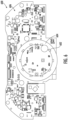
- FIG. 6 shows a top view of a PCB 600, which may be an example of the PCB 502 of FIG. 5 .
- the PCB 600 includes one or more light emitting diodes (LEDs) 602, which may be an example of the optical emitters 305 of FIG. 3 .
- the LEDs 602 have an emission axis that extends transverse to (e.g., substantially perpendicular to) a top surface 606 the PCB 600 such that light is emitted in a direction away from the PCB 600.
- the LEDs 602 are arranged such that an illumination guide (e.g., the illumination guide 302 of FIG. 3 ) can be positioned above the LEDs 602 such that the illumination guide directs light emitted by the LEDs 602 into an illuminator optic (e.g., the illuminator optic 300 of FIG. 3 ).
- an illumination guide e.g., the illumination guide 302 of FIG. 3
- an illuminator optic e.g., the illuminator optic 300 of FIG. 3
- the PCB 600 can include a reflective portion 604 that extends at least partially around each of the LEDs 602.
- the reflective portion 604 can be configured to direct light incident on the reflective portion 604 in a direction away from the PCB 600. As such, reflection within the cavities defined by the illumination guide are encouraged.
- the reflective portion 604 may be applied to the top surface 606 of the PCB 600 using, for example, a silk-screening process.
- the reflective portion 604 may be an adhesive label coupled to the top surface 606, a paint applied to the top surface 606, and/or any other reflective material.
- Each of the LEDs 602 may be individually (or selectively) addressable. As such, the LEDs 602 can be configured to illuminate according to a pattern. By illuminating each of the LEDs 602 individually according to a pattern the illumination surface of the illuminator optic can be illuminated according to different patterns. For example, one or more segments/predetermined portions of the illuminating surface can be illuminated to form a static or moving pattern by individually illuminating respective ones of the LEDs 602 according to a pattern. As such, the illuminator optic can be used to communicate a status of a robotic cleaner (e.g., the robotic cleaner 100 of FIG. 1 ) to a user of the robotic cleaner using the illuminated patterns.
- a robotic cleaner e.g., the robotic cleaner 100 of FIG. 1
- one or more of the LEDs 602 can be bi-colored LEDs (e.g., the LEDs 602 can be red/blue bi-colored LEDs).
- a status of the robotic cleaner can be communicated using a color of the light emitted from the illumination surface of the illuminator optic.
- different colors and/or patterns can be used to indicate a status of the robotic cleaner.
- a sound sequence may be used to communicate a status of the robotic cleaner.
- a sound sequence may be associated with a respective light pattern (e.g., comprising one or more colors and/or illumination patterns).
- FIG. 7 shows a perspective view of a portion of an illuminator assembly 701, which may be an example of the illuminator assembly 301 of FIG. 3 .
- the illuminator assembly 701 includes an illuminator optic 700 and an illumination guide 702.
- the illuminator optic 700 may have a polished exterior surface 704 which is configured to cause light to internally reflect in a direction of the illumination guide 702.
- the exterior surface 704 may have a substantially mirror-like finish.
- the illumination guide 702 can be made of a light reflective material (e.g., a white material) configured to cause light to internally reflect within the illuminator optic 700 in a direction of the exterior surface 704.
- the exterior surface 704 of the illuminator optic 700 and the illumination guide 702 may generally be described as being configured to cause internal reflection of light within the illuminator optic 700.
- FIG. 8 shows a schematic example of an illuminator assembly 800, which may be an example of the illuminator assembly 116 of FIG. 1 , coupled to a printed circuit board (PCB) 802.
- the PCB 802 includes a plurality of light emitting diodes (LEDs) 804 coupled thereto.
- LEDs light emitting diodes
- Each of the LEDs 804 are disposed within a respective cavity 806 defined within an illumination guide 808 such that at least a portion of the light emitted by the LEDs 804 is reflected from a respective reflection surface 810 within the cavity 806.
- each reflection surface 810 is angled relative to an emission axis of corresponding LEDs 804 such that light incident on the reflection surface 810 is directed towards a light receiving surface 812 of an illuminator optic 814. At least a portion of the light incident on the light receiving surface 812 of the illuminator optic 814 may enter the illuminator optic 814 and be emitted from the illuminator optic 814 at an illumination surface 816.
- An example of a robotic cleaner may include a body and an illuminator assembly. At least a portion of the illuminator assembly may be disposed within the body.
- the illuminator assembly may include an illuminator optic configured to emit light from an illumination surface and an illumination guide configured to direct light into the illuminator optic.
- the illumination guide may have a cavity.
- the cavity may include a reflecting surface and a directing surface, the reflecting surface being positioned opposite the directing surface.
- the robotic cleaner may further include a printed circuit board (PCB) that may have one or more optical emitters coupled thereto and the PCB may be disposed within the body such that the one or more optical emitters are received within a respective cavity of the illumination guide.
- the PCB may include a reflective portion configured to extend at least partially around at least one of the one or more optical emitters.
- the robotic cleaner may further include one or more optical emitters that may be horizontally offset from the illuminator optic. In some instances, at least a portion of light emitted from a respective one of the one or more optical emitters may be reflected from a top surface of a respective cavity.
- a light receiving surface of the illuminator optic may extend substantially parallel to an emission axis of an optical emitter configured to emit light into the cavity.
- the illuminator optic may be annular.
- the illuminator optic may be configured to encourage internal reflection of light passing therethrough.
- the illuminator optic may be configured to diffuse light passing therethrough.
- a robotic cleaner may include a body, at least one wheel coupled to the body, at least one drive motor configured to cause a corresponding wheel to rotate, an illuminator assembly, wherein at least a portion of the illuminator assembly may be disposed within the body, and a printed circuit board (PCB) having one or more light emitting diodes (LEDs) coupled thereto.
- the illuminator assembly may include an illuminator optic configured to emit light from an illumination surface and an illumination guide configured to direct light into the illuminator optic.
- the PCB may be disposed within the body such that the one or more LEDs are received within a respective cavity defined within the illumination guide, wherein an emission axis of a respective one of the one or more LEDs extends substantially parallel to a light receiving surface of the illuminator optic.
- the PCB may include a reflective portion configured to extend at least partially around at least one of the one or more LEDs. In some instances, at least a portion of light emitted from a respective one of the one or more LEDs may be reflected from a top surface of a respective cavity.
- each cavity may include a reflecting surface and a directing surface, the reflecting surface and the directing surface being configured to cooperate to direct light emitted by a respective LED to the light receiving surface of the illuminator optic.
- the illuminator optic may be annular. In some instances, the illuminator optic may be configured to encourage internal reflection of light passing therethrough. In some instances, the illuminator optic may be configured to diffuse light passing therethrough.
- An example of an illuminator assembly may include an illuminator optic configured to emit light from an illumination surface and an illumination guide configured to direct light into the illuminator optic.
- the illumination guide may have a cavity configured to receive an optical emitter.
- the cavity may include a reflecting surface and a directing surface, the reflecting surface and the directing surface being configured to cooperate to direct light emitted by the optical emitter to a light receiving surface of the illuminator optic.
- a light receiving surface of the illuminator optic may extend substantially parallel to an emission axis of the optical emitter.
- the illuminator optic may be annular.
- the illuminator optic may be configured to encourage internal reflection of light passing therethrough.
- the illuminator assembly can be used with any device where communication using a color and/or light pattern may be desirable.
- the illuminator assembly may be used with an upright vacuum cleaner, a docking station for a robotic cleaner, appliances (e.g., washer/dryers, kitchen stoves/ovens, and/or any other appliance), audio/video equipment (e.g., televisions, stereos, smart speakers, and/or any other audio/video equipment), and/or any other device.
- appliances e.g., washer/dryers, kitchen stoves/ovens, and/or any other appliance
- audio/video equipment e.g., televisions, stereos, smart speakers, and/or any other audio/video equipment
Landscapes
- Physics & Mathematics (AREA)
- General Physics & Mathematics (AREA)
- Optics & Photonics (AREA)
- Engineering & Computer Science (AREA)
- Mechanical Engineering (AREA)
- Electric Vacuum Cleaner (AREA)
- Non-Portable Lighting Devices Or Systems Thereof (AREA)
Claims (9)
- Reinigungsroboter (100, 500), umfassend:einen Körper (102, 501); undeine Beleuchtungsbaugruppe (116, 301), wobei mindestens ein Abschnitt der Beleuchtungsbaugruppe innerhalb des Körpers angeordnet ist, wobei die Beleuchtungsbaugruppe Folgendes umfasst:einen oder mehrere optische Emitter (200, 305);eine Beleuchtungsoptik (201, 300), die eine Lichtaufnahmefläche (204, 306) und eine Beleuchtungsfläche (208, 310) aufweist, wobei die Beleuchtungsfläche dazu konfiguriert ist, Licht zu emittieren, das durch den einen oder die mehreren optischen Emittern generiert wird; undeine Beleuchtungsführung (302), die dazu konfiguriert ist, Licht, das durch den einen oder die mehreren optischen Emitter generiert wird, in die Lichtaufnahmefläche (204, 306) der Beleuchtungsoptik (201, 300) leiten, dadurch gekennzeichnet, dass die Beleuchtungsführung Folgendes aufweist:einen leeren Hohlraum (304), der dazu konfiguriert ist, einen entsprechenden optischen Emitter (200, 305) aufzunehmen, sodass mindestens ein Teil des Lichts, das von dem entsprechenden optischen Emitter (200, 305) emittiert wird, innerhalb des Hohlraums reflektiert wird, wobei der Hohlraum eine Reflexionsfläche (400) und eine Leitfläche (402) beinhaltet, die Reflexionsfläche (400) einen gebogenen Abschnitt aufweist, der sich in einer Richtung der Leitfläche (402) erstreckt, und die Leitfläche (402) eine im Wesentlichen dreieckige Form aufweist, die sich in einer Richtung der Reflexionsfläche (400) erstreckt und die Reflexionsfläche (400) gegenüber der Leitfläche (402) positioniert ist, sodass auf die Reflexionsfläche (400) einfallendes Licht im Allgemeinen in Richtung der Leitfläche (402) geleitet wird; undeinen Kanal (312), der die Lichtaufnahmefläche (204, 306) optisch an den Hohlraum koppelt, wobei die Reflexionsfläche (400) und die Leitfläche (402) zusammenwirken, um Licht in den Kanal (312) zu leiten, wobei der Kanal (312) dazu konfiguriert ist, im Allgemeinen zu verhindern, dass Licht, das durch den einen oder die mehreren optischen Emitter (200, 305) emittiert wird, direkt auf die Lichtaufnahmefläche (204, 306) trifft, indem eine Anzahl an Reflexionen von Licht, das durch den einen oder die mehreren optischen Emitter (200, 305) emittiert wird, vor dem Auftreffen des Lichts auf die Lichtaufnahmefläche (204, 306) erhöht wird.
- Reinigungsroboter nach Anspruch 1, ferner umfassend eine Leiterplatte (PCB) (502), die den einen oder die mehreren Emitter (200, 305) daran gekoppelt aufweist, wobei die PCB derart innerhalb des Körpers (102, 501) angeordnet ist, dass der eine oder die mehreren optischen Emitter innerhalb eines jeweiligen Hohlraums (304) der Beleuchtungsführung (302) aufgenommen sind.
- Reinigungsroboter nach Anspruch 2, wobei die PCB (502) einen Reflexionsabschnitt beinhaltet, der dazu konfiguriert ist, sich mindestens teilweise um mindestens eine des einen oder der mehreren optischen Emitter (200, 305) zu erstrecken.
- Reinigungsroboter nach Anspruch 1, wobei der eine oder die mehreren optischen Emitter (200, 305) horizontal von der Beleuchtungsoptik (201, 300) versetzt sind.
- Reinigungsroboter nach Anspruch 4, wobei mindestens ein Teil des Lichts, das von einem jeweiligen der einen oder mehreren optischen Emittern (200, 305) emittiert wird, von einer Oberseitenfläche (308) eines jeweiligen Hohlraums (308) reflektiert wird.
- Reinigungsroboter nach Anspruch 1, wobei sich die Lichtaufnahmefläche (204, 306) des Beleuchtungsoptik (201, 300) im Wesentlichen parallel zu einer Emissionsachse (203, 504) des einen oder der mehreren optischen Emitter (200, 305), die dazu konfiguriert sind, Licht in den Hohlraum (308) zu emittieren, erstreckt.
- Reinigungsroboter nach Anspruch 1, wobei die Beleuchtungsoptik (201, 300) ringförmig ist.
- Reinigungsroboter nach Anspruch 1, wobei die Beleuchtungsoptik (201, 300) dazu konfiguriert ist, interne Reflexion von dahindurchgehendem Licht zu verursachen.
- Reinigungsroboter nach Anspruch 1, wobei die Beleuchtungsoptik (201, 300) dazu konfiguriert ist, dahindurchgehendes Licht zu streuen.
Applications Claiming Priority (2)
| Application Number | Priority Date | Filing Date | Title |
|---|---|---|---|
| US201862756752P | 2018-11-07 | 2018-11-07 | |
| PCT/US2019/060228 WO2020097304A1 (en) | 2018-11-07 | 2019-11-07 | Illuminator optic for robotic cleaner |
Publications (3)
| Publication Number | Publication Date |
|---|---|
| EP3877792A1 EP3877792A1 (de) | 2021-09-15 |
| EP3877792A4 EP3877792A4 (de) | 2022-11-02 |
| EP3877792B1 true EP3877792B1 (de) | 2024-06-19 |
Family
ID=70459930
Family Applications (1)
| Application Number | Title | Priority Date | Filing Date |
|---|---|---|---|
| EP19883158.8A Active EP3877792B1 (de) | 2018-11-07 | 2019-11-07 | Beleuchtungsoptik für reinigungsroboter |
Country Status (4)
| Country | Link |
|---|---|
| US (1) | US11000169B2 (de) |
| EP (1) | EP3877792B1 (de) |
| CN (2) | CN212368885U (de) |
| WO (1) | WO2020097304A1 (de) |
Families Citing this family (27)
| Publication number | Priority date | Publication date | Assignee | Title |
|---|---|---|---|---|
| US12622553B2 (en) | 2019-10-18 | 2026-05-12 | Sharkninja Operating Llc | Agitator for a surface treatment apparatus and a surface treatment apparatus having the same |
| US11647881B2 (en) | 2015-10-21 | 2023-05-16 | Sharkninja Operating Llc | Cleaning apparatus with combing unit for removing debris from cleaning roller |
| US10925447B2 (en) | 2017-03-10 | 2021-02-23 | Sharkninja Operating Llc | Agitator with debrider and hair removal |
| US11202542B2 (en) | 2017-05-25 | 2021-12-21 | Sharkninja Operating Llc | Robotic cleaner with dual cleaning rollers |
| US11672388B2 (en) | 2017-09-22 | 2023-06-13 | Sharkninja Operating Llc | Hand-held surface cleaning device |
| CN115089055B (zh) | 2018-07-20 | 2024-02-13 | 尚科宁家运营有限公司 | 用于机器人清洁器的对接站和清洁系统 |
| US11399675B2 (en) | 2018-07-31 | 2022-08-02 | Sharkninja Operating Llc | Upright surface treatment apparatus having removable pod |
| WO2020223619A1 (en) | 2019-05-01 | 2020-11-05 | Sharkninja Operating Llc | Vacuum cleaner and docking station for use with the same |
| WO2021007568A1 (en) | 2019-07-11 | 2021-01-14 | Sharkninja Operating Llc | Smart nozzle and a surface cleaning device implementing same |
| WO2021207139A1 (en) | 2020-04-06 | 2021-10-14 | Sharkninja Operating Llc | Allergen reduction device |
| CN115397677B (zh) | 2020-04-13 | 2025-07-01 | 尚科宁家运营有限公司 | 脚轮锁定装置以及实施所述脚轮锁定装置的表面清洁设备 |
| US12635839B2 (en) | 2020-06-12 | 2026-05-26 | Sharkninja Operating Llc | Robotic cleaner having surface type sensor |
| JP7553695B2 (ja) | 2020-07-29 | 2024-09-18 | シャークニンジャ オペレーティング エルエルシー | 表面処理装置のためのノズルおよび同ノズルを有する表面処理装置 |
| US12342982B2 (en) | 2021-04-12 | 2025-07-01 | Sharkninja Operating Llc | Robotic cleaner |
| US12339324B2 (en) | 2021-04-23 | 2025-06-24 | Sharkninja Operating Llc | Determining state of charge for battery powered devices including battery powered surface treatment apparatuses |
| CN219438963U (zh) | 2021-06-29 | 2023-08-01 | 尚科宁家运营有限公司 | 机器人清洁器及其抽吸电机空气管道 |
| US20230043567A1 (en) | 2021-08-03 | 2023-02-09 | Sharkninja Operating Llc | Surface cleaning device with odor management |
| US12433461B2 (en) | 2022-07-05 | 2025-10-07 | Sharkninja Operating Llc | Vacuum cleaner |
| US12376722B2 (en) | 2021-08-13 | 2025-08-05 | Sharkninja Operating Llc | Robotic cleaner |
| CN117940051A (zh) | 2021-09-07 | 2024-04-26 | 尚科宁家运营有限公司 | 机器人清洁器 |
| CN118201538A (zh) | 2021-11-05 | 2024-06-14 | 尚科宁家运营有限公司 | 具有气味控制的表面清洁装置 |
| WO2023200853A2 (en) | 2022-04-12 | 2023-10-19 | Sharkninja Operating Llc | Robotic cleaner and methods of operating the same |
| US12329350B2 (en) | 2022-05-09 | 2025-06-17 | Sharkninja Operating Llc | Robotic cleaner |
| WO2024011479A1 (en) | 2022-07-14 | 2024-01-18 | Sharkninja Operating Llc | Robotic cleaner |
| BE1030924B1 (de) * | 2022-09-29 | 2024-04-29 | Miele & Cie | Beleuchtungseinrichtung für einen Staubsauger |
| EP4698028A1 (de) * | 2023-04-20 | 2026-02-25 | SharkNinja Operating LLC | System und verfahren zur erkennung von wänden oder objekten in einer bestimmten nähe einer vakuumbodendüse |
| US12654932B2 (en) | 2023-09-13 | 2026-06-16 | Sharkninja Operating Llc | Robotic cleaner debris removal integrated docking station |
Family Cites Families (12)
| Publication number | Priority date | Publication date | Assignee | Title |
|---|---|---|---|---|
| WO1993003399A1 (en) * | 1991-08-07 | 1993-02-18 | Aktiebolaget Electrolux | Obstacle detecting assembly |
| US20080260328A1 (en) * | 2007-04-20 | 2008-10-23 | 3M Innovative Properties Company | Led light extraction bar and injection optic for thin lightguide |
| TWI454639B (zh) | 2009-12-28 | 2014-10-01 | Hon Hai Prec Ind Co Ltd | 環形導光結構及採用該環形導光結構之背光模組 |
| KR101487778B1 (ko) * | 2010-05-11 | 2015-01-29 | 삼성전자 주식회사 | 센싱 시스템 및 이를 갖춘 이동 로봇 |
| JP5749576B2 (ja) * | 2011-06-07 | 2015-07-15 | 株式会社小糸製作所 | 車両用灯具 |
| US10030846B2 (en) * | 2012-02-14 | 2018-07-24 | Svv Technology Innovations, Inc. | Face-lit waveguide illumination systems |
| KR101490170B1 (ko) * | 2013-03-05 | 2015-02-05 | 엘지전자 주식회사 | 로봇 청소기 |
| US9721586B1 (en) | 2013-03-14 | 2017-08-01 | Amazon Technologies, Inc. | Voice controlled assistant with light indicator |
| US10001592B2 (en) * | 2013-11-22 | 2018-06-19 | Lumens Co., Ltd. | Backlight unit, double cone-shaped reflector, double cone-shaped reflector strip, illumination apparatus, and method of manufacturing double cone-shaped reflector |
| US9574762B1 (en) | 2014-09-30 | 2017-02-21 | Amazon Technologies, Inc. | Light assemblies for electronic devices containing audio circuitry |
| JP6689000B2 (ja) | 2014-11-10 | 2020-04-28 | パナソニックIpマネジメント株式会社 | 掃除機用照明装置 |
| US10272828B2 (en) * | 2016-08-16 | 2019-04-30 | Irobot Corporation | Light indicator system for an autonomous mobile robot |
-
2019
- 2019-11-06 CN CN201921908077.3U patent/CN212368885U/zh active Active
- 2019-11-07 WO PCT/US2019/060228 patent/WO2020097304A1/en not_active Ceased
- 2019-11-07 EP EP19883158.8A patent/EP3877792B1/de active Active
- 2019-11-07 CN CN201980087995.0A patent/CN113260887B/zh active Active
- 2019-11-07 US US16/676,811 patent/US11000169B2/en active Active
Also Published As
| Publication number | Publication date |
|---|---|
| CN113260887B (zh) | 2023-03-03 |
| EP3877792A1 (de) | 2021-09-15 |
| US20200138260A1 (en) | 2020-05-07 |
| EP3877792A4 (de) | 2022-11-02 |
| US11000169B2 (en) | 2021-05-11 |
| CN212368885U (zh) | 2021-01-19 |
| CN113260887A (zh) | 2021-08-13 |
| WO2020097304A1 (en) | 2020-05-14 |
Similar Documents
| Publication | Publication Date | Title |
|---|---|---|
| US11000169B2 (en) | Illuminator optic for robotic cleaner | |
| US9594204B2 (en) | Lighting device for vacuum cleaner | |
| US5207498A (en) | Vacuum cleaner headlight | |
| US5107565A (en) | Light system for vacuum cleaner | |
| CN110300950B (zh) | 触摸感测系统中的光学耦合 | |
| US11460168B2 (en) | Lamp | |
| US7696984B2 (en) | Miniaturized optical mouse core | |
| WO2015119827A1 (en) | Light assembly with light guide | |
| JP5200862B2 (ja) | 天井扇風機 | |
| JP6138644B2 (ja) | 照明装置 | |
| JP2017126586A (ja) | 照明装置 | |
| JP2014017182A (ja) | 照明装置 | |
| US7806582B2 (en) | Illuminating module for mounting in a domestic appliance and domestic appliance with such a module | |
| KR101502047B1 (ko) | 엘이디 평판조명모듈 | |
| WO2017061557A1 (ja) | 照明装置 | |
| JP2015111520A (ja) | 照光装置 | |
| CN213524986U (zh) | 清洁机器人的发光组件及清洁机器人 | |
| CN213640735U (zh) | 一种清洁设备附件及具有其的清洁设备 | |
| US11007930B2 (en) | Lighting device | |
| CN223088123U (zh) | 用于家用电器的门体和家用电器 | |
| CN213524980U (zh) | 面盖组件和清洁机器人 | |
| CN110693392A (zh) | 手持式吸尘器 | |
| KR101405046B1 (ko) | 분리형 가이드 패널 및 이를 갖는 측면 조광형 백라이트 장치 | |
| CN113291217B (zh) | 杯架 | |
| CN215636782U (zh) | 一种阅读灯具及其车辆 |
Legal Events
| Date | Code | Title | Description |
|---|---|---|---|
| STAA | Information on the status of an ep patent application or granted ep patent |
Free format text: STATUS: THE INTERNATIONAL PUBLICATION HAS BEEN MADE |
|
| PUAI | Public reference made under article 153(3) epc to a published international application that has entered the european phase |
Free format text: ORIGINAL CODE: 0009012 |
|
| STAA | Information on the status of an ep patent application or granted ep patent |
Free format text: STATUS: REQUEST FOR EXAMINATION WAS MADE |
|
| 17P | Request for examination filed |
Effective date: 20210521 |
|
| AK | Designated contracting states |
Kind code of ref document: A1 Designated state(s): AL AT BE BG CH CY CZ DE DK EE ES FI FR GB GR HR HU IE IS IT LI LT LU LV MC MK MT NL NO PL PT RO RS SE SI SK SM TR |
|
| DAV | Request for validation of the european patent (deleted) | ||
| DAX | Request for extension of the european patent (deleted) | ||
| A4 | Supplementary search report drawn up and despatched |
Effective date: 20220929 |
|
| RIC1 | Information provided on ipc code assigned before grant |
Ipc: F21V 7/00 20060101ALI20220923BHEP Ipc: F21K 9/61 20160101ALI20220923BHEP Ipc: A47L 11/00 20060101ALI20220923BHEP Ipc: A47L 9/30 20060101ALI20220923BHEP Ipc: G03B 21/14 20060101ALI20220923BHEP Ipc: G03B 21/20 20060101ALI20220923BHEP Ipc: G03B 21/00 20060101ALI20220923BHEP Ipc: G02B 6/00 20060101AFI20220923BHEP |
|
| STAA | Information on the status of an ep patent application or granted ep patent |
Free format text: STATUS: EXAMINATION IS IN PROGRESS |
|
| 17Q | First examination report despatched |
Effective date: 20230725 |
|
| GRAP | Despatch of communication of intention to grant a patent |
Free format text: ORIGINAL CODE: EPIDOSNIGR1 |
|
| STAA | Information on the status of an ep patent application or granted ep patent |
Free format text: STATUS: GRANT OF PATENT IS INTENDED |
|
| INTG | Intention to grant announced |
Effective date: 20240311 |
|
| GRAS | Grant fee paid |
Free format text: ORIGINAL CODE: EPIDOSNIGR3 |
|
| GRAA | (expected) grant |
Free format text: ORIGINAL CODE: 0009210 |
|
| STAA | Information on the status of an ep patent application or granted ep patent |
Free format text: STATUS: THE PATENT HAS BEEN GRANTED |
|
| AK | Designated contracting states |
Kind code of ref document: B1 Designated state(s): AL AT BE BG CH CY CZ DE DK EE ES FI FR GB GR HR HU IE IS IT LI LT LU LV MC MK MT NL NO PL PT RO RS SE SI SK SM TR |
|
| REG | Reference to a national code |
Ref country code: GB Ref legal event code: FG4D |
|
| REG | Reference to a national code |
Ref country code: CH Ref legal event code: EP |
|
| REG | Reference to a national code |
Ref country code: DE Ref legal event code: R096 Ref document number: 602019054015 Country of ref document: DE |
|
| PG25 | Lapsed in a contracting state [announced via postgrant information from national office to epo] |
Ref country code: BG Free format text: LAPSE BECAUSE OF FAILURE TO SUBMIT A TRANSLATION OF THE DESCRIPTION OR TO PAY THE FEE WITHIN THE PRESCRIBED TIME-LIMIT Effective date: 20240619 |
|
| PG25 | Lapsed in a contracting state [announced via postgrant information from national office to epo] |
Ref country code: FI Free format text: LAPSE BECAUSE OF FAILURE TO SUBMIT A TRANSLATION OF THE DESCRIPTION OR TO PAY THE FEE WITHIN THE PRESCRIBED TIME-LIMIT Effective date: 20240619 Ref country code: HR Free format text: LAPSE BECAUSE OF FAILURE TO SUBMIT A TRANSLATION OF THE DESCRIPTION OR TO PAY THE FEE WITHIN THE PRESCRIBED TIME-LIMIT Effective date: 20240619 |
|
| REG | Reference to a national code |
Ref country code: LT Ref legal event code: MG9D |
|
| PG25 | Lapsed in a contracting state [announced via postgrant information from national office to epo] |
Ref country code: GR Free format text: LAPSE BECAUSE OF FAILURE TO SUBMIT A TRANSLATION OF THE DESCRIPTION OR TO PAY THE FEE WITHIN THE PRESCRIBED TIME-LIMIT Effective date: 20240920 |
|
| REG | Reference to a national code |
Ref country code: NL Ref legal event code: MP Effective date: 20240619 |
|
| PG25 | Lapsed in a contracting state [announced via postgrant information from national office to epo] |
Ref country code: LV Free format text: LAPSE BECAUSE OF FAILURE TO SUBMIT A TRANSLATION OF THE DESCRIPTION OR TO PAY THE FEE WITHIN THE PRESCRIBED TIME-LIMIT Effective date: 20240619 |
|
| PG25 | Lapsed in a contracting state [announced via postgrant information from national office to epo] |
Ref country code: NO Free format text: LAPSE BECAUSE OF FAILURE TO SUBMIT A TRANSLATION OF THE DESCRIPTION OR TO PAY THE FEE WITHIN THE PRESCRIBED TIME-LIMIT Effective date: 20240919 Ref country code: LV Free format text: LAPSE BECAUSE OF FAILURE TO SUBMIT A TRANSLATION OF THE DESCRIPTION OR TO PAY THE FEE WITHIN THE PRESCRIBED TIME-LIMIT Effective date: 20240619 Ref country code: HR Free format text: LAPSE BECAUSE OF FAILURE TO SUBMIT A TRANSLATION OF THE DESCRIPTION OR TO PAY THE FEE WITHIN THE PRESCRIBED TIME-LIMIT Effective date: 20240619 Ref country code: GR Free format text: LAPSE BECAUSE OF FAILURE TO SUBMIT A TRANSLATION OF THE DESCRIPTION OR TO PAY THE FEE WITHIN THE PRESCRIBED TIME-LIMIT Effective date: 20240920 Ref country code: FI Free format text: LAPSE BECAUSE OF FAILURE TO SUBMIT A TRANSLATION OF THE DESCRIPTION OR TO PAY THE FEE WITHIN THE PRESCRIBED TIME-LIMIT Effective date: 20240619 Ref country code: BG Free format text: LAPSE BECAUSE OF FAILURE TO SUBMIT A TRANSLATION OF THE DESCRIPTION OR TO PAY THE FEE WITHIN THE PRESCRIBED TIME-LIMIT Effective date: 20240619 Ref country code: RS Free format text: LAPSE BECAUSE OF FAILURE TO SUBMIT A TRANSLATION OF THE DESCRIPTION OR TO PAY THE FEE WITHIN THE PRESCRIBED TIME-LIMIT Effective date: 20240919 |
|
| PG25 | Lapsed in a contracting state [announced via postgrant information from national office to epo] |
Ref country code: NL Free format text: LAPSE BECAUSE OF FAILURE TO SUBMIT A TRANSLATION OF THE DESCRIPTION OR TO PAY THE FEE WITHIN THE PRESCRIBED TIME-LIMIT Effective date: 20240619 |
|
| REG | Reference to a national code |
Ref country code: AT Ref legal event code: MK05 Ref document number: 1696270 Country of ref document: AT Kind code of ref document: T Effective date: 20240619 |
|
| PG25 | Lapsed in a contracting state [announced via postgrant information from national office to epo] |
Ref country code: NL Free format text: LAPSE BECAUSE OF FAILURE TO SUBMIT A TRANSLATION OF THE DESCRIPTION OR TO PAY THE FEE WITHIN THE PRESCRIBED TIME-LIMIT Effective date: 20240619 |
|
| PG25 | Lapsed in a contracting state [announced via postgrant information from national office to epo] |
Ref country code: PT Free format text: LAPSE BECAUSE OF FAILURE TO SUBMIT A TRANSLATION OF THE DESCRIPTION OR TO PAY THE FEE WITHIN THE PRESCRIBED TIME-LIMIT Effective date: 20241021 |
|
| PG25 | Lapsed in a contracting state [announced via postgrant information from national office to epo] |
Ref country code: PT Free format text: LAPSE BECAUSE OF FAILURE TO SUBMIT A TRANSLATION OF THE DESCRIPTION OR TO PAY THE FEE WITHIN THE PRESCRIBED TIME-LIMIT Effective date: 20241021 |
|
| PG25 | Lapsed in a contracting state [announced via postgrant information from national office to epo] |
Ref country code: PL Free format text: LAPSE BECAUSE OF FAILURE TO SUBMIT A TRANSLATION OF THE DESCRIPTION OR TO PAY THE FEE WITHIN THE PRESCRIBED TIME-LIMIT Effective date: 20240619 |
|
| PG25 | Lapsed in a contracting state [announced via postgrant information from national office to epo] |
Ref country code: EE Free format text: LAPSE BECAUSE OF FAILURE TO SUBMIT A TRANSLATION OF THE DESCRIPTION OR TO PAY THE FEE WITHIN THE PRESCRIBED TIME-LIMIT Effective date: 20240619 |
|
| PG25 | Lapsed in a contracting state [announced via postgrant information from national office to epo] |
Ref country code: AT Free format text: LAPSE BECAUSE OF FAILURE TO SUBMIT A TRANSLATION OF THE DESCRIPTION OR TO PAY THE FEE WITHIN THE PRESCRIBED TIME-LIMIT Effective date: 20240619 Ref country code: IS Free format text: LAPSE BECAUSE OF FAILURE TO SUBMIT A TRANSLATION OF THE DESCRIPTION OR TO PAY THE FEE WITHIN THE PRESCRIBED TIME-LIMIT Effective date: 20241019 |
|
| PG25 | Lapsed in a contracting state [announced via postgrant information from national office to epo] |
Ref country code: CZ Free format text: LAPSE BECAUSE OF FAILURE TO SUBMIT A TRANSLATION OF THE DESCRIPTION OR TO PAY THE FEE WITHIN THE PRESCRIBED TIME-LIMIT Effective date: 20240619 |
|
| PG25 | Lapsed in a contracting state [announced via postgrant information from national office to epo] |
Ref country code: SK Free format text: LAPSE BECAUSE OF FAILURE TO SUBMIT A TRANSLATION OF THE DESCRIPTION OR TO PAY THE FEE WITHIN THE PRESCRIBED TIME-LIMIT Effective date: 20240619 Ref country code: RO Free format text: LAPSE BECAUSE OF FAILURE TO SUBMIT A TRANSLATION OF THE DESCRIPTION OR TO PAY THE FEE WITHIN THE PRESCRIBED TIME-LIMIT Effective date: 20240619 |
|
| PG25 | Lapsed in a contracting state [announced via postgrant information from national office to epo] |
Ref country code: ES Free format text: LAPSE BECAUSE OF FAILURE TO SUBMIT A TRANSLATION OF THE DESCRIPTION OR TO PAY THE FEE WITHIN THE PRESCRIBED TIME-LIMIT Effective date: 20240619 Ref country code: SM Free format text: LAPSE BECAUSE OF FAILURE TO SUBMIT A TRANSLATION OF THE DESCRIPTION OR TO PAY THE FEE WITHIN THE PRESCRIBED TIME-LIMIT Effective date: 20240619 |
|
| PG25 | Lapsed in a contracting state [announced via postgrant information from national office to epo] |
Ref country code: SM Free format text: LAPSE BECAUSE OF FAILURE TO SUBMIT A TRANSLATION OF THE DESCRIPTION OR TO PAY THE FEE WITHIN THE PRESCRIBED TIME-LIMIT Effective date: 20240619 Ref country code: SK Free format text: LAPSE BECAUSE OF FAILURE TO SUBMIT A TRANSLATION OF THE DESCRIPTION OR TO PAY THE FEE WITHIN THE PRESCRIBED TIME-LIMIT Effective date: 20240619 Ref country code: RO Free format text: LAPSE BECAUSE OF FAILURE TO SUBMIT A TRANSLATION OF THE DESCRIPTION OR TO PAY THE FEE WITHIN THE PRESCRIBED TIME-LIMIT Effective date: 20240619 Ref country code: PL Free format text: LAPSE BECAUSE OF FAILURE TO SUBMIT A TRANSLATION OF THE DESCRIPTION OR TO PAY THE FEE WITHIN THE PRESCRIBED TIME-LIMIT Effective date: 20240619 Ref country code: IS Free format text: LAPSE BECAUSE OF FAILURE TO SUBMIT A TRANSLATION OF THE DESCRIPTION OR TO PAY THE FEE WITHIN THE PRESCRIBED TIME-LIMIT Effective date: 20241019 Ref country code: ES Free format text: LAPSE BECAUSE OF FAILURE TO SUBMIT A TRANSLATION OF THE DESCRIPTION OR TO PAY THE FEE WITHIN THE PRESCRIBED TIME-LIMIT Effective date: 20240619 Ref country code: EE Free format text: LAPSE BECAUSE OF FAILURE TO SUBMIT A TRANSLATION OF THE DESCRIPTION OR TO PAY THE FEE WITHIN THE PRESCRIBED TIME-LIMIT Effective date: 20240619 Ref country code: CZ Free format text: LAPSE BECAUSE OF FAILURE TO SUBMIT A TRANSLATION OF THE DESCRIPTION OR TO PAY THE FEE WITHIN THE PRESCRIBED TIME-LIMIT Effective date: 20240619 Ref country code: AT Free format text: LAPSE BECAUSE OF FAILURE TO SUBMIT A TRANSLATION OF THE DESCRIPTION OR TO PAY THE FEE WITHIN THE PRESCRIBED TIME-LIMIT Effective date: 20240619 |
|
| PG25 | Lapsed in a contracting state [announced via postgrant information from national office to epo] |
Ref country code: IT Free format text: LAPSE BECAUSE OF FAILURE TO SUBMIT A TRANSLATION OF THE DESCRIPTION OR TO PAY THE FEE WITHIN THE PRESCRIBED TIME-LIMIT Effective date: 20240619 |
|
| REG | Reference to a national code |
Ref country code: DE Ref legal event code: R097 Ref document number: 602019054015 Country of ref document: DE |
|
| PG25 | Lapsed in a contracting state [announced via postgrant information from national office to epo] |
Ref country code: DK Free format text: LAPSE BECAUSE OF FAILURE TO SUBMIT A TRANSLATION OF THE DESCRIPTION OR TO PAY THE FEE WITHIN THE PRESCRIBED TIME-LIMIT Effective date: 20240619 |
|
| PLBE | No opposition filed within time limit |
Free format text: ORIGINAL CODE: 0009261 |
|
| STAA | Information on the status of an ep patent application or granted ep patent |
Free format text: STATUS: NO OPPOSITION FILED WITHIN TIME LIMIT |
|
| 26N | No opposition filed |
Effective date: 20250320 |
|
| REG | Reference to a national code |
Ref country code: CH Ref legal event code: PL |
|
| PG25 | Lapsed in a contracting state [announced via postgrant information from national office to epo] |
Ref country code: MC Free format text: LAPSE BECAUSE OF FAILURE TO SUBMIT A TRANSLATION OF THE DESCRIPTION OR TO PAY THE FEE WITHIN THE PRESCRIBED TIME-LIMIT Effective date: 20240619 |
|
| PG25 | Lapsed in a contracting state [announced via postgrant information from national office to epo] |
Ref country code: LU Free format text: LAPSE BECAUSE OF NON-PAYMENT OF DUE FEES Effective date: 20241107 |
|
| REG | Reference to a national code |
Ref country code: CH Ref legal event code: PL |
|
| PG25 | Lapsed in a contracting state [announced via postgrant information from national office to epo] |
Ref country code: CH Free format text: LAPSE BECAUSE OF NON-PAYMENT OF DUE FEES Effective date: 20241130 |
|
| REG | Reference to a national code |
Ref country code: BE Ref legal event code: MM Effective date: 20241130 |
|
| PG25 | Lapsed in a contracting state [announced via postgrant information from national office to epo] |
Ref country code: SE Free format text: LAPSE BECAUSE OF FAILURE TO SUBMIT A TRANSLATION OF THE DESCRIPTION OR TO PAY THE FEE WITHIN THE PRESCRIBED TIME-LIMIT Effective date: 20240619 |
|
| PG25 | Lapsed in a contracting state [announced via postgrant information from national office to epo] |
Ref country code: BE Free format text: LAPSE BECAUSE OF NON-PAYMENT OF DUE FEES Effective date: 20241130 |
|
| PGFP | Annual fee paid to national office [announced via postgrant information from national office to epo] |
Ref country code: GB Payment date: 20250918 Year of fee payment: 7 |
|
| PG25 | Lapsed in a contracting state [announced via postgrant information from national office to epo] |
Ref country code: FR Free format text: LAPSE BECAUSE OF NON-PAYMENT OF DUE FEES Effective date: 20241130 |
|
| PG25 | Lapsed in a contracting state [announced via postgrant information from national office to epo] |
Ref country code: IE Free format text: LAPSE BECAUSE OF NON-PAYMENT OF DUE FEES Effective date: 20241107 |
|
| PGFP | Annual fee paid to national office [announced via postgrant information from national office to epo] |
Ref country code: DE Payment date: 20250910 Year of fee payment: 7 |
|
| PG25 | Lapsed in a contracting state [announced via postgrant information from national office to epo] |
Ref country code: HU Free format text: LAPSE BECAUSE OF FAILURE TO SUBMIT A TRANSLATION OF THE DESCRIPTION OR TO PAY THE FEE WITHIN THE PRESCRIBED TIME-LIMIT; INVALID AB INITIO Effective date: 20191107 |
|
| PG25 | Lapsed in a contracting state [announced via postgrant information from national office to epo] |
Ref country code: CY Free format text: LAPSE BECAUSE OF FAILURE TO SUBMIT A TRANSLATION OF THE DESCRIPTION OR TO PAY THE FEE WITHIN THE PRESCRIBED TIME-LIMIT; INVALID AB INITIO Effective date: 20191107 |
|
| PG25 | Lapsed in a contracting state [announced via postgrant information from national office to epo] |
Ref country code: TR Free format text: LAPSE BECAUSE OF FAILURE TO SUBMIT A TRANSLATION OF THE DESCRIPTION OR TO PAY THE FEE WITHIN THE PRESCRIBED TIME-LIMIT Effective date: 20240619 |
|
| PG25 | Lapsed in a contracting state [announced via postgrant information from national office to epo] |
Ref country code: SI Free format text: LAPSE BECAUSE OF FAILURE TO SUBMIT A TRANSLATION OF THE DESCRIPTION OR TO PAY THE FEE WITHIN THE PRESCRIBED TIME-LIMIT Effective date: 20240619 |
|
| PG25 | Lapsed in a contracting state [announced via postgrant information from national office to epo] |
Ref country code: LT Free format text: LAPSE BECAUSE OF FAILURE TO SUBMIT A TRANSLATION OF THE DESCRIPTION OR TO PAY THE FEE WITHIN THE PRESCRIBED TIME-LIMIT Effective date: 20240619 |