EP3877793B1 - Systeme comprenant une fibre optique et son procédé d'utilisation - Google Patents
Systeme comprenant une fibre optique et son procédé d'utilisation Download PDFInfo
- Publication number
- EP3877793B1 EP3877793B1 EP19835998.6A EP19835998A EP3877793B1 EP 3877793 B1 EP3877793 B1 EP 3877793B1 EP 19835998 A EP19835998 A EP 19835998A EP 3877793 B1 EP3877793 B1 EP 3877793B1
- Authority
- EP
- European Patent Office
- Prior art keywords
- cladding
- waveguide
- attenuating
- optical fiber
- disposed around
- Prior art date
- Legal status (The legal status is an assumption and is not a legal conclusion. Google has not performed a legal analysis and makes no representation as to the accuracy of the status listed.)
- Active
Links
Images



Classifications
-
- G—PHYSICS
- G02—OPTICS
- G02B—OPTICAL ELEMENTS, SYSTEMS OR APPARATUS
- G02B6/00—Light guides; Structural details of arrangements comprising light guides and other optical elements, e.g. couplings
- G02B6/02—Optical fibres with cladding with or without a coating
- G02B6/036—Optical fibres with cladding with or without a coating core or cladding comprising multiple layers
- G02B6/03694—Multiple layers differing in properties other than the refractive index, e.g. attenuation, diffusion, stress properties
-
- C—CHEMISTRY; METALLURGY
- C03—GLASS; MINERAL OR SLAG WOOL
- C03B—MANUFACTURE, SHAPING, OR SUPPLEMENTARY PROCESSES
- C03B37/00—Manufacture or treatment of flakes, fibres, or filaments from softened glass, minerals, or slags
- C03B37/01—Manufacture of glass fibres or filaments
- C03B37/012—Manufacture of preforms for drawing fibres or filaments
- C03B37/01205—Manufacture of preforms for drawing fibres or filaments starting from tubes, rods, fibres or filaments
- C03B37/01211—Manufacture of preforms for drawing fibres or filaments starting from tubes, rods, fibres or filaments by inserting one or more rods or tubes into a tube
-
- C—CHEMISTRY; METALLURGY
- C03—GLASS; MINERAL OR SLAG WOOL
- C03B—MANUFACTURE, SHAPING, OR SUPPLEMENTARY PROCESSES
- C03B37/00—Manufacture or treatment of flakes, fibres, or filaments from softened glass, minerals, or slags
- C03B37/01—Manufacture of glass fibres or filaments
- C03B37/012—Manufacture of preforms for drawing fibres or filaments
- C03B37/01205—Manufacture of preforms for drawing fibres or filaments starting from tubes, rods, fibres or filaments
- C03B37/01211—Manufacture of preforms for drawing fibres or filaments starting from tubes, rods, fibres or filaments by inserting one or more rods or tubes into a tube
- C03B37/0122—Manufacture of preforms for drawing fibres or filaments starting from tubes, rods, fibres or filaments by inserting one or more rods or tubes into a tube for making preforms of photonic crystal, microstructured or holey optical fibres
-
- G—PHYSICS
- G02—OPTICS
- G02B—OPTICAL ELEMENTS, SYSTEMS OR APPARATUS
- G02B6/00—Light guides; Structural details of arrangements comprising light guides and other optical elements, e.g. couplings
- G02B6/02—Optical fibres with cladding with or without a coating
- G02B6/02295—Microstructured optical fibre
- G02B6/02314—Plurality of longitudinal structures extending along optical fibre axis, e.g. holes
- G02B6/02342—Plurality of longitudinal structures extending along optical fibre axis, e.g. holes characterised by cladding features, i.e. light confining region
-
- G—PHYSICS
- G02—OPTICS
- G02B—OPTICAL ELEMENTS, SYSTEMS OR APPARATUS
- G02B6/00—Light guides; Structural details of arrangements comprising light guides and other optical elements, e.g. couplings
- G02B6/02—Optical fibres with cladding with or without a coating
- G02B6/036—Optical fibres with cladding with or without a coating core or cladding comprising multiple layers
- G02B6/03616—Optical fibres characterised both by the number of different refractive index layers around the central core segment, i.e. around the innermost high index core layer, and their relative refractive index difference
- G02B6/03622—Optical fibres characterised both by the number of different refractive index layers around the central core segment, i.e. around the innermost high index core layer, and their relative refractive index difference having 2 layers only
-
- G—PHYSICS
- G02—OPTICS
- G02B—OPTICAL ELEMENTS, SYSTEMS OR APPARATUS
- G02B6/00—Light guides; Structural details of arrangements comprising light guides and other optical elements, e.g. couplings
- G02B6/02—Optical fibres with cladding with or without a coating
- G02B6/036—Optical fibres with cladding with or without a coating core or cladding comprising multiple layers
- G02B6/03616—Optical fibres characterised both by the number of different refractive index layers around the central core segment, i.e. around the innermost high index core layer, and their relative refractive index difference
- G02B6/03622—Optical fibres characterised both by the number of different refractive index layers around the central core segment, i.e. around the innermost high index core layer, and their relative refractive index difference having 2 layers only
- G02B6/03627—Optical fibres characterised both by the number of different refractive index layers around the central core segment, i.e. around the innermost high index core layer, and their relative refractive index difference having 2 layers only arranged - +
-
- A—HUMAN NECESSITIES
- A61—MEDICAL OR VETERINARY SCIENCE; HYGIENE
- A61B—DIAGNOSIS; SURGERY; IDENTIFICATION
- A61B5/00—Measuring for diagnostic purposes; Identification of persons
- A61B5/0059—Measuring for diagnostic purposes; Identification of persons using light, e.g. diagnosis by transillumination, diascopy, fluorescence
- A61B5/0062—Arrangements for scanning
- A61B5/0066—Optical coherence imaging
-
- A—HUMAN NECESSITIES
- A61—MEDICAL OR VETERINARY SCIENCE; HYGIENE
- A61B—DIAGNOSIS; SURGERY; IDENTIFICATION
- A61B5/00—Measuring for diagnostic purposes; Identification of persons
- A61B5/0059—Measuring for diagnostic purposes; Identification of persons using light, e.g. diagnosis by transillumination, diascopy, fluorescence
- A61B5/0082—Measuring for diagnostic purposes; Identification of persons using light, e.g. diagnosis by transillumination, diascopy, fluorescence adapted for particular medical purposes
- A61B5/0084—Measuring for diagnostic purposes; Identification of persons using light, e.g. diagnosis by transillumination, diascopy, fluorescence adapted for particular medical purposes for introduction into the body, e.g. by catheters
-
- A—HUMAN NECESSITIES
- A61—MEDICAL OR VETERINARY SCIENCE; HYGIENE
- A61B—DIAGNOSIS; SURGERY; IDENTIFICATION
- A61B5/00—Measuring for diagnostic purposes; Identification of persons
- A61B5/68—Arrangements of detecting, measuring or recording means, e.g. sensors, in relation to patient
- A61B5/6846—Arrangements of detecting, measuring or recording means, e.g. sensors, in relation to patient specially adapted to be brought in contact with an internal body part, i.e. invasive
- A61B5/6847—Arrangements of detecting, measuring or recording means, e.g. sensors, in relation to patient specially adapted to be brought in contact with an internal body part, i.e. invasive mounted on an invasive device
- A61B5/6852—Catheters
-
- C—CHEMISTRY; METALLURGY
- C03—GLASS; MINERAL OR SLAG WOOL
- C03B—MANUFACTURE, SHAPING, OR SUPPLEMENTARY PROCESSES
- C03B2201/00—Type of glass produced
- C03B2201/06—Doped silica-based glasses
- C03B2201/08—Doped silica-based glasses doped with boron or fluorine or other refractive index decreasing dopant
- C03B2201/10—Doped silica-based glasses doped with boron or fluorine or other refractive index decreasing dopant doped with boron
-
- C—CHEMISTRY; METALLURGY
- C03—GLASS; MINERAL OR SLAG WOOL
- C03B—MANUFACTURE, SHAPING, OR SUPPLEMENTARY PROCESSES
- C03B2201/00—Type of glass produced
- C03B2201/06—Doped silica-based glasses
- C03B2201/30—Doped silica-based glasses doped with metals, e.g. Ga, Sn, Sb, Pb or Bi
-
- C—CHEMISTRY; METALLURGY
- C03—GLASS; MINERAL OR SLAG WOOL
- C03B—MANUFACTURE, SHAPING, OR SUPPLEMENTARY PROCESSES
- C03B2203/00—Fibre product details, e.g. structure, shape
- C03B2203/02—External structure or shape details
-
- C—CHEMISTRY; METALLURGY
- C03—GLASS; MINERAL OR SLAG WOOL
- C03B—MANUFACTURE, SHAPING, OR SUPPLEMENTARY PROCESSES
- C03B2203/00—Fibre product details, e.g. structure, shape
- C03B2203/10—Internal structure or shape details
- C03B2203/14—Non-solid, i.e. hollow products, e.g. hollow clad or with core-clad interface
- C03B2203/16—Hollow core
-
- C—CHEMISTRY; METALLURGY
- C03—GLASS; MINERAL OR SLAG WOOL
- C03B—MANUFACTURE, SHAPING, OR SUPPLEMENTARY PROCESSES
- C03B2203/00—Fibre product details, e.g. structure, shape
- C03B2203/10—Internal structure or shape details
- C03B2203/22—Radial profile of refractive index, composition or softening point
-
- C—CHEMISTRY; METALLURGY
- C03—GLASS; MINERAL OR SLAG WOOL
- C03B—MANUFACTURE, SHAPING, OR SUPPLEMENTARY PROCESSES
- C03B2203/00—Fibre product details, e.g. structure, shape
- C03B2203/42—Photonic crystal fibres, e.g. fibres using the photonic bandgap PBG effect, microstructured or holey optical fibres
-
- C—CHEMISTRY; METALLURGY
- C03—GLASS; MINERAL OR SLAG WOOL
- C03B—MANUFACTURE, SHAPING, OR SUPPLEMENTARY PROCESSES
- C03B37/00—Manufacture or treatment of flakes, fibres, or filaments from softened glass, minerals, or slags
- C03B37/01—Manufacture of glass fibres or filaments
- C03B37/02—Manufacture of glass fibres or filaments by drawing or extruding, e.g. direct drawing of molten glass from nozzles; Cooling fins therefor
- C03B37/025—Manufacture of glass fibres or filaments by drawing or extruding, e.g. direct drawing of molten glass from nozzles; Cooling fins therefor from reheated softened tubes, rods, fibres or filaments, e.g. drawing fibres from preforms
- C03B37/027—Fibres composed of different sorts of glass, e.g. glass optical fibres
- C03B37/0279—Photonic crystal fibres or microstructured optical fibres other than holey optical fibres
-
- G—PHYSICS
- G02—OPTICS
- G02B—OPTICAL ELEMENTS, SYSTEMS OR APPARATUS
- G02B6/00—Light guides; Structural details of arrangements comprising light guides and other optical elements, e.g. couplings
- G02B6/02—Optical fibres with cladding with or without a coating
- G02B6/036—Optical fibres with cladding with or without a coating core or cladding comprising multiple layers
- G02B6/03616—Optical fibres characterised both by the number of different refractive index layers around the central core segment, i.e. around the innermost high index core layer, and their relative refractive index difference
- G02B6/03638—Optical fibres characterised both by the number of different refractive index layers around the central core segment, i.e. around the innermost high index core layer, and their relative refractive index difference having 3 layers only
-
- G—PHYSICS
- G02—OPTICS
- G02B—OPTICAL ELEMENTS, SYSTEMS OR APPARATUS
- G02B6/00—Light guides; Structural details of arrangements comprising light guides and other optical elements, e.g. couplings
- G02B6/02—Optical fibres with cladding with or without a coating
- G02B6/036—Optical fibres with cladding with or without a coating core or cladding comprising multiple layers
- G02B6/03616—Optical fibres characterised both by the number of different refractive index layers around the central core segment, i.e. around the innermost high index core layer, and their relative refractive index difference
- G02B6/03661—Optical fibres characterised both by the number of different refractive index layers around the central core segment, i.e. around the innermost high index core layer, and their relative refractive index difference having 4 layers only
Definitions
- Optical fibers are used to transmit signals using light.
- One or more modes of light can travel through a given optical fiber.
- Some fibers comprise multiple layers including a core and a cladding that are each engineered to transmit at least one distinct mode of light. Examples of such fibers include multi-clad fibers (e.g., double clad fibers).
- Multi-clad fibers are typically made of layers of glass and/or plastic around each other. Multi-clad fibers may be used in applications with multiple signals being transmitted in place of a plurality of separate fibers (i.e., optically separate fibers, each having its own core).
- US2011176783A1 describes an optical fiber which includes: a core; a first cladding surrounding the core; and a second cladding surrounding the first cladding.
- the first cladding is doped with light attenuating dopant so that a concentration of the light attenuating dopant in the first cladding increases from an inner surface of the first cladding toward an outer surface of the first cladding.
- Catheter-based time-gated near-infrared fluorescence/OCT imaging system (Lu Yuankang et al,, Progress in Biomedical Optics and Imaging, vol. 10471 ) describes a dual-modality intravascular imaging system using a double-clad fiber-based side-firing catheter.
- KR20170102091 A describes an image catheter system including a noise attenuation collimator which comprises a transparent tube to which a coating removed area of a double clad fiber is inserted and which has a diameter larger than the diameter of the double clad fiber; and a first resin layer which is applied to the outside of the transparent tube and has a refractive index smaller than a refractive index of the transparent tube.
- Multi-clad fibers can be used to carry multiple independent signals. Even when signal launch, splice, and/or connector conditions are optimized, some amount of signal mixing and/or perturbation of the independent signals exists.
- a cladding can communicate with a core, for example, through minor cladding shape perturbations.
- a core can communicate with a cladding, for example, through bending. If independent signals are desirable then communication between different layers that are intended to independently transmit signals (e.g., a core and a cladding in certain multi-clad fibers) is undesirable.
- the present disclosure recognizes that such communication is particularly undesirable when the fiber is used with a fiber optic rotary junction (e.g., in a catheter).
- a fiber optic rotary junction e.g., in a catheter
- such communication is undesirable when a fiber is a multi-clad fiber used to transmit and receive signals, for example, for optical coherence tomography.
- Light may be leaked (e.g., lost) from a waveguide in a fiber having one or more waveguides (e.g., a core and/or a waveguide cladding).
- Light leaked (e.g., lost) from a first waveguide may propagate along a second waveguide before reentering the first waveguide with a phase shift (due to propagation path length difference), for example.
- a fiber has a core, a single cladding, and a coating, and most or all of the leaked (e.g., lost) light is absorbed by the opaque coating before it can reenter the core.
- a similar effect occurs in multimode fibers.
- the present disclosure recognizes that the lost light extinction benefit obtained by the coating in a simple fiber is not inherently present for all waveguides in a conventional multi-clad fiber.
- Such a path length difference can cause signal interference (e.g., dispersion), cancellation, or attenuation (e.g., destructive interference).
- a solution disclosed herein is to use to an attenuating cladding disposed between waveguides in an optical fiber.
- an attenuating cladding strongly attenuates light and, therefore, may entirely optically isolate two waveguides (e.g., a core and concentric cladding).
- Apparatus disclosed herein include optical fibers (e.g., characterization fibers) comprising an attenuating cladding disposed between two waveguides (e.g., a core and a waveguide cladding).
- An attenuating cladding may improve confinement of light transmitted through a waveguide of a fiber.
- an optical fiber is a characterization fiber comprising at least two waveguides, each constructed, sized, and shaped to transmit light (e.g., illumination light and/or sample signal light) for a sample characterization technique (e.g., imaging or spectroscopy).
- Improved confinement between waveguides in a fiber reduces deleterious effects on transmitted signals that may, for example, reduce image quality of images generated using the signals.
- this disclosure provides an optical fiber comprising a first waveguide, an attenuating cladding disposed around the first waveguide, and a second waveguide disposed around the attenuating cladding.
- a first waveguide may be a core.
- a second waveguide may be a waveguide cladding.
- An optical fiber may be a characterization fiber used for transmitting and/or receiving signals for a sample characterization technique.
- an attenuating cladding comprises a dopant.
- an attenuating cladding comprises a glass and a dopant dispersed within the glass.
- a dopant comprises a metal.
- a dopant comprises a metallic oxide or a metallic chloride.
- a dopant is a pure metal.
- a dopant comprises boron.
- a dopant may comprise one or more Rayleigh scatterers.
- an attenuating cladding is opaque.
- an attenuation length of an attenuating cladding is no more than 1 meter (e.g., no more than 30 mm) (e.g., at a wavelength corresponding to a second waveguide or a wavelength corresponding to a first waveguide, or both a wavelength corresponding to a second waveguide and a wavelength corresponding to a first waveguide).
- an attenuating cladding has an attenuation length of between 5 mm and 35 mm (e.g., between 10 mm and 30 mm, between 12 mm and 28 mm, between 15 mm and 25 mm, between 17 mm and 23 mm, or between 19 mm and 21 mm).
- an attenuating cladding has an attenuation length of about 20 mm.
- an attenuating cladding is constructed, sized, and shaped to attenuate at least 90% (e.g., at least 95%, at least 97%, or at least 99%) of light in a distance of at least 3 mm (e.g., at least 5 mm, at least 8 mm, at least 10 mm, at least 15 mm, or at least 20 mm) and no more than 1 m (e.g., no more than 500 mm, no more than 300 mm, no more than 250 mm, no more than 200 mm, no more than 100 mm, no more than 50 mm, no more than 30 mm, or no more than 20 mm).
- an attenuating cladding is constructed, sized, and shaped to attenuate at least 90% (e.g., at least 95%, at least 97%, or at least 99%) of light in a distance of between 5 mm and 35 mm (e.g., between 10 mm and 30 mm, between 12 mm and 28 mm, between 15 mm and 25 mm, between 17 mm and 23 mm, or between 19 mm and 21 mm).
- an attenuating cladding is constructed, sized, and shaped to attenuate at least 90% (e.g., at least 95%, at least 97%, or at least 99%) of light in a distance of about 20 mm.
- an imaginary part of a refractive index of an attenuating cladding is higher than an imaginary part of a refractive index of the first waveguide and an imaginary part of a refractive index of a second waveguide.
- the present disclosure provides a system comprising an optical fiber, a rotary junction, and a probe, wherein the optical fiber is in optical communication with the rotary junction (e.g., wherein the optical fiber is physically connected to the rotary junction) and the probe is in optical communication with the rotary junction (e.g., and wherein the probe is physically connected to the rotary junction).
- a catheter e.g., a cardiac catheter
- a catheter comprising an optical fiber, a first light source, and a second light source
- the first light source is in optical communication with a first waveguide of the optical fiber
- the second light source is in optical communication with a second waveguide of the optical fiber.
- a system comprises an imaging module (e.g., for OCT imaging) and a spectroscopy module (e.g., for near-infrared spectroscopy), wherein the imaging module comprises one of a first light source and a second light source and the spectroscopy module comprises a different one of the first light source and the second light source.
- the present disclosure provides a method comprising disposing a first tube comprising attenuating-cladding material around a rod comprising solid-core material; disposing a second tube comprising waveguide-cladding material around the first tube; simultaneously heating the first tube, the second tube, and the rod to make a fused preform; and drawing the fused preform in order to form an optical fiber (e.g., and optionally coating the drawn fused preform with an outer coating).
- the present disclosure provides a method comprising disposing an attenuating tube comprising attenuating-cladding material around a first tube comprising first waveguide material; disposing a second tube comprising second waveguide material around the attenuating tube; simultaneously heating the first tube, the second tube, and the attenuating tube to make a fused preform; and drawing the fused preform in order to form an optical fiber (e.g., and optionally coating the drawn fused preform with an outer coating).
- the present disclosure provides a method of using system comprising an optical fiber and a rotary junction comprising: providing an optical fiber comprising a first waveguide (e.g., a core), an attenuating cladding disposed around the first waveguide, and a second waveguide (e.g., a waveguide cladding) disposed around the attenuating cladding; transmitting a first signal through the first waveguide; and transmitting a second signal through the second waveguide.
- a first waveguide e.g., a core
- an attenuating cladding disposed around the first waveguide
- a second waveguide e.g., a waveguide cladding
- a first signal and a second signal are transmitted during a same period of time.
- a method of using an optical fiber comprises completely attenuating a first portion of a first signal with an attenuating cladding (e.g., wherein the first portion propagates (e.g., leaks) from a first waveguide into the attenuating cladding and is completely attenuated by the attenuating cladding (e.g., such that the first portion cannot propagate from the attenuating cladding (e.g., into a waveguide cladding or core)) (e.g., due to absorption of the first portion)).
- an attenuating cladding e.g., wherein the first portion propagates (e.g., leaks) from a first waveguide into the attenuating cladding and is completely attenuated by the attenuating cladding (e.g., such that the first portion cannot propagate from the attenuating cladding (e.g.
- any numerals used in this application with or without about/approximately are meant to cover any normal fluctuations appreciated by one of ordinary skill in the relevant art.
- the term “approximately” or “about” refers to a range of values that fall within 25%, 20%, 19%, 18%, 17%, 16%, 15%, 14%, 13%, 12%, 11%, 10%, 9%, 8%, 7%, 6%, 5%, 4%, 3%, 2%, 1%, or less in either direction (greater than or less than) of the stated reference value unless otherwise stated or otherwise evident from the context (except where such number would exceed 100% of a possible value).
- an optical fiber comprises an attenuating cladding.
- An optical fiber may comprise a first waveguide (e.g., a solid core, a hollow core, or a waveguide cladding), a second waveguide (e.g., a waveguide cladding), and an attenuating cladding (e.g., disposed between the first waveguide and the second waveguide).
- the attenuating cladding is disposed around a first waveguide.
- the second waveguide is disposed around the attenuating cladding.
- An attenuating cladding attenuates light of at least one wavelength.
- An attenuating cladding may comprise a polymer and/or a glass.
- an attenuating cladding comprises a glass.
- a waveguide e.g., a core or a waveguide cladding
- a waveguide comprises a glass.
- an optical fiber comprises an attenuating cladding between each pair of adjacent waveguides.
- an optical fiber may comprise three waveguides (e.g., a core, a first waveguide cladding, and a second waveguide cladding) and two attenuating claddings in a spatial sequence of: waveguide, attenuating cladding, waveguide, attenuating cladding, and waveguide.
- a waveguide e.g., a waveguide cladding or a core
- a first waveguide e.g., a core or waveguide cladding
- a second waveguide e.g., a waveguide cladding
- a waveguide cladding may transmit a signal using light of a first wavelength or a range of first wavelengths independently of a core transmitting a signal using light of a second wavelength or a range of second wavelengths.
- a first wavelength or range of first wavelengths may be the same, different, or partially overlap a second wavelength or range of second wavelengths.
- an attenuating cladding may limit or prevent light from a first waveguide from entering (e.g., propagating or interfering with) a second waveguide.
- a waveguide cladding may be a single-mode or multi-mode waveguide.
- a waveguide cladding may be a single-mode or multi-mode waveguide.
- a core may be a single-mode or multi-mode waveguide.
- a waveguide may be constructed, sized, and shaped to transmit light of one or more wavelengths.
- a core may be constructed, sized, and shaped to transmit light of one or more wavelengths.
- a waveguide cladding may be constructed, sized, and shaped to transmit light of one or more wavelengths.
- a waveguide (e.g., a core or waveguide cladding) may be constructed, sized, and shaped to transmit light of one or more wavelengths, to transmit a single wavelength or to transmit a narrow or wide band of wavelengths.
- a band of wavelengths may be no more than 500 nm wide, no more than 400 nm wide, no more than 300 nm wide, no more than 200 nm wide, no more than 100 nm wide, no more than 75 nm wide, no more than 50 nm wide, no more than 30 nm wide, no more than 20 nm wide, or no more than 10 nm wide.
- a waveguide e.g., a core or waveguide cladding
- a waveguide (e.g., a core or waveguide cladding) may be constructed, sized, and shaped to transmit light received from a light source, such as a light-emitting diode, a superluminescent diode, or a laser.
- a light source such as a light-emitting diode, a superluminescent diode, or a laser.
- An optical fiber may comprise one or more waveguides that are used to transmit light (e.g., illumination light or light from a sample) for one or more sample characterization techniques.
- an optical fiber may comprise two waveguides (e.g., a core and a waveguide cladding) and transmit light for a distinct technique separately through each of the two waveguides.
- a waveguide of an optical fiber may be constructed, sized, and shaped to transmit light for an imaging technique (e.g., a tomography technique) or a spectroscopy technique.
- a waveguide of an optical fiber may be constructed, sized, and shaped to transmit light, for example, for UV-vis spectroscopy, infrared spectroscopy (e.g., near-infrared spectroscopy (NIRS)), or photoluminescence spectroscopy.
- a waveguide of an optical fiber may be constructed, sized, and shaped to transmit light for near-infrared spectroscopy.
- a waveguide of an optical fiber may be constructed, sized, and shaped to transmit light for a 2D imaging technique or a 3D imaging technique (e.g., a tomography technique).
- a waveguide of an optical fiber may be constructed, sized, and shaped to transmit light, for example, for an optical imaging technique.
- An optical imaging technique may be, for example, fluorescence imaging, such as fluorescence tomography.
- An optical imaging technique may be, for example, optical coherence tomography (OCT) or diffuse optical imaging (e.g., diffuse optical tomography).
- a waveguide of an optical fiber may be constructed, sized, and shaped to transmit light, for example, for an interferometry technique (e.g., OCT).
- a waveguide of an optical fiber may be constructed, sized, and shaped to transmit light, for example, for a phase imaging technique.
- a waveguide of an optical fiber may be constructed, sized, and shaped to transmit light for a characterization technique where a wavelength (e.g., central wavelength in a range) of the light corresponds to a characterization peak for a sample.
- a characterization peak may correspond to a material in a vulnerable plaque (e.g., cholesterol) (e.g., when an optical fiber is used in a cardiac catheter).
- An attenuating cladding may comprise a dopant.
- An attenuating cladding may comprise a polymer and/or a glass.
- an attenuating cladding comprises a dopant dispersed in a glass.
- An attenuating cladding may comprise a dopant dispersed in polymer.
- an attenuating cladding comprises a dopant comprising a metal.
- an attenuating cladding comprises a dopant comprising cobalt.
- a dopant may be a metallic oxide or a metallic chloride.
- a dopant is a pure metal.
- a dopant comprises boron. In some embodiments, a dopant comprises carbon. In some embodiments, a dopant comprises ytterbium (e.g., when used in a fiber constructed, sized, and shaped to transmit light at a non-pumped wavelength). In some embodiments, a dopant may comprise one or more Rayleigh scatterers (e.g., particles). In some embodiments, an attenuating cladding is opaque (e.g., is a well-defined opaque layer between two waveguides (e.g., concentric waveguides) in a fiber).
- an attenuating cladding has an attenuation length that is no more than 1 meter (e.g., no more than 500 mm, no more than 300 mm, no more than 250 mm, no more than 200 mm, no more than 100 mm, no more than 50 mm, no more than 30 mm, no more than 20 mm, no more than 15 mm, no more than 10 mm, no more than 7 mm, no more than 5 mm, no more than 3 mm, no more than 1 mm, no more than 0.5 mm, or no more than 0.1 mm).
- 1 meter e.g., no more than 500 mm, no more than 300 mm, no more than 250 mm, no more than 200 mm, no more than 100 mm, no more than 50 mm, no more than 30 mm, no more than 20 mm, no more than 15 mm, no more than 10 mm, no more than 7 mm, no more than 5 mm, no more than 3 mm, no more than 1 mm, no
- An attenuating cladding with a very long attenuation length may allow light to undesirably re-enter a waveguide from the attenuating cladding (e.g., with a phase shift).
- an attenuating cladding has an attenuation length that is no more than 1 meter (e.g., no more than 500 mm, no more than 300 mm, no more than 250 mm, no more than 200 mm, no more than 100 mm, no more than 50 mm, no more than 30 mm, no more than 20 mm, no more than 15 mm, no more than 10 mm, no more than 7 mm, no more than 5 mm, no more than 3 mm, no more than 1 mm, no more than 0.5 mm, or no more than 0.1 mm) at a wavelength corresponding to a waveguide of an optical fiber.
- 1 meter e.g., no more than 500 mm, no more than 300 mm, no more than 250 mm, no more than 200 mm, no more than 100 mm, no more than 50 mm, no more than 30 mm, no more than 20 mm, no more than 15 mm, no more than 10 mm, no more than 7 mm, no more than 5 mm
- an attenuating cladding has an attenuation length that is no more than 1 meter (e.g., no more than 500 mm, no more than 300 mm, no more than 250 mm, no more than 200 mm, no more than 100 mm, no more than 50 mm, no more than 30 mm, no more than 20 mm, no more than 15 mm, no more than 10 mm, no more than 7 mm, no more than 5 mm, no more than 3 mm, no more than 1 mm, no more than 0.5 mm, or no more than 0.1 mm) at a wavelength corresponding to a first waveguide (e.g., a waveguide cladding or a core), a wavelength corresponding to a second waveguide (e.g., a waveguide cladding or a core), or both a wavelength corresponding to first waveguide and a wavelength corresponding to a second waveguide (e.g., wherein the first waveguide is a core and the second waveguide is a
- an attenuating cladding with a short attenuation length may assist in attenuating (e.g., completely) light leaked from a first waveguide (e.g., a core or a waveguide cladding) so that it cannot enter (e.g., interfere with or propagate along) a second waveguide disposed on a side of the attenuating cladding opposite the first waveguide.
- a first waveguide e.g., a core or a waveguide cladding
- an attenuating cladding has an attenuation length that is at least 3 mm (e.g., at least 5 mm, at least 8 mm, at least 10 mm, at least 15 mm, or at least 20 mm) and no more than 1 m (e.g., no more than 500 mm, no more than 300 mm, no more than 250 mm, no more than 200 mm, no more than 100 mm, no more than 50 mm, no more than 30 mm, or no more than 20 mm).
- no more than 500 mm no more than 300 mm, no more than 250 mm, no more than 200 mm, no more than 100 mm, no more than 50 mm, no more than 30 mm, or no more than 20 mm.
- an attenuating cladding has an attenuation length that is between 5 mm and 35 mm (e.g., between 10 mm and 30 mm, between 12 mm and 28 mm, between 15 mm and 25 mm, between 17 mm and 23 mm, or between 19 mm and 21 mm). In some embodiments, an attenuating cladding has an attenuation length that is about 20 mm. In some embodiments, an attenuating cladding has an attenuation length that is about 15 mm. In some embodiments, an attenuating cladding has an attenuation length that is about 10 mm.
- an optical fiber comprising an attenuating cladding having an intermediate attenuation length (e.g., at least 3 mm and no more than 1 m or between 5 mm and 35 mm) produces small thermal gradients formed in the optical fiber due to attenuation in the attenuating cladding (e.g., as compared to an attenuating cladding having a shorter attenuation length, which may concentrate heat caused by attenuation).
- large thermal gradients may cause back reflections that may be detrimental to light transmission through a waveguide.
- an attenuating cladding attenuates (e.g., is constructed, sized, and shaped to attenuate) at least 90% (e.g., at least 95%, at least 97%, or at least 99%) of light in a distance of no more than 1 meter (e.g., no more than 500 mm, no more than 300 mm, no more than 250 mm, no more than 200 mm, no more than 100 mm, no more than 50 mm, no more than 30 mm, no more than 20 mm, no more than 15 mm, no more than 10 mm, no more than 7 mm, no more than 5 mm, no more than 3 mm, no more than 1 mm, no more than 0.5 mm, or no more than 0.1 mm).
- no more than 1 meter e.g., no more than 500 mm, no more than 300 mm, no more than 250 mm, no more than 200 mm, no more than 100 mm, no more than 50 mm, no more than 30 mm
- an attenuating cladding attenuates (e.g., is constructed, sized, and shaped to attenuate) at least 90% (e.g., at least 95%, at least 97%, or at least 99%) of light in a distance of no more than 1 meter (e.g., no more than 500 mm, no more than 300 mm, no more than 250 mm, no more than 200 mm, no more than 100 mm, no more than 50 mm, no more than 30 mm, no more than 20 mm, no more than 15 mm, no more than 10 mm, no more than 7 mm, no more than 5 mm, no more than 3 mm, no more than 1 mm, no more than 0.5 mm, or no more than 0.1 mm) at a wavelength corresponding to a first waveguide (e.g., a waveguide cladding or a core), a wavelength corresponding to a second waveguide (e.g., a waveguide cladding or a core
- an attenuating cladding attenuates (e.g., is constructed, sized, and shaped to attenuate) at least 90% (e.g., at least 95%, at least 97%, or at least 99%) of light in a distance of at least 3 mm (e.g., at least 5 mm, at least 8 mm, at least 10 mm, at least 15 mm, or at least 20 mm) and no more than 1 m (e.g., no more than 500 mm, no more than 300 mm, no more than 250 mm, no more than 200 mm, no more than 100 mm, no more than 50 mm, no more than 30 mm, or no more than 20 mm).
- at least 3 mm e.g., at least 5 mm, at least 8 mm, at least 10 mm, at least 15 mm, or at least 20 mm
- no more than 1 m e.g., no more than 500 mm, no more than 300 mm, no more than 250 mm
- an attenuating cladding attenuates (e.g., is constructed, sized, and shaped to attenuate) at least 90% (e.g., at least 95%, at least 97%, or at least 99%) of light in a distance of between 5 mm and 35 mm (e.g., between 10 mm and 30 mm, between 12 mm and 28 mm, between 15 mm and 25 mm, between 17 mm and 23 mm, or between 19 mm and 21 mm).
- an attenuating cladding attenuates (e.g., is constructed, sized, and shaped to attenuate) at least 90% (e.g., at least 95%, at least 97%, or at least 99%) of light in a distance of about 20 mm.
- an attenuating cladding attenuates e.g., is constructed, sized, and shaped to attenuate) at least 90% (e.g., at least 95%, at least 97%, or at least 99%) of light in a distance of about 15 mm.
- an attenuating cladding attenuates (e.g., is constructed, sized, and shaped to attenuate) at least 90% (e.g., at least 95%, at least 97%, or at least 99%) of light in a distance of about 10 mm.
- an optical fiber comprising an attenuating cladding that attenuates (e.g., is constructed, sized, and shaped to attenuate) at least 90% of light in a distance of intermediate length (e.g., at least 3 mm and no more than 1 m or between 5 mm and 35 mm) produces small thermal gradients formed in the optical fiber due to attenuation in the attenuating cladding (e.g., as compared to an attenuating cladding that attenuates at least 90% within a shorter distance, which may concentrate heat caused by attenuation).
- large thermal gradients may cause back reflections that may be detrimental to light transmission through a waveguide.
- a wavelength corresponding to a waveguide of an optical fiber may be a wavelength (e.g., a central wavelength of a narrow or wide band) used in a characterization technique.
- a wavelength corresponding to a waveguide may be a wavelength for an imaging technique (e.g., a tomography technique) or a spectroscopy technique.
- a wavelength corresponding to a waveguide may be a wavelength, for example, for UV-vis spectroscopy, infrared spectroscopy (e.g., near-infrared spectroscopy (NIRS)), or photoluminescence spectroscopy.
- a wavelength corresponding to a waveguide may be a wavelength for near-infrared spectroscopy.
- a wavelength corresponding to a waveguide may be a wavelength for a 2D imaging technique or a 3D imaging technique (e.g., a tomography technique).
- a wavelength corresponding to a waveguide may be a wavelength for an optical imaging technique.
- An optical imaging technique may be, for example, fluorescence imaging, such as fluorescence tomography.
- An optical imaging technique may be, for example, optical coherence tomography (OCT) or diffuse optical imaging (e.g., diffuse optical tomography).
- a wavelength corresponding to a waveguide may be a wavelength for an interferometry technique (e.g., OCT).
- a wavelength corresponding to a waveguide may be a wavelength for a phase imaging technique.
- a wavelength corresponding to a waveguide may be a wavelength (e.g., central wavelength in a range) that corresponds to a characterization peak for a sample.
- a characterization peak may correspond to a material in a vulnerable plaque (e.g., cholesterol) (e.g., when an optical fiber is used in a cardiac catheter).
- an attenuating cladding has an attenuation length that is no more than 80% (e.g., no more than 60%, no more than 50%, no more than 40%, no more than 33%, no more than 20%, no more than 15%, no more than 10%, no more than 7%, no more than 5%, no more than 2%, no more than 1%, no more than 0.5%, no more than 0.1%, or no more than 0.01%) of an attenuation length of at least one adjacent cladding (e.g., a first intermediate cladding, a second intermediate cladding, or both a first intermediate cladding and a second intermediate cladding).
- a first intermediate cladding e.g., a first intermediate cladding, a second intermediate cladding, or both a first intermediate cladding and a second intermediate cladding.
- an attenuating cladding in an optical fiber has an attenuation length that is no more than 80% (e.g., no more than 60%, no more than 50%, no more than 40%, no more than 33%, no more than 20%, no more than 10%, no more than 5%, no more than 3%, no more than 2%, no more than 1%, no more than 0.5% no more than 0.3%, no more than 0.2%, no more than 0.1%, or no more than 0.05%) of an attenuation length of at least one waveguide in the optical fiber (e.g., a waveguide cladding, a core, or a waveguide cladding and a core).
- a waveguide cladding e.g., a waveguide cladding, a core, or a waveguide cladding and a core.
- an imaginary part of a refractive index (extinction coefficient) of an attenuating cladding is higher than an imaginary part of a refractive index of a first waveguide, an imaginary part of a refractive index of a second waveguide, or both an imaginary part of a refractive index of a first waveguide and an imaginary part of a refractive index of a second waveguide.
- an imaginary part of a refractive index of an attenuating cladding is higher than an imaginary part of a refractive index of a core, an imaginary part of a refractive index of a waveguide cladding, or both an imaginary part of a refractive index of a core and an imaginary part of a refractive index of a waveguide cladding.
- an imaginary part of a refractive index (extinction coefficient) of an attenuating cladding is higher than an imaginary part of a refractive index of at least one adjacent cladding (e.g., a first intermediate cladding, a second intermediate cladding, or both a first intermediate cladding and a second intermediate cladding).
- an optical fiber comprises a core (e.g., a solid core or a hollow core).
- the optical fiber comprises an attenuating cladding.
- an optical fiber comprises a waveguide cladding.
- the optical fiber comprises an attenuating cladding disposed around (e.g., surrounding at least one exterior surface of) a first waveguide (e.g., a core or a waveguide cladding).
- an optical fiber comprises a waveguide cladding disposed around (e.g., surrounding at least one exterior surface of) an attenuating cladding.
- an optical fiber comprises a core, an attenuating cladding disposed around the core, and a waveguide cladding disposed around the attenuating cladding.
- An attenuating cladding may be disposed around a core.
- a waveguide cladding may be disposed around an attenuating cladding.
- a waveguide cladding may be disposed around an attenuating cladding, which is disposed around a core.
- a first layer e.g., a waveguide cladding, an intermediate cladding, or an attenuating cladding
- a second layer e.g., a waveguide cladding, an intermediate cladding, an attenuating cladding, or a core
- a first layer e.g., a waveguide cladding, an intermediate cladding, or an attenuating cladding
- a second layer e.g., a waveguide cladding, an intermediate cladding, an attenuating cladding, or a core
- an optical fiber comprises two or more layers (e.g., a waveguide cladding, an intermediate cladding, an attenuating cladding, and/or a core) that are concentric. In some embodiments, an optical fiber comprises two or more layers (e.g., a waveguide cladding, an intermediate cladding, an attenuating cladding, and/or a core) that are not concentric.
- an optical fiber comprises two or more layers (e.g., a waveguide cladding, an intermediate cladding, an attenuating cladding, and/or a core) that are concentric and one or more layers (e.g., a waveguide cladding, an intermediate cladding, an attenuating cladding, and/or a core) that are not concentric.
- one or more layers e.g., a waveguide cladding, an intermediate cladding, an attenuating cladding, and/or a core
- an optical fiber comprises one or more intermediate claddings.
- An intermediate cladding may be disposed between two waveguides (e.g., a core and a waveguide cladding or a first waveguide cladding and a second waveguide cladding) (e.g., disposed around one of the waveguides).
- an attenuating cladding is disposed between (e.g., adjacent to) two intermediate claddings.
- an attenuating cladding is in contact with two intermediate claddings (e.g., one in contact with an outer surface of the attenuating cladding and one in contact with an inner surface of the attenuating cladding).
- An attenuating cladding may be disposed around a first intermediate cladding.
- a second intermediate cladding may be disposed around an attenuating cladding.
- An attenuating cladding may be disposed between a first intermediate cladding and a second intermediate cladding.
- two intermediate claddings have the same thickness.
- two intermediate claddings have different thicknesses.
- two intermediate claddings comprise a common material.
- two intermediate claddings comprise no common materials.
- two intermediate claddings have the same refractive indices.
- two intermediate claddings have different refractive indices.
- An intermediate cladding may be in direct contact with a waveguide (e.g., a core or a waveguide cladding).
- a first intermediate cladding may be in direct contact with a first waveguide (e.g., a core) and/or a second intermediate cladding may be in direct contact with a second waveguide (e.g., a waveguide cladding).
- an intermediate cladding has a lower refractive index than a waveguide (e.g., that it is in direct contact with).
- An intermediate cladding may comprise a polymer and/or a glass.
- an optical fiber comprises an outer cladding that is disposed around a waveguide (e.g., a waveguide cladding that may be an outermost waveguide).
- An outer cladding may be in direct contact with a waveguide (e.g., a waveguide cladding that may be an outermost waveguide).
- an outer cladding has a lower refractive index than a waveguide (e.g., that it is in direct contact with).
- an outer cladding and an intermediate cladding have the same thickness.
- an outer cladding and an intermediate cladding have different thicknesses.
- an outer cladding and an intermediate cladding comprise a common material.
- an outer cladding and an intermediate cladding comprise no common materials. In some embodiments, an outer cladding and an intermediate cladding have the same refractive indices. In some embodiments, an outer cladding and an intermediate cladding have different refractive indices.
- an optical fiber comprises an outermost layer.
- an outermost layer may be disposed around an outer cladding (e.g., such that the outer cladding is disposed between the outer coating and a waveguide (e.g., a waveguide cladding, such as an outermost waveguide cladding)).
- An outermost layer may be an exterior coating.
- An exterior coating may comprise a polymer, such as an opaque polymer.
- a non-waveguide cladding may be a photonic crystal layer having a photonic bandgap (e.g., may be a holey layer in a fiber).
- a photonic crystal layer may be a two-dimensional photonic crystal.
- a system comprises an optical fiber and a rotary junction, wherein the optical fiber is in optical communication with the rotary junction.
- an optical fiber may be physically connected to a rotary junction.
- a system may optionally comprise a probe.
- a probe may be in optical communication with, and optionally physically connected to, a rotary junction.
- a rotary junction may be operable to allow rotation of a probe during use.
- a system comprises an optical fiber, a first light source, and a second light source, wherein the first light source is in optical communication with a first waveguide of the fiber and the second light source is in optical communication with a second waveguide of the fiber.
- a system comprises an imaging module (e.g., for OCT imaging) and a spectroscopy module (e.g., for near-infrared spectroscopy), wherein the imaging module comprises a first light source and the spectroscopy module comprises a second light source (e.g., different from the first light source).
- a system is a catheter (e.g., a cardiac catheter).
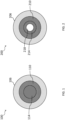
- FIG. 1 is a schematic of an example of an optical fiber 100.
- the optical fiber 100 comprises a second waveguide 106, an attenuating cladding 110, and a first waveguide 114.
- the second waveguide 106 is disposed around the attenuating cladding 110, which is disposed around the first waveguide 114.
- the second waveguide 106 is a waveguide cladding.
- the first waveguide 114 is a solid core.
- the second waveguide 106 is in direct contact with the attenuating cladding 110, which is in direct contact with the first waveguide 114.
- the first waveguide 114, the attenuating cladding 110, and the second waveguide 106 are concentrically arranged.
- FIG. 2 is a schematic of an example of an optical fiber 200.
- the optical fiber 200 comprises a second waveguide 206, an attenuating cladding 210, and a first waveguide 214.
- the second waveguide 206 is disposed around the attenuating cladding 210, which is disposed around the first waveguide 214.
- the second waveguide 206 is a waveguide cladding.
- the first waveguide 214 is a waveguide cladding.
- the second waveguide 206 is in direct contact with the attenuating cladding 210, which is in direct contact with the first waveguide 214.
- the space 218 shown inside of the first waveguide 214 may be filled by a solid cladding.
- the space 218 is filled with gas, such as air.
- FIG. 3 is a schematic of an example of an optical fiber 300.
- the optical fiber 300 comprises an outer coating 302, an outer cladding 304, a second waveguide 306, a second intermediate cladding 308, an attenuating cladding 310, a first intermediate cladding 312, and a first waveguide 214.
- the outer coating 302 is disposed around the outer cladding 304, which is disposed around the second waveguide 306, which is disposed around the second intermediate cladding 308, which is disposed around the attenuating cladding 310, which is disposed around the first intermediate cladding 312, which is disposed around the first waveguide 314.
- the second waveguide 306 is disposed around the attenuating cladding 310 and the attenuating cladding 310 is disposed around the first waveguide 314.
- the outer coating 302 is in direct contact with the outer cladding 304 is in direct contact with the second waveguide 306 is in direct contact with the second intermediate cladding 308 is in direct contact with the attenuating cladding 310 is in direct contact with the first intermediate cladding 312 is in direct contact with the first waveguide 314.
- the second waveguide 306 is a waveguide cladding.
- the first waveguide 314 is a solid core.
- the first intermediate cladding 312 and/or the second intermediate cladding 308 may be a photonic crystal layer having a photonic bandgap (e.g., a two-dimensional photonic crystal).
- FIG. 4 is a schematic of an example of an optical fiber 400.
- the optical fiber 400 comprises an outer coating 402, an outer cladding 404, a second waveguide 406, a second intermediate cladding 408, an attenuating cladding 410, a first intermediate cladding 412, and a first waveguide 414.
- the outer coating 402 is disposed around the outer cladding 404, which is disposed around the second waveguide 406, which is disposed around the second intermediate cladding 408, which is disposed around the attenuating cladding 410, which is disposed around the first intermediate cladding 412, which is disposed around the first waveguide 414.
- the second waveguide 406 is disposed around the attenuating cladding 410 and the attenuating cladding 410 is disposed around the first waveguide 414.
- the outer coating 402 is in direct contact with the outer cladding 404 is in direct contact with the second waveguide 406 is in direct contact with the second intermediate cladding 408 is in direct contact with the attenuating cladding 410 is in direct contact with the first intermediate cladding 412 is in direct contact with the first waveguide 414.
- the second waveguide 406 is a waveguide cladding.
- the first waveguide 414 is a hollow core.
- the first intermediate cladding 412 is a photonic crystal layer having a photonic bandgap (e.g., a two-dimensional photonic crystal).
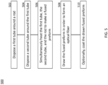
- FIG. 5 is a flow diagram of an example of a method 500 for forming an optical fiber.
- the method 500 is a rod-in-tube type process.
- the method 500 includes steps 502-508 and optional step 510.
- a first tube comprising attenuating-cladding material is disposed around a rod comprising solid-core material. Solid-core material may be the same or different from waveguide-material.
- a second tub comprising waveguide-cladding material is disposed around the first tube.
- the rod, the first tube, the second tube are simultaneously heated to make a fused preform.
- one or more additional tubes are disposed (e.g., between two tubes or between a rod and a two) prior to heating.
- the fused preform is drawn in order to form an optical fiber.
- a tube heated in step 506 may have an outer diameter of at least 50 mm, at least 100 mm, at least 150 mm, at least 200 mm, at least 300 mm, at least 500 mm, or at least 1 m (e.g., and less than 5 meters), that is drawn in order to form a fiber with substantially smaller diameter (e.g., at least ten times smaller, at least fifty times smaller, at least 100 times smaller, at least 500 times smaller, or at least 1000 times smaller diameter).
- the drawn fused preform is coated with an outer coating (e.g., comprising an opaque polymer).
- a method comprises disposing an attenuating tube comprising attenuating-cladding material around a first tube comprising first waveguide material.
- a second tube comprising second waveguide material may be disposed around the attenuating tube.
- the first tube, the second tube, and the attenuating tube may be simultaneously heated to make a fused preform.
- the fused preform may be drawn in order to form an optical fiber.
- the drawn fused preform may be coated with an outer coating (e.g., comprising an opaque polymer).
- FIG. 6 is a flow diagram of an example of a method 600 for using an optical fiber.
- the method 600 includes steps 602-606 and optional step 608.
- an optical fiber comprising a first waveguide (e.g., a core), an attenuating cladding disposed around the first waveguide, and a second waveguide (e.g., a waveguide cladding) disposed around the attenuating cladding is provided.
- a first signal is transmitted through the first waveguide.
- a second signal is transmitted through the second waveguide. The first signal and the second signal may be transmitted during a same period of time.
- a portion of the first signal and/or the second signal is completely attenuated by the attenuating cladding (e.g., thereby preventing it from entering another waveguide or cladding and/or re-entering its originating waveguide).
- a first portion of the first signal may propagate (e.g., leaks) from the first waveguide into the attenuating cladding and be completely attenuated by the attenuating cladding (e.g., such that the first portion cannot propagate from the attenuating cladding (e.g., into the waveguide cladding or the core)) (e.g., due to absorption of the first portion).
- a second portion of the second signal may propagate (e.g., leaks) from the second waveguide into the attenuating cladding and be completely attenuated by the attenuating cladding (e.g., such that the second portion cannot propagate from the attenuating cladding (e.g., into the waveguide cladding or the core)) (e.g., due to absorption of the second portion).
Landscapes
- Physics & Mathematics (AREA)
- Chemical & Material Sciences (AREA)
- Optics & Photonics (AREA)
- Engineering & Computer Science (AREA)
- General Physics & Mathematics (AREA)
- Organic Chemistry (AREA)
- Life Sciences & Earth Sciences (AREA)
- General Life Sciences & Earth Sciences (AREA)
- Geochemistry & Mineralogy (AREA)
- Manufacturing & Machinery (AREA)
- Materials Engineering (AREA)
- Crystallography & Structural Chemistry (AREA)
- Endoscopes (AREA)
- Optical Fibers, Optical Fiber Cores, And Optical Fiber Bundles (AREA)
- Investigating Or Analysing Materials By Optical Means (AREA)
- Light Guides In General And Applications Therefor (AREA)
- Optical Modulation, Optical Deflection, Nonlinear Optics, Optical Demodulation, Optical Logic Elements (AREA)
Claims (16)
- Système comprenant une fibre optique (100, 200, 300, 400) et une jonction rotative, la fibre optique étant en communication optique avec la jonction rotative,la fibre optique comprenant un premier guide d'ondes (114, 214, 314, 414) et un second guide d'ondes (106, 206, 306, 406),caractérisé en ce quela fibre optique comprend en outre une gaine d'atténuation (110, 210, 310, 410) disposée autour du premier guide d'ondes, et le second guide d'ondes est disposé autour de la gaine d'atténuation.
- Système selon la revendication 1, la gaine d'atténuation comprenant un dopant, éventuellement la gaine d'atténuation comprenant un verre et le dopant étant dispersé dans le verre.
- Système selon la revendication 2, le dopant comprenant l'un des éléments suivants :a) un métal, par exemple le dopant comprenant un oxyde métallique ou un chlorure métallique, ou le dopant étant un métal pur ;b) du bore ; ouc) un ou plusieurs diffuseurs de Rayleigh.
- Système selon l'une quelconque des revendications précédentes, la gaine d'atténuation étant opaque.
- Système selon l'une quelconque des revendications précédentes, avec une ou plusieurs des conditions suivantes :
a) une longueur d'atténuation de la gaine d'atténuation ne dépasse pas 1 mètre, de préférence entre 5 mm et 35 mm, plus préférablement environ 20 mm ; ou b) la gaine d'atténuation est construite, dimensionnée et façonnée pour atténuer au moins 90 % de la lumière dans une distance qui est au moins 3 mm et pas plus de 1 m, de préférence entre 5 mm et 35 mm, plus préférablement environ 20 mm. - Système selon l'une quelconque des revendications précédentes, une partie imaginaire d'un indice de réfraction de la gaine d'atténuation étant supérieure à une partie imaginaire d'un indice de réfraction du premier guide d'ondes et à une partie imaginaire d'un indice de réfraction du second guide d'ondes.
- Système selon l'une quelconque des revendications précédentes, le premier guide d'ondes étant construit, dimensionné et façonné pour confiner sensiblement la lumière d'une première longueur d'onde et le second guide d'ondes étant construit, dimensionné et façonné pour confiner sensiblement la lumière d'une seconde longueur d'onde.
- Système selon l'une quelconque des revendications précédentes, le premier guide d'ondes étant une âme pleine, ou le premier guide d'ondes étant une âme creuse.
- Système selon l'une quelconque des revendications précédentes, la fibre optique comprenant une première gaine intermédiaire (312, 412) disposée autour du premier guide d'ondes, la première gaine intermédiaire étant disposée entre le premier guide d'ondes et la gaine d'atténuation, de préférence la gaine d'atténuation étant en contact direct avec la première gaine intermédiaire et la première gaine intermédiaire étant en contact direct avec le premier guide d'ondes ; et/ou
la fibre optique comprenant une seconde gaine intermédiaire (308, 408) disposée autour de la gaine d'atténuation et entre le second guide d'ondes et la gaine d'atténuation, de préférence le second guide d'ondes étant en contact direct avec la seconde gaine intermédiaire. - Système selon la revendication 9, la gaine d'atténuation ayant un indice de réfraction qui est supérieur à un indice de réfraction de la première gaine intermédiaire et à un indice de réfraction de la seconde gaine intermédiaire, et/ou la première gaine intermédiaire, la seconde gaine intermédiaire, ou la première gaine intermédiaire et la seconde gaine intermédiaire étant une couche de cristal photonique ayant une bande interdite photonique, la couche étant un cristal photonique bidimensionnel.
- Système selon l'une quelconque des revendications précédentes, comprenant une gaine extérieure disposée autour du second guide d'ondes, de préférence la gaine extérieure étant en contact direct avec le second guide d'ondes.
- Système selon n'importe quelle revendication précédente, comprenant en outre une sonde, la sonde étant en communication optique avec la jonction rotative, et la sonde étant physiquement connectée à la jonction rotative.
- Système selon n'importe quelle revendication précédente, comprenant un module d'imagerie pour l'imagerie OCT, et un module de spectroscopie pour la spectroscopie dans le proche infrarouge, de préférence le module d'imagerie comprenant l'une d'une première source de lumière et d'une seconde source de lumière et le module de spectroscopie comprenant une source de lumière différente de la première source de lumière et de la seconde source de lumière.
- Cathéter cardiaque, comprenant le système selon l'une quelconque des revendications 1 à 13, une première source de lumière, et une seconde source de lumière, la première source de lumière étant en communication optique avec le premier guide d'ondes, et la seconde source de lumière étant en communication optique avec le second guide d'ondes.
- Procédé d'utilisation d'une fibre optique comprenant :la fourniture d'un système selon l'une quelconque des revendications 1 à 13 ou d'un cathéter selon la revendication 14 (602) ;la transmission d'un premier signal à travers le premier guide d'ondes (604) ; etla transmission d'un second signal à travers le second guide d'ondes (606), de préférence le premier signal et le second signal étant transmis au cours d'une même période de temps.
- Procédé selon la revendication 15, comprenant l'atténuation complète d'une première partie du premier signal avec la gaine d'atténuation (608).
Applications Claiming Priority (2)
| Application Number | Priority Date | Filing Date | Title |
|---|---|---|---|
| US201862757152P | 2018-11-07 | 2018-11-07 | |
| PCT/US2019/060158 WO2020097267A1 (fr) | 2018-11-07 | 2019-11-06 | Fibres optiques, leurs procédés de formation, et leurs procédés d'utilisation |
Publications (2)
| Publication Number | Publication Date |
|---|---|
| EP3877793A1 EP3877793A1 (fr) | 2021-09-15 |
| EP3877793B1 true EP3877793B1 (fr) | 2025-02-12 |
Family
ID=69160037
Family Applications (1)
| Application Number | Title | Priority Date | Filing Date |
|---|---|---|---|
| EP19835998.6A Active EP3877793B1 (fr) | 2018-11-07 | 2019-11-06 | Systeme comprenant une fibre optique et son procédé d'utilisation |
Country Status (4)
| Country | Link |
|---|---|
| US (1) | US11867943B2 (fr) |
| EP (1) | EP3877793B1 (fr) |
| JP (1) | JP7555917B2 (fr) |
| WO (1) | WO2020097267A1 (fr) |
Families Citing this family (4)
| Publication number | Priority date | Publication date | Assignee | Title |
|---|---|---|---|---|
| WO2020097267A1 (fr) | 2018-11-07 | 2020-05-14 | Spectrawave, Inc. | Fibres optiques, leurs procédés de formation, et leurs procédés d'utilisation |
| WO2021033465A1 (fr) * | 2019-08-20 | 2021-02-25 | 株式会社カネカ | Appareil d'irradiation de lumière médicale |
| US12195380B2 (en) * | 2021-03-31 | 2025-01-14 | Sterlite Technologies Limited | Preform assembly for drawing multicore or holey optical fibre and method of manufacturing thereof |
| WO2026028440A1 (fr) * | 2024-08-02 | 2026-02-05 | 株式会社フジクラ | Fibre multicoeur |
Family Cites Families (14)
| Publication number | Priority date | Publication date | Assignee | Title |
|---|---|---|---|---|
| US5815627A (en) | 1994-01-13 | 1998-09-29 | Rutgers, The State University Of New Jersey | Co-axial hollow core waveguide |
| JP2004521378A (ja) | 2001-01-25 | 2004-07-15 | オムニガイド コミュニケーションズ インコーポレイテッド | 大きいコア半径を有する低損失フォトニック結晶導波路 |
| US6636675B2 (en) | 2001-03-12 | 2003-10-21 | Verrillon, Inc. | Optical fiber with reduced cladding-mode loss |
| JP2004333909A (ja) | 2003-05-08 | 2004-11-25 | Showa Electric Wire & Cable Co Ltd | クラッドモード減衰性光導波路及びそれを用いた光素子 |
| US7526167B1 (en) * | 2005-06-24 | 2009-04-28 | Lockheed Martin Corporation | Apparatus and method for a high-gain double-clad amplifier |
| US7835608B2 (en) | 2006-03-21 | 2010-11-16 | Lockheed Martin Corporation | Method and apparatus for optical delivery fiber having cladding with absorbing regions |
| JP2010102276A (ja) | 2008-09-26 | 2010-05-06 | Mitsubishi Cable Ind Ltd | 光ファイバ及びその製造方法 |
| JPWO2013027776A1 (ja) * | 2011-08-25 | 2015-03-19 | 国立大学法人横浜国立大学 | マルチコアファイバおよびマルチコアファイバのコアの配置方法 |
| WO2017049085A1 (fr) | 2015-09-16 | 2017-03-23 | The General Hospital Corporation | Appareil et procédés pour dispositif d'imagerie à tunnel miroir et pour fournir des faisceaux à pseudo-fonction de bessel dans un système optique miniaturisé pour imagerie |
| KR101787874B1 (ko) | 2016-02-29 | 2017-10-20 | 한양대학교 산학협력단 | 잡음 감쇠 시준기 및 이를 포함하는 영상 카테터 시스템 |
| WO2018022413A1 (fr) | 2016-07-29 | 2018-02-01 | Corning Incorporated | Fibre optique monomode à noyau dopée au chlore et à faible perte de courbure |
| US11224336B2 (en) * | 2017-11-17 | 2022-01-18 | Canon U.S.A., Inc. | Rotational extender and/or repeater for rotating fiber based optical imaging systems, and methods and storage mediums for use therewith |
| WO2020097267A1 (fr) | 2018-11-07 | 2020-05-14 | Spectrawave, Inc. | Fibres optiques, leurs procédés de formation, et leurs procédés d'utilisation |
| US11213213B2 (en) * | 2019-03-26 | 2022-01-04 | Kotl, Llc | Systems and methods of combined optical coherence tomography and pressure measurement |
-
2019
- 2019-11-06 WO PCT/US2019/060158 patent/WO2020097267A1/fr not_active Ceased
- 2019-11-06 EP EP19835998.6A patent/EP3877793B1/fr active Active
- 2019-11-06 JP JP2021525015A patent/JP7555917B2/ja active Active
- 2019-11-06 US US17/291,921 patent/US11867943B2/en active Active
Also Published As
| Publication number | Publication date |
|---|---|
| JP2022506903A (ja) | 2022-01-17 |
| US11867943B2 (en) | 2024-01-09 |
| US20220011506A1 (en) | 2022-01-13 |
| JP7555917B2 (ja) | 2024-09-25 |
| EP3877793A1 (fr) | 2021-09-15 |
| WO2020097267A1 (fr) | 2020-05-14 |
Similar Documents
| Publication | Publication Date | Title |
|---|---|---|
| EP3877793B1 (fr) | Systeme comprenant une fibre optique et son procédé d'utilisation | |
| EP2541292B1 (fr) | Fibre optique multimode | |
| US10094974B2 (en) | Multicore optical fiber with a randomized core structure | |
| JP5242582B2 (ja) | フォトニックバンドギャップファイバ | |
| Wang et al. | Optical probe based on double-clad optical fiber for fluorescence spectroscopy | |
| US20140212083A1 (en) | Optical fiber for coherent anti-stokes raman scattering endoscopes | |
| JPWO2017217539A1 (ja) | 結合型マルチコア光ファイバの軸合わせ方法 | |
| US9448359B2 (en) | Single mode propagation in microstructured optical fibers | |
| US11314015B2 (en) | Multi-core optical fiber | |
| JP2022506903A5 (fr) | ||
| Kobayashi et al. | Multi-element hollow-core anti-resonant fiber for infrared thermal imaging | |
| US10502897B2 (en) | Device for selectively increasing higher-order mode losses in an optical fiber | |
| JP2010102276A (ja) | 光ファイバ及びその製造方法 | |
| RU2413257C2 (ru) | Одномодовый двухслойный кристаллический инфракрасный световод | |
| JP5597005B2 (ja) | 光ファイバ型光学フィルタ | |
| Rabii et al. | Optical properties of dual-core hollow waveguides | |
| Korsakov et al. | Microstructured single-mode IR fibers based on metal halides with increased mode-field diameter | |
| US20250172746A1 (en) | Uncoupled multicore optical fiber | |
| Xing et al. | A novel mode-division (de) multiplexer with degenerate modes output for MIMO-FREE applications | |
| US20250172747A1 (en) | Uncoupled multicore optical fiber with alkali doped cores | |
| Choi et al. | Microlensed dual-fiber probe for depth-resolved fluorescence measurements | |
| Tesfa | CE-DOPED FIBER AS A GAIN MATERIAL FOR VISIBLE LASER SOURCES | |
| Suzuki et al. | Numerical analysis of optical confinement in silica and tellurite multicore fibers for near-infrared image transportation | |
| Yang et al. | Long-wave infrared chalcogenide fiber bundle for thermal image transmission | |
| Geete et al. | Simulation of Heterogeneous FM-MCF for the Enhancement of Capacity using Hexagonal, Octagonal and Decagonal Structures: A Review |
Legal Events
| Date | Code | Title | Description |
|---|---|---|---|
| STAA | Information on the status of an ep patent application or granted ep patent |
Free format text: STATUS: UNKNOWN |
|
| STAA | Information on the status of an ep patent application or granted ep patent |
Free format text: STATUS: THE INTERNATIONAL PUBLICATION HAS BEEN MADE |
|
| PUAI | Public reference made under article 153(3) epc to a published international application that has entered the european phase |
Free format text: ORIGINAL CODE: 0009012 |
|
| STAA | Information on the status of an ep patent application or granted ep patent |
Free format text: STATUS: REQUEST FOR EXAMINATION WAS MADE |
|
| 17P | Request for examination filed |
Effective date: 20210507 |
|
| AK | Designated contracting states |
Kind code of ref document: A1 Designated state(s): AL AT BE BG CH CY CZ DE DK EE ES FI FR GB GR HR HU IE IS IT LI LT LU LV MC MK MT NL NO PL PT RO RS SE SI SK SM TR |
|
| DAV | Request for validation of the european patent (deleted) | ||
| DAX | Request for extension of the european patent (deleted) | ||
| STAA | Information on the status of an ep patent application or granted ep patent |
Free format text: STATUS: EXAMINATION IS IN PROGRESS |
|
| 17Q | First examination report despatched |
Effective date: 20221012 |
|
| RAP3 | Party data changed (applicant data changed or rights of an application transferred) |
Owner name: SPECTRAWAVE, INC. |
|
| GRAP | Despatch of communication of intention to grant a patent |
Free format text: ORIGINAL CODE: EPIDOSNIGR1 |
|
| STAA | Information on the status of an ep patent application or granted ep patent |
Free format text: STATUS: GRANT OF PATENT IS INTENDED |
|
| RIC1 | Information provided on ipc code assigned before grant |
Ipc: C03B 37/027 20060101ALN20240822BHEP Ipc: G02B 6/02 20060101ALI20240822BHEP Ipc: C03B 37/012 20060101ALI20240822BHEP Ipc: A61B 5/00 20060101ALI20240822BHEP Ipc: G02B 6/036 20060101AFI20240822BHEP |
|
| INTG | Intention to grant announced |
Effective date: 20240902 |
|
| RIC1 | Information provided on ipc code assigned before grant |
Ipc: C03B 37/027 20060101ALN20240823BHEP Ipc: G02B 6/02 20060101ALI20240823BHEP Ipc: C03B 37/012 20060101ALI20240823BHEP Ipc: A61B 5/00 20060101ALI20240823BHEP Ipc: G02B 6/036 20060101AFI20240823BHEP |
|
| GRAS | Grant fee paid |
Free format text: ORIGINAL CODE: EPIDOSNIGR3 |
|
| GRAA | (expected) grant |
Free format text: ORIGINAL CODE: 0009210 |
|
| STAA | Information on the status of an ep patent application or granted ep patent |
Free format text: STATUS: THE PATENT HAS BEEN GRANTED |
|
| AK | Designated contracting states |
Kind code of ref document: B1 Designated state(s): AL AT BE BG CH CY CZ DE DK EE ES FI FR GB GR HR HU IE IS IT LI LT LU LV MC MK MT NL NO PL PT RO RS SE SI SK SM TR |
|
| REG | Reference to a national code |
Ref country code: GB Ref legal event code: FG4D |
|
| REG | Reference to a national code |
Ref country code: CH Ref legal event code: EP |
|
| REG | Reference to a national code |
Ref country code: DE Ref legal event code: R096 Ref document number: 602019065889 Country of ref document: DE |
|
| REG | Reference to a national code |
Ref country code: IE Ref legal event code: FG4D |
|
| REG | Reference to a national code |
Ref country code: NL Ref legal event code: MP Effective date: 20250212 |
|
| PG25 | Lapsed in a contracting state [announced via postgrant information from national office to epo] |
Ref country code: RS Free format text: LAPSE BECAUSE OF FAILURE TO SUBMIT A TRANSLATION OF THE DESCRIPTION OR TO PAY THE FEE WITHIN THE PRESCRIBED TIME-LIMIT Effective date: 20250512 |
|
| PG25 | Lapsed in a contracting state [announced via postgrant information from national office to epo] |
Ref country code: FI Free format text: LAPSE BECAUSE OF FAILURE TO SUBMIT A TRANSLATION OF THE DESCRIPTION OR TO PAY THE FEE WITHIN THE PRESCRIBED TIME-LIMIT Effective date: 20250212 |
|
| PG25 | Lapsed in a contracting state [announced via postgrant information from national office to epo] |
Ref country code: PL Free format text: LAPSE BECAUSE OF FAILURE TO SUBMIT A TRANSLATION OF THE DESCRIPTION OR TO PAY THE FEE WITHIN THE PRESCRIBED TIME-LIMIT Effective date: 20250212 |
|
| PG25 | Lapsed in a contracting state [announced via postgrant information from national office to epo] |
Ref country code: ES Free format text: LAPSE BECAUSE OF FAILURE TO SUBMIT A TRANSLATION OF THE DESCRIPTION OR TO PAY THE FEE WITHIN THE PRESCRIBED TIME-LIMIT Effective date: 20250212 |
|
| REG | Reference to a national code |
Ref country code: LT Ref legal event code: MG9D |
|
| PG25 | Lapsed in a contracting state [announced via postgrant information from national office to epo] |
Ref country code: NO Free format text: LAPSE BECAUSE OF FAILURE TO SUBMIT A TRANSLATION OF THE DESCRIPTION OR TO PAY THE FEE WITHIN THE PRESCRIBED TIME-LIMIT Effective date: 20250512 Ref country code: IS Free format text: LAPSE BECAUSE OF FAILURE TO SUBMIT A TRANSLATION OF THE DESCRIPTION OR TO PAY THE FEE WITHIN THE PRESCRIBED TIME-LIMIT Effective date: 20250612 |
|
| PG25 | Lapsed in a contracting state [announced via postgrant information from national office to epo] |
Ref country code: NL Free format text: LAPSE BECAUSE OF FAILURE TO SUBMIT A TRANSLATION OF THE DESCRIPTION OR TO PAY THE FEE WITHIN THE PRESCRIBED TIME-LIMIT Effective date: 20250212 |
|
| PG25 | Lapsed in a contracting state [announced via postgrant information from national office to epo] |
Ref country code: HR Free format text: LAPSE BECAUSE OF FAILURE TO SUBMIT A TRANSLATION OF THE DESCRIPTION OR TO PAY THE FEE WITHIN THE PRESCRIBED TIME-LIMIT Effective date: 20250212 |
|
| PG25 | Lapsed in a contracting state [announced via postgrant information from national office to epo] |
Ref country code: PT Free format text: LAPSE BECAUSE OF FAILURE TO SUBMIT A TRANSLATION OF THE DESCRIPTION OR TO PAY THE FEE WITHIN THE PRESCRIBED TIME-LIMIT Effective date: 20250612 Ref country code: LV Free format text: LAPSE BECAUSE OF FAILURE TO SUBMIT A TRANSLATION OF THE DESCRIPTION OR TO PAY THE FEE WITHIN THE PRESCRIBED TIME-LIMIT Effective date: 20250212 |
|
| PG25 | Lapsed in a contracting state [announced via postgrant information from national office to epo] |
Ref country code: BG Free format text: LAPSE BECAUSE OF FAILURE TO SUBMIT A TRANSLATION OF THE DESCRIPTION OR TO PAY THE FEE WITHIN THE PRESCRIBED TIME-LIMIT Effective date: 20250212 Ref country code: GR Free format text: LAPSE BECAUSE OF FAILURE TO SUBMIT A TRANSLATION OF THE DESCRIPTION OR TO PAY THE FEE WITHIN THE PRESCRIBED TIME-LIMIT Effective date: 20250513 |
|
| REG | Reference to a national code |
Ref country code: AT Ref legal event code: MK05 Ref document number: 1766558 Country of ref document: AT Kind code of ref document: T Effective date: 20250212 |
|
| PG25 | Lapsed in a contracting state [announced via postgrant information from national office to epo] |
Ref country code: SE Free format text: LAPSE BECAUSE OF FAILURE TO SUBMIT A TRANSLATION OF THE DESCRIPTION OR TO PAY THE FEE WITHIN THE PRESCRIBED TIME-LIMIT Effective date: 20250212 |
|
| PG25 | Lapsed in a contracting state [announced via postgrant information from national office to epo] |
Ref country code: SM Free format text: LAPSE BECAUSE OF FAILURE TO SUBMIT A TRANSLATION OF THE DESCRIPTION OR TO PAY THE FEE WITHIN THE PRESCRIBED TIME-LIMIT Effective date: 20250212 |
|
| PG25 | Lapsed in a contracting state [announced via postgrant information from national office to epo] |
Ref country code: DK Free format text: LAPSE BECAUSE OF FAILURE TO SUBMIT A TRANSLATION OF THE DESCRIPTION OR TO PAY THE FEE WITHIN THE PRESCRIBED TIME-LIMIT Effective date: 20250212 |
|
| PG25 | Lapsed in a contracting state [announced via postgrant information from national office to epo] |
Ref country code: AT Free format text: LAPSE BECAUSE OF FAILURE TO SUBMIT A TRANSLATION OF THE DESCRIPTION OR TO PAY THE FEE WITHIN THE PRESCRIBED TIME-LIMIT Effective date: 20250212 |
|
| PG25 | Lapsed in a contracting state [announced via postgrant information from national office to epo] |
Ref country code: EE Free format text: LAPSE BECAUSE OF FAILURE TO SUBMIT A TRANSLATION OF THE DESCRIPTION OR TO PAY THE FEE WITHIN THE PRESCRIBED TIME-LIMIT Effective date: 20250212 Ref country code: CZ Free format text: LAPSE BECAUSE OF FAILURE TO SUBMIT A TRANSLATION OF THE DESCRIPTION OR TO PAY THE FEE WITHIN THE PRESCRIBED TIME-LIMIT Effective date: 20250212 |
|
| PG25 | Lapsed in a contracting state [announced via postgrant information from national office to epo] |
Ref country code: RO Free format text: LAPSE BECAUSE OF FAILURE TO SUBMIT A TRANSLATION OF THE DESCRIPTION OR TO PAY THE FEE WITHIN THE PRESCRIBED TIME-LIMIT Effective date: 20250212 |
|
| PG25 | Lapsed in a contracting state [announced via postgrant information from national office to epo] |
Ref country code: SK Free format text: LAPSE BECAUSE OF FAILURE TO SUBMIT A TRANSLATION OF THE DESCRIPTION OR TO PAY THE FEE WITHIN THE PRESCRIBED TIME-LIMIT Effective date: 20250212 |
|
| REG | Reference to a national code |
Ref country code: DE Ref legal event code: R097 Ref document number: 602019065889 Country of ref document: DE |
|
| PLBE | No opposition filed within time limit |
Free format text: ORIGINAL CODE: 0009261 |
|
| STAA | Information on the status of an ep patent application or granted ep patent |
Free format text: STATUS: NO OPPOSITION FILED WITHIN TIME LIMIT |
|
| PGFP | Annual fee paid to national office [announced via postgrant information from national office to epo] |
Ref country code: DE Payment date: 20251119 Year of fee payment: 7 |
|
| PGFP | Annual fee paid to national office [announced via postgrant information from national office to epo] |
Ref country code: GB Payment date: 20251121 Year of fee payment: 7 |
|
| PGFP | Annual fee paid to national office [announced via postgrant information from national office to epo] |
Ref country code: IT Payment date: 20251125 Year of fee payment: 7 |
|
| PGFP | Annual fee paid to national office [announced via postgrant information from national office to epo] |
Ref country code: FR Payment date: 20251126 Year of fee payment: 7 |
|
| 26N | No opposition filed |
Effective date: 20251113 |
|
| REG | Reference to a national code |
Ref country code: DE Ref legal event code: R081 Ref document number: 602019065889 Country of ref document: DE Owner name: KONINKLIJKE PHILIPS N.V., NL Free format text: FORMER OWNER: SPECTRAWAVE, INC., BEDFORD, MA, US Ref country code: DE Ref legal event code: R082 Ref document number: 602019065889 Country of ref document: DE |