EP3877963B1 - Appareil de commande portatif pour commander un capteur de mouvement - Google Patents
Appareil de commande portatif pour commander un capteur de mouvement Download PDFInfo
- Publication number
- EP3877963B1 EP3877963B1 EP20776103.2A EP20776103A EP3877963B1 EP 3877963 B1 EP3877963 B1 EP 3877963B1 EP 20776103 A EP20776103 A EP 20776103A EP 3877963 B1 EP3877963 B1 EP 3877963B1
- Authority
- EP
- European Patent Office
- Prior art keywords
- motion sensor
- control device
- detection
- motion
- detection threshold
- Prior art date
- Legal status (The legal status is an assumption and is not a legal conclusion. Google has not performed a legal analysis and makes no representation as to the accuracy of the status listed.)
- Active
Links
Images


Classifications
-
- H—ELECTRICITY
- H04—ELECTRIC COMMUNICATION TECHNIQUE
- H04M—TELEPHONIC COMMUNICATION
- H04M1/00—Substation equipment, e.g. for use by subscribers
- H04M1/72—Mobile telephones; Cordless telephones, i.e. devices for establishing wireless links to base stations without route selection
- H04M1/724—User interfaces specially adapted for cordless or mobile telephones
- H04M1/72403—User interfaces specially adapted for cordless or mobile telephones with means for local support of applications that increase the functionality
- H04M1/72409—User interfaces specially adapted for cordless or mobile telephones with means for local support of applications that increase the functionality by interfacing with external accessories
- H04M1/72415—User interfaces specially adapted for cordless or mobile telephones with means for local support of applications that increase the functionality by interfacing with external accessories for remote control of appliances
-
- G—PHYSICS
- G08—SIGNALLING
- G08C—TRANSMISSION SYSTEMS FOR MEASURED VALUES, CONTROL OR SIMILAR SIGNALS
- G08C17/00—Arrangements for transmitting signals characterised by the use of a wireless electrical link
- G08C17/02—Arrangements for transmitting signals characterised by the use of a wireless electrical link using a radio link
-
- H—ELECTRICITY
- H04—ELECTRIC COMMUNICATION TECHNIQUE
- H04M—TELEPHONIC COMMUNICATION
- H04M1/00—Substation equipment, e.g. for use by subscribers
- H04M1/72—Mobile telephones; Cordless telephones, i.e. devices for establishing wireless links to base stations without route selection
- H04M1/724—User interfaces specially adapted for cordless or mobile telephones
- H04M1/72403—User interfaces specially adapted for cordless or mobile telephones with means for local support of applications that increase the functionality
- H04M1/72409—User interfaces specially adapted for cordless or mobile telephones with means for local support of applications that increase the functionality by interfacing with external accessories
- H04M1/72412—User interfaces specially adapted for cordless or mobile telephones with means for local support of applications that increase the functionality by interfacing with external accessories using two-way short-range wireless interfaces
-
- G—PHYSICS
- G01—MEASURING; TESTING
- G01S—RADIO DIRECTION-FINDING; RADIO NAVIGATION; DETERMINING DISTANCE OR VELOCITY BY USE OF RADIO WAVES; LOCATING OR PRESENCE-DETECTING BY USE OF THE REFLECTION OR RERADIATION OF RADIO WAVES; ANALOGOUS ARRANGEMENTS USING OTHER WAVES
- G01S13/00—Systems using the reflection or reradiation of radio waves, e.g. radar systems; Analogous systems using reflection or reradiation of waves whose nature or wavelength is irrelevant or unspecified
- G01S13/02—Systems using reflection of radio waves, e.g. primary radar systems; Analogous systems
- G01S13/50—Systems of measurement based on relative movement of target
- G01S13/58—Velocity or trajectory determination systems; Sense-of-movement determination systems
-
- G—PHYSICS
- G06—COMPUTING OR CALCULATING; COUNTING
- G06F—ELECTRIC DIGITAL DATA PROCESSING
- G06F3/00—Input arrangements for transferring data to be processed into a form capable of being handled by the computer; Output arrangements for transferring data from processing unit to output unit, e.g. interface arrangements
- G06F3/01—Input arrangements or combined input and output arrangements for interaction between user and computer
- G06F3/048—Interaction techniques based on graphical user interfaces [GUI]
- G06F3/0487—Interaction techniques based on graphical user interfaces [GUI] using specific features provided by the input device, e.g. functions controlled by the rotation of a mouse with dual sensing arrangements, or of the nature of the input device, e.g. tap gestures based on pressure sensed by a digitiser
- G06F3/0488—Interaction techniques based on graphical user interfaces [GUI] using specific features provided by the input device, e.g. functions controlled by the rotation of a mouse with dual sensing arrangements, or of the nature of the input device, e.g. tap gestures based on pressure sensed by a digitiser using a touch-screen or digitiser, e.g. input of commands through traced gestures
-
- H—ELECTRICITY
- H04—ELECTRIC COMMUNICATION TECHNIQUE
- H04Q—SELECTING
- H04Q9/00—Arrangements in telecontrol or telemetry systems for selectively calling a substation from a main station, in which substation desired apparatus is selected for applying a control signal thereto or for obtaining measured values therefrom
-
- H—ELECTRICITY
- H04—ELECTRIC COMMUNICATION TECHNIQUE
- H04W—WIRELESS COMMUNICATION NETWORKS
- H04W4/00—Services specially adapted for wireless communication networks; Facilities therefor
- H04W4/30—Services specially adapted for particular environments, situations or purposes
- H04W4/38—Services specially adapted for particular environments, situations or purposes for collecting sensor information
-
- G—PHYSICS
- G08—SIGNALLING
- G08C—TRANSMISSION SYSTEMS FOR MEASURED VALUES, CONTROL OR SIMILAR SIGNALS
- G08C2201/00—Transmission systems of control signals via wireless link
- G08C2201/90—Additional features
- G08C2201/93—Remote control using other portable devices, e.g. mobile phone, PDA, laptop
-
- H—ELECTRICITY
- H04—ELECTRIC COMMUNICATION TECHNIQUE
- H04M—TELEPHONIC COMMUNICATION
- H04M2250/00—Details of telephonic subscriber devices
- H04M2250/12—Details of telephonic subscriber devices including a sensor for measuring a physical value, e.g. temperature or motion
Definitions
- the present invention relates to portable control devices for controlling motion detectors and methods for controlling motion detectors by means of portable control devices.
- Movements can be detected using infrared radiation, radar waves, ultrasound, or even camera images, among others.
- To prevent unwanted motion detection it is always necessary to adjust the motion sensors.
- the adjustability of the motion detection range i.e., the maximum distance up to which movement should be detected—is of interest, but is usually difficult to implement.
- a radar sensor does not have a fixed range. Distinguishing between motion detection in the immediate vicinity and non-motion detection at a greater distance is achieved by setting a threshold for the intensity of the received, backscattered radar waves detected by the sensor. A low threshold corresponds to the ability to detect movements even at greater distances, while a high threshold limits motion detection to the sensor's immediate vicinity.
- the printed matter US 2017/245347 A1 describes a motion sensor that can communicate wirelessly with a user device so that sensor settings can be adjusted via an application running on the user device.
- the GB 2 524 029 A discloses a system for testing a presence detector.
- a sensor unit is attached to a surface of a building.
- the sensor unit comprises a sensor element for detecting a presence.
- a remote device is arranged to communicate with the sensor unit via wireless signals.
- the remote device comprises a display 121.
- the sensor unit is arranged to operate in a test mode in which, in response to the detection of a presence by the sensor element of the sensor unit, sends a detection signal to the remote device.
- the remote device is configured to activate the indicator to indicate presence detection in response to receiving a detection signal from the sensor unit.
- a portable control device for controlling a motion sensor comprises communication means, display means and input means.
- the communication means are used for wireless communication with a motion sensor and are suitable for receiving a detection signal currently generated in the motion sensor from the motion sensor while the control device is located within a detection range of the motion sensor.
- the display means are used to display this detection signal.
- the input means are used to set a detection threshold at which movement is detected by the motion sensor, based on the displayed detection signal. The set detection threshold is transmitted to the motion sensor via the communication means and set there as the valid detection threshold.
- a portable control device is used to adjust the detection threshold, which allows the detection threshold to be changed within the detection range of the motion sensor.
- the control device is equipped with communication means, such as a radio antenna or a Bluetooth interface. equipped. While an operator of the control device moves within the detection range of the motion sensor, the motion sensor generates a detection signal corresponding to the movement and communicates it to the control device via the communication means.
- the detection signal is then displayed on the control device's display means, which may be a screen.
- the detection signal may be stored in a memory of the control device.
- Communication and display means allow an operator of the control device to view the signal actually detected by the motion detector while performing the movements that generate the signal. This enables the operator to immediately understand how their current movements affect the motion detection. It is therefore not necessary to determine this by setting thresholds on the motion detector and then checking the settings in the detection area. Rather, a single glance at the display means of the control device is sufficient to understand the effects of the currently performed movements on the motion detector.
- the detection threshold can then be easily entered directly into the control device using the input means and transmitted to the motion detector.
- the detection threshold can be set to the value of the detection signal caused by the current movement. Since a movement closer to the sensor typically generates a stronger detection signal than a movement further away from the sensor, this corresponds to setting the detection threshold to a sensor range corresponding to the operator's position.
- the display and input devices can be combined to form a touchscreen.
- the control device can be implemented, for example, using a smartphone or tablet, on which the programs or applications (apps) necessary for the functionalities described above are stored or executed.
- smartphone or tablet on which the programs or applications (apps) necessary for the functionalities described above are stored or executed.
- smartphone or tablet on which the programs or applications (apps) necessary for the functionalities described above are stored or executed.
- any smartphone or similar device to be used as a control device, provided it has a communication interface with the motion sensors, e.g., via Bluetooth, Wi-Fi, or NFC. This eliminates the need for additional control devices.
- the input means can also be provided separately from the display means.
- input can also be made via rotary knobs, sliders, or a keyboard attached to or connected to the control device, as with a laptop.
- This can be advantageous if special functions are to be implemented that cannot be realized with a smartphone or the like, such as increased impact resistance.
- the display means not as a screen, but rather, for example, in the form of several illuminated displays that, for example, use five different lights to indicate five levels of detection signal strength.
- the threshold value could then also be set accordingly to five levels, e.g., by operating push buttons, rotary heads, or sliders.
- the signal exchange between the motion sensor and the control device can also be largely automatic.
- the only necessary input at the control device is to start the range adjustment.
- the motion sensor measures the detection signal and automatically sets the detection threshold to the measured detection signal.
- the detection signal is then "displayed" at the control device only to the extent that it is recognizable from the control device that an adjustment of the detection threshold has been started or is being carried out.
- the range of the motion sensor can also be easily adjusted in this way.
- the display means may be suitable for displaying the set detection threshold in addition to the detection signal. This provides a particularly intuitive and, due to its ease of use, time-saving adjustment of the range.
- the display means are suitable for displaying an intensity of the detection signal currently generated in the motion detector, and the input means may be suitable for setting the detection threshold to an intensity value.
- the motion sensor sends the intensity of the received detection signal to the control device.
- this can be the detected intensity of the radar waves emitted by the sensor and backscattered by a moving object, or quantities derived from them, such as a Doppler signal.
- An IR sensor can measure the intensity of the infrared radiation emitted by an object.
- the displayed intensity can be used for any type of sensor that operates based on measurements of radiation or waves reflected or emitted by a moving object.
- ultrasonic sensors or similar sensors can also be used.
- the intensity of the signal measured by the motion sensor can be easily compared to a detection threshold. If the intensity is higher than a threshold set based on movement at a specific distance, it can be assumed that the corresponding movement occurs at a distance from the sensor that is smaller than the specified distance. An operator can therefore easily adjust the range based on the intensity. Since the signal generated by adults typically depends only slightly on their specific body shape for common sensor types (radar, IR, ultrasonic sensors, and the like), it is thus possible to reliably adjust the range. This range is, to a first approximation, correct not only for the specific (adult) operator of the control device, but for all adults.
- the intensity is displayed on a scale between a minimum intensity and a maximum intensity, and the intensity threshold can be set on the same scale.
- a scale is provided as visual feedback, indicating the intensity of a movement currently performed by an operator of the control device.
- the operator can easily enter the detection threshold on this scale, e.g., using a touchscreen directly on the scale, using a keyboard, or using push or rotary knobs. This enables precise setting of the detection threshold and thus precise range adjustment.
- an experienced operator can use the intensity displayed on the scale for a specific distance to determine the intensity at other distances and set the detection threshold to this intensity estimated from the scale. This allows for even more flexible and thus time-saving adjustment of the range of motion sensors.
- the display means may be suitable for displaying further operating parameters of the motion sensor or of an electrical device controlled by the motion sensor
- the input means may be suitable for receiving settings of the further operating parameters
- the communication means may be suitable for transmitting the received settings of the further operating parameters to the motion sensor.
- further operating parameters of the motion sensor to be monitored and adjusted, such as an activation period, a transmission frequency, an interface selection, and the like.
- the operating parameters of these devices can also be transmitted to the control device, displayed there, and adjustable from there.
- the activation period or brightness of a light after motion detection, or a delay time between motion detection and activation of a motor for elevator or door control can be set via the control device.
- the communication means can be configured for wireless communication.
- the communication means can be configured as a Bluetooth interface that communicates with a Bluetooth interface of the motion sensor.
- the wireless connection can also be established via WLAN or the like. Communication via infrared interfaces is also possible. This allows data to be transmitted between the motion sensor and the control device, even over long distances.
- a computer program product when executed on a portable device with display means, input means, and communication means, can cause the device to function as a control device as described above.
- any device having the appropriate technical components such as a smartphone, tablet, smartwatch, or laptop, can, by means of a suitable program or application, or app can be used as a control device as described above.
- a motion detection system can comprise a control device as described above and a motion sensor, at least one of whose operating parameters can be adjusted by the control device. In this way, the range of motion sensors in a motion detection system can be adjusted in a simple and reliable manner.
- a method for controlling a motion sensor using a control device as described above comprises: detecting a movement of an operator of the control device within a detection range of the motion sensor by the motion sensor; receiving and displaying the detection signal generated by the motion sensor due to the operator's movement by the control device; setting the detection threshold to the displayed detection signal with the control device in order to set a range of the motion sensor to the position of the operator; transmitting the set detection threshold to the motion sensor and setting the set detection threshold as the valid detection threshold of the motion sensor.
- This method allows an operator of the control device to easily set the detection threshold of a motion sensor such that, after setting the detection threshold, the sensor has a detection range that corresponds to the distance of the operator from the motion sensor.
- the Fig. 1 shows schematically the use of a control device 100 for controlling a motion sensor 200 by an operator 300.
- the motion sensor 200 can detect movements in a detection or viewing area 210 defined by the sensor's design.
- the motion sensor 200 can use any detection method known from the prior art for this purpose.
- the motion sensor 200 can measure infrared radiation emitted or reflected by an object in the detection area 210 if the motion sensor 200 itself emits infrared rays.
- the motion sensor 200 can also be designed as an ultrasonic sensor whose measurements are based on the detection of reflected sound waves.
- any sensor can be used that is capable of registering movement in the detection area 210, for example, based on detected radiation or detected waves.
- the motion sensor 200 emits radar waves and detects movements based on the reflected radar waves.
- Such motion sensors 200 are known from the prior art. A detailed description is therefore omitted here.
- the operator 300 is located with the portable control device 100 in the detection area 210 in order to perform a range adjustment (and/or other adjustments) of the motion sensor 200. To do this, the operator 300 moves to a distance of their choosing from the motion sensor 200 after starting the range adjustment, e.g., by starting a program stored on the control device 100. This movement is detected by the motion sensor 200 and converted into a detection signal. For example, the motion sensor 200 can detect a radar wave backscattered by the operator 300 and determine its amplitude, frequency, and phase. Movement can be inferred from the measured signal. The signal can be detected more clearly the closer the operator is positioned to the motion sensor 200.
- the detection signal determined by the motion sensor 200 is communicated to the control device 100 via a communication connection 115.
- the control device 100 has communication means 110 that are suitable for exchanging data with corresponding communication means in the motion sensor 200.
- the communication means 110 can provide a radio or infrared interface known per se. For example, communication can take place via Bluetooth or WLAN.
- the detection signal generated by the current movement of operator 300 is then displayed by display means 120 of control device 100.
- Operator 300 thus receives immediate, quasi-instant feedback on how his or her currently executed movements are perceived by motion sensor 200. This allows operator 300 to easily understand whether the distance traveled during the executed movements results in a desired detection signal in motion sensor 200.
- the display means 120 can be designed as a screen, e.g., an LCD screen or the like, on which a display corresponding to the detection signal is shown. However, the display means 120 can also be designed much more simply, e.g., as a plurality of lights, each representing a specific strength of the detection signal, or as a simple display field for numerical displays, wherein the strength or intensity of the detection signal is represented by a numerical display, e.g., from 0 to 100. The only decisive factor here is that the motion sensor 200 provides the operator 300 with feedback about the currently present detection signal.
- the operator 300 can set a detection threshold of the motion sensor 200 using input means 130 of the control device 100, which determines whether or not a measured detection signal triggers an event (e.g., light on, motor on/off, or the like) in a device controlled by the motion sensor 200.
- the detection threshold can indicate the intensity of the signal measured by the motion sensor at which the event is triggered.
- the input means 130 can be designed as a touchscreen. This is particularly intuitive because the display of the detection signal and the input of the detection threshold can be carried out via a single interface. In particular, it is possible to display the set detection threshold superimposed on the detection signal on the touchscreen and also to change it there. Alternatively, the input can also be made via any other type of input interface, e.g., via a keyboard, push buttons, or rotary or slide controls. The only relevant fact is that the detection threshold can be set taking into account the currently output detection signal.
- Operator 300 can thus enter a detection threshold using input means 120 of control device 100, which is then transmitted to motion sensor 200 via communication means 110. There, the detection threshold is set as the newly valid detection threshold, e.g., by default or based on a corresponding command in the signal from control device 100 to motion sensor 200.
- the threshold for triggering events using motion sensor 200 can thus be easily set by operator 300, who is located remotely from motion sensor 200.
- the detection threshold can be adjusted according to the displayed detection signal. This allows an operator 300 to use their own positioning in the detection area 300 to adjust the range of the motion sensor 200. In the simplest case, the detection threshold is set to the currently displayed size of the detection signal. The range of the motion sensor 200 then corresponds, to a first approximation, to the distance of the operator 300 from the motion sensor 200.
- the operator 300 can also freely select the detection threshold based on the displayed detection signal in order to set a distance to the motion sensor 200 as the range that differs from his current position based on his experience.
- the range adjustment can be performed in a simple, time-saving, and convenient manner directly in the detection area 210.
- the display of the detection signal allows for more reliable adjustment of the sensor range, since the detection threshold is not set by trial and error, but based on the values actually measured by the sensor. This eliminates the need for laborious "scanning" of the detection area with a portable controller. Rather, a range adjustment that appears to be correct at first glance (at first glance) can be performed in a single step.
- control device 100 is designed as a smartphone that has a touch screen as a combined display means 120 and input means 130.
- a tablet or a smartwatch can also be used as a control device
- the smartphone constituting the control device 100 has the usual communication means 110, such as radio antennas for mobile communications, for connecting to a WLAN, a Bluetooth interface, an infrared interface, an NFC interface, and the like.
- the smartphone can therefore communicate with any motion sensor 200 that has a corresponding interface.
- control device 100 The above-described functionalities of the control device 100 are implemented on the smartphone using an application or app, i.e., a computer program.
- the smartphone has all the necessary components known from the prior art, such as processors, memory, and the like. By running the app, the smartphone can function as the control device 100.
- the smartphone is able to display all motion sensors within its range and select them for control.
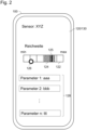
- Fig. 2 A display is shown after selecting the "XYZ" sensor. Once the sensor is selected, any adjustment of the detection threshold in the app may result in a resetting of the detection threshold in the selected motion sensor 200. However, it may also be necessary to actively set a new detection threshold in the app by activating a corresponding field.
- the Fig. 2 a scale 122 is shown, on which the intensity of the detection signal is displayed.
- the scale 122 ranges from a minimum to a maximum intensity, but can also refer to any desired intensity range.
- the fluctuation range 124 of the currently measured intensity is displayed on the scale 122 as a hatched area.
- the current intensity 125 is shown as a black bar.
- the displayed intensity 124, 125 depends on the distance of the operator 300 to the motion sensor 200. The closer the operator 300 is to the motion sensor 200, the closer to the maximum value is the displayed intensity 124, 125.
- the operator 300 can therefore establish a relationship between the range of the motion sensor 200 and the measured detection signal by displaying the detection signal or its intensity and his own position in the detection area 210.
- a representation of a slider 126 is superimposed on the representation of scale 122.
- the position of the slider 126 on scale 122 sets the detection threshold to the intensity corresponding to the position and transmits it to motion sensor 200. For example, if slider 126 is moved into the displayed intensity range 124, 125 using a corresponding gesture, this corresponds to setting a corresponding intensity threshold in motion sensor 200.
- This can also be considered a range adjustment, since movements at a distance greater than the distance at which the detection threshold was set will generate a lower intensity and therefore will not trigger an event. Conversely, movements at a shorter distance will result in a greater intensity and thus trigger an event.
- control device 100 which can be designed, for example, as a smartphone.
- further operating parameters of the motion detector 200 can be changed or adjusted by means of the control device 100. This is the case for the example of Fig. 2 represented by fields 128. Such parameters can be, for example, an activation period, a transmission frequency, an interface selection, and the like.
- the devices controlled by the motion sensor 200 such as lights, elevators, windows, doors (such as garage doors or department store doors), or the like, or their operating parameters, can also be controlled by means of the control device 100 via the motion sensor 200.
- These operating parameters can be transmitted to the control device 100, displayed there, and adjustable from there.
- the activation period or the brightness of a light after motion detection or a delay time between motion detection and activation of a motor for the elevator or door control can be set via the control device. This is done, for example, in the example of Fig. 2 in one of the fields 128, in which corresponding values for the operating parameters can be entered.
- control device 100 thus makes it possible to adapt a wide class of operating parameters of the motion detector 200 or of electrical devices that it controls.
- the devices and methods described above make it possible to carry out range adjustments of motion sensors in a simple, reliable and time-saving manner.
Landscapes
- Engineering & Computer Science (AREA)
- Computer Networks & Wireless Communication (AREA)
- Remote Sensing (AREA)
- Radar, Positioning & Navigation (AREA)
- General Physics & Mathematics (AREA)
- Physics & Mathematics (AREA)
- Human Computer Interaction (AREA)
- Signal Processing (AREA)
- General Engineering & Computer Science (AREA)
- Theoretical Computer Science (AREA)
- User Interface Of Digital Computer (AREA)
- Selective Calling Equipment (AREA)
- Radar Systems Or Details Thereof (AREA)
Claims (8)
- Appareil de commande portatif (100) pour commander un capteur de mouvement (200), comprenantdes moyens de communication (110) pour communiquer sans fil avec un capteur de mouvement (200), adaptés pour recevoir un signal de détection généré momentanément dans le capteur de mouvement (200) par le capteur de mouvement (200) pendant que l'appareil de commande (100) se trouve dans une zone de détection (210) du capteur de mouvement (200) ;des moyens d'affichage (120) pour afficher le signal de détection ; etdes moyens de saisie (130) pour régler une valeur seuil de détection, pour laquelle un mouvement est détecté par le capteur de mouvement (200), sur la base du signal de détection affiché ;les moyens de communication (110) étant en outre adaptés pour transmettre la valeur seuil de détection réglée au capteur de mouvement (200) en tant que valeur seuil de détection valide du capteur de mouvement (200),caractérisés en ce queles moyens d'affichage (120) sont adaptés pour afficher une intensité du signal de détection actuellement généré dans le détecteur de mouvement (200) sur une échelle (122) allant d'une intensité minimale à une intensité maximale ; et les moyens de saisie (130) sont adaptés pour régler la valeur seuil de détection sur une valeur d'intensité par rapport à la même échelle (122).
- Appareil de commande (100) selon la revendication 1, dans lequel les moyens d'affichage (120) et les moyens de saisie (130) sont combinés pour former un écran tactile.
- Appareil de commande (100) selon l'une des revendications précédentes, dans lequel
les moyens d'affichage (120) sont adaptés pour afficher la valeur seuil de détection réglée en plus du signal de détection. - Appareil de commande (100) selon l'une des revendications précédentes, dans lequelles moyens d'affichage (120) sont adaptés pour afficher d'autres paramètres de fonctionnement du capteur de mouvement (200) ou d'un appareil électrique commandé par le capteur de mouvement (200) ;les moyens de saisie (130) sont adaptés pour obtenir des réglages des autres paramètres de fonctionnement ; etles moyens de communication (110) sont adaptés pour transmettre les réglages obtenus des autres paramètres de fonctionnement au capteur de mouvement (200).
- Appareil de commande (100) selon l'une des revendications précédentes, dans lequel
les moyens de communication (110) sont conçus pour communiquer par radio. - Produit logiciel qui, lorsqu'il est exécuté sur un appareil portatif doté de moyens d'affichage (120), de moyens de saisie (130) et de moyens de communication (110), amène l'appareil à fonctionner comme appareil de commande (100) selon l'une des revendications précédentes.
- Système de détection de mouvement, comprenantun appareil de commande (100) selon l'une des revendications 1 à 5 ; etun capteur de mouvement (200), dont au moins une valeur seuil de détection des paramètres de fonctionnement peut être réglée par l'appareil de commande (100).
- Procédé de commande d'un capteur de mouvement (200) au moyen d'un appareil de commande (100) selon l'une des revendications 1 à 5, comprenantla détection d'un mouvement d'un opérateur (300) de l'appareil de commande (100) dans une zone de détection (210) du capteur de mouvement (200) par le capteur de mouvement (200) ;la réception et l'affichage par l'appareil de commande (100) du signal de détection généré par le capteur de mouvement (200) en raison du mouvement de l'opérateur (300) ;le réglage de la valeur seuil de détection sur le signal de détection affiché à l'aide de l'appareil de commande (100) afin de régler la portée du capteur de mouvement (200) sur la position de l'opérateur (300) ;la transmission de la valeur seuil de détection réglée au capteur de mouvement (200) en tant que valeur seuil de détection valide du capteur de mouvement (200).
Applications Claiming Priority (2)
| Application Number | Priority Date | Filing Date | Title |
|---|---|---|---|
| DE102019126496.0A DE102019126496A1 (de) | 2019-10-01 | 2019-10-01 | Tragbare Steuervorrichtung zum Steuern eines Bewegungssensors |
| PCT/EP2020/076051 WO2021063697A1 (fr) | 2019-10-01 | 2020-09-17 | Appareil de commande portatif pour commander un capteur de mouvement |
Publications (2)
| Publication Number | Publication Date |
|---|---|
| EP3877963A1 EP3877963A1 (fr) | 2021-09-15 |
| EP3877963B1 true EP3877963B1 (fr) | 2025-06-25 |
Family
ID=72615838
Family Applications (1)
| Application Number | Title | Priority Date | Filing Date |
|---|---|---|---|
| EP20776103.2A Active EP3877963B1 (fr) | 2019-10-01 | 2020-09-17 | Appareil de commande portatif pour commander un capteur de mouvement |
Country Status (5)
| Country | Link |
|---|---|
| US (1) | US20220345564A1 (fr) |
| EP (1) | EP3877963B1 (fr) |
| CN (1) | CN114097213B (fr) |
| DE (1) | DE102019126496A1 (fr) |
| WO (1) | WO2021063697A1 (fr) |
Families Citing this family (1)
| Publication number | Priority date | Publication date | Assignee | Title |
|---|---|---|---|---|
| DE102023126598A1 (de) | 2023-09-29 | 2025-04-03 | Audi Aktiengesellschaft | Kraftfahrzeug und Verfahren zur zeitlichen Steuerung eines Betriebs einer Recheneinrichtung eines Kraftfahrzeuges |
Citations (2)
| Publication number | Priority date | Publication date | Assignee | Title |
|---|---|---|---|---|
| GB2524029A (en) * | 2014-03-11 | 2015-09-16 | Novar Ed & S Ltd | Systems and methods for testing sensor units |
| US10156581B1 (en) * | 2016-06-10 | 2018-12-18 | Cooper Technologies Company | Motion sensor with automatically adjustable sensitivity |
Family Cites Families (6)
| Publication number | Priority date | Publication date | Assignee | Title |
|---|---|---|---|---|
| JP2002101165A (ja) * | 2000-07-17 | 2002-04-05 | 繁 ▲斉▼藤 | 近接センサー装置、携帯情報端末および無線通信システム |
| US20050128067A1 (en) * | 2003-12-11 | 2005-06-16 | Honeywell International, Inc. | Automatic sensitivity adjustment on motion detectors in security system |
| US8232909B2 (en) * | 2008-09-30 | 2012-07-31 | Cooper Technologies Company | Doppler radar motion detector for an outdoor light fixture |
| US9720555B2 (en) * | 2011-12-23 | 2017-08-01 | Gary SORDEN | Location-based services |
| US10143066B2 (en) * | 2016-02-23 | 2018-11-27 | MW McWong International, Inc. | Sensor with wireless device for controlling a light source |
| DE102016224330B4 (de) * | 2016-12-07 | 2025-08-07 | Tridonic Gmbh & Co Kg | Leuchte mit einem konfigurierbaren Sensor, mobile Vorrichtung zur Konfiguration und Kommissionierung des Sensors mittels Lichtsignalen |
-
2019
- 2019-10-01 DE DE102019126496.0A patent/DE102019126496A1/de active Pending
-
2020
- 2020-09-17 EP EP20776103.2A patent/EP3877963B1/fr active Active
- 2020-09-17 WO PCT/EP2020/076051 patent/WO2021063697A1/fr not_active Ceased
- 2020-09-17 US US17/763,393 patent/US20220345564A1/en not_active Abandoned
- 2020-09-17 CN CN202080048148.6A patent/CN114097213B/zh active Active
Patent Citations (2)
| Publication number | Priority date | Publication date | Assignee | Title |
|---|---|---|---|---|
| GB2524029A (en) * | 2014-03-11 | 2015-09-16 | Novar Ed & S Ltd | Systems and methods for testing sensor units |
| US10156581B1 (en) * | 2016-06-10 | 2018-12-18 | Cooper Technologies Company | Motion sensor with automatically adjustable sensitivity |
Also Published As
| Publication number | Publication date |
|---|---|
| DE102019126496A1 (de) | 2021-04-01 |
| US20220345564A1 (en) | 2022-10-27 |
| EP3877963A1 (fr) | 2021-09-15 |
| CN114097213A (zh) | 2022-02-25 |
| WO2021063697A1 (fr) | 2021-04-08 |
| CN114097213B (zh) | 2023-08-08 |
Similar Documents
| Publication | Publication Date | Title |
|---|---|---|
| EP2985636B1 (fr) | Procédé d'alignement d'un dispositif de capteurs | |
| EP3497529B1 (fr) | Procédé de fonctionnement d'un appareil de traitement de surface à déplacement autonome | |
| EP2784535B1 (fr) | Procédé de détection d'une variation des signaux à l'intérieur d'une zone de détection d'un capteur de présence ou de surveillance et dispositif de surveillance | |
| EP1946154B1 (fr) | Procede et unite de commande pour la configuration et la surveillance d'un dispositif a fonction de securite | |
| DE112017005038T5 (de) | Türöffnungs- und Schließvorrichtung | |
| EP3401698A1 (fr) | Procédé d'utilisation d'un appareil électroménager | |
| DE102007037980A1 (de) | Vorrichtung zum Messen der Körpergröße | |
| DE102015122925A1 (de) | Intelligentes Schaltersteuersystern und Verfahren zum Implernentieren des Intelligenten Schaltersteuersystems | |
| DE102014007177A1 (de) | System zum Steuern wenigstens eines Hausgerätes | |
| DE112017002359T5 (de) | Systeme und verfahren zum steuern des betriebes eines bewegbaren wandsystems | |
| WO2015051948A1 (fr) | Dispositif et procédé pour la reconnaissance d'un état | |
| EP3877963B1 (fr) | Appareil de commande portatif pour commander un capteur de mouvement | |
| DE10208469A1 (de) | Elektrisches Gerät, insbesondere Dunstabzugshaube | |
| DE10054627A1 (de) | Verfahren und Vorrichtung zum Ausrichten eines von einem Rotationslaser erzeugten Lichtstrahls | |
| DE102017116996B4 (de) | Inbetriebnahme und Konfiguration von mit Anlagen assoziierter Steuerelektronik | |
| EP2056125B1 (fr) | Capteur | |
| EP3265618B1 (fr) | Robinetterie hybride à reconnaissance de jet d'eau | |
| EP2934242B1 (fr) | Procédé de surveillance d'un appareil de cuisson et appareil de cuisson pourvu d'un capteur de température | |
| WO2021028462A9 (fr) | Procédé de commande d'une installation d'ascenseur à l'aide d'un dispositif mobile commandé par ordinateur | |
| WO2009046959A1 (fr) | Dispositif pour commander un élément mobile motorisé, en particulier une porte ou un portail | |
| EP3183632B1 (fr) | Dispositif de commande et appareil de commande mobile, en particulier pour appareil ménager électronique | |
| EP3336583B1 (fr) | Télémètre à laser | |
| DE102013103851A1 (de) | Verfahren zum Ansteuern von gebäudesystemtechnischen Aktoren | |
| DE102012109985A1 (de) | Optoelektronischer Sensor und Verfahren zur Veränderung von Sensoreinstellungen | |
| DE102014005752B3 (de) | Sensor zum Nachweis von Objekten in einem Überwachungsbereich |
Legal Events
| Date | Code | Title | Description |
|---|---|---|---|
| STAA | Information on the status of an ep patent application or granted ep patent |
Free format text: STATUS: UNKNOWN |
|
| STAA | Information on the status of an ep patent application or granted ep patent |
Free format text: STATUS: THE INTERNATIONAL PUBLICATION HAS BEEN MADE |
|
| PUAI | Public reference made under article 153(3) epc to a published international application that has entered the european phase |
Free format text: ORIGINAL CODE: 0009012 |
|
| STAA | Information on the status of an ep patent application or granted ep patent |
Free format text: STATUS: REQUEST FOR EXAMINATION WAS MADE |
|
| 17P | Request for examination filed |
Effective date: 20210609 |
|
| AK | Designated contracting states |
Kind code of ref document: A1 Designated state(s): AL AT BE BG CH CY CZ DE DK EE ES FI FR GB GR HR HU IE IS IT LI LT LU LV MC MK MT NL NO PL PT RO RS SE SI SK SM TR |
|
| STAA | Information on the status of an ep patent application or granted ep patent |
Free format text: STATUS: EXAMINATION IS IN PROGRESS |
|
| 17Q | First examination report despatched |
Effective date: 20220629 |
|
| DAV | Request for validation of the european patent (deleted) | ||
| DAX | Request for extension of the european patent (deleted) | ||
| P01 | Opt-out of the competence of the unified patent court (upc) registered |
Effective date: 20230512 |
|
| GRAP | Despatch of communication of intention to grant a patent |
Free format text: ORIGINAL CODE: EPIDOSNIGR1 |
|
| STAA | Information on the status of an ep patent application or granted ep patent |
Free format text: STATUS: GRANT OF PATENT IS INTENDED |
|
| INTG | Intention to grant announced |
Effective date: 20250117 |
|
| GRAS | Grant fee paid |
Free format text: ORIGINAL CODE: EPIDOSNIGR3 |
|
| GRAA | (expected) grant |
Free format text: ORIGINAL CODE: 0009210 |
|
| STAA | Information on the status of an ep patent application or granted ep patent |
Free format text: STATUS: THE PATENT HAS BEEN GRANTED |
|
| AK | Designated contracting states |
Kind code of ref document: B1 Designated state(s): AL AT BE BG CH CY CZ DE DK EE ES FI FR GB GR HR HU IE IS IT LI LT LU LV MC MK MT NL NO PL PT RO RS SE SI SK SM TR |
|
| REG | Reference to a national code |
Ref country code: GB Ref legal event code: FG4D Free format text: NOT ENGLISH |
|
| REG | Reference to a national code |
Ref country code: CH Ref legal event code: EP |
|
| REG | Reference to a national code |
Ref country code: CH Ref legal event code: EP |
|
| REG | Reference to a national code |
Ref country code: IE Ref legal event code: FG4D Free format text: LANGUAGE OF EP DOCUMENT: GERMAN |
|
| REG | Reference to a national code |
Ref country code: DE Ref legal event code: R096 Ref document number: 502020011303 Country of ref document: DE |
|
| PG25 | Lapsed in a contracting state [announced via postgrant information from national office to epo] |
Ref country code: FI Free format text: LAPSE BECAUSE OF FAILURE TO SUBMIT A TRANSLATION OF THE DESCRIPTION OR TO PAY THE FEE WITHIN THE PRESCRIBED TIME-LIMIT Effective date: 20250625 |
|
| PGFP | Annual fee paid to national office [announced via postgrant information from national office to epo] |
Ref country code: DE Payment date: 20250918 Year of fee payment: 6 |
|
| REG | Reference to a national code |
Ref country code: LT Ref legal event code: MG9D |
|
| PG25 | Lapsed in a contracting state [announced via postgrant information from national office to epo] |
Ref country code: NO Free format text: LAPSE BECAUSE OF FAILURE TO SUBMIT A TRANSLATION OF THE DESCRIPTION OR TO PAY THE FEE WITHIN THE PRESCRIBED TIME-LIMIT Effective date: 20250925 Ref country code: GR Free format text: LAPSE BECAUSE OF FAILURE TO SUBMIT A TRANSLATION OF THE DESCRIPTION OR TO PAY THE FEE WITHIN THE PRESCRIBED TIME-LIMIT Effective date: 20250926 |
|
| PG25 | Lapsed in a contracting state [announced via postgrant information from national office to epo] |
Ref country code: BG Free format text: LAPSE BECAUSE OF FAILURE TO SUBMIT A TRANSLATION OF THE DESCRIPTION OR TO PAY THE FEE WITHIN THE PRESCRIBED TIME-LIMIT Effective date: 20250625 |
|
| PGFP | Annual fee paid to national office [announced via postgrant information from national office to epo] |
Ref country code: GB Payment date: 20250929 Year of fee payment: 6 |
|
| PG25 | Lapsed in a contracting state [announced via postgrant information from national office to epo] |
Ref country code: HR Free format text: LAPSE BECAUSE OF FAILURE TO SUBMIT A TRANSLATION OF THE DESCRIPTION OR TO PAY THE FEE WITHIN THE PRESCRIBED TIME-LIMIT Effective date: 20250625 |
|
| PGFP | Annual fee paid to national office [announced via postgrant information from national office to epo] |
Ref country code: FR Payment date: 20250925 Year of fee payment: 6 |
|
| PG25 | Lapsed in a contracting state [announced via postgrant information from national office to epo] |
Ref country code: RS Free format text: LAPSE BECAUSE OF FAILURE TO SUBMIT A TRANSLATION OF THE DESCRIPTION OR TO PAY THE FEE WITHIN THE PRESCRIBED TIME-LIMIT Effective date: 20250925 |
|
| PG25 | Lapsed in a contracting state [announced via postgrant information from national office to epo] |
Ref country code: LV Free format text: LAPSE BECAUSE OF FAILURE TO SUBMIT A TRANSLATION OF THE DESCRIPTION OR TO PAY THE FEE WITHIN THE PRESCRIBED TIME-LIMIT Effective date: 20250625 |
|
| REG | Reference to a national code |
Ref country code: NL Ref legal event code: MP Effective date: 20250625 |
|
| PG25 | Lapsed in a contracting state [announced via postgrant information from national office to epo] |
Ref country code: NL Free format text: LAPSE BECAUSE OF FAILURE TO SUBMIT A TRANSLATION OF THE DESCRIPTION OR TO PAY THE FEE WITHIN THE PRESCRIBED TIME-LIMIT Effective date: 20250625 |
|
| PG25 | Lapsed in a contracting state [announced via postgrant information from national office to epo] |
Ref country code: PT Free format text: LAPSE BECAUSE OF FAILURE TO SUBMIT A TRANSLATION OF THE DESCRIPTION OR TO PAY THE FEE WITHIN THE PRESCRIBED TIME-LIMIT Effective date: 20251027 |
|
| PG25 | Lapsed in a contracting state [announced via postgrant information from national office to epo] |
Ref country code: IS Free format text: LAPSE BECAUSE OF FAILURE TO SUBMIT A TRANSLATION OF THE DESCRIPTION OR TO PAY THE FEE WITHIN THE PRESCRIBED TIME-LIMIT Effective date: 20251025 |
|
| PG25 | Lapsed in a contracting state [announced via postgrant information from national office to epo] |
Ref country code: SM Free format text: LAPSE BECAUSE OF FAILURE TO SUBMIT A TRANSLATION OF THE DESCRIPTION OR TO PAY THE FEE WITHIN THE PRESCRIBED TIME-LIMIT Effective date: 20250625 |
|
| PG25 | Lapsed in a contracting state [announced via postgrant information from national office to epo] |
Ref country code: CZ Free format text: LAPSE BECAUSE OF FAILURE TO SUBMIT A TRANSLATION OF THE DESCRIPTION OR TO PAY THE FEE WITHIN THE PRESCRIBED TIME-LIMIT Effective date: 20250625 |
|
| PG25 | Lapsed in a contracting state [announced via postgrant information from national office to epo] |
Ref country code: PL Free format text: LAPSE BECAUSE OF FAILURE TO SUBMIT A TRANSLATION OF THE DESCRIPTION OR TO PAY THE FEE WITHIN THE PRESCRIBED TIME-LIMIT Effective date: 20250625 |
|
| PG25 | Lapsed in a contracting state [announced via postgrant information from national office to epo] |
Ref country code: EE Free format text: LAPSE BECAUSE OF FAILURE TO SUBMIT A TRANSLATION OF THE DESCRIPTION OR TO PAY THE FEE WITHIN THE PRESCRIBED TIME-LIMIT Effective date: 20250625 |
|
| PG25 | Lapsed in a contracting state [announced via postgrant information from national office to epo] |
Ref country code: SK Free format text: LAPSE BECAUSE OF FAILURE TO SUBMIT A TRANSLATION OF THE DESCRIPTION OR TO PAY THE FEE WITHIN THE PRESCRIBED TIME-LIMIT Effective date: 20250625 |
|
| PG25 | Lapsed in a contracting state [announced via postgrant information from national office to epo] |
Ref country code: ES Free format text: LAPSE BECAUSE OF FAILURE TO SUBMIT A TRANSLATION OF THE DESCRIPTION OR TO PAY THE FEE WITHIN THE PRESCRIBED TIME-LIMIT Effective date: 20250625 |
|
| PG25 | Lapsed in a contracting state [announced via postgrant information from national office to epo] |
Ref country code: RO Free format text: LAPSE BECAUSE OF FAILURE TO SUBMIT A TRANSLATION OF THE DESCRIPTION OR TO PAY THE FEE WITHIN THE PRESCRIBED TIME-LIMIT Effective date: 20250625 |
|
| PG25 | Lapsed in a contracting state [announced via postgrant information from national office to epo] |
Ref country code: DK Free format text: LAPSE BECAUSE OF FAILURE TO SUBMIT A TRANSLATION OF THE DESCRIPTION OR TO PAY THE FEE WITHIN THE PRESCRIBED TIME-LIMIT Effective date: 20250625 |
|
| PG25 | Lapsed in a contracting state [announced via postgrant information from national office to epo] |
Ref country code: IT Free format text: LAPSE BECAUSE OF FAILURE TO SUBMIT A TRANSLATION OF THE DESCRIPTION OR TO PAY THE FEE WITHIN THE PRESCRIBED TIME-LIMIT Effective date: 20250625 |
|
| REG | Reference to a national code |
Ref country code: CH Ref legal event code: H13 Free format text: ST27 STATUS EVENT CODE: U-0-0-H10-H13 (AS PROVIDED BY THE NATIONAL OFFICE) Effective date: 20260425 |
|
| PLBE | No opposition filed within time limit |
Free format text: ORIGINAL CODE: 0009261 |
|
| STAA | Information on the status of an ep patent application or granted ep patent |
Free format text: STATUS: NO OPPOSITION FILED WITHIN TIME LIMIT |