EP3878268B1 - Rahmenanordnung für eine landwirtschaftliche rundballenpresse - Google Patents
Rahmenanordnung für eine landwirtschaftliche rundballenpresse Download PDFInfo
- Publication number
- EP3878268B1 EP3878268B1 EP21161889.7A EP21161889A EP3878268B1 EP 3878268 B1 EP3878268 B1 EP 3878268B1 EP 21161889 A EP21161889 A EP 21161889A EP 3878268 B1 EP3878268 B1 EP 3878268B1
- Authority
- EP
- European Patent Office
- Prior art keywords
- frame
- roller
- pair
- mount
- baler
- Prior art date
- Legal status (The legal status is an assumption and is not a legal conclusion. Google has not performed a legal analysis and makes no representation as to the accuracy of the status listed.)
- Active
Links
Images


Classifications
-
- A—HUMAN NECESSITIES
- A01—AGRICULTURE; FORESTRY; ANIMAL HUSBANDRY; HUNTING; TRAPPING; FISHING
- A01F—PROCESSING OF HARVESTED PRODUCE; HAY OR STRAW PRESSES; DEVICES FOR STORING AGRICULTURAL OR HORTICULTURAL PRODUCE
- A01F15/00—Baling presses for straw, hay or the like
- A01F15/08—Details
-
- A—HUMAN NECESSITIES
- A01—AGRICULTURE; FORESTRY; ANIMAL HUSBANDRY; HUNTING; TRAPPING; FISHING
- A01F—PROCESSING OF HARVESTED PRODUCE; HAY OR STRAW PRESSES; DEVICES FOR STORING AGRICULTURAL OR HORTICULTURAL PRODUCE
- A01F15/00—Baling presses for straw, hay or the like
- A01F15/07—Rotobalers, i.e. machines for forming cylindrical bales by winding and pressing
-
- A—HUMAN NECESSITIES
- A01—AGRICULTURE; FORESTRY; ANIMAL HUSBANDRY; HUNTING; TRAPPING; FISHING
- A01F—PROCESSING OF HARVESTED PRODUCE; HAY OR STRAW PRESSES; DEVICES FOR STORING AGRICULTURAL OR HORTICULTURAL PRODUCE
- A01F15/00—Baling presses for straw, hay or the like
- A01F15/07—Rotobalers, i.e. machines for forming cylindrical bales by winding and pressing
- A01F2015/0795—Pressing chamber with variable volume
Definitions
- the present invention pertains to agricultural round balers and, more specifically, to a structural framework of an agricultural round baler.
- an agricultural round baler for baling crop material in a field.
- the agricultural round baler includes a plurality of rollers defining a bale chamber, a tail gate, and a frame assembly.
- the frame assembly includes a main frame and a pair of frame modules removably connected to the main frame.
- Each frame module of the pair of frame modules includes at least one roller mount and a tail gate mount defining a pivot axis of the tail gate.
- At least one roller of the plurality of rollers is mounted to the at least one roller mount and the tail gate is pivotally mounted to the tail gate mount.
- the pair of frame modules defines a baler size for producing a correspondingly sized round bale.
- One possible advantage of the exemplary embodiment of the frame assembly of the agricultural baler is that the interchangeable frame modules contain all the necessary changes between bale sizes, which significantly reduces the complexity and cost in manufacturing variously sized balers.
- forward when used in connection with the agricultural baler and/or components thereof are usually determined with reference to the direction of forward operative travel of the towing vehicle, but they should not be construed as limiting.
- longitudinal and “transverse” are determined with reference to the fore-and-aft direction of the towing vehicle and are equally not to be construed as limiting.
- FIG. 1 there is shown a cross-sectional, side view of a known round baler 10 which may be towed by a vehicle 14 in a forward direction of travel F.
- the vehicle 14 may be any desired vehicle, such as an agricultural vehicle in the form of a tractor 14.
- Crop material is lifted from windrows into the baler 10 by a pickup unit 16.
- the pickup unit 16 includes a rotating pickup reel 18 with tine bars and tines 20, which move the crop rearward toward a variable bale chamber 22.
- the reel 18 is rotatable in an operating direction for lifting the crop material off of the ground and a reverse direction, i.e., opposite to the operating direction.
- the bale chamber 22 is configured as a variable bale chamber 22 which includes multiple rolls or rollers 24, 26, such as various stationary rollers 24 and movable rollers 26, actuators and pivot arms coupled to the movable rollers 26, and at least one belt 28.
- the rollers 24, 26 may comprise a floor roller, starter roller, fixed roller(s), pivot roller(s), stripper roller, and/or follower roller(s). Together, the rollers 24, 26 and the belt(s) 28 create a round circulating chamber 22 which expands in between an empty bale position and a full bale position for engaging and rolling the bale.
- the bale grows inside the chamber 22 it begins to act upon the belts 28 such that the belts 28 pull against the pivot arms which in turn causes the movable rollers 26 to move upwardly so that the variable bale chamber 22 incrementally expands with the size of the bale.
- the bale When the bale reaches a predetermined size, the bale is wrapped with a wrapping material (e.g., mesh or twine) by a wrapper. Then, once fully wrapped, the bale is ejected out of the tail gate 12.
- the tail gate 12 may pivot upwardly about pivot axis 30 to open the bale chamber 22. Then, the bale rolls out of the bale chamber 22 and onto a bale ejector or kicker 32, which pushes the bale rearwardly away from the baler 10 so that the tail gate 12 may downwardly pivot unencumbered by the ejected bale.
- the baler 10 can further include an electrical processing circuit 34, e.g. controller 34 with a memory 36, for conducting various baling procedures.
- the controller 34 can be configured for carrying out the bale discharge operation.
- the controller 34 may open the tail gate 12 via accompanying actuators upon sensing a full bale condition by a bale-size sensor.
- the baler 10 has a main frame 38 which supports the various components of the baler 10, including the roller fixation points, drives, and tail gate pivot point 30.
- the main frame 38 is a single or one-size main frame 38.
- the main frame 38 which may be a welded construction, is a one-size main frame 38 which dictates the size of the bale chamber 22.
- the main frame 38 also dictates the size of the bale which is produced by the bale chamber 22.
- variously sized balers which produce differently sized bales each have a differing main frame.
- designing a different main frame for each size of bale may place a significant burden on the manufacturing company which manufactures the baler. For instance, designing several main frame structures may take additional design time, test time, and increase the manufacturing tooling investment and complexity.
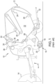
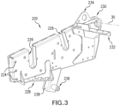
- FIGS. 2-3 there is shown an embodiment of a round baler 200 with a frame assembly 210 that includes a standardized or universal main frame 212 and a pair of interchangeable frame modules 220, 222 for tailoring the baler size of the round baler 200, i.e., the size of the bale produced by the round baler 200.
- the round baler 200 may be substantially similar to the round baler 10 as described above, except that the round baler 200 includes the frame assembly 210 instead of the one-size main frame 38.
- the frame assembly 210 supports the various components of the round baler 200.
- the frame assembly 210 supports the roller drive architecture including the conveyor 201, e.g. drive chain 201, and sprockets 202, 203 coupled to the drive chain 201, fixed and idler rollers 204, 205 operably connected to the sprockets 202, and the tail gate 206.
- the main frame 212 may comprise a welded construction of one or more component.
- the upper portion on each side of the main frame 212 may include a recess or cutout for accommodating the frame module 220, 222.
- the main frame 212 may comprise any desired material, such as metal and/or plastic.
- Each frame module 220, 222 is removably connected to the main frame 212.
- each frame module 220, 222 may include one or more receiving holes 224 for receiving corresponding fastener(s), such as bolts and/or screws, that removably attach each respective frame module 220, 222 to the corresponding sides of the main frame 212.
- the left and right frame modules 220, 222 may substantially mirror one another, except that the left frame module 220 may include additional mounting features for supporting the roller drive architecture of the round baler 200.
- both frame modules 220, 222 may include at least one roller mount 226, 228 for mounting any desired roller 204, 205, a tail gate mount 230 defining the pivot point 30, i.e., axis, of the tail gate 206, a side panel mount 232 for mounting a respective side panel of round baler 200, and a lift-hook mounting point 234 for receiving a lift hook to lift the round baler 200.
- the left frame module 220 as viewed in the forward direction of travel, further includes a chain mount 236 to which the chain sprocket 203 and drive chain 201 are mounted.
- each frame module 220, 222 may collectively support the drive chain 201, sprockets 202, 203, fixed and idler rollers 204, 205, and the tail gate 206.
- the body of each frame module 220, 222 may comprise one or more components and any desired material.
- the frame modules 220, 222 may correspond to a 1.65 meter-sized baler (5.4 foot-sized baler).
- the at least one roller mount 226, 228 of each frame module 220, 222 mounts at least one roller 204, 205.
- the at least one roller mount 226 may include two fixed-roller mounts 226 for respectively mounting two fixed rollers 204 and a single idler roller mount 228 for mounting the idler roller 205.
- the roller mounts 226, 228 may define and set the roller fixation points of the fixed and idler rollers 204, 205.
- Each fixed roller mount 226 may comprise an open recess and/or accompanying brackets for receiving and connecting the fixed rollers 204 to the body of the frame module 220, 222.
- the idler roller mount 228 may comprise an opening and/or accompanying bracket for connecting the idler roller to the body of the frame module 220, 222.
- the set locations of the rollers 204, 205 on the frame modules 220, 222 in part determines the size of bale which is producible by the round baler 200.
- the tail gate mount 230 may be connected to the upper, rear end of each frame module 220, 222.
- the tail gate mount 230 defines the pivot axis 30 of the tail gate 206, which thereby helps to define the overall size of the bale which may be ejected by the round baler 200.
- Each tail gate mount 230 may comprise a through hole, within a designated portion, e.g. plate, of the frame module 220, 222, for receiving a mounting bar of the tail gate 206.
- each frame module 220, 222 may be located adjacent to the tail gate mount 230. As shown, each side panel mount 232 may comprise a bracket which extends outwardly from the surface of the frame module 220, 222. Yet, the side panel mounts 232 may or may not extend beyond the surface of the frame module 220, 222. The side panel mounts 232 may mount any desired side panels which correspond to a desired baler size.
- Each lift-hook mounting point 234 is located at the top of each frame module 220, 222.
- Each lift-hook mounting point 234 may comprise a receiving hole, within a designated portion, e.g. plate, of the frame module 220, 222, for receiving a respective lift hook in order to lift the round baler 200. It should be appreciated that each frame module 220, 222 may or may not include a lift-hook mounting point 234.
- the left frame module 220 may additionally include one or more mounting features for mounting the roller drive architecture, e.g. drive chain 201 and sprockets 202, 203, of the round baler 200.
- the left frame module 220 may further include a chain mount 236 and a downwardly extending protrusion 238 upon which the chain mount 236 is connected.
- the chain mount rotatably supports the chain sprocket 203.
- the chain mount 236 may be located at the bottom of the frame module 220, underneath the roller mounts 226, 228.
- the chain mount 236 may comprise a rod that extends outwardly from the body of the frame module 220.
- the chain mount 236 extends outwardly and perpendicularly from the protrusion 238.
- the chain mount 236 may further include one or more brackets and/or fasteners for securing the chain sprocket 203 to the frame module 220.
- the protrusion 238 may be a part of the body of the frame module 220, or alternatively, the protrusion may be a separate component which is affixed to the body of the frame module 220.
- the protrusion 238 may be in the form of a beam connected to the body of the frame module 220.
- the protrusion 238 may comprise any desired material.
- the left frame module 220 may include more than one chain mount 236 may include any desired number of sprockets 202, 203 for support the drive chain 201 and/or driving any desired number of rollers 204, 205.
- the pair of frame modules 420, 422 may be substantially similar to the frame modules 220, 222, except that the frame modules 420, 422 have a differing mounting architecture in order to procedure a differently sized baler for producing a correspondingly sized bale.
- the frame modules 420, 422 may have an extended body that is taller than the body of the frame modules 220, 222.
- the frame modules 420, 422 may have a differently located idler roller mount 428.
- the left frame module 420 may not include a protrusion 238; and hence, the chain mount 426 may be located within the body of the frame module 420.
- a desired set of frame modules 220, 222, 420, 422 may be connected to the main frame 212 at the time of manufacture of the baler 200, or the frame modules 220, 222 may be interchanged with another set of frame modules 420, 422 after the sale of the baler 200.
- a farmer may alter the size of his current baler 200 by buying new frame modules 420, 422 and accordingly interchanging the existing frame modules 220, 222 with the new frame modules 420, 422 to achieve a desired baler size.
- the farmer may also need to alter the belt sizes in order to achieve a differently sized bale chamber for producing a correspondingly sized bale.
Landscapes
- Life Sciences & Earth Sciences (AREA)
- Environmental Sciences (AREA)
- Storage Of Harvested Produce (AREA)
- Harvesting Machines For Specific Crops (AREA)
Claims (10)
- Landwirtschaftliche Rundballenpresse (200) zum Pressen von Ballen aus Erntegut auf einem Feld mit:einer Mehrzahl von Walzen (204, 205), die eine Ballenpresskammer definieren;einer Heckklappe (206); undeiner Rahmenanordnung (210) mit:einem Hauptrahmen (212), unddadurch gekennzeichnet, dassdie Rahmenanordnung (210) des Weiteren ein Paar von Rahmenmodulen (220, 222) aufweist, die eine Ballengröße zur Herstellung eines entsprechenden dimensionierten Rundballens definieren, wobei das Paar von Rahmenmodulen (220, 222) lösbar mit dem Hauptrahmen (212) verbunden ist, wobei jedes Rahmenmodul (220, 222) des Paars von Rahmenmodulen (220, 222) zumindest eine Walzenbefestigung (226, 228) und eine Heckklappenbefestigung (230) aufweist, die eine Schwenkachse der Heckklappe (206) definiert,wobei die zumindest eine Walze (204, 205) der Mehrzahl von Walzen (204, 205) an der zumindest einen Walzenbefestigung (226, 228) befestigt ist,wobei die Heckklappe (206) schwenkbar an der Heckklappenbefestigung (230) befestigt ist.
- Landwirtschaftliche Rundballenpresse (200) nach Anspruch 1, wobei das Paar von Rahmenmodulen (220) dazu eingerichtet ist, mit einem anderen sich unterscheidenden Paar von Rahmenmodulen (222) austauschbar zu sein, um eine unterschiedliche Rundballenpressengröße der landwirtschaftlichen Rundballenpresse (200) zu definieren.
- Landwirtschaftliche Rundballenpresse (200) nach einem der vorhergehenden Ansprüche, wobei die zumindest eine Walzenbefestigung (226, 228) einen Walzenbefestigungspunkt der zumindest einen Walze (204, 205) der Mehrzahl von Walzen (204, 205) festlegt.
- Landwirtschaftliche Rundballenpresse (200) nach einem der vorhergehenden Ansprüche, die des Weiteren eine Antriebskette (201) zum Antreiben der zumindest einen Walze (204, 205) der Mehrzahl von Walzen (204, 205) aufweist, wobei ein Rahmenmodul (220, 222) des Paars von Rahmenmodulen (220, 222) des Weiteren eine Kettenbefestigung (236) aufweist, an der die Antriebskette (201) befestigt ist.
- Landwirtschaftliche Rundballenpresse (200) nach einem der vorhergehenden Ansprüche, wobei die Mehrzahl von Walzen (204, 205) eine erste feststehende Walze (204) und eine zweite feststehende Walze (204) aufweist, wobei die zumindest eine Walzenbefestigung (226, 228) eine erste Walzenbefestigung (226), die dazu eingerichtet ist, die erste feststehende Walze (204) zu befestigen, und eine zweite Walzenbefestigung (228) aufweist, die dazu eingerichtet ist, die zweite feststehende Walze (204) zu befestigen.
- Landwirtschaftliche Rundballenpresse (200) nach Anspruch 5, wobei die Mehrzahl von Walzen (204, 205) des Weiteren eine Freilaufwalze (205) aufweist, wobei die zumindest eine Walzenbefestigung (226, 228) des Weiteren eine Freilaufwalzen-Befestigung (228) aufweist, die dazu eingerichtet ist, die Freilaufwalze (205) zu befestigen.
- Landwirtschaftliche Rundballenpresse (200) nach einem der vorhergehenden Ansprüche, wobei jedes Rahmenmodul (220, 222) des Paars von Rahmenmodulen (220, 222) des Weiteren einen Hebehaken-Befestigungspunkt (234) aufweist.
- Landwirtschaftliche Rundballenpresse (200) nach einem der vorhergehenden Ansprüche, die des Weiteren ein Paar von Seitenwänden aufweist, wobei jedes Rahmenmodul (220, 222) des Paars von Rahmenmodulen (220, 222) des Weiteren eine Seitenwand-Befestigung (232) aufweist, die dazu eingerichtet ist, eine entsprechende Seitenwand des Paars von Seitenwänden zu befestigen.
- Landwirtschaftliche Rundballenpresse (200) nach einem der vorhergehenden Ansprüche, wobei jedes Rahmenmodul (220, 222) des Paars von Rahmenmodulen (220, 222) des Weiteren zumindest ein Durchgangsloch (224) zur Aufnahme zumindest eines Befestigungsmittels zur lösbaren Verbindung jedes Rahmenmoduls (220, 222) des Paars von Rahmenmodulen (220, 222) mit dem Hauptrahmen (212) aufweist.
- Landwirtschaftliche Rundballenpresse (200) nach einem der vorhergehenden Ansprüche, wobei der Hauptrahmen (212) eine erste Seite und eine zweite Seite aufweist, wobei das Paar von Rahmenmodulen (220, 222) ein erstes Rahmenmodul (220, 222), das lösbar mit der ersten Seite des Hauptrahmens (212) verbunden ist, und ein zweites Rahmenmodul (220, 222) aufweist, das lösbar mit der zweiten Seite des Hauptrahmens (212) verbunden ist.
Applications Claiming Priority (1)
| Application Number | Priority Date | Filing Date | Title |
|---|---|---|---|
| US16/815,726 US11547056B2 (en) | 2020-03-11 | 2020-03-11 | Frame assembly for an agricultural round baler |
Publications (2)
| Publication Number | Publication Date |
|---|---|
| EP3878268A1 EP3878268A1 (de) | 2021-09-15 |
| EP3878268B1 true EP3878268B1 (de) | 2024-11-20 |
Family
ID=74870784
Family Applications (1)
| Application Number | Title | Priority Date | Filing Date |
|---|---|---|---|
| EP21161889.7A Active EP3878268B1 (de) | 2020-03-11 | 2021-03-10 | Rahmenanordnung für eine landwirtschaftliche rundballenpresse |
Country Status (2)
| Country | Link |
|---|---|
| US (1) | US11547056B2 (de) |
| EP (1) | EP3878268B1 (de) |
Families Citing this family (1)
| Publication number | Priority date | Publication date | Assignee | Title |
|---|---|---|---|---|
| US20250072333A1 (en) * | 2023-09-01 | 2025-03-06 | Cnh Industrial America Llc | Serpentine pivot roll |
Family Cites Families (50)
| Publication number | Priority date | Publication date | Assignee | Title |
|---|---|---|---|---|
| US4321787A (en) | 1975-06-09 | 1982-03-30 | Hesston Corporation | Method and apparatus for making large round crop bales |
| US4228638A (en) * | 1978-10-26 | 1980-10-21 | Deere & Company | Preservative applicator for a round baler |
| US4375187A (en) * | 1981-07-13 | 1983-03-01 | The Paul Revere Corporation | Ejection mechanism for a round baler |
| FR2517929A1 (fr) | 1981-12-10 | 1983-06-17 | Sicahn | Modification d'une presse a balles rondes permettant le ramassage et l'enroulage en direct de l'andain de lin dans le champ |
| GB2137925B (en) | 1983-03-29 | 1986-02-12 | Sperry Nv | Agricultural balers |
| DE3311330C2 (de) * | 1983-03-29 | 1986-10-30 | Claas Ohg, 4834 Harsewinkel | Verfahren und Vorrichtung zum Aufwickeln und Umhüllen eines zylindrischen Erntegutballens |
| DE3331671C2 (de) * | 1983-09-02 | 1994-05-26 | Claas Ohg | Großballenpresse für landwirtschaftliches Erntegut |
| NL192596C (nl) * | 1983-12-01 | 1997-11-04 | Texas Industries Inc | Rijdbare inrichting voor het vormen van ronde balen. |
| NL8304137A (nl) * | 1983-12-01 | 1985-07-01 | Lely Nv C Van Der | Inrichting voor het vormen van balen gewas. |
| DE3431389C2 (de) * | 1984-08-25 | 1994-03-17 | Claas Ohg | Verfahren zum Umschlingen eines Rundballens aus Erntegut |
| US4698955A (en) * | 1986-02-18 | 1987-10-13 | Wagstaff Robert A | Bale density control system for round balers |
| GB2203986B (en) * | 1987-04-27 | 1990-12-19 | Deere & Co | Machine for forming cylindrical bales of crop |
| DE3734850A1 (de) * | 1987-10-14 | 1989-04-27 | Zweegers & Zonen P J | Verfahren zum herstellen von erntegut-rollballen sowie vorrichtung zum durchfuehren des verfahrens |
| US4870812A (en) * | 1988-04-27 | 1989-10-03 | Ford New Holland, Inc. | Round baler with variable bale chamber |
| US5255501A (en) * | 1992-02-28 | 1993-10-26 | Mcwilliams Alexander | Baler for forming cylindrical bales |
| US5367865A (en) * | 1993-08-13 | 1994-11-29 | Ford New Holland, Inc. | Round baler apron tensioning apparatus |
| US6098391A (en) * | 1998-05-08 | 2000-08-08 | New Holland North America, Inc. | Round bale forming apparatus |
| US6021622A (en) * | 1998-06-19 | 2000-02-08 | New Holland North America, Inc. | Round bale wrapping apparatus |
| GB9826678D0 (en) * | 1998-12-04 | 1999-01-27 | Kverneland Naerbo As | Combined baler/bale wrapper apparatus |
| DE10006384A1 (de) * | 2000-02-12 | 2001-08-16 | Deere & Co | Rundballenpresse |
| US6591743B2 (en) * | 2001-02-01 | 2003-07-15 | Deere & Company | Cotton processing system and method of operation |
| DE10120124C2 (de) | 2001-04-25 | 2003-04-30 | Krone Bernhard Gmbh Maschf | Landwirtschaftliche Erntemaschine |
| JP3976552B2 (ja) * | 2001-11-19 | 2007-09-19 | 株式会社タカキタ | ロールベーラ |
| JP3843056B2 (ja) * | 2002-10-18 | 2006-11-08 | 株式会社タカキタ | ロールベーラ |
| DE602004026028D1 (de) * | 2004-01-27 | 2010-04-29 | Deere & Co | Ballenpresse |
| DE102004022801A1 (de) * | 2004-05-08 | 2005-12-15 | Deere & Company, Moline | Rundballenpresse |
| US7937923B2 (en) * | 2007-10-25 | 2011-05-10 | Deere & Company | Tractor and round baler combination with automatic baling and automatic rear door opening |
| EP2113165B1 (de) * | 2008-04-30 | 2011-08-24 | Deere & Company | Bahnwicklungsvorrichtung |
| US7908822B2 (en) * | 2008-05-15 | 2011-03-22 | Cnh America Llc | Computer controlled automatic wrapping material dispensing system for a round baler |
| ATE514330T1 (de) * | 2008-07-31 | 2011-07-15 | Deere & Co | Ballenpresse und einwicklerkombination |
| US8656686B2 (en) * | 2010-01-22 | 2014-02-25 | Cnh America Llc | Up-cut net knife for agricultural baler |
| US8677724B2 (en) * | 2010-10-25 | 2014-03-25 | Deere & Company | Round baler for baling crop residue |
| WO2013014291A1 (en) * | 2011-07-28 | 2013-01-31 | Varley Seamus | A round baling apparatus |
| US9295198B2 (en) * | 2012-05-09 | 2016-03-29 | Cnh Industrial America Llc | Density system bypass for a round baler |
| US9402347B2 (en) | 2013-03-12 | 2016-08-02 | Cnh Industrial America Llc | Baler rear shield mechanism |
| US8746137B1 (en) * | 2013-03-15 | 2014-06-10 | Cnh Industrial Canada, Ltd. | Calibration of baler tailgate cycle speed |
| US8776679B1 (en) * | 2013-03-15 | 2014-07-15 | Cnh Industrial Canada, Ltd. | Semi-automatic bale ejection sequence |
| EP3003008B1 (de) * | 2013-05-30 | 2021-01-27 | CNH Industrial Belgium N.V. | Ballenauswurfelement und verfahren zur verwendung |
| CN108243732A (zh) | 2017-12-31 | 2018-07-06 | 河南省颍骏机械制造有限公司 | 秸秆收获粉碎集揉强制喂入圆草捆压捆机 |
| US10986785B2 (en) * | 2018-06-26 | 2021-04-27 | Cnh Industrial America Llc | Continuous round baler and methods of using the same |
| AR112552A1 (es) * | 2018-07-12 | 2019-11-13 | Carlos Mainero Y Cia S A I C F I | Mecanismo para el atado de bordes de fardos en rollos |
| AR112554A1 (es) * | 2018-07-12 | 2019-11-13 | Carlos Mainero Y Cia S A I C F I | Mecanismo alimentador de material de atado de fardos en rollos |
| US11272669B2 (en) * | 2019-10-10 | 2022-03-15 | Cnh Industrial America Llc | Draper pickup with crop distribution for agricultural baler |
| US11589514B2 (en) * | 2019-10-30 | 2023-02-28 | Cnh Industrial America Llc | Pickup drive system for an agricultural baler |
| US11596105B2 (en) * | 2019-10-30 | 2023-03-07 | Cnh Industrial America Llc | Drive system for an agricultural baler |
| US11483979B2 (en) * | 2019-11-07 | 2022-11-01 | Cnh Industrial America Llc | Double-tab baffle for an agricultural baler |
| US11716936B2 (en) * | 2019-11-15 | 2023-08-08 | Cnh Industrial America Llc | Round baler with movable follower rolls |
| US11612108B2 (en) * | 2019-12-16 | 2023-03-28 | Cnh Industrial America Llc | Hydraulic system for agricultural baler |
| US11140827B2 (en) * | 2020-01-17 | 2021-10-12 | Cnh Industrial Canada, Ltd. | Round bale aligner and accumulator |
| US11576309B2 (en) * | 2020-02-27 | 2023-02-14 | Cnh Industrial America Llc | System and method for cleaning a cutting assembly of an agricultural baler |
-
2020
- 2020-03-11 US US16/815,726 patent/US11547056B2/en active Active
-
2021
- 2021-03-10 EP EP21161889.7A patent/EP3878268B1/de active Active
Also Published As
| Publication number | Publication date |
|---|---|
| US11547056B2 (en) | 2023-01-10 |
| US20210282330A1 (en) | 2021-09-16 |
| EP3878268A1 (de) | 2021-09-15 |
Similar Documents
| Publication | Publication Date | Title |
|---|---|---|
| US11547053B2 (en) | Agricultural vehicle with windguard having offset arms | |
| US9913433B2 (en) | Selectable knife tray arrangement | |
| US10827684B2 (en) | Mobile agricultural wrapping system and method | |
| US12302796B2 (en) | Draper pickup with crop distribution for agricultural baler | |
| EP3864952B1 (de) | Landwirtschaftliche ballenpresse mit system zur minderung der klingenüberlastung | |
| EP3847885B1 (de) | Landwirtschaftliche ballenpresse mit unabhängigen spannarmen | |
| US6745681B2 (en) | Light discharge gate for large round baler | |
| EP0286776A1 (de) | Aufnahme-Trommel und Rundballenpresse | |
| EP3878268B1 (de) | Rahmenanordnung für eine landwirtschaftliche rundballenpresse | |
| EP3269228B1 (de) | Netzwickelsystem | |
| EP3871489A1 (de) | Landwirtschaftliches fahrzeug mit verstellbarer aufnahme | |
| US11716936B2 (en) | Round baler with movable follower rolls | |
| US11483979B2 (en) | Double-tab baffle for an agricultural baler | |
| EP4205533B1 (de) | Landwirtschaftliche ballenpresse mit greifender ballenfreigaberampe | |
| US20250151655A1 (en) | Windguard assembly for agricultural baler | |
| EP3322282B1 (de) | Landwirtschaftliche ballenpresse mit einer zweiteiligen heckklappenanordnung und auswurfabfolgeverfahren | |
| US20250151656A1 (en) | Windguard assembly for agricultural baler | |
| US20240423138A1 (en) | Consistent flow windguard for agricultural baler | |
| US20250072333A1 (en) | Serpentine pivot roll | |
| US11690323B2 (en) | Agricultural baler with pivotable roll having external portion |
Legal Events
| Date | Code | Title | Description |
|---|---|---|---|
| PUAI | Public reference made under article 153(3) epc to a published international application that has entered the european phase |
Free format text: ORIGINAL CODE: 0009012 |
|
| STAA | Information on the status of an ep patent application or granted ep patent |
Free format text: STATUS: THE APPLICATION HAS BEEN PUBLISHED |
|
| AK | Designated contracting states |
Kind code of ref document: A1 Designated state(s): AL AT BE BG CH CY CZ DE DK EE ES FI FR GB GR HR HU IE IS IT LI LT LU LV MC MK MT NL NO PL PT RO RS SE SI SK SM TR |
|
| STAA | Information on the status of an ep patent application or granted ep patent |
Free format text: STATUS: REQUEST FOR EXAMINATION WAS MADE |
|
| 17P | Request for examination filed |
Effective date: 20220315 |
|
| RBV | Designated contracting states (corrected) |
Designated state(s): AL AT BE BG CH CY CZ DE DK EE ES FI FR GB GR HR HU IE IS IT LI LT LU LV MC MK MT NL NO PL PT RO RS SE SI SK SM TR |
|
| GRAP | Despatch of communication of intention to grant a patent |
Free format text: ORIGINAL CODE: EPIDOSNIGR1 |
|
| STAA | Information on the status of an ep patent application or granted ep patent |
Free format text: STATUS: GRANT OF PATENT IS INTENDED |
|
| RIC1 | Information provided on ipc code assigned before grant |
Ipc: A01F 15/07 20060101AFI20240517BHEP |
|
| INTG | Intention to grant announced |
Effective date: 20240610 |
|
| GRAS | Grant fee paid |
Free format text: ORIGINAL CODE: EPIDOSNIGR3 |
|
| GRAA | (expected) grant |
Free format text: ORIGINAL CODE: 0009210 |
|
| STAA | Information on the status of an ep patent application or granted ep patent |
Free format text: STATUS: THE PATENT HAS BEEN GRANTED |
|
| AK | Designated contracting states |
Kind code of ref document: B1 Designated state(s): AL AT BE BG CH CY CZ DE DK EE ES FI FR GB GR HR HU IE IS IT LI LT LU LV MC MK MT NL NO PL PT RO RS SE SI SK SM TR |
|
| REG | Reference to a national code |
Ref country code: GB Ref legal event code: FG4D |
|
| REG | Reference to a national code |
Ref country code: CH Ref legal event code: EP |
|
| REG | Reference to a national code |
Ref country code: DE Ref legal event code: R096 Ref document number: 602021021965 Country of ref document: DE |
|
| REG | Reference to a national code |
Ref country code: IE Ref legal event code: FG4D |
|
| REG | Reference to a national code |
Ref country code: LT Ref legal event code: MG9D |
|
| REG | Reference to a national code |
Ref country code: NL Ref legal event code: MP Effective date: 20241120 |
|
| PG25 | Lapsed in a contracting state [announced via postgrant information from national office to epo] |
Ref country code: PT Free format text: LAPSE BECAUSE OF FAILURE TO SUBMIT A TRANSLATION OF THE DESCRIPTION OR TO PAY THE FEE WITHIN THE PRESCRIBED TIME-LIMIT Effective date: 20250320 Ref country code: HR Free format text: LAPSE BECAUSE OF FAILURE TO SUBMIT A TRANSLATION OF THE DESCRIPTION OR TO PAY THE FEE WITHIN THE PRESCRIBED TIME-LIMIT Effective date: 20241120 Ref country code: IS Free format text: LAPSE BECAUSE OF FAILURE TO SUBMIT A TRANSLATION OF THE DESCRIPTION OR TO PAY THE FEE WITHIN THE PRESCRIBED TIME-LIMIT Effective date: 20250320 |
|
| PG25 | Lapsed in a contracting state [announced via postgrant information from national office to epo] |
Ref country code: FI Free format text: LAPSE BECAUSE OF FAILURE TO SUBMIT A TRANSLATION OF THE DESCRIPTION OR TO PAY THE FEE WITHIN THE PRESCRIBED TIME-LIMIT Effective date: 20241120 Ref country code: NL Free format text: LAPSE BECAUSE OF FAILURE TO SUBMIT A TRANSLATION OF THE DESCRIPTION OR TO PAY THE FEE WITHIN THE PRESCRIBED TIME-LIMIT Effective date: 20241120 |
|
| REG | Reference to a national code |
Ref country code: AT Ref legal event code: MK05 Ref document number: 1742671 Country of ref document: AT Kind code of ref document: T Effective date: 20241120 |
|
| PG25 | Lapsed in a contracting state [announced via postgrant information from national office to epo] |
Ref country code: BG Free format text: LAPSE BECAUSE OF FAILURE TO SUBMIT A TRANSLATION OF THE DESCRIPTION OR TO PAY THE FEE WITHIN THE PRESCRIBED TIME-LIMIT Effective date: 20241120 |
|
| PG25 | Lapsed in a contracting state [announced via postgrant information from national office to epo] |
Ref country code: ES Free format text: LAPSE BECAUSE OF FAILURE TO SUBMIT A TRANSLATION OF THE DESCRIPTION OR TO PAY THE FEE WITHIN THE PRESCRIBED TIME-LIMIT Effective date: 20241120 |
|
| PG25 | Lapsed in a contracting state [announced via postgrant information from national office to epo] |
Ref country code: NO Free format text: LAPSE BECAUSE OF FAILURE TO SUBMIT A TRANSLATION OF THE DESCRIPTION OR TO PAY THE FEE WITHIN THE PRESCRIBED TIME-LIMIT Effective date: 20250220 |
|
| PG25 | Lapsed in a contracting state [announced via postgrant information from national office to epo] |
Ref country code: AT Free format text: LAPSE BECAUSE OF FAILURE TO SUBMIT A TRANSLATION OF THE DESCRIPTION OR TO PAY THE FEE WITHIN THE PRESCRIBED TIME-LIMIT Effective date: 20241120 Ref country code: LV Free format text: LAPSE BECAUSE OF FAILURE TO SUBMIT A TRANSLATION OF THE DESCRIPTION OR TO PAY THE FEE WITHIN THE PRESCRIBED TIME-LIMIT Effective date: 20241120 Ref country code: GR Free format text: LAPSE BECAUSE OF FAILURE TO SUBMIT A TRANSLATION OF THE DESCRIPTION OR TO PAY THE FEE WITHIN THE PRESCRIBED TIME-LIMIT Effective date: 20250221 |
|
| PG25 | Lapsed in a contracting state [announced via postgrant information from national office to epo] |
Ref country code: PL Free format text: LAPSE BECAUSE OF FAILURE TO SUBMIT A TRANSLATION OF THE DESCRIPTION OR TO PAY THE FEE WITHIN THE PRESCRIBED TIME-LIMIT Effective date: 20241120 |
|
| PG25 | Lapsed in a contracting state [announced via postgrant information from national office to epo] |
Ref country code: RS Free format text: LAPSE BECAUSE OF FAILURE TO SUBMIT A TRANSLATION OF THE DESCRIPTION OR TO PAY THE FEE WITHIN THE PRESCRIBED TIME-LIMIT Effective date: 20250220 |
|
| PG25 | Lapsed in a contracting state [announced via postgrant information from national office to epo] |
Ref country code: SM Free format text: LAPSE BECAUSE OF FAILURE TO SUBMIT A TRANSLATION OF THE DESCRIPTION OR TO PAY THE FEE WITHIN THE PRESCRIBED TIME-LIMIT Effective date: 20241120 |
|
| PG25 | Lapsed in a contracting state [announced via postgrant information from national office to epo] |
Ref country code: DK Free format text: LAPSE BECAUSE OF FAILURE TO SUBMIT A TRANSLATION OF THE DESCRIPTION OR TO PAY THE FEE WITHIN THE PRESCRIBED TIME-LIMIT Effective date: 20241120 |
|
| PG25 | Lapsed in a contracting state [announced via postgrant information from national office to epo] |
Ref country code: EE Free format text: LAPSE BECAUSE OF FAILURE TO SUBMIT A TRANSLATION OF THE DESCRIPTION OR TO PAY THE FEE WITHIN THE PRESCRIBED TIME-LIMIT Effective date: 20241120 |
|
| PG25 | Lapsed in a contracting state [announced via postgrant information from national office to epo] |
Ref country code: RO Free format text: LAPSE BECAUSE OF FAILURE TO SUBMIT A TRANSLATION OF THE DESCRIPTION OR TO PAY THE FEE WITHIN THE PRESCRIBED TIME-LIMIT Effective date: 20241120 |
|
| PG25 | Lapsed in a contracting state [announced via postgrant information from national office to epo] |
Ref country code: SK Free format text: LAPSE BECAUSE OF FAILURE TO SUBMIT A TRANSLATION OF THE DESCRIPTION OR TO PAY THE FEE WITHIN THE PRESCRIBED TIME-LIMIT Effective date: 20241120 |
|
| PG25 | Lapsed in a contracting state [announced via postgrant information from national office to epo] |
Ref country code: CZ Free format text: LAPSE BECAUSE OF FAILURE TO SUBMIT A TRANSLATION OF THE DESCRIPTION OR TO PAY THE FEE WITHIN THE PRESCRIBED TIME-LIMIT Effective date: 20241120 |
|
| REG | Reference to a national code |
Ref country code: DE Ref legal event code: R097 Ref document number: 602021021965 Country of ref document: DE |
|
| PG25 | Lapsed in a contracting state [announced via postgrant information from national office to epo] |
Ref country code: SE Free format text: LAPSE BECAUSE OF FAILURE TO SUBMIT A TRANSLATION OF THE DESCRIPTION OR TO PAY THE FEE WITHIN THE PRESCRIBED TIME-LIMIT Effective date: 20241120 |
|
| PLBE | No opposition filed within time limit |
Free format text: ORIGINAL CODE: 0009261 |
|
| STAA | Information on the status of an ep patent application or granted ep patent |
Free format text: STATUS: NO OPPOSITION FILED WITHIN TIME LIMIT |
|
| PG25 | Lapsed in a contracting state [announced via postgrant information from national office to epo] |
Ref country code: MC Free format text: LAPSE BECAUSE OF FAILURE TO SUBMIT A TRANSLATION OF THE DESCRIPTION OR TO PAY THE FEE WITHIN THE PRESCRIBED TIME-LIMIT Effective date: 20241120 |
|
| 26N | No opposition filed |
Effective date: 20250821 |
|
| REG | Reference to a national code |
Ref country code: CH Ref legal event code: H13 Free format text: ST27 STATUS EVENT CODE: U-0-0-H10-H13 (AS PROVIDED BY THE NATIONAL OFFICE) Effective date: 20251023 |
|
| PG25 | Lapsed in a contracting state [announced via postgrant information from national office to epo] |
Ref country code: LU Free format text: LAPSE BECAUSE OF NON-PAYMENT OF DUE FEES Effective date: 20250310 |
|
| REG | Reference to a national code |
Ref country code: BE Ref legal event code: MM Effective date: 20250331 |
|
| PG25 | Lapsed in a contracting state [announced via postgrant information from national office to epo] |
Ref country code: BE Free format text: LAPSE BECAUSE OF NON-PAYMENT OF DUE FEES Effective date: 20250331 |
|
| PG25 | Lapsed in a contracting state [announced via postgrant information from national office to epo] |
Ref country code: CH Free format text: LAPSE BECAUSE OF NON-PAYMENT OF DUE FEES Effective date: 20250331 |
|
| PG25 | Lapsed in a contracting state [announced via postgrant information from national office to epo] |
Ref country code: IE Free format text: LAPSE BECAUSE OF NON-PAYMENT OF DUE FEES Effective date: 20250310 |
|
| PGFP | Annual fee paid to national office [announced via postgrant information from national office to epo] |
Ref country code: GB Payment date: 20260319 Year of fee payment: 6 |
|
| PGFP | Annual fee paid to national office [announced via postgrant information from national office to epo] |
Ref country code: DE Payment date: 20260320 Year of fee payment: 6 |
|
| PGFP | Annual fee paid to national office [announced via postgrant information from national office to epo] |
Ref country code: IT Payment date: 20260320 Year of fee payment: 6 |
|
| PGFP | Annual fee paid to national office [announced via postgrant information from national office to epo] |
Ref country code: FR Payment date: 20260323 Year of fee payment: 6 |