EP3878331A1 - Agencement de paroi de douche - Google Patents
Agencement de paroi de douche Download PDFInfo
- Publication number
- EP3878331A1 EP3878331A1 EP21161769.1A EP21161769A EP3878331A1 EP 3878331 A1 EP3878331 A1 EP 3878331A1 EP 21161769 A EP21161769 A EP 21161769A EP 3878331 A1 EP3878331 A1 EP 3878331A1
- Authority
- EP
- European Patent Office
- Prior art keywords
- profile
- clamping element
- arrangement
- shower partition
- room
- Prior art date
- Legal status (The legal status is an assumption and is not a legal conclusion. Google has not performed a legal analysis and makes no representation as to the accuracy of the status listed.)
- Withdrawn
Links
Images



Classifications
-
- A—HUMAN NECESSITIES
- A47—FURNITURE; DOMESTIC ARTICLES OR APPLIANCES; COFFEE MILLS; SPICE MILLS; SUCTION CLEANERS IN GENERAL
- A47K—SANITARY EQUIPMENT; ACCESSORIES THEREFOR, e.g. TOILET ACCESSORIES
- A47K3/00—Baths; Showers; Appurtenances therefor
- A47K3/28—Showers or bathing douches
- A47K3/30—Screens or collapsible cabinets for showers or baths
Definitions
- the invention relates to a shower partition arrangement for mounting on a room wall and / or a wall panel with at least one room partition segment, a first profile which is set up to be connected to the room wall and / or the wall panel, a second profile which is set up for this purpose to accommodate the room dividing segment, wherein the first profile and the second profile can be connected to one another by means of a connecting arrangement.
- the invention was therefore based on the object of improving a shower partition arrangement of the type indicated at the outset in such a way that it would do the same in the prior art overcomes the disadvantages found as far as possible.
- the invention was based on the object of improving a shower partition arrangement in such a way that its assembly can be simplified and, in particular, mounted on the wall of the room without drilling.
- a shower partition arrangement of the type mentioned at the outset the connection arrangement having a first and a second clamping element and being set up to generate a clamping force between the first profile and the connection arrangement and the second profile and the connection arrangement, which releasably couples the two profiles together.
- the connection of the first profile to the second profile by means of a clamping force brings about a planar introduction of force, so that the profiles are fastened to one another sufficiently tightly in the assembled state.
- the shower cubicle can be installed directly on a room wall or on a pre-wall system, that is to say in particular a wall panel or a tile mirror, without drilling and fastening with screws in the wall. This has the advantage that a sealing system that is installed behind tiles or wall cladding is not pierced and consequently remains intact. This can minimize the risk of water damage from drilled holes.
- both a raw wall, so z. B. a concrete wall or a plaster wall, as well as a clad wall, so z. B. a tiled wall or a wall with panels can be understood.
- the profile can be attached to the room wall as well as to a wall tile or a wall panel and / or inserted behind a wall tile or a wall panel.
- the first profile and the second profile are preferably in direct contact with one another and are arranged essentially parallel to one another. In addition to simple assembly, such an arrangement also offers good protection against spray water escaping from the shower cubicle.
- the first profile and the second profile can be connected to one another by means of a plurality of connection arrangements.
- This has the advantage that the same connection arrangement can be used for differently dimensioned shower partition arrangements, that is to say simply an increased number of connection arrangements, for example in the case of increased load requirements.
- first clamping element is designed in the manner of a sliding block and can be inserted into a cavity of the first profile and the second clamping element can be inserted into a cavity of the second profile, the first and second clamping elements being arranged opposite one another.
- the use of fewer and standardized parts accordingly represents a cost-effective and low-maintenance variant for connecting the profiles to one another. In this way, a clamping force for fixing the profiles can be applied in a particularly simple manner.
- the cavity of the first profile preferably opens into a groove-shaped recess of the first profile, at least one section of the first clamping element being dimensioned relative to the groove-shaped recess or the cavity such that the first clamping element is essentially rotationally fixed in the cavity or the groove-shaped recess of the first profile can be positioned.
- the torsional strength can be generated, for example, in that a section of the clamping element has essentially the width of the groove-shaped recess. This is preferably achieved by a T-shaped clamping element, the legs of the T-shaped clamping element forming the clamping surfaces.
- connection arrangement is constructed in several parts and consists of at least three elements, wherein the individual elements in the pre-assembled state can also be fixed or formed integrally with one another.
- the threaded pin can be formed on the first or the second clamping element.
- the second clamping element has an attachment element which encases the second clamping element at least in sections.
- This attachment element is preferably formed from a plastic. In this way, in particular during assembly, damage to the room dividing segment can be avoided, which can occur, for example, when the room dividing segment hits the second clamping element.
- the first profile preferably has at least one groove for receiving a wall panel. This ensures correct positioning of the wall panel will.
- the groove serves to align and stabilize the wall panel in the room.
- An adhesive can be used to fix the wall panel to the first profile; it would also be expedient to clamp the wall panel in the groove.
- the first profile has at least one profiled side surface which is designed to be in contact with a room wall, an adhesive connecting layer for fixing the first profile to the room wall between the profiled side surface and the room wall.
- an adhesive connecting layer is to be understood as meaning an adhesive or mortar layer which fixes the first profile to the room wall.
- the profiled contact surface creates an enlargement of the surface, as a result of which an improvement in the adhesion between the first profile and the connecting layer can be achieved.
- the second profile has a recess which is set up to accommodate a room dividing segment, and an elastically deformable tensioning and sealing strip with a plurality of lamellas fixes the room dividing segment in the recess. This ensures that tightness is created between the space separating segment and the profile.
- the tensioning and sealing strip offers sufficient protection to securely fix room dividing segments made of fragile materials such as glass
- the first profile is arranged perpendicular to a transverse profile and both can be coupled by means of a connection arrangement which has a first and a second clamping element and is designed to apply a clamping force between the first profile and the connection arrangement and the transverse profile and the connection arrangement to produce that releasably couples the two profiles with each other.
- the first profile can thus be used variably for different purposes.
- it can be coupled to a second profile, which is set up to accommodate a room dividing segment, and, on the other hand, the same profile can be used to be connected to a transverse profile.
- the shower cubicle arrangement according to the invention can thus be flexibly adapted to different spatial conditions.
- the transverse profile is preferably constructed in several parts and has a coupling piece and a transverse profile rod, the coupling piece in particular having at least one groove for receiving the profile rod.
- the 2-part construction of the cross profile increases the flexibility during assembly.
- this represents a cost-effective variant, since, depending on the structural design of the shower cubicle arrangement, only the transverse profile rod, the represents a structurally simple body to which the structural conditions must be adapted.
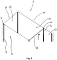
- Figure 1 shows a perspective view of a shower partition arrangement 1, which is connected to a room wall 11 and has at least one room partition segment 9.
- the shower partition arrangement 1 has a plurality of first profiles 3 which are arranged on a room wall 11 and are connected to one or more wall panels 13.
- FIG. 1 a transverse profile 7 can be seen, which is connected to a first profile 3 and the room dividing segment 9.
- Figure 2 shows a schematic detailed view of Figure 1 .
- FIG. 3 a perspective view of the first profile 3 and the second profile 5 can be seen.
- the first profile 3 and the second profile 5 are in contact with one another.
- the first profile 3 has a profiled side surface 35, which is connected to a room wall 11 and is in direct contact therewith by means of an adhesive connecting layer 31.
- An adhesive layer is preferably used as the adhesive connecting layer 31 of the room wall 11 with the first profile 3.
- the first profile 3 also has a groove 33 which is set up to accommodate a wall panel 13. The fixing of the wall panel 13 within the groove 33 of the first profile 3 also takes place by means of an adhesive connection layer 31, preferably glue.
- the first profile 3 can also be positioned behind a tile mirror and / or be in contact with it.
- the second profile 5 is arranged parallel to the first profile 3.
- the first profile 3 and the second profile 5 each have a side surface in contact with one another.
- the second profile 5 has, preferably opposite the side surface which is in contact with the first profile 3, a recess 37 which is designed to accommodate a room dividing segment 9.
- a bracing and sealing strip 39 is arranged within the recess 37.
- the bracing and sealing strip 39 is also designed to produce a seal in order to seal the interior of the second profile 5 against splashes of water.
- the bracing and sealing strip 39 is also known under the name of clamping strip with a sealing function.
- FIG. 11 shows a partially sectioned view of FIG Figure 1 respectively.
- Figure 3 A connection arrangement 15, which connects the first profile 3 and the second profile 5 to one another, can be seen.
- the connection arrangement 15 comprises a first clamping element 17 and a second clamping element 19.
- the first clamping element 17 can be introduced into the cavity 21 of the first profile 3 and is arranged in the cavity 21 in the assembled state.
- a corresponding second clamping element 19 can be introduced into the cavity 23 of the second profile 5 and, in the assembled state, is arranged in the cavity 23.
- Both clamping elements 17, 19 can be connected to one another by means of a threaded pin 27.
- the threaded pin 27 in a first exemplary embodiment is fixed in its position in the preassembled state with one of the clamping elements. This can be done, for example, by gluing.
- Figure 5 FIG. 11 shows a sectional view of FIG Figure 1 respectively.
- Figure 3 the threaded pin 27 is connected to the first clamping element 17 in the preassembled state. The first clamping element 17 is then inserted into the cavity 21 of the first profile 3 together with the threaded pin 27.
- the clamping element 17 is to be arranged in the groove-shaped recess 25 so that it cannot rotate, so that if the threaded pin 27 is screwed further to the first clamping element 17 until it hits the rear wall of the cavity 21, it is fixed in a selected position takes place along the groove-shaped recess 25.
- the second profile 5 is then arranged on the first profile 3.
- the second clamping element 19 is screwed onto the protruding end of the threaded pin 27 so that the first profile 3 is fixed with the second profile 5.
- the first clamping element 17 is designed in such a way that it has a clamping surface orthogonal to the effective direction of the clamping force, which is in contact with the inner side surface of the first profile 3.
- the first clamping element 17 has an essentially T-shaped shape, the legs forming a clamping surface.
- the first clamping element 17 tapers so that it can be introduced into the groove-shaped recess 25.
- This section of the first clamping element 17 has a shape such that, in the assembled state, it is arranged non-rotatably within the groove-shaped recess 25.
- Such a cross-sectional shape can be, for example, a rectangle, one side surface of which essentially corresponds to the width of the groove-shaped recess 25.
- the second clamping element 19 has an attachment element 47.
- the attachment element 47 is preferably formed from a plastic.
- the attachment element 47 is dimensioned such that it at least partially encases the second clamping element 19. It has at least one length that is greater than the side surface of the second clamping element 19, so that the attachment element 47 protrudes beyond the second clamping element 19 in the longitudinal direction. In this way, a protective effect is achieved which minimizes the risk of damage to the space dividing segment 9 during assembly, for example by impact against the second clamping element 19.
- Figure 6 shows a further variant of the shower cubicle arrangement 1.
- the first profile 3 is connected to a transverse profile 7.
- the first profile 3 is mounted on the room wall 11, in the same way as already to Figure 3 described.
- a wall panel 13 is connected to the first profile 3 on both sides.
- the first profile 3 comprises grooves 33 arranged on both sides for receiving the wall panels 13.
- the transverse profile 7 extends orthogonally to the first profile 3.
- the transverse profile 7 comprises a coupling piece 41 and a transverse profile rod 43.
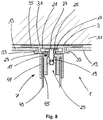
- Figure 7 shows a partially sectioned view and Figure 8 a sectional view of the Figure 6 .
- the connection arrangement 15 can be seen. This comprises the first clamping element 17 and the second clamping element 19, the second clamping element 19 being arranged in a cavity 23 of the transverse profile 7, in particular of the coupling piece 41.
- the transverse profile rod 43 is inserted into a groove 45 of the coupling piece 41 and fixed to the coupling piece 41 by means of a screw connection.
Landscapes
- Health & Medical Sciences (AREA)
- Public Health (AREA)
- Epidemiology (AREA)
- General Health & Medical Sciences (AREA)
- Residential Or Office Buildings (AREA)
Applications Claiming Priority (1)
| Application Number | Priority Date | Filing Date | Title |
|---|---|---|---|
| DE202020101316.5U DE202020101316U1 (de) | 2020-03-10 | 2020-03-10 | Duschabtrennungsanordnung |
Publications (1)
| Publication Number | Publication Date |
|---|---|
| EP3878331A1 true EP3878331A1 (fr) | 2021-09-15 |
Family
ID=74871166
Family Applications (1)
| Application Number | Title | Priority Date | Filing Date |
|---|---|---|---|
| EP21161769.1A Withdrawn EP3878331A1 (fr) | 2020-03-10 | 2021-03-10 | Agencement de paroi de douche |
Country Status (2)
| Country | Link |
|---|---|
| EP (1) | EP3878331A1 (fr) |
| DE (1) | DE202020101316U1 (fr) |
Citations (3)
| Publication number | Priority date | Publication date | Assignee | Title |
|---|---|---|---|---|
| EP0285914A2 (fr) * | 1987-04-07 | 1988-10-12 | Altura Leiden Holding B.V. | Séparation de douche |
| WO2001035806A1 (fr) * | 1999-11-18 | 2001-05-25 | Calibe S.R.L. | Appareil de douche |
| EP2382905A2 (fr) * | 2010-04-30 | 2011-11-02 | duka AG | Profilé creux |
Family Cites Families (5)
| Publication number | Priority date | Publication date | Assignee | Title |
|---|---|---|---|---|
| DE8624524U1 (de) | 1986-09-12 | 1986-10-30 | Hüppe GmbH, 2900 Oldenburg | Halterung einer Rahmenleiste in einer Wandleiste, insbesondere in Duschabtrennungen |
| DE10016354C2 (de) | 2000-04-03 | 2002-02-21 | Dorma Gmbh & Co Kg | Ausgleichselement zum Ausgleichen von Toleranzen zwischen einem Einsatzelement, wie Tür, Fenster o. dgl.,und einem Durchbruch |
| GB2504661A (en) | 2012-06-22 | 2014-02-12 | Aqualux Products Ltd | Improvements in or relating to adjustable mounting mechanisms |
| EP3251570A1 (fr) | 2016-05-31 | 2017-12-06 | Roth Werke GmbH | Dispositif de fixation et agrégat de douche |
| DE202018001036U1 (de) | 2018-02-27 | 2018-04-20 | Schulte Duschkabinenbau Gmbh & Co. Kg | Halteanordnung, Dichtungsanordnung und Duschabtrennung |
-
2020
- 2020-03-10 DE DE202020101316.5U patent/DE202020101316U1/de active Active
-
2021
- 2021-03-10 EP EP21161769.1A patent/EP3878331A1/fr not_active Withdrawn
Patent Citations (3)
| Publication number | Priority date | Publication date | Assignee | Title |
|---|---|---|---|---|
| EP0285914A2 (fr) * | 1987-04-07 | 1988-10-12 | Altura Leiden Holding B.V. | Séparation de douche |
| WO2001035806A1 (fr) * | 1999-11-18 | 2001-05-25 | Calibe S.R.L. | Appareil de douche |
| EP2382905A2 (fr) * | 2010-04-30 | 2011-11-02 | duka AG | Profilé creux |
Also Published As
| Publication number | Publication date |
|---|---|
| DE202020101316U1 (de) | 2021-07-07 |
Similar Documents
| Publication | Publication Date | Title |
|---|---|---|
| EP0334080B1 (fr) | Liaison en "T" entre deux profils, en particulier une traverse et un montant d'une façade | |
| EP0945577A2 (fr) | Dispositif de support d'encadrements pour portes ou fenêtres à la périphérie d'une ouverture de paroi | |
| DE19849152C2 (de) | Pfosten-Riegelverbindung | |
| DE102005044980B4 (de) | Stoßverbinder für Holz-/Aluminiumfassaden | |
| DE8632187U1 (de) | Vorrichtung zum Befestigen von Fasaden-Bauelementen (Fassadenelementen) an Konstruktionselementen | |
| EP0790363A2 (fr) | Système de façade pour couverture verticale, diagonale et horizontale | |
| AT522794B1 (de) | Adapter zur Halterung von Fassadenelementen | |
| DE3107725A1 (de) | Isolierende verbindungsvorrichtung fuer bauplatten, insbesondere glasscheiben tragende zweiteilige metallrahmen | |
| DE3442398C2 (fr) | ||
| EP3910155A1 (fr) | Dispositif de protection | |
| DE202020101316U1 (de) | Duschabtrennungsanordnung | |
| EP2186959B1 (fr) | Connexion en T entre un poteau profilé et une traverse profilée | |
| AT391513B (de) | Eckumlenkung fuer treibstangenbeschlaege | |
| DE3444801C2 (fr) | ||
| DE19617653C2 (de) | Verbindungsanordnung mit einem Profil | |
| EP1342861B1 (fr) | Dispositif de fixation | |
| DE102004022276B4 (de) | Vorrichtung zur Befestigung von Dämmstoffelementen an ebenen Flächen | |
| DE3147092C2 (de) | Verbindungssystem mit wenigstens einem Eckbogenelement | |
| DE10043444B4 (de) | Fenster- oder Türrahmen mit einem verschraubten Verbinder | |
| CH598448A5 (en) | Support structure for wall covering plates | |
| DE10229272A1 (de) | Stoßverbinder zum winkeligen Verbinden von Hohlprofilen | |
| DE10043443B4 (de) | Fenster- oder Türrahmen mit einem Verbinder | |
| DE102020106891B4 (de) | T-Verbindung zwischen einem Pfosten- und Riegelprofil und Pfosten-Riegel-Konstruktion mit einer derartigen T-Verbindung | |
| DE10044951C1 (de) | Sprossenverbindung für Glasdächer bzw. Glasfassaden | |
| EP3276100A1 (fr) | Système d'étanchéité pour un système de paroi |
Legal Events
| Date | Code | Title | Description |
|---|---|---|---|
| PUAI | Public reference made under article 153(3) epc to a published international application that has entered the european phase |
Free format text: ORIGINAL CODE: 0009012 |
|
| STAA | Information on the status of an ep patent application or granted ep patent |
Free format text: STATUS: THE APPLICATION HAS BEEN PUBLISHED |
|
| AK | Designated contracting states |
Kind code of ref document: A1 Designated state(s): AL AT BE BG CH CY CZ DE DK EE ES FI FR GB GR HR HU IE IS IT LI LT LU LV MC MK MT NL NO PL PT RO RS SE SI SK SM TR |
|
| STAA | Information on the status of an ep patent application or granted ep patent |
Free format text: STATUS: THE APPLICATION IS DEEMED TO BE WITHDRAWN |
|
| 18D | Application deemed to be withdrawn |
Effective date: 20220316 |