EP3878343A1 - Vorrichtung zur befestigung einer sockelleiste an einem eingebauten haushaltsgerät, insbesondere an einem eingebauten geschirrspüler - Google Patents
Vorrichtung zur befestigung einer sockelleiste an einem eingebauten haushaltsgerät, insbesondere an einem eingebauten geschirrspüler Download PDFInfo
- Publication number
- EP3878343A1 EP3878343A1 EP20163202.3A EP20163202A EP3878343A1 EP 3878343 A1 EP3878343 A1 EP 3878343A1 EP 20163202 A EP20163202 A EP 20163202A EP 3878343 A1 EP3878343 A1 EP 3878343A1
- Authority
- EP
- European Patent Office
- Prior art keywords
- positioner
- plinth
- holder
- dishwasher
- modular
- Prior art date
- Legal status (The legal status is an assumption and is not a legal conclusion. Google has not performed a legal analysis and makes no representation as to the accuracy of the status listed.)
- Withdrawn
Links
- 238000000034 method Methods 0.000 claims abstract description 35
- 238000005520 cutting process Methods 0.000 claims description 46
- 238000010168 coupling process Methods 0.000 description 5
- 238000005859 coupling reaction Methods 0.000 description 5
- 239000000463 material Substances 0.000 description 4
- 238000004873 anchoring Methods 0.000 description 3
- 238000004140 cleaning Methods 0.000 description 2
- 238000012423 maintenance Methods 0.000 description 2
- 238000013459 approach Methods 0.000 description 1
- 230000008878 coupling Effects 0.000 description 1
- 238000001035 drying Methods 0.000 description 1
- 238000009434 installation Methods 0.000 description 1
- 230000001788 irregular Effects 0.000 description 1
- 238000010412 laundry washing Methods 0.000 description 1
Images


Classifications
-
- D—TEXTILES; PAPER
- D06—TREATMENT OF TEXTILES OR THE LIKE; LAUNDERING; FLEXIBLE MATERIALS NOT OTHERWISE PROVIDED FOR
- D06F—LAUNDERING, DRYING, IRONING, PRESSING OR FOLDING TEXTILE ARTICLES
- D06F39/00—Details of washing machines not specific to a single type of machines covered by groups D06F9/00 - D06F27/00
- D06F39/12—Casings; Tubs
-
- A—HUMAN NECESSITIES
- A47—FURNITURE; DOMESTIC ARTICLES OR APPLIANCES; COFFEE MILLS; SPICE MILLS; SUCTION CLEANERS IN GENERAL
- A47L—DOMESTIC WASHING OR CLEANING; SUCTION CLEANERS IN GENERAL
- A47L15/00—Washing or rinsing machines for crockery or tableware
- A47L15/42—Details
- A47L15/4251—Details of the casing
-
- A—HUMAN NECESSITIES
- A47—FURNITURE; DOMESTIC ARTICLES OR APPLIANCES; COFFEE MILLS; SPICE MILLS; SUCTION CLEANERS IN GENERAL
- A47L—DOMESTIC WASHING OR CLEANING; SUCTION CLEANERS IN GENERAL
- A47L15/00—Washing or rinsing machines for crockery or tableware
- A47L15/0097—Combination of dishwashers with other household appliances
-
- A—HUMAN NECESSITIES
- A47—FURNITURE; DOMESTIC ARTICLES OR APPLIANCES; COFFEE MILLS; SPICE MILLS; SUCTION CLEANERS IN GENERAL
- A47L—DOMESTIC WASHING OR CLEANING; SUCTION CLEANERS IN GENERAL
- A47L15/00—Washing or rinsing machines for crockery or tableware
- A47L15/42—Details
- A47L15/4251—Details of the casing
- A47L15/4253—Supporting arrangements for the casing, e.g. rollers or supporting legs
-
- A—HUMAN NECESSITIES
- A47—FURNITURE; DOMESTIC ARTICLES OR APPLIANCES; COFFEE MILLS; SPICE MILLS; SUCTION CLEANERS IN GENERAL
- A47L—DOMESTIC WASHING OR CLEANING; SUCTION CLEANERS IN GENERAL
- A47L15/00—Washing or rinsing machines for crockery or tableware
- A47L15/42—Details
- A47L15/4251—Details of the casing
- A47L15/4257—Details of the loading door
- A47L15/4265—Arrangements of door covering/decoration panels or plinths, e.g. for integrated dishwashers
-
- A—HUMAN NECESSITIES
- A47—FURNITURE; DOMESTIC ARTICLES OR APPLIANCES; COFFEE MILLS; SPICE MILLS; SUCTION CLEANERS IN GENERAL
- A47B—TABLES; DESKS; OFFICE FURNITURE; CABINETS; DRAWERS; GENERAL DETAILS OF FURNITURE
- A47B95/00—Fittings for furniture
- A47B95/002—Plinths, e.g. between furniture and ceiling or wall
- A47B2095/004—Base plinths
Definitions
- the present invention relates to a device for fixing a plinth to a built-in household appliance, in particular to a built-in dishwasher.
- the present invention relates also to a method for fixing a plinth to a built-in household appliance, in particular to a built-in dishwasher.
- a built-in dishwasher is typically intended to be integrated in the furniture of a kitchen, more specifically in a dedicated space bordered above by the countertop of the integrated kitchen.
- the kitchen furniture generally has a front portion provided with a recessed lower part, at which a plinth is typically arranged to cover a respective recessed lower part of the dishwasher arranged therein.
- the recessed lower part of the kitchen furniture has a predefined depth, which may be different with respect to the recessed lower part of the dishwasher.
- a main aim of the present invention is to supply a device which is able to fix a plinth to a built-in household appliance, in particular to a built-in dishwasher in an easy and efficient way.
- a further aim of the present invention is to propose a device able to fix a plinth to a built-in household appliance, in particular to a built-in dishwasher in a secure and stable way.
- An additional aim of the present invention is to disclose a method for fixing a plinth to a built-in household appliance, in particular to a built-in dishwasher safely and firmly, the method allowing a particularly fine regulation of the distance between the plinth and the household appliance, so that the plinth fixed to the household appliance can be easily maintained flush with the plinths fixed to the pieces of furniture adjacent to the household appliance.
- a further aim of the present invention is to disclose a device and a method which are able to fix a plinth to a built-in household appliance, in particular to a built-in dishwasher in a plurality of different available space conditions.
- a 1st aspect relates to a device for fixing a plinth to a built-in household appliance, in particular to a built-in dishwasher comprising:
- the positioner is monolithic and the modular elements are connected to each other, the positioner being configured for being cut to allow the adjustment of its length.
- the positioner is configured for being cut at discrete locations thereby defining a plurality of discrete lengths.
- the positioner comprises a plurality of consecutive reference elements, such as ridges, each reference element defining a discrete location at or near which the positioner is configured for being cut at a predefined discrete length.
- the positioner comprises an external thread extending continuously along the main development direction, the positioner being configured for being cut at any location along the external thread.
- the holder is configured for being continuously moved along the external thread.
- the holder is configured for acting as cutting reference, in cutting conditions of the positioner the holder being positioned at a cutting location defined along the external thread, the portion of the positioner defined between an end of the positioner and a reference surface of the holder being the one to be cut away, the reference surface of the holder being destined to be fixed to the surface of the plinth facing, in use conditions of the device, the front portion of the dishwasher.
- the holder has an internal thread configured for interacting with the external thread of the positioner so as to continuously move the holder along the main development direction of the positioner.
- the holder has a rounded shape.
- the holder has a through-hole, at which the positioner is arranged in use conditions of the device, and a ring portion surrounding the through-hole, the ring portion being configured for being engaged to the surface of the plinth facing, in use conditions of the device, the front portion of the dishwasher.
- the holder comprises a neck portion extending transversally to the ring portion and having an axial extension which is greater than an axial extension of the ring portion, the neck portion being configured to be engaged to the positioner so as to move the holder along the main development direction.
- the neck portion is concentric to the ring portion.
- the modular elements are separate elements connectable to each other.
- each modular element comprises a seat and an engagement element defined on opposite sides of the modular element, the seat being configured for housing an engagement element of a first adjacent modular element and the engagement element being configured for engaging at a seat of a second adjacent modular element, the first adjacent modular element and the second adjacent modular element being opposite with respect to said modular element.
- the modular elements are configured to be interlocked so as to define a desired length of the positioner.
- the modular elements are configured to be detachably interlocked.
- the positioner comprises a first end and a second end opposite with respect to the main development direction, the holder comprising a housing configured for housing the first end of the positioner in use conditions of the device.
- the housing comprises a groove, in use conditions of the holder the groove being arranged vertically, the first end of the positioner being configured to slide along the groove.
- the first end of the positioner is at least partially countershaped to the groove.
- the holder comprises a plate configured for being engaged to said surface of the plinth by means of one or more screws.
- the plate comprises at least a through-hole or a plurality of through-holes, each through-hole being configured for housing a respective screw.
- the positioner comprises a first end and a second end opposite with respect to the main development direction, the device further comprising a constraint element configured for being engaged to a front portion of the dishwasher and for constraining the positioner to the front portion of the dishwasher, the constraint element being arranged or engaged at or near the second end of the positioner.
- the constraint element is configured for being engaged via snap-coupling to an engagement member arranged at the front portion of the dishwasher.
- the constraint element is configured for embracing an engagement member arranged at the front portion of the dishwasher.
- the constraint element is shaped as a collar.
- a 26th aspect relates to a method for fixing a plinth to a built-in dishwasher comprising the steps of:
- the step of adjusting a length of the positioner by connecting a plurality of modular elements comprises connecting, optionally interlocking, a plurality of separate modular elements.
- the positioner comprises an external thread extending continuously along the main development direction, the positioner being configured for being cut at any location along the external thread and the step of adjusting a length of the positioner by cutting away one or more modular elements or portions thereof comprising:
- positioning the holder at a cutting location defined along the external thread comprises rotating the holder along the external thread of the positioner.
- the step of engaging the device, at or near the first end of the positioner, to the plinth comprises the steps of:
- the holder comprising a housing configured for housing the first end of the positioner, the method comprising housing the first end of the positioner at the housing.
- the housing comprises a groove, for example a vertically arranged groove, the method comprising the step of vertically sliding the first end of the positioner along the groove.
- the holder comprises a plate
- the step of engaging the holder to the plinth comprises screwing the plate to said surface of the plinth.
- the holder comprises a ring portion
- the step of engaging the holder to the plinth comprises screwing the ring portion to said surface of the plinth.
- the method further comprises the steps of:
- the step of constraining the positioner to the front portion of the dishwasher by means of the constraint element comprises snap-coupling the constraint element to an engagement member arranged at the front portion of the dishwasher.
- the step of constraining the positioner to the front portion of the dishwasher by means of the constraint element comprises embracing, by means of the constraint element, an engagement member arranged at the front portion of the dishwasher.
- the step of adjusting the length of the positioner is performed before the step of engaging the device, optionally at or near the first end of the positioner, to the plinth.
- the step of engaging the device, optionally at or near the first end of the positioner, to the plinth is performed before the step of engaging the device, optionally at or near the second end of the positioner, to the front portion of the dishwasher.
- the step of engaging the device, optionally at or near the second end of the positioner, to the front portion of the dishwasher comprises approaching the plinth to the front portion of the dishwasher after having engaged the device to the plinth.
- the step of providing at least one device for fixing a plinth to a built-in dishwasher according to any one of the preceding aspects and/or to any one of the attached device claims comprises providing a first device and a second device.
- the step of engaging the device, at or near the first end of the positioner, to the plinth comprises engaging the first end of the positioner of the first device, for example by means of the holder of the first device, and the first end of the positioner of the second device, for example by means of the holder of the second device, at or near respective ends of the plinth, the ends of the plinth being opposite with respect to a longitudinal extension of the plinth.
- the step of engaging the device, at or near the second end of the positioner, to the front portion of the dishwasher comprises engaging the second end of the positioner of the first device, for example by means of a constraint element of the first device, and the second end of the positioner of the second device, for example by means of a constraint element of the second device, to a respective engagement member arranged at a front portion of the dishwasher.
- a 44th aspect relates to the use of a device according to any of the aspects from the 1st to the 25th and/or to any of the attached device claims for fixing a plinth to a built-in dishwasher.
- the use of the device comprises implementing the method according to any of the aspects from the 26th to the 43rd and/or to any of the attached method claims.
- the present invention is not limited to such a type of household appliance, but applies to any type of built-in household appliances, i.e. to any type of household appliances intended to be inserted in an integrated kitchen.
- the implementation of the invention on a built-in dishwasher hence represents only a preferred implementation.
- the invention in fact may be implemented on a built-in laundry washing machine, on a built-in laundry drying machine, on a built-in stove, on a built-in refrigerator, on a built-in freezer, and so on.
- the figures may illustrate the object of the invention, i.e. a device for fixing a plinth to a built-in dishwasher and a relative method for fixing a plinth to a built-in dishwasher, by means of representations not in scale; therefore, parts and components illustrated in the figures relating to the object of the invention may only concern schematic representations.
- the present invention relates to a device 1 for fixing a plinth 21 to a built-in dishwasher 100.
- the device 1 comprises a holder 2 and a positioner 3.
- the holder 2 and the positioner 3 are both preferably made of plastic material.
- the holder 2 is configured for being fixed to a surface 21a of the plinth 21 facing a front portion 100a of the dishwasher 100.
- the positioner 3 is connectable to the dishwasher 100 and to the holder 2 and is configured for being coupled to the plinth 21 by means of the holder 2.
- the positioner 3 has a certain length L.
- the positioner 3 is configured for being engaged, at respective portions thereof, to a surface 21a of the plinth 21 facing the dishwasher 100 and to the front portion 100a of the dishwasher 100.
- the positioner 3 comprises a plurality of modular elements 4 which are connected or connectable to each other.
- the length of the positioner 3 is configured to be adjusted by managing the connection between the modular elements.
- the length L of the positioner 3 is adjusted, according to the invention, so as to allow the device 1 to cover, in use conditions, a distance D, which is the distance intended to be established between the plinth 21 and an engagement member 101 of the dishwasher 100 arranged at the front portion 100a thereof (see left side of figure 2 ). By covering that distance D, the device 1 allows the desired positioning of the plinth with respect to the dishwasher 100.
- the positioner 3 in its basic configuration (see figure 1 and figure 6 ) or in its assembled configuration (see figure 10 , wherein a positioner 3 is being assembled), extends along a main development direction MD between a first end 3a and a second end 3b.
- the first end 3a and the second end 3b of the positioner 3 are opposite with respect to the main development direction MD.
- the device 1 further comprises a constraint element 5, which is arranged at the second end 3b of the positioner 3 and is opposite to the holder 2.
- the constraint element 5 is configured for being engaged to the engagement member 101 arranged at the front portion 100a of the dishwasher 100.
- the distance D may be defined between the surface 21a of the plinth 21 arranged at the desired fixing location and a front surface of the engagement member 101.
- the engagement member 101 can be a leg of the dishwasher 100 having a substantially cylindrical portion embraceable by the constraint element 5.
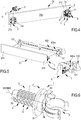
- FIGS. 1 to 5 show a device 1 according to the first embodiment of the invention, which is described in the following paragraphs.
- the positioner 3 is monolithic and, hence, modular elements 4 of the positioner are firmly connected to each other.
- the succession of modular elements 4 is clearly shown in the side view of the device 1 as illustrated on the right side of figure 2 .
- the positioner 3 of the device 1 according to the first embodiment of the invention is configured to be cut at a discrete location, defined along the length L of the positioner 3, in order to adjust its length L to the distance D between the plinth 21 and the front portion 100a of the dishwasher 100.
- figure 2 which, on its right side, schematically shows a cutting operation of the positioner 3.
- Each modular element 4 comprises a reference element 4a which is aimed at allowing the positioner to be cut at discrete locations.
- each reference element comprises a ridge 4a and a recessed portion 4b, which is defined between each couple of consecutive ridges 4a.
- the cutting operation of the positioner 3 may be performed at a determined recessed portion 4b, which defines a discrete location corresponding to the desired positioner distance D to be covered.
- the pitch between the ridges 4a is as thin as possible compatibly with the need of ensuring a proper stiffness to the positioner 3.
- the pitch between the ridges 4a is equal to or lower than 4 mm. More preferably, the pitch between the ridges 4a is equal to or lower than 2,5 mm.
- the constraint element 5 is arranged at the second end 3b of the positioner 3.
- the constraint element 5 is configured for being engaged to the engagement member 101 arranged at the front portion 100a of the dishwasher 100 and hence for constraining the positioner 3 to the front portion 100a of the dishwasher 100 (see figure 5 and its detail).
- the constraint element 5 may be configured for being engaged via snap-coupling to the engagement member 101. According to possible variants of the present embodiment, the constraint element 5 may be engaged to the engagement member 101 in alternative ways.
- the constraint element 5 may have a collar shape configured for allowing it to embrace the engagement member 101, thereby allowing an engagement between them which is at the same time stable (so ensuring a firm support of the plinth) and comfortable to be released (so allowing an easy and quick removal of the plinth, e.g. for cleaning and maintenance operations).
- the constraint element 5 advantageously comprises two elastic flaps for a snap engagement on the engagement member 101.
- the holder is basically a plate 2.
- the plate 2 comprises a housing configured for housing the first end 3a of the positioner 3 in use conditions of the device 1.
- the housing is basically a groove 2a along which the first end 3a of the positioner 3 is configured to slide to reach a desired vertical position and hence a desired height at which the positioner 3 is to be installed.
- the groove 2a is arranged vertically (see the right side of figure 1 ) and hence the first end 3a of the positioner 3 may slide vertically along the groove 2a.
- the first end 3a of the positioner 3 may be at least partially countershaped to the groove 2a.
- the holder 2 comprises anchoring means allowing the holder 2 to be fastened to the plinth 1.
- anchoring means comprise a plurality of bores 2b configured for housing a respective screw 6 allowing the holder to be engaged to the plinth 21 (see figure 3 ).
- Such a configuration of the holder is particularly recommended when the plinth is a wooden element.
- the first embodiment is particularly advantageous in that, by cutting the positioner 3 at discrete cutting locations along the main development direction MD, the cutting operation is easy and fast to perform as there are reference elements 4a indicating the possible cutting locations.
- Figures from 6 to 9 show a device according to a second embodiment of the invention.
- the positioner 3 of the device 1 according to the second embodiment of the invention is monolithic and is configured for being cut in order to adjust its length L according to the distance D intended to be established between the plinth 21 and the front portion 100a of the dishwasher 100.
- the positioner 3 of the device 1 according to the second embodiment of the invention may be cut at any location along its length L.
- the device 1 according to the second embodiment may be basically of a universal type, allowing the device 1 to be fixed to any distance D defined between the plinth 21 and the front portion 100a of the dishwasher 100 and comprised between a fraction of the length L of the positioner 3 (fraction of length L obtainable by cutting the positioner 3) and the entire length L of the positioner 3 (no need to cut the positioner 3).
- the positioner 3 comprises an external thread 7 extending continuously along the main development direction MD and has, at least partially, a rotational symmetry.
- the main development direction MD of the positioner may be defined by a main development axis MA.
- the modular element 4 of the device 1 according to the second embodiment may be represented by a complete rotation (twist) of the external thread 7 about the main development axis.
- the positioner 3 is configured for being cut at any location along the external thread 7. The cutting operation of the positioner 3 will be described in greater detail in the following paragraphs.
- the constraint element 5 of the device 1 is arranged at the second end 3b of the positioner. As shown in figures from 6 to 9, the constraint element 5 of the device 1 according to the second embodiment of the invention may have the same features as the constraint element 5 of the device 1 according to the first embodiment.
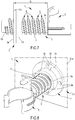
- the holder 2 is configured for being continuously moved along the external thread 7 - in that regard, see figure 6 and 7 .
- the continuous movement of the holder 2 along the positioner 3 is possible as the holder 2 has an internal thread configured for interacting with the external thread 7 of the positioner 3.
- the holder 2 has a through-hole and a ring portion 2c surrounding the through-hole.
- the through-hole basically coincides with the housing 2a.
- the ring portion 2c has a determined axial extension and is configured for being abutted and engaged to the surface 21a of the plinth 21 facing, in use conditions of the device 1, the front portion 100a of the dishwasher 100 (see figure 8 ).
- the positioner 3 is arranged at the through-hole.
- the ring portion 2c has advantageously a plurality of bores 2b aimed at allowing the engagement of the holder 2 to the plinth 21 by means of respective screws 6.
- the holder 2 may comprise also a neck portion 2d concentric to the ring portion 2c and extending transversally to the ring portion 2c.
- the neck portion 2d has an axial extension which is greater than the axial extension of the ring portion 2c.
- the neck portion 2d is configured to be engaged to the positioner 3 so as to move the holder 2 along the main development axis MA.
- the internal thread of the holder 2 may be defined at least at an internal surface of the neck portion 2d.
- the holder 2 is configured for acting as cutting reference able to allow cutting the positioner 3 at any desired length defined along the external thread 7 of the positioner 3. In cutting conditions of the positioner, the holder 2 is positioned at a cutting location defined along the external thread 7 (see figure 7 ).
- the portion of the positioner 3 defined between the first end 3a of the positioner 3 and a reference surface 2e of the holder 2 is the one to be cut away - in that regard, see figure 7 , where the reference surface 2e of the holder 2 is the left one and the portion to be cut away is the one defined on the left side of figure 7 beyond the reference surface 2e of the holder 2.
- the reference surface 2e of the holder 2 is destined to be abutted and fixed to the surface 21a of the plinth 21 facing, in use conditions of the device 1, the front portion 100a of the dishwasher 100.
- the second embodiment is particularly advantageous in that, by cutting the positioner 3 at any position along the main development axis MA, it is possible to reach any desired length L of the positioner 3 and hence any desired distance D to be covered by the device 1.
- the second embodiment allows a continuous regulation of the length of the positioner 3 and consequently a finer adjustment of the distance between the plinth 21 and the dishwasher 100.
- Figure 10 shows the positioner 3 of a device 1 according to a third embodiment of the invention.
- the modular elements 4 are separate elements of the positioner 3 connectable to each other.
- the modular elements 4 are advantageously made of plastic material.
- the modular elements 4 are in assembled configuration.
- the assembled configuration of the modular elements 4 see figure 10 showing a final operation of an assembling step of the positioner 3.
- each modular element 4 comprises a seat 4c and an engagement element 4d defined on opposite sides of the modular element 4.
- the seat 4c of a modular element 4 (as the one shown in exploded configuration in figure 10 ) is configured for housing an engagement element 4d of a first adjacent modular element 4 (as the one on the left of the one shown in exploded configuration in figure 10 ) and the engagement element 4d of the same modular element 4 is configured for engaging at a seat 4c of a second adjacent modular element 4 (as the one on the right of the one shown in exploded configuration in figure 10 ).
- the first adjacent modular element 4 and the second adjacent modular element 4 are opposite with respect to said modular element 4.
- the seat 4c is defined by a recessed portion of the modular element 4 while the engagement element 4d is a projecting portion of the modular element 4.
- each seat 4c is basically defined by a T-shaped recessed volume and each engagement element 4d is basically defined by a T-shaped projection.
- the seats 4c and the engagement elements 4d may have a different shapes with respect to the ones depicted in figure 10 .
- the modular elements 4 may be substantially equal in length. Alternatively, the modular elements 4 may have at least two distinct lengths: in such a situation, the longer modular elements may be used for a faster assembling of the positioner 3 at the side adjacent to the dishwasher base 100a and the shorter modular elements may be used instead for a fine regulation of the distance D at the side adjacent to the plinth 21.
- the constraint element 5 of the device 1 according to the third embodiment has a configuration analogous to the configuration of the constraint element 5 according to the first embodiment and is associated to a modular element positioned at one end of the positioner 3, such modular end comprising an engagement element 4d configured to be housed in the seat 4c of the adjacent modular element 4.
- the holder 2 of the device 1 according to the third embodiment of the invention may have the same features of the holder 2 of the device 1 according to the first embodiment.
- the third embodiment is particularly advantageous in that, by assembling the exact number of modular elements 4 needed to reach the desired length of the positioner 3 and hence the desired distance D to be covered by the device, there is no wastage of material.
- two devices 1 in order to engage the plinth 21 to the dishwasher 100, two devices 1 according to the invention may be needed.
- FIGS 3-5 showing two holders 2, each of which may be engaged at or near a respective portion 21b, 21c of the plinth 21 defined along a longitudinal extension of the plinth 21 (see figure 3 ) and each of which is configured to engage a respective positioner 3 at its first end (see figure 4 ).
- the distance between the positioners 3 is equal or corresponds to the distance between the respective engagement members 101 to which the constraint element 5 of each device 1 is configured to be engaged. That way, a stable and symmetric engagement between the front portion 100a of the dishwasher 100 and the plinth 21 is possible.
- the invention also relates to a method for fixing a plinth 21 to a built-in dishwasher 100.
- the method makes use of at least one device 1 of the above described type and of a plinth 21.
- the method provides for adjusting a length L of the positioner 3.
- the step of adjusting the length L of the positioner 3 is performed by connecting one or more modular elements 4 or by cutting away one or more modular elements 4 or portions thereof.
- the step of cutting away one or more modular elements 4 or portions thereof is preferably performed on a device 1 according to the above described first embodiment or second embodiment.
- the step of cutting away one or more modular elements 4 or portions thereof is performed as described above, i.e. by cutting the positioner 3 at a discrete location at or near reference elements such as ridges, in particular at a recessed portion defined between consecutive ridges. Cutting the positioner 3 at a discrete location allows to reach a discrete length of the positioner 3, corresponding to a specific distance D to be covered (see right side of figure 2 ).
- the cutting step is performed by continuously moving the holder 2 along the external thread 7 of the positioner 3 as described above. Once the holder 2 has been positioned at the cutting location defined along the external thread 7, the cutting step is performed by cutting away the portion of the positioner 3 defined between the first end 3a of the positioner 3 and the reference surface 2e of the holder 2 (see figure 7 ).
- the cutting step may be performed by any cutting means or cutting tool suitable for cutting the material which the positioner is made of.
- the step of adjusting a length L of the positioner 3 is performed by connecting a plurality of modular elements 4.
- a modular element 4 which is in exploded configuration with respect to consecutive modular elements 4 (the one on the right and the one on the left with respect to it) to which it is to be connected.
- the method includes engaging the device 1 to the plinth 21.
- the engagement of the device 1 to the plinth 21 is performed by engaging the first end 3a of the positioner 3 to the holder 2 (see figure 4 ), which has been previously engaged to the plinth 21, thereby allowing fixing of the device 1 to the plinth 21.
- the engagement of the holder 2 to the plinth 21 is schematically shown in figure 3 - as described above, the engagement of the holder 2 to the plinth 21 may be performed by means of a plurality of screws 6.
- the step of adjusting the length L of the positioner 3 is performed before engaging the device 1 to the plinth 21.
- the method includes also engaging the device 1 to the front portion 100a of the dishwasher 100.
- the step of engaging the device 1 to the front portion 100a of the dishwasher 100 is performed after having engaged the device 1 to the plinth 21.
- the engagement of the device 1 to the front portion 100a of the dishwasher 100 is performed by engaging the constraint element 5, which is arranged near the second end 3b of the positioner 3, to the engagement member 101 arranged at the front portion 100a of the dishwasher 100.
- the step of engaging the device 1 to the front portion 100a of the dishwasher 100 is performed by constraining the positioner 3 to the engagement member 101 by means of the constraint element 5.
- Constraining the positioner 3 to the engagement member 101 may be performed by snap-coupling the constraint element 5 to the engagement member 101. Constraining the positioner 3 to the engagement member 101 is performed by embracing, by means of the constraint element 5 (intentionally shaped like a collar), the engagement member 101. The result of that step is that the positioner 3 is constrained and hence engaged near its second end 3b to the front portion 100a of the dishwasher 100.
- the device 1 is arranged, with respect to the built-in dishwasher 100 and to the plinth 21, so that the first end 3a of the positioner 3 is near and faces the plinth 21 and the second end 3b of the positioner is near and faces the front portion 100a of the dishwasher 100 (see the detail of figure 5 and figure 9 ).
- the method may provide fixing two devices 1 to a single plinth 21 and to a respective part of the front portion 100a of the dishwasher 100. Fixing two devices 1 to a single plinth 21 may be performed according to what has been described above, taking into account that each holder 2 of each of the two devices 1 may be engaged at or near a respective end 21b, 21c of the plinth 21 defined along a longitudinal extension of the plinth 21 (see figure 3 ).
- the invention is capable to provide a device for fixing a plinth to a built-in household appliance, in particular to a built-in dishwasher, wherein the configuration of the positioner allows the plinth to be installed at the proper distance from the dishwasher, since the positioner is in essence a body whose length may be adapted depending on the desired position of the plinth relatively to the dishwasher. Moreover, the removable connection between the holder and the positioner allows a precise installation of the plinth and furthermore allows the plinth to be easily detached from the dishwasher, e.g. for cleaning and maintenance operations.
- the invention is able to obtain at least the further following relevant advantages.
- the device 1 and the method according to the invention allow fixing a plinth 21 to a built-in dishwasher 100 in a fast and efficient way. This is possible by cutting one or more modular elements 4 or portions thereof of a monolithic positioner 3 (first and second embodiments) or connecting separate modular elements 4 of a positioner 3 (third embodiment).
- the device 1 and the method according to the invention make it possible an easy regulation of the horizontal and vertical position of the device 1 and a continuous vertical positioning of the plinth 21.
Landscapes
- Engineering & Computer Science (AREA)
- Textile Engineering (AREA)
- Washing And Drying Of Tableware (AREA)
Priority Applications (2)
| Application Number | Priority Date | Filing Date | Title |
|---|---|---|---|
| EP20163202.3A EP3878343A1 (de) | 2020-03-13 | 2020-03-13 | Vorrichtung zur befestigung einer sockelleiste an einem eingebauten haushaltsgerät, insbesondere an einem eingebauten geschirrspüler |
| CN202110269656.3A CN113384213A (zh) | 2020-03-13 | 2021-03-12 | 将踢脚固定至嵌入式家用电器、特别是嵌入式洗碗机的装置 |
Applications Claiming Priority (1)
| Application Number | Priority Date | Filing Date | Title |
|---|---|---|---|
| EP20163202.3A EP3878343A1 (de) | 2020-03-13 | 2020-03-13 | Vorrichtung zur befestigung einer sockelleiste an einem eingebauten haushaltsgerät, insbesondere an einem eingebauten geschirrspüler |
Publications (1)
| Publication Number | Publication Date |
|---|---|
| EP3878343A1 true EP3878343A1 (de) | 2021-09-15 |
Family
ID=69844611
Family Applications (1)
| Application Number | Title | Priority Date | Filing Date |
|---|---|---|---|
| EP20163202.3A Withdrawn EP3878343A1 (de) | 2020-03-13 | 2020-03-13 | Vorrichtung zur befestigung einer sockelleiste an einem eingebauten haushaltsgerät, insbesondere an einem eingebauten geschirrspüler |
Country Status (2)
| Country | Link |
|---|---|
| EP (1) | EP3878343A1 (de) |
| CN (1) | CN113384213A (de) |
Cited By (2)
| Publication number | Priority date | Publication date | Assignee | Title |
|---|---|---|---|---|
| CN116828339A (zh) * | 2023-08-28 | 2023-09-29 | 合肥岭雁科技有限公司 | 一种便于安装的家庭网关 |
| WO2024025427A1 (en) * | 2022-07-29 | 2024-02-01 | Fisher & Paykel Appliances Limited | Toe-kick plate attachment system for appliance |
Citations (3)
| Publication number | Priority date | Publication date | Assignee | Title |
|---|---|---|---|---|
| DE19804897A1 (de) * | 1998-02-07 | 1999-08-12 | Aeg Hausgeraete Gmbh | Hausgerät mit einem Gehäusesockelbereich und einer am Gehäusesockelbereich befestigbaren Sockelleiste |
| EP1362530A1 (de) * | 2002-05-17 | 2003-11-19 | SCILM S.p.A. | Vorrichtung zur Kopplung der Fussleiste eines Möbelstücks am Fuss dieses Möbelstücks |
| EP2786692B1 (de) | 2013-04-05 | 2016-06-08 | Indesit Company S.p.A. | Vorrichtung zur Befestigung einer Sockelblende an einem Haushaltgerät |
-
2020
- 2020-03-13 EP EP20163202.3A patent/EP3878343A1/de not_active Withdrawn
-
2021
- 2021-03-12 CN CN202110269656.3A patent/CN113384213A/zh active Pending
Patent Citations (3)
| Publication number | Priority date | Publication date | Assignee | Title |
|---|---|---|---|---|
| DE19804897A1 (de) * | 1998-02-07 | 1999-08-12 | Aeg Hausgeraete Gmbh | Hausgerät mit einem Gehäusesockelbereich und einer am Gehäusesockelbereich befestigbaren Sockelleiste |
| EP1362530A1 (de) * | 2002-05-17 | 2003-11-19 | SCILM S.p.A. | Vorrichtung zur Kopplung der Fussleiste eines Möbelstücks am Fuss dieses Möbelstücks |
| EP2786692B1 (de) | 2013-04-05 | 2016-06-08 | Indesit Company S.p.A. | Vorrichtung zur Befestigung einer Sockelblende an einem Haushaltgerät |
Non-Patent Citations (1)
| Title |
|---|
| S GÖTEBORG PLADS: "ETA-Danmark A", 24 April 2017 (2017-04-24), XP055712027, Retrieved from the Internet <URL:https://eshop.wuerth.de/is-bin/INTERSHOP.enfinity/WFS/1401-B1-Site/de_DE/-/EUR/ViewOfferDetail-GetDocument/0681492001ZZL05.pdf?ProductRefID=0681492001@1401-B1&DocumentId=D69B0B8F40021ED78BF99B83454F8ACD&MimeType=application/pdf> [retrieved on 20200706] * |
Cited By (3)
| Publication number | Priority date | Publication date | Assignee | Title |
|---|---|---|---|---|
| WO2024025427A1 (en) * | 2022-07-29 | 2024-02-01 | Fisher & Paykel Appliances Limited | Toe-kick plate attachment system for appliance |
| CN116828339A (zh) * | 2023-08-28 | 2023-09-29 | 合肥岭雁科技有限公司 | 一种便于安装的家庭网关 |
| CN116828339B (zh) * | 2023-08-28 | 2023-10-31 | 合肥岭雁科技有限公司 | 一种便于安装的家庭网关 |
Also Published As
| Publication number | Publication date |
|---|---|
| CN113384213A (zh) | 2021-09-14 |
Similar Documents
| Publication | Publication Date | Title |
|---|---|---|
| KR102770075B1 (ko) | 가구 또는 가전 제품용 보관 선반 베이스 | |
| AU2006331388B2 (en) | Quick-fixing element | |
| US9486069B2 (en) | Vibration-damped furniture piece in the form of a table | |
| US8091489B2 (en) | Connecting device for furniture | |
| MXPA02004801A (es) | Unidad para el montaje de un accesorio electrico. | |
| EP2476340B1 (de) | Vorrichtung zur Höheneinstellung von Schubladen | |
| MX2012012391A (es) | Mecanismo de deslizamiento mejorado para gaveta. | |
| JP2011078758A (ja) | ロック構成 | |
| EP2786692A1 (de) | Vorrichtung zur Befestigung einer Sockelblende an einem Haushaltgerät | |
| EP2752526A2 (de) | Vorrichtung zur Wandmontage einer Installationsstruktur für eine Sanitäranlagenbefestigung | |
| EP2146615B1 (de) | Einbausystem für eine geschirrspülmaschine und zugeordnetes verfahren | |
| US6733098B1 (en) | Bracket and method for converting side mount drawer to under mount drawer | |
| KR102701776B1 (ko) | 가구 또는 가전 제품 및 가구 또는 가전 제품에 서랍 요소의 기능 유닛을 장착하는 방법 | |
| CN113384213A (zh) | 将踢脚固定至嵌入式家用电器、特别是嵌入式洗碗机的装置 | |
| CN105003466A (zh) | 风扇固定装置 | |
| JP5310025B2 (ja) | 壁付水栓及びその取り付け方法 | |
| WO2011034574A2 (en) | Adjustable countertop mounting system | |
| EP4610562A1 (de) | Montagering und system für eine einbauleuchte | |
| KR20090008424U (ko) | 주방 가구용 다리 | |
| JP4491467B2 (ja) | アジャスタ取付構造 | |
| KR200351036Y1 (ko) | 수납선반용 신축지지봉 | |
| WO2021001447A1 (en) | Profile fixing accessory and support system comprising such profile fixing accessory for cladding, elevated floors, lowered ceilings or such | |
| JP2008154630A (ja) | 家具転倒防止具及び建物 | |
| CN222955109U (zh) | 用于家用电器的固定件、定位件和家用电器 | |
| KR200167011Y1 (ko) | 화장실칸막이 고정받침대 |
Legal Events
| Date | Code | Title | Description |
|---|---|---|---|
| PUAI | Public reference made under article 153(3) epc to a published international application that has entered the european phase |
Free format text: ORIGINAL CODE: 0009012 |
|
| STAA | Information on the status of an ep patent application or granted ep patent |
Free format text: STATUS: THE APPLICATION HAS BEEN PUBLISHED |
|
| AK | Designated contracting states |
Kind code of ref document: A1 Designated state(s): AL AT BE BG CH CY CZ DE DK EE ES FI FR GB GR HR HU IE IS IT LI LT LU LV MC MK MT NL NO PL PT RO RS SE SI SK SM TR |
|
| STAA | Information on the status of an ep patent application or granted ep patent |
Free format text: STATUS: REQUEST FOR EXAMINATION WAS MADE |
|
| STAA | Information on the status of an ep patent application or granted ep patent |
Free format text: STATUS: THE APPLICATION IS DEEMED TO BE WITHDRAWN |
|
| 17P | Request for examination filed |
Effective date: 20220314 |
|
| RBV | Designated contracting states (corrected) |
Designated state(s): AL AT BE BG CH CY CZ DE DK EE ES FI FR GB GR HR HU IE IS IT LI LT LU LV MC MK MT NL NO PL PT RO RS SE SI SK SM TR |
|
| 18D | Application deemed to be withdrawn |
Effective date: 20220316 |