EP3878488B1 - Blutreinigungsapparat - Google Patents
Blutreinigungsapparat Download PDFInfo
- Publication number
- EP3878488B1 EP3878488B1 EP19902995.0A EP19902995A EP3878488B1 EP 3878488 B1 EP3878488 B1 EP 3878488B1 EP 19902995 A EP19902995 A EP 19902995A EP 3878488 B1 EP3878488 B1 EP 3878488B1
- Authority
- EP
- European Patent Office
- Prior art keywords
- pump
- pump tube
- peristaltic
- purification apparatus
- blood purification
- Prior art date
- Legal status (The legal status is an assumption and is not a legal conclusion. Google has not performed a legal analysis and makes no representation as to the accuracy of the status listed.)
- Active
Links
Images






Classifications
-
- A—HUMAN NECESSITIES
- A61—MEDICAL OR VETERINARY SCIENCE; HYGIENE
- A61M—DEVICES FOR INTRODUCING MEDIA INTO, OR ONTO, THE BODY; DEVICES FOR TRANSDUCING BODY MEDIA OR FOR TAKING MEDIA FROM THE BODY; DEVICES FOR PRODUCING OR ENDING SLEEP OR STUPOR
- A61M1/00—Suction or pumping devices for medical purposes; Devices for carrying-off, for treatment of, or for carrying-over, body-liquids; Drainage systems
- A61M1/36—Other treatment of blood in a by-pass of the natural circulatory system, e.g. temperature adaptation, irradiation ; Extra-corporeal blood circuits
- A61M1/3621—Extra-corporeal blood circuits
- A61M1/367—Circuit parts not covered by the preceding subgroups of group A61M1/3621
-
- A—HUMAN NECESSITIES
- A61—MEDICAL OR VETERINARY SCIENCE; HYGIENE
- A61M—DEVICES FOR INTRODUCING MEDIA INTO, OR ONTO, THE BODY; DEVICES FOR TRANSDUCING BODY MEDIA OR FOR TAKING MEDIA FROM THE BODY; DEVICES FOR PRODUCING OR ENDING SLEEP OR STUPOR
- A61M1/00—Suction or pumping devices for medical purposes; Devices for carrying-off, for treatment of, or for carrying-over, body-liquids; Drainage systems
- A61M1/14—Dialysis systems; Artificial kidneys; Blood oxygenators ; Reciprocating systems for treatment of body fluids, e.g. single needle systems for hemofiltration or pheresis
- A61M1/16—Dialysis systems; Artificial kidneys; Blood oxygenators ; Reciprocating systems for treatment of body fluids, e.g. single needle systems for hemofiltration or pheresis with membranes
- A61M1/1601—Control or regulation
-
- A—HUMAN NECESSITIES
- A61—MEDICAL OR VETERINARY SCIENCE; HYGIENE
- A61M—DEVICES FOR INTRODUCING MEDIA INTO, OR ONTO, THE BODY; DEVICES FOR TRANSDUCING BODY MEDIA OR FOR TAKING MEDIA FROM THE BODY; DEVICES FOR PRODUCING OR ENDING SLEEP OR STUPOR
- A61M60/00—Blood pumps; Devices for mechanical circulatory actuation; Balloon pumps for circulatory assistance
- A61M60/10—Location thereof with respect to the patient's body
- A61M60/104—Extracorporeal pumps, i.e. the blood being pumped outside the patient's body
- A61M60/109—Extracorporeal pumps, i.e. the blood being pumped outside the patient's body incorporated within extracorporeal blood circuits or systems
- A61M60/113—Extracorporeal pumps, i.e. the blood being pumped outside the patient's body incorporated within extracorporeal blood circuits or systems in other functional devices, e.g. dialysers or heart-lung machines
-
- A—HUMAN NECESSITIES
- A61—MEDICAL OR VETERINARY SCIENCE; HYGIENE
- A61M—DEVICES FOR INTRODUCING MEDIA INTO, OR ONTO, THE BODY; DEVICES FOR TRANSDUCING BODY MEDIA OR FOR TAKING MEDIA FROM THE BODY; DEVICES FOR PRODUCING OR ENDING SLEEP OR STUPOR
- A61M60/00—Blood pumps; Devices for mechanical circulatory actuation; Balloon pumps for circulatory assistance
- A61M60/20—Type thereof
- A61M60/247—Positive displacement blood pumps
- A61M60/253—Positive displacement blood pumps including a displacement member directly acting on the blood
- A61M60/268—Positive displacement blood pumps including a displacement member directly acting on the blood the displacement member being flexible, e.g. membranes, diaphragms or bladders
- A61M60/279—Peristaltic pumps, e.g. roller pumps
-
- A—HUMAN NECESSITIES
- A61—MEDICAL OR VETERINARY SCIENCE; HYGIENE
- A61M—DEVICES FOR INTRODUCING MEDIA INTO, OR ONTO, THE BODY; DEVICES FOR TRANSDUCING BODY MEDIA OR FOR TAKING MEDIA FROM THE BODY; DEVICES FOR PRODUCING OR ENDING SLEEP OR STUPOR
- A61M60/00—Blood pumps; Devices for mechanical circulatory actuation; Balloon pumps for circulatory assistance
- A61M60/30—Medical purposes thereof other than the enhancement of the cardiac output
- A61M60/36—Medical purposes thereof other than the enhancement of the cardiac output for specific blood treatment; for specific therapy
- A61M60/37—Haemodialysis, haemofiltration or diafiltration
-
- A—HUMAN NECESSITIES
- A61—MEDICAL OR VETERINARY SCIENCE; HYGIENE
- A61M—DEVICES FOR INTRODUCING MEDIA INTO, OR ONTO, THE BODY; DEVICES FOR TRANSDUCING BODY MEDIA OR FOR TAKING MEDIA FROM THE BODY; DEVICES FOR PRODUCING OR ENDING SLEEP OR STUPOR
- A61M60/00—Blood pumps; Devices for mechanical circulatory actuation; Balloon pumps for circulatory assistance
- A61M60/40—Details relating to driving
- A61M60/424—Details relating to driving for positive displacement blood pumps
- A61M60/457—Details relating to driving for positive displacement blood pumps the force acting on the blood contacting member being magnetic
- A61M60/462—Electromagnetic force
-
- A—HUMAN NECESSITIES
- A61—MEDICAL OR VETERINARY SCIENCE; HYGIENE
- A61M—DEVICES FOR INTRODUCING MEDIA INTO, OR ONTO, THE BODY; DEVICES FOR TRANSDUCING BODY MEDIA OR FOR TAKING MEDIA FROM THE BODY; DEVICES FOR PRODUCING OR ENDING SLEEP OR STUPOR
- A61M60/00—Blood pumps; Devices for mechanical circulatory actuation; Balloon pumps for circulatory assistance
- A61M60/80—Constructional details other than related to driving
- A61M60/835—Constructional details other than related to driving of positive displacement blood pumps
-
- A—HUMAN NECESSITIES
- A61—MEDICAL OR VETERINARY SCIENCE; HYGIENE
- A61M—DEVICES FOR INTRODUCING MEDIA INTO, OR ONTO, THE BODY; DEVICES FOR TRANSDUCING BODY MEDIA OR FOR TAKING MEDIA FROM THE BODY; DEVICES FOR PRODUCING OR ENDING SLEEP OR STUPOR
- A61M2205/00—General characteristics of the apparatus
- A61M2205/14—Detection of the presence or absence of a tube, a connector or a container in an apparatus
-
- A—HUMAN NECESSITIES
- A61—MEDICAL OR VETERINARY SCIENCE; HYGIENE
- A61M—DEVICES FOR INTRODUCING MEDIA INTO, OR ONTO, THE BODY; DEVICES FOR TRANSDUCING BODY MEDIA OR FOR TAKING MEDIA FROM THE BODY; DEVICES FOR PRODUCING OR ENDING SLEEP OR STUPOR
- A61M2205/00—General characteristics of the apparatus
- A61M2205/60—General characteristics of the apparatus with identification means
- A61M2205/6018—General characteristics of the apparatus with identification means providing set-up signals for the apparatus configuration
Definitions
- Some of blood purification apparatuses each include a plurality of peristaltic pumps for delivering liquids such as substitution fluid and drain liquid.
- the peristaltic pumps are provided with pump tubes, respectively, so that different liquids can be delivered.
- an attaching member has been disclosed by PTL 1 that includes a plurality of pump tubes attachable to respective peristaltic pumps included in a blood purification apparatus. The attaching member is to be attached to a predetermined position of the blood purification apparatus.
- a blood purification apparatus including the following: a peristaltic pump that includes a stator to which a pump tube including a first portion and a second portion is detachably attached, and a rotor including a roller and a guide portion, the roller delivering liquid by squeezing the pump tube attached to the stator, the guide portion retaining the pump tube at an appropriate position where the pump tube is squeezable with the roller, the rotor being rotatable about a predetermined axis; an anchor member that anchors an attaching member to which the pump tube is attached; and a displacing portion that displaces the attaching member between a set position and an unset position by moving the anchor member with the attaching member being anchored by the anchor member.
- An attachable state in which the first portion of the pump tube rests at the appropriate position is established when the anchor member is moved from the unset position to the set position with the guide portion of the peristaltic pump being stopped in a specific phase.
- Loading in which the guide portion draws the pump tube into the stator such that the first portion and the second portion of the pump tube rest at the appropriate position is executed when the peristaltic pump is activated in the attachable state such that the rotor is rotated by a predetermined angle.
- the blood purification apparatus according to any of Claims 1 or 2 further includes an operating portion with which the displacing portion is operated in such a manner as to displace the attaching member between the set position and the unset position by moving the anchor member. Furthermore, the operating portion has an assisting function of assisting exertion of an operating force.
- the attachable state in which the first portion of the pump tube rests at the appropriate position is established when the anchor member is moved from the unset position to the set position with the guide portion of the peristaltic pump being stopped in the specific phase. Furthermore, loading in which the guide portion draws the pump tube into the stator such that the first portion and the second portion of the pump tube rest at the appropriate position is executed when the peristaltic pump is activated in the attachable state such that the rotor is rotated by the predetermined angle. Therefore, the ease of work in attaching the pump tube to the peristaltic pump can be increased.
- the pump tube is one of a plurality of pump tubes attached to the attaching member, and the number of the plurality of pump tubes is equal to the number of the plurality of peristaltic pumps. Furthermore, the detecting unit detects any of the pump tubes that has failed to be in the attachable state or detachable state and identifies one of the peristaltic pumps that corresponds to the detected pump tube. Therefore, in which of the plurality of peristaltic pumps the situation where loading or unloading is not completed appropriately is occurring can be recognized.
- the holding portions Tb are each a resin molded part projecting in a block-like shape from the body Ta (projecting frontward).
- the holding portions Tb have holding grooves, into each of which one of connectors D provided at two respective ends of each of the pump tubes C is to be fitted, whereby the connectors D are securable at a predetermined height.
- the connectors D are secured by being fitted into the holding grooves, whereby the pump tubes C are held by the holding portions Tb as illustrated in Fig. 14 .
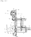
- the holding portions Tb have anchoring holes Tc in predetermined areas thereof and are therefore anchorable by anchor members 2 included in the blood purification apparatus 1.
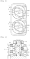
- the rotor R has the upper guide pin a1 and the lower guide pin a2 provided in a pair, and the upper guide pin b1 and the lower guide pin b2 provided in a pair, all of which project from the rotor R.
- the pump tube C is to be fitted between the upper guide pin a1 and the lower guide pin a2 and between the upper guide pin b1 and the lower guide pin b2.
- the upper guide pins a1 and b1 are positioned on the open side of the fitting recess Sa.
- the lower guide pins a2 and b2 are positioned on the bottom side of the fitting recess Sa.
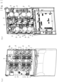
- an interlocking member 6 connected to an operating portion 5 and interlocking members 7 connected to the anchor members 2 are attached to the displacing portion 3.
- the displacing portion 3 moves while being guided by the guiding portions 4 (moves in the lateral direction in the drawings). With this movement, the anchor members 2 can be moved.
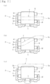
- the anchor hooks 2a are hooked on the attaching member T with the anchor members 2 being positioned apart from the predetermined position Ba, the attaching member T can rest at the unset position.
- the displacing portion 3 is operated to slide in such a manner as to move the anchor members 2 to positions near the predetermined position Ba, whereby the attaching member T can rest at the set position.
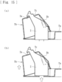
- the attaching member T when the attaching member T is positioned by the positioning pin g and is anchored at the anchoring holes Tc by the anchor hooks 2a of the anchor members 2 (see Fig. 15(a) ), the attaching member T rests at the unset position. In such a state, as illustrated in Fig. 6(a) , the proximal portions Ca and the distal portion Cb of each of the pump tubes C held by the holding portions Tb are positioned above the upper guide pins a1 and b1 of a corresponding one of the peristaltic pumps P (at an inappropriate position deviating from the appropriate position).
- the detecting unit 9 is provided with a stopper 10b at the proximal end thereof.
- a resistor 10a is fixed to a supporting frame f2 at a position near the proximal end of the detecting unit 9.
- the resistor 10a and the stopper 10b form a potentiometer 10.
- the detecting unit 9 is moved to move the stopper 10b, the resistor 10a converts the movement into a voltage corresponding to the length of travel or position of the stopper 10b (i.e., the length of travel or position of the detecting unit 9).
- the potentiometer 10 can output the voltage.
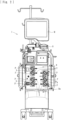
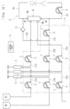
- the pump tubes C of the attaching member T are connected to the flow routes (the first substitution line L2a, the second substitution line L2b, and the pre-substitution line L2c) through which the substitution fluid is introduced into the blood circuit U, the flow routes (the first dialysate introduction line L1a and the second dialysate introduction line L1b) through which the dialysate is introduced into the dialyzer Q (a blood purifier) connected to the blood circuit U, and the flow routes (the first drain-liquid discharge line L3a and the second drain-liquid discharge line L3b) through which the drain liquid is discharged from the dialyzer Q (the blood purifier).
- the post-substitution line L2d may also be connected to one of the pump tubes C of the attaching member T.
- the peristaltic pump P is one of a plurality of peristaltic pumps P.
- the pump tube C is one of a plurality of pump tubes attached to the attaching member T.
- the number of the plurality of pump tubes C is equal to the number of the plurality of peristaltic pumps P.
- the plurality of pump tubes C are loaded or unloaded by moving the anchor member 2 between the set position and the unset position. Therefore, the plurality of pump tubes C can be loaded or unloaded at a time. Consequently, work hours can be reduced.
Landscapes
- Health & Medical Sciences (AREA)
- Heart & Thoracic Surgery (AREA)
- Engineering & Computer Science (AREA)
- Cardiology (AREA)
- General Health & Medical Sciences (AREA)
- Public Health (AREA)
- Biomedical Technology (AREA)
- Hematology (AREA)
- Life Sciences & Earth Sciences (AREA)
- Animal Behavior & Ethology (AREA)
- Veterinary Medicine (AREA)
- Anesthesiology (AREA)
- Mechanical Engineering (AREA)
- Urology & Nephrology (AREA)
- Vascular Medicine (AREA)
- Physics & Mathematics (AREA)
- Electromagnetism (AREA)
- Pulmonology (AREA)
- Emergency Medicine (AREA)
- External Artificial Organs (AREA)
Claims (6)
- Ein Blutreinigungsapparat (1), umfassend:eine peristaltische Pumpe (P), die einen Stator (S), an dem ein Pumpenschlauch (C), der einen ersten Abschnitt und einen zweiten Abschnitt beinhaltet, abnehmbar befestigt ist, und einen Rotor (R), der eine Walze (Ra) und einen Führungsabschnitt aufweist, beinhaltet, wobei die Walze (Ra) Flüssigkeit durch Zusammendrücken des am Stator (S) angebrachten Pumpenschlauchs (C) fördert, wobei der Führungsabschnitt den Pumpenschlauch (C) an einer geeigneten Position hält, an der der Pumpenschlauch (C) mit der Walze (Ra) zusammengedrückt werden kann, wobei der Rotor (R) um eine vorbestimmte Achse drehbar ist;ein Ankerelement (2), das ein Anbringungselement (T) verankert, an dem der Pumpenschlauch (C) angebracht ist; undeinen Verlagerungsabschnitt (3), der das Anbringungselement (T) zwischen einer eingerichteten Position und einer nicht-eingerichteten Position verlagert, indem das Ankerelement (2) bewegt wird, während das Anbringungselement (T) durch das Ankerelement (2) verankert ist,wobei ein Anbringungszustand, in dem der erste Abschnitt des Pumpenschlauchs (C) an der geeigneten Position ruht, hergestellt wird, wenn das Verankerungselement (2) von der nicht-eingerichteten Position in die eingerichtete Position bewegt wird, wobei der Führungsabschnitt der Peristaltikpumpe (P) in einer bestimmten Phase angehalten wird, und ein Beladevorgang, bei dem der Führungsabschnitt den Pumpenschlauch (C) in den Stator (S) zieht, so dass der erste Abschnitt und der zweite Abschnitt des Pumpenschlauchs (C) an der geeigneten Position ruhen, ausgeführt wird, wenn die Peristaltikpumpe (P) in dem Anbringungszustand aktiviert wird, so dass der Rotor (R) um einen vorbestimmten Winkel gedreht wird, und/oderein abnehmbarer Zustand, in dem der erste Abschnitt des Pumpenschlauchs (C) an einer ungeeigneten Position ruht, die von der geeigneten Position abweicht, hergestellt wird, wenn das Verankerungselement (2) von der eingerichteten Position in die nicht-eingerichtete Position bewegt wird, wobei der Führungsabschnitt der Peristaltikpumpe (P) in einer bestimmten Phase angehalten wird, und ein Entladevorgang, bei dem der Führungsabschnitt den Pumpenschlauch (C) aus dem Stator (S) herausdrückt, so dass der erste Abschnitt und der zweite Abschnitt des Pumpenschlauchs (C) an der ungeeigneten Position ruhen, ausgeführt wird, wenn die Peristaltikpumpe (P) im abnehmbaren Zustand aktiviert wird, so dass der Rotor (R) um einen vorbestimmten Winkel gedreht wird,dadurch gekennzeichnet, dass die Peristaltikpumpe (P) eine von einer Vielzahl von Peristaltikpumpen (P) ist, der Pumpenschlauch (C) einer von einer Vielzahl von Pumpenschläuchen (C) ist, die an dem Anbringungselement (T) angebracht sind, eine Anzahl der Vielzahl von Pumpenschläuchen (C) gleich einer Anzahl der Vielzahl von Peristaltikpumpen (P) ist, und die Vielzahl von Pumpenschläuchen (C) durch Bewegen des Ankerelements (2) zwischen der einsatzbereiten Position und der nicht-einsatzbereiten Position be- oder entladen wird.
- Der Blutreinigungsapparat (1) gemäß Anspruch 1, der ferner eine Steuereinheit (11) umfasst, die den Rotor (R) anhält, wenn sich der Führungsabschnitt in der spezifischen Phase befindet, und das Laden oder Entladen durch Drehen des Rotors (R) um den vorbestimmten Winkel ausführt.
- Der Blutreinigungsapparat (1) gemäß Anspruch 1 oder 2, der ferner einen Betätigungsabschnitt umfasst, mit dem der Verlagerungsabschnitt (3) auf eine solche Weise betätigt wird, dass das Anbringungselement (T) zwischen der eingerichteten Position und der nicht-eingerichteten Position durch Bewegen des Verankerungselements (2) verschoben wird, wobei der Betätigungsabschnitt eine Hilfsfunktion zum Unterstützen der Ausübung einer Betätigungskraft aufweist.
- Der Blutreinigungsapparat (1) gemäß einem der Ansprüche 1 bis 3, der ferner eine Erfassungseinheit (9) umfasst, die die Herstellung des Anbringungszustand oder des abnehmbaren Zustands des Pumpenschlauchs (C) erfasst.
- Der Blutreinigungsapparat (1) nach Anspruch 4, wobei die Erfassungseinheit (9) jeden der Pumpenschläuche (C) erfasst, der sich nicht im Anbringungszustand oder im abnehmbaren Zustand befindet, und eine der peristaltischen Pumpen (P) identifiziert, die dem erfassten Pumpenschlauch (C) entspricht.
- Der Blutreinigungsapparat (1) gemäß Anspruch 5, wobei die Erfassungseinheit (9) die Herstellung des Anbringungszustand oder des abnehmbaren Zustands der Pumpenschläuche (C) erfasst, die auf benachbarte Peristaltikpumpen (P) beladen oder von diesen entladen werden sollen.
Applications Claiming Priority (2)
| Application Number | Priority Date | Filing Date | Title |
|---|---|---|---|
| JP2018246177A JP6777721B2 (ja) | 2018-12-27 | 2018-12-27 | 血液浄化装置 |
| PCT/JP2019/051340 WO2020138384A1 (ja) | 2018-12-27 | 2019-12-26 | 血液浄化装置 |
Publications (3)
| Publication Number | Publication Date |
|---|---|
| EP3878488A1 EP3878488A1 (de) | 2021-09-15 |
| EP3878488A4 EP3878488A4 (de) | 2022-08-17 |
| EP3878488B1 true EP3878488B1 (de) | 2025-04-09 |
Family
ID=71126043
Family Applications (1)
| Application Number | Title | Priority Date | Filing Date |
|---|---|---|---|
| EP19902995.0A Active EP3878488B1 (de) | 2018-12-27 | 2019-12-26 | Blutreinigungsapparat |
Country Status (5)
| Country | Link |
|---|---|
| US (1) | US12016986B2 (de) |
| EP (1) | EP3878488B1 (de) |
| JP (1) | JP6777721B2 (de) |
| CN (1) | CN113226437B (de) |
| WO (1) | WO2020138384A1 (de) |
Families Citing this family (2)
| Publication number | Priority date | Publication date | Assignee | Title |
|---|---|---|---|---|
| JP2024003364A (ja) | 2022-06-27 | 2024-01-15 | 日機装株式会社 | 血液浄化装置 |
| CN119618617B (zh) * | 2025-01-21 | 2025-08-01 | 河南省驼人医疗科技有限公司 | 一种用于检测泵管管路流量的检测装置及检测方法 |
Family Cites Families (19)
| Publication number | Priority date | Publication date | Assignee | Title |
|---|---|---|---|---|
| US3771658A (en) * | 1971-10-20 | 1973-11-13 | R Brumfield | Blood transport membrane pump |
| JPS60148069U (ja) | 1984-03-15 | 1985-10-01 | 日本レギユレ−タ−株式会社 | マ−キング用ノズル |
| JP3452073B2 (ja) * | 1993-08-25 | 2003-09-29 | サイテック株式会社 | チューブ着脱手段付きローラーポンプ |
| US5462416A (en) | 1993-12-22 | 1995-10-31 | Baxter International Inc. | Peristaltic pump tube cassette for blood processing systems |
| US5634907A (en) * | 1994-12-22 | 1997-06-03 | Sandoz Nutrition Ltd. | System for detection of fluid infusion |
| CA2218899A1 (en) | 1995-06-07 | 1996-12-19 | Edward V. Cruz | Extracorporeal blood processing methods and apparatus |
| US7211037B2 (en) | 2002-03-04 | 2007-05-01 | Therakos, Inc. | Apparatus for the continuous separation of biological fluids into components and method of using same |
| JPWO2005088132A1 (ja) * | 2004-03-12 | 2008-04-24 | 株式会社メディカルシード | ローラ型ポンプ |
| JP2006212050A (ja) | 2005-02-01 | 2006-08-17 | Jms Co Ltd | ハウジング付きローラーポンプ、および該ローラーポンプを備えた医療用システム |
| JP4812101B2 (ja) * | 2006-06-23 | 2011-11-09 | 日機装株式会社 | しごき型ポンプ及びその可撓性チューブの取り外し方法 |
| JP5397747B2 (ja) | 2009-02-16 | 2014-01-22 | ニプロ株式会社 | チューブポンプ |
| CN109044416A (zh) | 2011-12-16 | 2018-12-21 | 史赛克公司 | 从在医学/外科手术期间产生的流体流提取组织样本的系统 |
| EP2610439A1 (de) | 2011-12-30 | 2013-07-03 | Siemens Aktiengesellschaft | Verfahren zum Ziehen und/oder Einsetzen eines Turbinenlagers sowie Vorrichtung zur Durchführung des Verfahrens |
| DE102012105918A1 (de) | 2012-07-03 | 2014-01-09 | B. Braun Avitum Ag | Multikonnektor und medizinisches Gerät zur extrakorporalen Blutbehandlung mit Multikonnektorerkennung |
| JP6226688B2 (ja) | 2013-10-11 | 2017-11-08 | 旭化成メディカル株式会社 | 液体回路 |
| JP5863871B2 (ja) * | 2014-04-15 | 2016-02-17 | 日機装株式会社 | 装着部材及びしごき型ポンプ |
| JP2017164285A (ja) | 2016-03-16 | 2017-09-21 | 川澄化学工業株式会社 | 血液回路パネル、血液浄化装置及び血液回路の接続チューブの固定方法 |
| JP6356872B2 (ja) | 2017-05-29 | 2018-07-11 | 日機装株式会社 | 収納トレイ |
| IT201700064361A1 (it) | 2017-06-09 | 2018-12-09 | Allmed Medical Care Holdings Ltd | Supporto per una porzione curva di un condotto |
-
2018
- 2018-12-27 JP JP2018246177A patent/JP6777721B2/ja active Active
-
2019
- 2019-12-26 WO PCT/JP2019/051340 patent/WO2020138384A1/ja not_active Ceased
- 2019-12-26 CN CN201980085668.1A patent/CN113226437B/zh active Active
- 2019-12-26 EP EP19902995.0A patent/EP3878488B1/de active Active
-
2021
- 2021-06-22 US US17/355,085 patent/US12016986B2/en active Active
Also Published As
| Publication number | Publication date |
|---|---|
| EP3878488A1 (de) | 2021-09-15 |
| US20210316050A1 (en) | 2021-10-14 |
| JP6777721B2 (ja) | 2020-10-28 |
| JP2020103644A (ja) | 2020-07-09 |
| CN113226437B (zh) | 2024-07-05 |
| US12016986B2 (en) | 2024-06-25 |
| WO2020138384A1 (ja) | 2020-07-02 |
| EP3878488A4 (de) | 2022-08-17 |
| CN113226437A (zh) | 2021-08-06 |
Similar Documents
| Publication | Publication Date | Title |
|---|---|---|
| US12016986B2 (en) | Blood purification apparatus using peristaltic pumps to circulate a liquid for blood treatment | |
| US12246118B2 (en) | Attaching member | |
| US11554202B2 (en) | Blood purification apparatus and method of discharging bubbles therefrom | |
| US12128167B2 (en) | Attaching member | |
| JP4980892B2 (ja) | 薬液注入装置 | |
| EP3878489B1 (de) | Befestigungselement | |
| US12214115B2 (en) | Attaching member | |
| US12527902B2 (en) | Attaching member | |
| CA3185683A1 (en) | Method for disconnection | |
| EP4545113A1 (de) | Blutreinigungsvorrichtung |
Legal Events
| Date | Code | Title | Description |
|---|---|---|---|
| STAA | Information on the status of an ep patent application or granted ep patent |
Free format text: STATUS: THE INTERNATIONAL PUBLICATION HAS BEEN MADE |
|
| PUAI | Public reference made under article 153(3) epc to a published international application that has entered the european phase |
Free format text: ORIGINAL CODE: 0009012 |
|
| STAA | Information on the status of an ep patent application or granted ep patent |
Free format text: STATUS: REQUEST FOR EXAMINATION WAS MADE |
|
| 17P | Request for examination filed |
Effective date: 20210609 |
|
| AK | Designated contracting states |
Kind code of ref document: A1 Designated state(s): AL AT BE BG CH CY CZ DE DK EE ES FI FR GB GR HR HU IE IS IT LI LT LU LV MC MK MT NL NO PL PT RO RS SE SI SK SM TR |
|
| DAV | Request for validation of the european patent (deleted) | ||
| DAX | Request for extension of the european patent (deleted) | ||
| REG | Reference to a national code |
Ref legal event code: R079 Ipc: A61M0001160000 Ref country code: DE Ref legal event code: R079 Ref document number: 602019068574 Country of ref document: DE Free format text: PREVIOUS MAIN CLASS: A61M0001100000 Ipc: A61M0001160000 |
|
| A4 | Supplementary search report drawn up and despatched |
Effective date: 20220718 |
|
| RIC1 | Information provided on ipc code assigned before grant |
Ipc: A61M 60/462 20210101ALI20220712BHEP Ipc: A61M 60/37 20210101ALI20220712BHEP Ipc: A61M 60/279 20210101ALI20220712BHEP Ipc: A61M 60/113 20210101ALI20220712BHEP Ipc: A61M 1/36 20060101ALI20220712BHEP Ipc: A61M 1/34 20060101ALI20220712BHEP Ipc: A61M 1/16 20060101AFI20220712BHEP |
|
| P01 | Opt-out of the competence of the unified patent court (upc) registered |
Effective date: 20230523 |
|
| GRAP | Despatch of communication of intention to grant a patent |
Free format text: ORIGINAL CODE: EPIDOSNIGR1 |
|
| STAA | Information on the status of an ep patent application or granted ep patent |
Free format text: STATUS: GRANT OF PATENT IS INTENDED |
|
| RIC1 | Information provided on ipc code assigned before grant |
Ipc: A61M 60/835 20210101ALI20241105BHEP Ipc: A61M 60/462 20210101ALI20241105BHEP Ipc: A61M 60/37 20210101ALI20241105BHEP Ipc: A61M 60/279 20210101ALI20241105BHEP Ipc: A61M 60/113 20210101ALI20241105BHEP Ipc: A61M 1/36 20060101ALI20241105BHEP Ipc: A61M 1/34 20060101ALI20241105BHEP Ipc: A61M 1/16 20060101AFI20241105BHEP |
|
| INTG | Intention to grant announced |
Effective date: 20241118 |
|
| RIN1 | Information on inventor provided before grant (corrected) |
Inventor name: OHTA, MASAAKI Inventor name: EDA, YUKI |
|
| GRAS | Grant fee paid |
Free format text: ORIGINAL CODE: EPIDOSNIGR3 |
|
| GRAA | (expected) grant |
Free format text: ORIGINAL CODE: 0009210 |
|
| STAA | Information on the status of an ep patent application or granted ep patent |
Free format text: STATUS: THE PATENT HAS BEEN GRANTED |
|
| AK | Designated contracting states |
Kind code of ref document: B1 Designated state(s): AL AT BE BG CH CY CZ DE DK EE ES FI FR GB GR HR HU IE IS IT LI LT LU LV MC MK MT NL NO PL PT RO RS SE SI SK SM TR |
|
| REG | Reference to a national code |
Ref country code: GB Ref legal event code: FG4D |
|
| REG | Reference to a national code |
Ref country code: CH Ref legal event code: EP |
|
| REG | Reference to a national code |
Ref country code: DE Ref legal event code: R096 Ref document number: 602019068574 Country of ref document: DE |
|
| REG | Reference to a national code |
Ref country code: IE Ref legal event code: FG4D |
|
| REG | Reference to a national code |
Ref country code: SE Ref legal event code: TRGR |
|
| REG | Reference to a national code |
Ref country code: NL Ref legal event code: MP Effective date: 20250409 |
|
| PG25 | Lapsed in a contracting state [announced via postgrant information from national office to epo] |
Ref country code: NL Free format text: LAPSE BECAUSE OF FAILURE TO SUBMIT A TRANSLATION OF THE DESCRIPTION OR TO PAY THE FEE WITHIN THE PRESCRIBED TIME-LIMIT Effective date: 20250409 |
|
| REG | Reference to a national code |
Ref country code: AT Ref legal event code: MK05 Ref document number: 1782988 Country of ref document: AT Kind code of ref document: T Effective date: 20250409 |
|
| PG25 | Lapsed in a contracting state [announced via postgrant information from national office to epo] |
Ref country code: FI Free format text: LAPSE BECAUSE OF FAILURE TO SUBMIT A TRANSLATION OF THE DESCRIPTION OR TO PAY THE FEE WITHIN THE PRESCRIBED TIME-LIMIT Effective date: 20250409 Ref country code: PT Free format text: LAPSE BECAUSE OF FAILURE TO SUBMIT A TRANSLATION OF THE DESCRIPTION OR TO PAY THE FEE WITHIN THE PRESCRIBED TIME-LIMIT Effective date: 20250811 Ref country code: ES Free format text: LAPSE BECAUSE OF FAILURE TO SUBMIT A TRANSLATION OF THE DESCRIPTION OR TO PAY THE FEE WITHIN THE PRESCRIBED TIME-LIMIT Effective date: 20250409 |
|
| REG | Reference to a national code |
Ref country code: LT Ref legal event code: MG9D |
|
| PG25 | Lapsed in a contracting state [announced via postgrant information from national office to epo] |
Ref country code: NO Free format text: LAPSE BECAUSE OF FAILURE TO SUBMIT A TRANSLATION OF THE DESCRIPTION OR TO PAY THE FEE WITHIN THE PRESCRIBED TIME-LIMIT Effective date: 20250709 Ref country code: GR Free format text: LAPSE BECAUSE OF FAILURE TO SUBMIT A TRANSLATION OF THE DESCRIPTION OR TO PAY THE FEE WITHIN THE PRESCRIBED TIME-LIMIT Effective date: 20250710 |
|
| PG25 | Lapsed in a contracting state [announced via postgrant information from national office to epo] |
Ref country code: PL Free format text: LAPSE BECAUSE OF FAILURE TO SUBMIT A TRANSLATION OF THE DESCRIPTION OR TO PAY THE FEE WITHIN THE PRESCRIBED TIME-LIMIT Effective date: 20250409 |
|
| PG25 | Lapsed in a contracting state [announced via postgrant information from national office to epo] |
Ref country code: BG Free format text: LAPSE BECAUSE OF FAILURE TO SUBMIT A TRANSLATION OF THE DESCRIPTION OR TO PAY THE FEE WITHIN THE PRESCRIBED TIME-LIMIT Effective date: 20250409 |
|
| PG25 | Lapsed in a contracting state [announced via postgrant information from national office to epo] |
Ref country code: HR Free format text: LAPSE BECAUSE OF FAILURE TO SUBMIT A TRANSLATION OF THE DESCRIPTION OR TO PAY THE FEE WITHIN THE PRESCRIBED TIME-LIMIT Effective date: 20250409 |
|
| PG25 | Lapsed in a contracting state [announced via postgrant information from national office to epo] |
Ref country code: AT Free format text: LAPSE BECAUSE OF FAILURE TO SUBMIT A TRANSLATION OF THE DESCRIPTION OR TO PAY THE FEE WITHIN THE PRESCRIBED TIME-LIMIT Effective date: 20250409 |
|
| PG25 | Lapsed in a contracting state [announced via postgrant information from national office to epo] |
Ref country code: RS Free format text: LAPSE BECAUSE OF FAILURE TO SUBMIT A TRANSLATION OF THE DESCRIPTION OR TO PAY THE FEE WITHIN THE PRESCRIBED TIME-LIMIT Effective date: 20250709 |
|
| PG25 | Lapsed in a contracting state [announced via postgrant information from national office to epo] |
Ref country code: IS Free format text: LAPSE BECAUSE OF FAILURE TO SUBMIT A TRANSLATION OF THE DESCRIPTION OR TO PAY THE FEE WITHIN THE PRESCRIBED TIME-LIMIT Effective date: 20250809 |
|
| PG25 | Lapsed in a contracting state [announced via postgrant information from national office to epo] |
Ref country code: LV Free format text: LAPSE BECAUSE OF FAILURE TO SUBMIT A TRANSLATION OF THE DESCRIPTION OR TO PAY THE FEE WITHIN THE PRESCRIBED TIME-LIMIT Effective date: 20250409 |
|
| PGFP | Annual fee paid to national office [announced via postgrant information from national office to epo] |
Ref country code: DE Payment date: 20251216 Year of fee payment: 7 |
|
| PGFP | Annual fee paid to national office [announced via postgrant information from national office to epo] |
Ref country code: GB Payment date: 20251218 Year of fee payment: 7 |
|
| REG | Reference to a national code |
Ref country code: DE Ref legal event code: R097 Ref document number: 602019068574 Country of ref document: DE |
|
| PG25 | Lapsed in a contracting state [announced via postgrant information from national office to epo] |
Ref country code: SM Free format text: LAPSE BECAUSE OF FAILURE TO SUBMIT A TRANSLATION OF THE DESCRIPTION OR TO PAY THE FEE WITHIN THE PRESCRIBED TIME-LIMIT Effective date: 20250409 Ref country code: DK Free format text: LAPSE BECAUSE OF FAILURE TO SUBMIT A TRANSLATION OF THE DESCRIPTION OR TO PAY THE FEE WITHIN THE PRESCRIBED TIME-LIMIT Effective date: 20250409 |
|
| PGFP | Annual fee paid to national office [announced via postgrant information from national office to epo] |
Ref country code: FR Payment date: 20251218 Year of fee payment: 7 |
|
| PGFP | Annual fee paid to national office [announced via postgrant information from national office to epo] |
Ref country code: SE Payment date: 20251217 Year of fee payment: 7 |
|
| PG25 | Lapsed in a contracting state [announced via postgrant information from national office to epo] |
Ref country code: CZ Free format text: LAPSE BECAUSE OF FAILURE TO SUBMIT A TRANSLATION OF THE DESCRIPTION OR TO PAY THE FEE WITHIN THE PRESCRIBED TIME-LIMIT Effective date: 20250409 |
|
| PG25 | Lapsed in a contracting state [announced via postgrant information from national office to epo] |
Ref country code: EE Free format text: LAPSE BECAUSE OF FAILURE TO SUBMIT A TRANSLATION OF THE DESCRIPTION OR TO PAY THE FEE WITHIN THE PRESCRIBED TIME-LIMIT Effective date: 20250409 |
|
| PG25 | Lapsed in a contracting state [announced via postgrant information from national office to epo] |
Ref country code: SK Free format text: LAPSE BECAUSE OF FAILURE TO SUBMIT A TRANSLATION OF THE DESCRIPTION OR TO PAY THE FEE WITHIN THE PRESCRIBED TIME-LIMIT Effective date: 20250409 Ref country code: RO Free format text: LAPSE BECAUSE OF FAILURE TO SUBMIT A TRANSLATION OF THE DESCRIPTION OR TO PAY THE FEE WITHIN THE PRESCRIBED TIME-LIMIT Effective date: 20250409 |
|
| PLBE | No opposition filed within time limit |
Free format text: ORIGINAL CODE: 0009261 |
|
| STAA | Information on the status of an ep patent application or granted ep patent |
Free format text: STATUS: NO OPPOSITION FILED WITHIN TIME LIMIT |
|
| REG | Reference to a national code |
Ref country code: CH Ref legal event code: L10 Free format text: ST27 STATUS EVENT CODE: U-0-0-L10-L00 (AS PROVIDED BY THE NATIONAL OFFICE) Effective date: 20260218 |
|
| 26N | No opposition filed |
Effective date: 20260112 |
|
| PGFP | Annual fee paid to national office [announced via postgrant information from national office to epo] |
Ref country code: IT Payment date: 20251231 Year of fee payment: 7 |