EP3878570A1 - Verfahren und vorrichtung zur formung eines rohrförmigen teils, rohrförmiges teil und leiter - Google Patents
Verfahren und vorrichtung zur formung eines rohrförmigen teils, rohrförmiges teil und leiter Download PDFInfo
- Publication number
- EP3878570A1 EP3878570A1 EP20161798.2A EP20161798A EP3878570A1 EP 3878570 A1 EP3878570 A1 EP 3878570A1 EP 20161798 A EP20161798 A EP 20161798A EP 3878570 A1 EP3878570 A1 EP 3878570A1
- Authority
- EP
- European Patent Office
- Prior art keywords
- tubular piece
- punch
- tubular
- circumferential surface
- separate parts
- Prior art date
- Legal status (The legal status is an assumption and is not a legal conclusion. Google has not performed a legal analysis and makes no representation as to the accuracy of the status listed.)
- Pending
Links
- 238000000034 method Methods 0.000 title claims abstract description 37
- 238000004519 manufacturing process Methods 0.000 claims abstract description 6
- 238000003825 pressing Methods 0.000 claims description 10
- 230000010355 oscillation Effects 0.000 claims description 3
- 239000011248 coating agent Substances 0.000 description 2
- 238000000576 coating method Methods 0.000 description 2
- 239000000463 material Substances 0.000 description 2
- 230000009194 climbing Effects 0.000 description 1
- 230000007797 corrosion Effects 0.000 description 1
- 238000005260 corrosion Methods 0.000 description 1
- 230000001419 dependent effect Effects 0.000 description 1
- 230000006353 environmental stress Effects 0.000 description 1
- 239000002184 metal Substances 0.000 description 1
- 238000005096 rolling process Methods 0.000 description 1
Images



Classifications
-
- B—PERFORMING OPERATIONS; TRANSPORTING
- B21—MECHANICAL METAL-WORKING WITHOUT ESSENTIALLY REMOVING MATERIAL; PUNCHING METAL
- B21D—WORKING OR PROCESSING OF SHEET METAL OR METAL TUBES, RODS OR PROFILES WITHOUT ESSENTIALLY REMOVING MATERIAL; PUNCHING METAL
- B21D41/00—Application of procedures in order to alter the diameter of tube ends
- B21D41/04—Reducing; Closing
-
- B—PERFORMING OPERATIONS; TRANSPORTING
- B21—MECHANICAL METAL-WORKING WITHOUT ESSENTIALLY REMOVING MATERIAL; PUNCHING METAL
- B21D—WORKING OR PROCESSING OF SHEET METAL OR METAL TUBES, RODS OR PROFILES WITHOUT ESSENTIALLY REMOVING MATERIAL; PUNCHING METAL
- B21D15/00—Corrugating tubes
-
- B—PERFORMING OPERATIONS; TRANSPORTING
- B21—MECHANICAL METAL-WORKING WITHOUT ESSENTIALLY REMOVING MATERIAL; PUNCHING METAL
- B21D—WORKING OR PROCESSING OF SHEET METAL OR METAL TUBES, RODS OR PROFILES WITHOUT ESSENTIALLY REMOVING MATERIAL; PUNCHING METAL
- B21D22/00—Shaping without cutting, by stamping, spinning, or deep-drawing
- B21D22/02—Stamping using rigid devices or tools
- B21D22/025—Stamping using rigid devices or tools for tubular articles
-
- B—PERFORMING OPERATIONS; TRANSPORTING
- B21—MECHANICAL METAL-WORKING WITHOUT ESSENTIALLY REMOVING MATERIAL; PUNCHING METAL
- B21D—WORKING OR PROCESSING OF SHEET METAL OR METAL TUBES, RODS OR PROFILES WITHOUT ESSENTIALLY REMOVING MATERIAL; PUNCHING METAL
- B21D22/00—Shaping without cutting, by stamping, spinning, or deep-drawing
- B21D22/02—Stamping using rigid devices or tools
- B21D22/04—Stamping using rigid devices or tools for dimpling
-
- B—PERFORMING OPERATIONS; TRANSPORTING
- B21—MECHANICAL METAL-WORKING WITHOUT ESSENTIALLY REMOVING MATERIAL; PUNCHING METAL
- B21D—WORKING OR PROCESSING OF SHEET METAL OR METAL TUBES, RODS OR PROFILES WITHOUT ESSENTIALLY REMOVING MATERIAL; PUNCHING METAL
- B21D39/00—Application of procedures in order to connect objects or parts, e.g. coating with sheet metal otherwise than by plating; Tube expanders
- B21D39/06—Application of procedures in order to connect objects or parts, e.g. coating with sheet metal otherwise than by plating; Tube expanders of tubes in openings, e.g. rolling-in
- B21D39/063—Application of procedures in order to connect objects or parts, e.g. coating with sheet metal otherwise than by plating; Tube expanders of tubes in openings, e.g. rolling-in for assembling ladders
Definitions
- the present disclosure relates to a method and apparatus for forming tubular pieces, and more particularly such tubular pieces to be used as rungs of a ladder.
- the present disclosure further concerns the such a tubular piece and an associated ladder.
- Tubular pieces have generally been used as rungs for ladders. Moreover, it is generally desirable to have an embossed pattern on the surface of the rung, so as to improve the grip, thus making the ladder safer.
- Known methods for achieving an embossed pattern on a tubular piece for a rung include, e.g. forming an embossed pattern on sheet metal, and then rolling the sheet into a tubular piece.
- this does not result in truly closed tubular profile, unless the piece is subsequently welded, or otherwise attached to close the profile in a subsequent process.
- a closed profile is desirable, because the structural strength thereof is much higher as compared to a corresponding non-closed profile.
- Another alternative is to take an already tubular piece and punch holes therethrough, i.e. in from one side and out from one side.
- punch holes i.e. in from one side and out from one side.
- this results in holes being formed in the tubular piece, resulting in a weakened structural strength.
- this will damage any possible coating, such as a galvanization layer, making the piece more susceptible to corrosion.
- An object of the present disclosure is to provide a method and apparatus for forming tubular pieces, in which the structural integrity of the tubular piece is maintained, and such a tubular piece. It is a further object of the present disclosure to provide a method for manufacturing a ladder having such tubular pieces as rungs, and such a ladder.
- the object of the disclosure is achieved by a method and an apparatus for forming a tubular piece, a tubular piece, a method for manufacturing a ladder, and such a ladder, which are characterized by what is stated in the independent claims.
- the preferred embodiments of the disclosure are disclosed in the dependent claims.
- the disclosure is based on the idea of providing a punch comprising at least two parts and having protuberances thereon.
- the punch is inserted into the tubular piece to be formed (or the tubular piece is inserted onto the punch), and a tapered wedge placed between the parts of the punch is pulled, such that the separate parts of the punch are pushed against the inner surface of the tubular piece.
- the protuberances on the punch deform the wall of the tubular pieces, thus forming a corresponding embossed pattern on the outer surface of the tubular piece.
- An advantage of the disclosure is that the structural integrity of the tubular piece is maintained, resulting in a higher structural strength as compared to forming which breaks the structure of the piece, and additionally, a possible coating is maintained unbroken, resulting in improved resistance to environmental stress.
- a method for forming a tubular piece is provided.
- a tubular piece 2 is positioned on top of a punch 4, such that the punch 4 resides within the tubular piece 2.
- the tubular piece 2 is then held on top of the punch 4 in a longitudinally and rotationally secured manner.
- the punch 4 comprises at least two separate parts 4', 4".
- the at least two separate parts 4', 4" are of a longitudinally extending shape and longitudinally separated from each other, so as to allow relative movement therebetween in a direction transverse to the longitudinal.
- the method further comprises a following step of drawing a longitudinal, tapered wedge 5 positioned between the separate parts 4', 4" of the punch 4 so as to push the separate parts 4', 4" of the punch 4 towards an inner circumferential surface 2a of the tubular piece 2.
- Drawing of the punch 4 is suitably carried out by drawing it from an extracted position (i.e. initial position of the wedge) to a retracted position.
- the tubular piece 2 may then be removed off from the punch 4.
- the wedge 5 is returned to its initial position before removal of the tubular piece 2.
- any grippers are used to secure the tubular piece 2 in place during drawing of the wedge 5, they may naturally be released before withdrawal of the tubular piece 2.
- the tooling portion 4a of the punch 4 is used to describe the portion of the punch 4 that is intended to be inserted into the tubular piece 2, or onto which the tubular piece 2 is intended to be inserted.
- the embossed pattern 2c comprises one or more elevated portions 2d elevated at a distance h of between 1,0 mm - 2,0 mm from a surrounding non-elevated portion of the outer circumferential surface 2b of the tubular piece 2 surrounding and adjacent to the respective elevated portion 2d.
- the elevated portions 2d are elevated at a distance h of between 1,1 mm - 1,5 mm from a surrounding non-elevated portion of the outer circumferential surface 2b of the tubular piece 2 surrounding and adjacent to the respective elevated portion 2d.
- the elevated portions 2d are elevated at a distance h of between 1,2 mm - 1,5 mm from a surrounding non-elevated portion of the outer circumferential surface 2b of the tubular piece 2 surrounding and adjacent to the respective elevated portion 2d.
- Elevated portions 2d dimensioned accordingly have been found to provide improved properties in terms of grip, when the tubular pieces 2 achieved are used as rungs of a ladder 7.
- the protuberances 4b on the tooling portion 4a of the punch may be dimensioned accordingly, so as to achieve desired dimensions of the elevate portions 2d on the tubular piece 2 of given material and material thickness.
- the embossed pattern 2c may comprise multiple elevated portions 2d having a frustum shape, preferably a frusto-conical shape.
- Such a frustum shape has been found to provide improved properties in terms of grip, when the tubular pieces 2 achieved are used as rungs of a ladder 7.
- Naturally other shapes such as spherical, frusto-spherical, polygonal, or frusto-polygonal shapes, for example, may be used.
- the sides of the one or more elevated portions 2d have a taper angle ⁇ of between 45° - 65°, preferably between 50° - 60°, and most preferably of 55° with respect to an axis perpendicular to a tangent of a middle point of the elevated portion.
- a plurality of embossed patterns 2c are formed on the outer circumferential surface 2b of the tubular piece 2.
- each embossed pattern 2c formed on the tubular piece extends along the longitudinal direction thereof, and preferably, the embossed patterns 2c on the tubular piece are circumferentially spaced apart from each other.
- each of the separate parts 4', 4" of the punch 4 comprises a respective tooling portion 4a comprising protuberances 4b facing towards the inner circumferential surface 2a of the tubular piece 2, such that drawing the wedge 5 causes the punch to form the wall of the tubular piece such that at least two corresponding embossed patterns are formed on the outer circumferential surface of the tubular piece, preferably on the opposite sides thereof. That is, each separate part 4', 4" forms a respective embossed pattern 2c. In this way multiple embossed patterns 2c are formed with a single draw of the tapered wedge 5.
- the method may further comprise, subsequent to the drawing of the wedge 5, returning the wedge 5 to an initial position thereof, and thereafter, rotating the tubular piece 2 about its longitudinal axis. Furthermore, the wedge 5 may be subsequently drawn between the separate parts 4', 4" of the punch 4 so as to push the separate parts 4', 4" again towards the inner circumferential surface 2a of the tubular piece 2.
- this sequence of returning the wedge 5 to its initial position, rotating the tubular piece 2 and re-drawing the wedge 5 may repeated multiple times, to achieve multiple embossed patterns 2c circumferentially spaced apart from each other.
- the method further comprises, prior to positioning the tubular piece 2 on top of the punch 4, pressing the separate parts 4', 4" of the punch towards each other. This facilitates fitting a distal end of the tooling portion 4a within the tubular piece 2.
- the method further comprises, during drawing of the wedge 5, holding a distal portion of the punch extending out of the tubular piece, so as prevent oscillation or vibration of the punch.
- the method may further comprise, following the forming of one or more embossed patterns 2c, pressing the tubular 2 piece so as to deform the cross-sectional shape thereof.
- the cross-sectional shape of the tubular piece 2 is formed so as to achieve a tear-drop shaped cross section.
- Such a tear-drop shaped cross-sectional profile has been found particularly advantageous, when the tubular piece 2 is us to be used as rungs of a roof ladder (i.e. when the ladder is inclined), because this allows an increased support area on side of the rung for the user to engage. Additionally, such a rotationally non-symmetric shape prevents the tubular piece 2 from rotating, with respect to a rail of a ladder, to which it is attached so as to form a rung of said ladder.
- the method may further comprise, following the forming of one or more embossed patterns 2c, pressing both longitudinal end portions of the tubular piece 2, so as to reduce the diameter thereof. If this is done in addition to forming the cross-sectional profile, as discussed above, the pressing of the longitudinal end portions is most suitably carried out most subsequently. Reducing the diameter of the longitudinal end portions facilitates attaching the tubular piece 2 to a rail of an ladder, as it forms a stopper surface, thus locking the movement of the rail in the longitudinal direction towards an opposing longitudinal end portion of the tubular piece 2 (i.e. rung).
- a method of manufacturing a ladder 6 is provided, which ladder comprises a pair of rails 7 and a plurality of rungs.
- the rungs have been formed as tubular pieces 2 in accordance with the first aspect of the present disclosure. Furthermore, the method comprises inserting longitudinal end portions of the rungs through corresponding openings in the rails 7.
- the rungs have been formed as tubular pieces 2 having their cross-sectional shape formed so as to achieve rotationally non-symmetric shape (such as a tear-drop shaped cross section), and their longitudinal end portions being shaped so as to reduce the diameter thereof.
- rotationally non-symmetric shape such as a tear-drop shaped cross section
- the rotationally non-symmetrical cross-sectional profile prevents the rung from rotating about its longitudinal axis.
- the ladder has an intended top end and an intended bottom end, such that the intended top end is to be installed higher than the intended bottom end.
- the rungs provided as tubular pieces 2 are formed to have a teardrop shaped cross-sectional profile, as discussed above in context of the first aspect of the present disclosure.
- the rungs are rotationally oriented about their respective longitudinal axis, such that the bulge of the teardrop shaped cross-sectional profile is oriented towards the intended bottom of the ladder.
- the blunt side is pointing towards the intended bottom of the ladder.
- This provides an increased contact area under a user's foot particularly for ladders that are to be used as roof ladders on roofs having a relative slight inclination such that the ladders will be walked on, as opposed to climbing.
- the rungs may be oriented such that the bulge of the teardrop shaped cross-sectional profile is oriented towards the intended top of the ladder, i.e. the blunt side of the rung is pointing towards the intended top of the ladder.
- Such an arrangement is more suitable for wall ladders and roof ladders for roof having a relatively steep inclination, such that the ladders will be climbed, as opposed to walking.
- an apparatus 1 for forming a tubular piece 2 is provided.
- the apparatus 1 comprises a frame 3 and a punch 4 formed of at least two separate parts 4', 4".
- the punch 4 is attached to the frame 3 in a longitudinally and rotationally secured manner, such that a movement of the separate parts 4', 4" with respect to each other in a direction transverse to the longitudinal is allowed.
- the punch 4 comprises at least a longitudinal tooling portion 4a having a plurality of protuberances 4b.
- the tooling portion 4a is configured to be inserted into the tubular piece 2 such that the protuberances 4b on the tooling portion 4a face towards an inner circumferential surface of the tubular piece 2a.
- the tooling portion 4a is configured such that a tubular piece 2 may be inserted thereon so that the protuberances 4b on the tooling portion 4a face towards an inner circumferential surface of the tubular piece 2a.
- the apparatus 1 further comprises a longitudinal wedge 5 positioned between the at least two separate parts 4', 4" of the punch and extending longitudinally therebetween.
- the apparatus 1 further comprises a drawing device 6 coupled to the frame 1 and the punch 4.
- the drawing device 6 is configured to draw the wedge 5 along a longitudinal direction between the at least two separate parts 4', 4" of the punch 4, so as to cause the at least two separate parts 4', 4" of the punch 4 to move away from each other in a direction transverse to the longitudinal.
- the drawings device 6 is also configured to return the wedge 5 into its initial position.
- the apparatus 1 may comprise a first gripper 1a for holding a distal end of the punch 4 projecting out of the tubular piece 2 when the tubular piece is formed 2.
- the first gripper 1a follows the movement of the separate parts 4', 4" away and towards each other while holding the distal end of the punch 4 firmly. This helps support the punch 4 and reduces undesired vibration of the punch 4 and the wedge 5 extendgin therefrom.
- the apparatus 1 may comprise a second gripper 1b for pressing the separate parts 4', 4" of the punch towards each other prior to positioning the tubular piece 2 on top of the punch 4.
- This facilitates fitting a distal end of the tooling portion 4a within the tubular piece 2.
- the second gripper 1b may also be used when withdrawing the tubular piece 2 off from the punch 4 after the tubular piece has been withdrawn past the position of the second gripper 1b. This facilitates removal of the tubular piece 2, protects the working surface 4a form damage caused by the tubular piece 2 sliding past.
- the apparatus may further comprise a guider (not illustrated) for supporting the wedge 5 extending out from the punch 4 and preventing excessive oscillation of the wedge during the drawing thereof.
- a guider may be provided as a gripper allowing sliding contact between itself and the wedge 5.
- the apparatus 1 may be equipped with an arrangement for rotating the tubular piece 2 between subsequent draws of the wedge 5. This may be done, e.g., with a robotic arm configured for manipulating the tubular piece 2. Such a robotic arm may additionally be used for inserting the tubular piece 2 onto the punch 4 and removing it therefrom. Naturally, such a robotic arm may be provided as a separate entity within the same manufacturing sell, for example.
- a tubular piece is provided. Particularly, such a tubular piece 2 is formed by the method according to the first aspect of the present disclosure.
- a ladder is provided. Particularly, such a ladder is formed by the method according to the second aspect of the present disclosure.
- Fig. 1a schematically illustrates an apparatus 1 for forming tubular piece 2 according to an embodiment of the present disclosure.
- the apparatus 1 has a frame 3 having a punch 4 attached to it.
- the punch extends in a longitudinal direction and has two separate parts 4', 4", the mutual movement of which is allowed in a direction transverse to the longitudinal.
- a tooling portion 4a extending out of the frame 3 is configured to be inserted into the tubular piece 2, and has protuberances 4b thereon.
- the tooling portion 4a is arrange on the two separate parts 4', 4", i.e. each of the parts have protuberances 4b thereon.
- the device further comprises a longitudinally extending wedge 5, the movement of which is allowed in the longitudinal direction.
- the wedge 5 is positioned between the separate parts of 4', 4" of the punch 4, and in the initial position of Fig. 1a , extends through and beyond the punch 4.
- the apparatus further comprises a drawing device 6 coupled to the frame 3.
- the drawing device 6 is configured to draw the wedge 5 along a longitudinal direction towards the frame 3, i.e. to its retracted position so as so as to cause the at least two separate parts 4', 4" of the punch 4 to move away from each other in a direction transverse to the longitudinal.
- the drawings device is implemented with a hydraulic actuator.
- the drawings device 6 is also configured to return the wedge 5 back to its initial, i.e. extracted position.
- the apparatus 1 of Fig. 1a further comprises a first gripper 1a for holding a distal end of the punch 4 projecting out from the tubular piece 2, after the tubular piece 2 has been placed onto the punch 4. Additionally, the apparatus of Fig. 1a further comprises a second gripper 1b for pressing the separate parts 4', 4" of the punch towards each other prior to positioning the tubular piece 2 on top of the punch 4. The second gripper 1b may also be used to press the separate parts 4', 4" of the punch towards each when the tubular piece 2 is withdrawn, after it has been withdrawn past the second gripper 1b.
- Fig. 1b schematically illustrates the apparatus of Fig. 1a with the wedge 5 being drawn into the retracted position, as seen as a partially cut plane view.
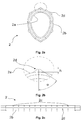
- Fig. 2a schematically illustrates a tubular piece according to an embodiment of the present disclosure as seen along the longitudinal direction thereof.
- a plurality of longitudinally extending embossed patterns 2c are formed on the outer circumference of the tubular piece 2, rotationally spaced apart from each other.
- the cross-sectional profile of the he tubular piece 2 has been formed into a rotationally non-symmetrical, tear-drop shape.
- Fig. 2b schematically illustrates a detailed view of an elevated portion of the tubular piece encircled in Fig. 2a .
- the elevated portions 2d have a frusto-conical shape with an elevation of h from a surrounding non-elevated portion of the outer circumferential surface 2b of the tubular piece 2 surrounding and adjacent to the respective elevated portion 2d.
- the elevated portion 2d has a taper angle ⁇ .
- Fig. 2c schematically illustrates a tubular piece 2 of Fig. 2a as seen along a direction transverse to the longitudinal direction of the tubular piece 2. Most notably, this clearly illustrates the manner in which the embossed patterns 2c extends longitudinally along the tubular piece 2.
- Fig. 3 illustrates a ladder according to an embodiment of the present disclosure as seen as a perspective view. Particularly, a plurality of tubular pieces 2 have provided between a pair of rails 7, in a well-known manner.
Landscapes
- Engineering & Computer Science (AREA)
- Mechanical Engineering (AREA)
- Shaping Metal By Deep-Drawing, Or The Like (AREA)
Priority Applications (1)
| Application Number | Priority Date | Filing Date | Title |
|---|---|---|---|
| EP20161798.2A EP3878570A1 (de) | 2020-03-09 | 2020-03-09 | Verfahren und vorrichtung zur formung eines rohrförmigen teils, rohrförmiges teil und leiter |
Applications Claiming Priority (1)
| Application Number | Priority Date | Filing Date | Title |
|---|---|---|---|
| EP20161798.2A EP3878570A1 (de) | 2020-03-09 | 2020-03-09 | Verfahren und vorrichtung zur formung eines rohrförmigen teils, rohrförmiges teil und leiter |
Publications (1)
| Publication Number | Publication Date |
|---|---|
| EP3878570A1 true EP3878570A1 (de) | 2021-09-15 |
Family
ID=69784165
Family Applications (1)
| Application Number | Title | Priority Date | Filing Date |
|---|---|---|---|
| EP20161798.2A Pending EP3878570A1 (de) | 2020-03-09 | 2020-03-09 | Verfahren und vorrichtung zur formung eines rohrförmigen teils, rohrförmiges teil und leiter |
Country Status (1)
| Country | Link |
|---|---|
| EP (1) | EP3878570A1 (de) |
Citations (6)
| Publication number | Priority date | Publication date | Assignee | Title |
|---|---|---|---|---|
| JPH0213129U (de) * | 1988-03-04 | 1990-01-26 | ||
| US20020000114A1 (en) * | 2000-03-29 | 2002-01-03 | Jung Jong Hyun | Device for embossing metal pipe |
| JP2005194996A (ja) * | 2003-12-12 | 2005-07-21 | Futaba Industrial Co Ltd | 排気管の接続方法 |
| KR101106255B1 (ko) * | 2011-08-03 | 2012-01-18 | 황용기 | 파이프 가공 장치와 그 장치를 이용하여 가공된 파이프 및 파이프 가공 방법. |
| EP1762694B1 (de) * | 2005-09-13 | 2013-05-01 | CDH Group | Metalleiter und deren Herstellungsverfahren |
| EP3520921A1 (de) * | 2018-02-01 | 2019-08-07 | Piristeel Oy | Verfahren zur herstellung einer rutschsicheren leitersprosse und leitersprosse |
-
2020
- 2020-03-09 EP EP20161798.2A patent/EP3878570A1/de active Pending
Patent Citations (6)
| Publication number | Priority date | Publication date | Assignee | Title |
|---|---|---|---|---|
| JPH0213129U (de) * | 1988-03-04 | 1990-01-26 | ||
| US20020000114A1 (en) * | 2000-03-29 | 2002-01-03 | Jung Jong Hyun | Device for embossing metal pipe |
| JP2005194996A (ja) * | 2003-12-12 | 2005-07-21 | Futaba Industrial Co Ltd | 排気管の接続方法 |
| EP1762694B1 (de) * | 2005-09-13 | 2013-05-01 | CDH Group | Metalleiter und deren Herstellungsverfahren |
| KR101106255B1 (ko) * | 2011-08-03 | 2012-01-18 | 황용기 | 파이프 가공 장치와 그 장치를 이용하여 가공된 파이프 및 파이프 가공 방법. |
| EP3520921A1 (de) * | 2018-02-01 | 2019-08-07 | Piristeel Oy | Verfahren zur herstellung einer rutschsicheren leitersprosse und leitersprosse |
Similar Documents
| Publication | Publication Date | Title |
|---|---|---|
| KR101606952B1 (ko) | 강섬유 제조방법 | |
| CA2641653C (en) | Structural stud | |
| US5190267A (en) | Hand railing and method of manufacture | |
| US7637135B2 (en) | Method for producing from a metal sheet a hollow profile which is longitudinally slotted and provided with several longitudinal segments having different cross sections | |
| ES2322623T3 (es) | Procedimiento para la fabricacion de un componente de estructura o de chasis para vehiculos. | |
| KR101571291B1 (ko) | 바이오 천자침 및 그 제조방법 | |
| DE102015214408B3 (de) | Sonotrode, Vorrichtung sowie Verfahren zur Herstellung einer Schweißverbindung | |
| US5836189A (en) | Method of manufacturing a pipe having sections with different cross-sectional configurations | |
| CN105705383A (zh) | 具有变化的弯曲力矩的梁、装置、和方法 | |
| EP3878570A1 (de) | Verfahren und vorrichtung zur formung eines rohrförmigen teils, rohrförmiges teil und leiter | |
| JP2002525532A (ja) | ブラインドリベットおよびその製造方法 | |
| EP1180606A1 (de) | Schraubverbindungselement zum Montieren von Dachplatten und Verfahren zur Herstellung des Elementes | |
| JP3310509B2 (ja) | 管状部材の横孔形成方法及び送水管の製造方法 | |
| JP6345983B2 (ja) | 拡張型あと施工アンカーボルト | |
| EP3447865A1 (de) | Verfahren zum entfernen eines teils einer schirmfolie eines mantelleitungskabels und folienentfernungsvorrichtung zum entfernen eines teils einer schirmfolie eines mantelleitungskabels an einer sollbruchstelle von dem mantelleitungskabel | |
| JP2011167710A (ja) | Uoe鋼管の拡管時湾曲防止方法 | |
| JP2013043202A (ja) | 地盤補強用鋼管及びその製造方法 | |
| JPS589739A (ja) | 両端が径大な有孔部品の製造方法 | |
| JP5352709B1 (ja) | アンカービス及びねじ転造平ダイス | |
| JP6812881B2 (ja) | 金属管の製造方法、ダイス及び金属管 | |
| EP3520921B1 (de) | Verfahren zur herstellung einer rutschsicheren leitersprosse und leitersprosse | |
| US2917084A (en) | End caps for pipe railings | |
| JP4601802B2 (ja) | パイプ端用キャップ | |
| WO2022223429A1 (de) | Aus metall hergestellte kabelrinnenkomponente, insbesondere kabelrinne oder kabelrinnendeckel | |
| JP2011236581A (ja) | ストッパ付筒状体の製造装置および製造方法 |
Legal Events
| Date | Code | Title | Description |
|---|---|---|---|
| PUAI | Public reference made under article 153(3) epc to a published international application that has entered the european phase |
Free format text: ORIGINAL CODE: 0009012 |
|
| STAA | Information on the status of an ep patent application or granted ep patent |
Free format text: STATUS: THE APPLICATION HAS BEEN PUBLISHED |
|
| AK | Designated contracting states |
Kind code of ref document: A1 Designated state(s): AL AT BE BG CH CY CZ DE DK EE ES FI FR GB GR HR HU IE IS IT LI LT LU LV MC MK MT NL NO PL PT RO RS SE SI SK SM TR |
|
| STAA | Information on the status of an ep patent application or granted ep patent |
Free format text: STATUS: REQUEST FOR EXAMINATION WAS MADE |
|
| 17P | Request for examination filed |
Effective date: 20220127 |
|
| RBV | Designated contracting states (corrected) |
Designated state(s): AL AT BE BG CH CY CZ DE DK EE ES FI FR GB GR HR HU IE IS IT LI LT LU LV MC MK MT NL NO PL PT RO RS SE SI SK SM TR |
|
| RAP3 | Party data changed (applicant data changed or rights of an application transferred) |
Owner name: VESIVEK TUOTTEET OY |
|
| STAA | Information on the status of an ep patent application or granted ep patent |
Free format text: STATUS: EXAMINATION IS IN PROGRESS |
|
| 17Q | First examination report despatched |
Effective date: 20240313 |