EP3878747A1 - Système de mécanisme de loquet de porte pour véhicule - Google Patents
Système de mécanisme de loquet de porte pour véhicule Download PDFInfo
- Publication number
- EP3878747A1 EP3878747A1 EP21162630.4A EP21162630A EP3878747A1 EP 3878747 A1 EP3878747 A1 EP 3878747A1 EP 21162630 A EP21162630 A EP 21162630A EP 3878747 A1 EP3878747 A1 EP 3878747A1
- Authority
- EP
- European Patent Office
- Prior art keywords
- latch mechanism
- door
- extension rod
- latched
- inventive concepts
- Prior art date
- Legal status (The legal status is an assumption and is not a legal conclusion. Google has not performed a legal analysis and makes no representation as to the accuracy of the status listed.)
- Granted
Links
Images


Classifications
-
- E—FIXED CONSTRUCTIONS
- E05—LOCKS; KEYS; WINDOW OR DOOR FITTINGS; SAFES
- E05B—LOCKS; ACCESSORIES THEREFOR; HANDCUFFS
- E05B65/00—Locks or fastenings for special use
-
- B—PERFORMING OPERATIONS; TRANSPORTING
- B64—AIRCRAFT; AVIATION; COSMONAUTICS
- B64D—EQUIPMENT FOR FITTING IN OR TO AIRCRAFT; FLIGHT SUITS; PARACHUTES; ARRANGEMENT OR MOUNTING OF POWER PLANTS OR PROPULSION TRANSMISSIONS IN AIRCRAFT
- B64D11/00—Passenger or crew accommodation; Flight-deck installations not otherwise provided for
- B64D11/04—Galleys
-
- E—FIXED CONSTRUCTIONS
- E05—LOCKS; KEYS; WINDOW OR DOOR FITTINGS; SAFES
- E05C—BOLTS OR FASTENING DEVICES FOR WINGS, SPECIALLY FOR DOORS OR WINDOWS
- E05C9/00—Arrangements of simultaneously actuated bolts or other securing devices at well-separated positions on the same wing
- E05C9/04—Arrangements of simultaneously actuated bolts or other securing devices at well-separated positions on the same wing with two sliding bars moved in opposite directions when fastening or unfastening
-
- E—FIXED CONSTRUCTIONS
- E05—LOCKS; KEYS; WINDOW OR DOOR FITTINGS; SAFES
- E05B—LOCKS; ACCESSORIES THEREFOR; HANDCUFFS
- E05B15/00—Other details of locks; Parts for engagement by bolts of fastening devices
-
- E—FIXED CONSTRUCTIONS
- E05—LOCKS; KEYS; WINDOW OR DOOR FITTINGS; SAFES
- E05B—LOCKS; ACCESSORIES THEREFOR; HANDCUFFS
- E05B15/00—Other details of locks; Parts for engagement by bolts of fastening devices
- E05B15/04—Spring arrangements in locks
-
- E—FIXED CONSTRUCTIONS
- E05—LOCKS; KEYS; WINDOW OR DOOR FITTINGS; SAFES
- E05B—LOCKS; ACCESSORIES THEREFOR; HANDCUFFS
- E05B3/00—Fastening knobs or handles to lock or latch parts
-
- E—FIXED CONSTRUCTIONS
- E05—LOCKS; KEYS; WINDOW OR DOOR FITTINGS; SAFES
- E05B—LOCKS; ACCESSORIES THEREFOR; HANDCUFFS
- E05B63/00—Locks or fastenings with special structural characteristics
- E05B63/14—Arrangement of several locks or locks with several bolts, e.g. arranged one behind the other
- E05B63/146—Arrangement of several locks or locks with several bolts, e.g. arranged one behind the other locks with two or more bolts, each bolt itself being a tumbler
-
- E—FIXED CONSTRUCTIONS
- E05—LOCKS; KEYS; WINDOW OR DOOR FITTINGS; SAFES
- E05B—LOCKS; ACCESSORIES THEREFOR; HANDCUFFS
- E05B81/00—Power-actuated vehicle locks
- E05B81/54—Electrical circuits
- E05B81/64—Monitoring or sensing, e.g. by using switches or sensors
- E05B81/66—Monitoring or sensing, e.g. by using switches or sensors the bolt position, i.e. the latching status
-
- E—FIXED CONSTRUCTIONS
- E05—LOCKS; KEYS; WINDOW OR DOOR FITTINGS; SAFES
- E05C—BOLTS OR FASTENING DEVICES FOR WINGS, SPECIALLY FOR DOORS OR WINDOWS
- E05C9/00—Arrangements of simultaneously actuated bolts or other securing devices at well-separated positions on the same wing
- E05C9/18—Details of fastening means or of fixed retaining means for the ends of bars
- E05C9/1825—Fastening means
- E05C9/1833—Fastening means performing sliding movements
- E05C9/185—Fastening means performing sliding movements parallel with actuating bar
- E05C9/1858—Fastening means performing sliding movements parallel with actuating bar of the roller bolt type
-
- F—MECHANICAL ENGINEERING; LIGHTING; HEATING; WEAPONS; BLASTING
- F24—HEATING; RANGES; VENTILATING
- F24C—DOMESTIC STOVES OR RANGES ; DETAILS OF DOMESTIC STOVES OR RANGES, OF GENERAL APPLICATION
- F24C15/00—Details
- F24C15/02—Doors specially adapted for stoves or ranges
- F24C15/022—Latches
-
- E—FIXED CONSTRUCTIONS
- E05—LOCKS; KEYS; WINDOW OR DOOR FITTINGS; SAFES
- E05B—LOCKS; ACCESSORIES THEREFOR; HANDCUFFS
- E05B15/00—Other details of locks; Parts for engagement by bolts of fastening devices
- E05B15/04—Spring arrangements in locks
- E05B2015/0403—Wound springs
- E05B2015/0406—Wound springs wound in a cylindrical shape
-
- E—FIXED CONSTRUCTIONS
- E05—LOCKS; KEYS; WINDOW OR DOOR FITTINGS; SAFES
- E05Y—INDEXING SCHEME ASSOCIATED WITH SUBCLASSES E05D AND E05F, RELATING TO CONSTRUCTION ELEMENTS, ELECTRIC CONTROL, POWER SUPPLY, POWER SIGNAL OR TRANSMISSION, USER INTERFACES, MOUNTING OR COUPLING, DETAILS, ACCESSORIES, AUXILIARY OPERATIONS NOT OTHERWISE PROVIDED FOR, APPLICATION THEREOF
- E05Y2900/00—Application of doors, windows, wings or fittings thereof
- E05Y2900/50—Application of doors, windows, wings or fittings thereof for vehicles
- E05Y2900/502—Application of doors, windows, wings or fittings thereof for vehicles for aircraft or spacecraft
-
- E—FIXED CONSTRUCTIONS
- E05—LOCKS; KEYS; WINDOW OR DOOR FITTINGS; SAFES
- E05Y—INDEXING SCHEME ASSOCIATED WITH SUBCLASSES E05D AND E05F, RELATING TO CONSTRUCTION ELEMENTS, ELECTRIC CONTROL, POWER SUPPLY, POWER SIGNAL OR TRANSMISSION, USER INTERFACES, MOUNTING OR COUPLING, DETAILS, ACCESSORIES, AUXILIARY OPERATIONS NOT OTHERWISE PROVIDED FOR, APPLICATION THEREOF
- E05Y2900/00—Application of doors, windows, wings or fittings thereof
- E05Y2900/50—Application of doors, windows, wings or fittings thereof for vehicles
- E05Y2900/53—Type of wing
- E05Y2900/531—Doors
Definitions
- Door latches for aircraft galley insert doors currently are manually latched. Crew members currently spend significant time latching doors during taxi, takeoff, turbulence, and landing.
- inventions of the inventive concepts disclosed herein are directed to a system.
- the system includes a door installed within a vehicle.
- the door includes a latch mechanism configured to latch or unlatch the door, wherein the latch mechanism is positionable in a latched position, a neutral position, and an unlatched position.
- the latch mechanism includes: a handle; a rotatable plate coupled to the handle, the rotatable plate configured to be rotated by the handle; and an extension rod.
- the rotatable plate is configured to convert a rotational movement of the handle to linearly move the extension rod causing the door to be latched or unlatched.
- inventive concepts are not limited in their application to the details of construction and the arrangement of the components or steps or methodologies set forth in the following description or illustrated in the drawings.
- inventive concepts disclosed herein may be practiced without these specific details.
- well-known features may not be described in detail to avoid unnecessarily complicating the instant disclosure.
- inventive concepts disclosed herein are capable of other embodiments or of being practiced or carried out in various ways. Also, it is to be understood that the phraseology and terminology employed herein is for the purpose of description and should not be regarded as limiting.
- a letter following a reference numeral is intended to reference an embodiment of the feature or element that may be similar, but not necessarily identical, to a previously described element or feature bearing the same reference numeral (e.g., 1, 1a, 1b).
- reference numeral e.g. 1, 1a, 1b
- Such shorthand notations are used for purposes of convenience only, and should not be construed to limit the inventive concepts disclosed herein in any way unless expressly stated to the contrary.
- any reference to "one embodiment,” or “some embodiments” means that a particular element, feature, structure, or characteristic described in connection with the embodiment is included in at least one embodiment of the inventive concepts disclosed herein.
- the appearances of the phrase “in some embodiments” in various places in the specification are not necessarily all referring to the same embodiment, and embodiments of the inventive concepts disclosed may include one or more of the features expressly described or inherently present herein, or any combination of sub-combination of two or more such features, along with any other features which may not necessarily be expressly described or inherently present in the instant disclosure.
- embodiments of the inventive concepts disclosed herein are directed to a method and a system including a door having at least one latch mechanism.
- Some embodiments of the inventive concepts disclosed herein are directed to a method and a system including a door and an electronically actuated linear actuator latch mechanism configured to cause the door to be in a latched state and to cause the door to be in an unlatched state.
- the door and an electronically actuated linear actuator latch mechanism may be installed in a vehicle.
- a computing device and/or a controller may be configured to control whether the electronically actuated linear actuator latch mechanism causes the door to be in a latched state or to be in an unlatched state.
- the computing device may be configured to present information related to the state(s) of one or more doors having one or multiple electronically actuated linear actuator latch mechanisms and/or one or multiple primary latch mechanisms, and the computing device may be configured to receive user inputs to change latched or unlatched state(s) of one, some, or all of the doors. Further, the computing device may be configured to control whether the electronically actuated linear actuator latch mechanism is in a latched state or an unlatched state based at least on a vehicle state (e.g., an aircraft state, such as taxi, takeoff, turbulence, and/or landing).
- a vehicle state e.g., an aircraft state, such as taxi, takeoff, turbulence, and/or landing.
- FIGS. 1-37 exemplary embodiments of a system including a vehicle (e.g., an automobile, a train, a watercraft, a submarine, or an aircraft 100) are depicted according to the inventive concepts.
- a vehicle e.g., an automobile, a train, a watercraft, a submarine, or an aircraft 100
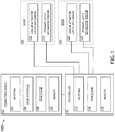
- the vehicle may include at least one vehicle galley (e.g., at least one aircraft galley 200), at least one computing device 102, at least one controller 112, at least one door 120, at least one linear actuator latch mechanism 122, and/or at least one primary latch mechanism sensor 124, some or all of which may be communicatively coupled (e.g., wiredly communicatively coupled or wirelessly communicatively coupled; e.g., directly communicatively coupled and/or communicatively coupled via an intermediate communicatively coupled device) at any given time.
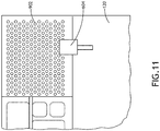
- the vehicle galley may include cabinets and/or vehicle galley inserts (e.g., aircraft galley inserts, such as galley insert ovens or galley insert refrigerators), as well as other components commonly found in galleys.
- Such cabinets may include doors 120 (e.g., cabinet doors), at least one linear actuator latch mechanism 122, and/or at least one primary latch mechanism sensor 124.
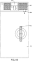
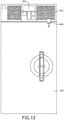
- Each of such vehicle galley inserts may include at least one door 120 (e.g., a vehicle galley insert door, such as an aircraft galley insert door), a housing 902 (as shown in FIG. 9 ), a user interface 904 (as shown in FIG. 9 ), at least one controller 112, at least one door 120, at least one linear actuator latch mechanism 122, and/or at least one primary latch mechanism sensor 124, some or all of which may be communicatively coupled with one or more components of the system.
- the doors 120 may be installed in the vehicle (e.g., the aircraft 100). While the doors are exemplarily described and shown as being aircraft cabinet doors and aircraft galley insert doors, the doors 120 may be any door located within a vehicle (e.g., the aircraft 100). In some embodiments, the door 120 may include a primary latch mechanism 502 (e.g., as shown in FIGS.
- At least one controller 112 at least one linear actuator latch mechanism 122, and/or at least one primary latch mechanism sensor 124; however, in some embodiments, some of such components (e.g., at least one linear actuator latch mechanism 122, at least one controller 112, and/or at least one primary latch mechanism sensor 124) may be installed outside of the door 120 (e.g., in proximity to the door 120).
- the primary latch mechanism sensor 124 may be configured to detect whether the door 120 is in a latched state or an unlatched state and to output state data to the controller 112 and/or the computing device 102. In some embodiments, the primary latch mechanism sensor 124 may be configured to detect whether the door 120 is in an open state or a closed state and to output door state data to the controller 112 and/or the computing device 102.
- the primary latch mechanism 502 may be the primary way in which a user unlatches the door 120 to open the door 120.
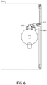
- the primary latch mechanism 502 may include a manual latch actuator 602 that may be manipulated by a user to latch or unlatch the door 120.
- a primary latch mechanism sensor 124 may be configured to detect whether the primary latch mechanism 502 is in a primary latch latched state or a primary latch unlatched state.
- the primary latch mechanism 502 may be (a) installed in or on the door 102 or (b) installed within the vehicle in proximity to the door 120, the primary latch mechanism sensor 124 communicatively coupled to the computing device 102 and/or the controller 112.
- the electronically actuated linear actuator latch mechanism 122 may be (a) installed in or on one of the doors 120 or (b) installed within the vehicle (e.g., the aircraft 100) in proximity to the door 120 (e.g., in a housing 902 of the door 120, as shown in FIG. 10 ), wherein the electronically actuated linear actuator latch mechanism 122 may cause the door 120 to be in a latched state and to cause the door to be in an unlatched state.
- the electronically actuated linear actuator latch mechanism 122 may be a linear solenoid actuator latch mechanism.
- the electronically actuated linear actuator latch mechanism 122 may be or may include a linear actuator (e.g., a linear solenoid 604) configured to extend and retract linearly, based at least on electronic signals received from the controller 112 and/or the computing device 102, such that the linear actuator latch mechanism 122 latches or unlatches the door 120, for example, as shown in FIGS. 6-13 .
- the electronically actuated linear actuator latch mechanism 122 can be actuated manually by hand or electrically via the linear actuator (e.g., a linear solenoid 604).
- the linear actuator e.g., a linear solenoid 604 may also function as a sensor to detect the state of the latch.
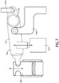
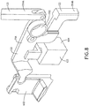
- the electronically actuated linear actuator latch mechanism 122 may also include a pivot 702, a pivot arm 706, a first latch rod 704A, and/or a second latch rod 704B, such as illustrated and described with respect to embodiments depicted in FIGS. 5-9 .
- the pivot arm 706 may pivot about the pivot 702 when the linear actuator (e.g., a linear solenoid 604) extends or retracts.
- a first end of the pivot arm 706 may engage with the manual latch actuator 602.
- a second end of the pivot arm 706 may be coupled to the first latch rod 704A and the second latch rod 704B, such that the first latch rod the first latch rod 704A and the second latch rod 704B latch the door 120 when the linear actuator (e.g., a linear solenoid 604) is in a first state and unlatch the door 120 when the linear actuator (e.g., a linear solenoid 604) is in a second state.
- the linear actuator e.g., a linear solenoid 604
- the electronically actuated linear actuator latch mechanism 122 may be installed outside of the door 120 (e.g., in a housing abutting and/or in proximity to the door 120) such that a rod portion of the electronically actuated linear actuator latch mechanism 122 may engage with the door 120 in the latched state and disengage with the door 120 in the unlatched state.
- the electronically actuated linear actuator latch mechanism 122 may be considered to be a secondary latch mechanism and/or an independent latch mechanism.
- the controller 112 may include at least one antenna 114, at least one processor 116, and/or at least one memory 118, which may be communicatively coupled.
- the at least one processor 116 may be implemented as any suitable type and number of processors.
- the at least one processor 116 may include at least one general purpose processor (e.g., at least one central processing unit (CPU)), at least one digital signal processor (DSP), at least one application specific integrated circuit (ASIC), and/or at least one field-programmable gate array (FPGA).
- the at least one processor 116 may be configured to perform (e.g., collectively perform if more than one processor) any or all of the operations disclosed throughout.
- the processor 116 may be configured to run various software and/or firmware applications and/or computer code stored (e.g., maintained) in a non-transitory computer-readable medium (e.g., memory 118) and configured to execute various instructions or operations.
- the controller 112 may be communicatively coupled (e.g., wiredly communicatively coupled or wirelessly communicatively coupled via the antenna 114) with the computing device 102, the at least one linear actuator latch mechanism 122, and/or the at least one primary latch mechanism sensor 124, at any given time.
- the controller 112 may output data received from the at least one linear actuator latch mechanism 122, and/or the at least one primary latch mechanism sensor 124 to the computing device 102.
- the controller 112 may receive instructions or signals from the computing device 102 and cause one, some, or all of the at least one door 120 to be in latched state or an unlatched state.
- the computing device 102 may include at least one antenna 104, at least one user interface 106, at least one processor 108, and at least one memory 110, which may be communicatively coupled.
- the computing device 102 may be any suitable computing device, such as a vetronics computing device (e.g., an avionics computing device) or a mobile computing device (e.g., a laptop computing device, a phone computing device, and/or a tablet computing device).
- the computing device 102 may be a hand-held computing device used by crew members to check a status of one, some, all of latch/unlatched states of doors 120 in the vehicle and to change one, some, all of latch/unlatched states of doors 120 in the vehicle.
- the at least one processor 108 may be implemented as any suitable type and number of processors.
- the at least one processor 108 may include at least one general purpose processor (e.g., at least one central processing unit (CPU)), at least one digital signal processor (DSP), at least one application specific integrated circuit (ASIC), and/or at least one field-programmable gate array (FPGA).
- the at least one processor 108 may be configured to perform (e.g., collectively perform if more than one processor) any or all of the operations disclosed throughout.
- the processor 108 may be configured to run various software and/or firmware applications and/or computer code stored (e.g., maintained) in a non-transitory computer-readable medium (e.g., memory 110) and configured to execute various instructions or operations.
- the computing device 102 may be communicatively coupled (e.g., wiredly communicatively coupled or wirelessly communicatively coupled via the antenna 104; e.g., directly communicatively coupled and/or communicatively coupled via an intermediate communicatively coupled device) with the controller 112, the at least one linear actuator latch mechanism 122, and/or the at least one primary latch mechanism sensor 124, at any given time.
- the user interface 106 may be and/or may include at least one display, at least one microphone, at least one speaker, at least one vibration, at least one light, at least one button, and/or at least one camera, and the user interface 106 interface may be configured to interface with a user to receive user inputs and to present information to the user.
- the computing device 102 may send and receive data to and from the controller 112, the actuator latch mechanism 122, and/or the at least one primary latch mechanism sensor 124 to the computing device 102.
- the computing device 102 may receive status information from the controller 112, the actuator latch mechanism 122, and/or the at least one primary latch mechanism sensor 124 and output instructions or signals to cause one, some, or all of the at least one linear actuator latch mechanism 122 to be in latched state or an unlatched state.
- the computing device 102 may be configured to: determine whether the door 120 is in the latched state or the unlatched state; and cause the electronically actuated linear actuator latch mechanism 122 to switch from a determined state to a different state of the latched state and the unlatched state (e.g., by controlling the electronically actuated linear actuator latch mechanism 122).
- the computing device 102 may be configured to: present, to a user, information related to the determined state of the door 120; and receive a user input instructing the computing device 102 to cause the electronically actuated linear actuator latch mechanism 122 to switch from the determined state to the different state of the latched state and the unlatched state.
- the computing device 102 may be configured to: present, to the user via the user interface 106, information related to a detected state of the primary latch mechanism 502.
- the computing device 102 may be configured to: obtain vehicle state data from another computing device (e.g., similarly configured to computing device 102) onboard the vehicle; and cause the electronically actuated linear actuator latch mechanism 122 to be in the latched state based at least on the vehicle state data.
- vehicle state data may be aircraft state data
- aircraft state data may be associated with at least one of taxi, takeoff, turbulence, or landing.
- the computing device 102 may be configure to receive status information associated with any number of doors 120.
- a second door 120 may be installed within the vehicle and a second electronically actuated linear actuator latch mechanism 122 may be (a) installed in or on the second door 120 or (b) installed within the vehicle in proximity to the second door 120, wherein the second electronically actuated linear actuator latch mechanism 122 may cause the second door 120 to be in a second latched state and to cause the second door 120 to be in a second unlatched state.
- the computing device 102 may be configured to: determine whether the second electronically actuated linear actuator latch mechanism 122 is in the second latched state or the second unlatched state; and cause the second electronically actuated linear actuator latch mechanism 122 to switch from a second determined state to a different second state of the second latched state and the second unlatched state. In some embodiments, the computing device 102 may be further configured to control a state of the electronically actuated linear actuator latch mechanism 122 independent of controlling a second state of the second electronically actuated linear actuator latch mechanism 122.
- the computing device's 102 causing of the electronically actuated linear actuator latch mechanism 122 to switch from the determined state to the different state of the latched state and the unlatched state may be manually overridable by a user.
- the computing device 102 may be wirelessly communicatively coupled to the electronically actuated linear actuator latch mechanism 122.
- the computing device 102 may be further configured to: cause the electronically actuated linear actuator latch mechanism 122 to be in the unlatched state while the door 120 is open.
- exemplary embodiments of a system including a door 120 e.g., an oven door 120A of the aircraft galley 200 of the aircraft 100
- at least one latch mechanism e.g., a first latch mechanism (e.g., a primary latch mechanism 1402) and/or a secondary latch mechanism 2502) are depicted according to the inventive concepts.
- the primary latch mechanism 1402 may be implemented similarly to the primary latch mechanism 502 of FIGS. 5 and 9-10 in many aspects.
- the primary latch mechanism 1402 may be manually operated by rotation of the door handle 1702 on the front of the oven door 120A.
- the primary latch mechanism 1402 may have multiple positions, such as a latched position, a neutral position, and an unlatched position as shown in FIGS. 14-16 .
- FIG. 14 a portion of the primary latch mechanism 1402 in a latched position is shown.
- FIG. 15 a portion of the primary latch mechanism 1402 in a neutral position is shown.
- FIG. 16 a portion of the primary latch mechanism 1402 in an unlatched position is shown.
- the primary latch mechanism 1402 may automatically move to the neutral state.
- the latch In the neutral state, the latch still may retain the door 120A in the oven because the primary latch mechanism 1402 may not retract far enough by itself.
- the operator may have to force the primary latch mechanism 1402 through the neutral position to fully unlatch the door 120A.
- the purpose of the neutral state may be to protect the operator from the environment in the oven cavity if the primary latch mechanism 1402 is unlatched, either intentionally or unintentionally, and thus prevents the door 120A from completely opening.
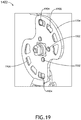
- the primary latch mechanism 1402 may include at least one handle 1702, at least one rotatable plate (e.g., a curve disc 1704), at least one extension rod 2202, at least one compression spring 2204, and/or at least one end piece.
- at least one handle 1702 at least one handle 1702, at least one rotatable plate (e.g., a curve disc 1704), at least one extension rod 2202, at least one compression spring 2204, and/or at least one end piece.
- the handle 1702 may be a lever that an operator actuates to move the primary latch mechanism 1402.
- the handle 1702 may be connected to the curve disc 1704.
- the rotatable plate (e.g., the curve disc 1704) may convert a rotational movement of the handle 1702 to linear movement of the extension rods 2202.
- the rotatable plate may have any suitable shape, such as square, circular, or partially circular.
- the rotatable plate may have at least one (e.g., four) spring plunger 1902 attached to the rotatable plate.
- the spring plungers 1902 may retain the primary latch mechanism 1402 in a neutral or latched position when the primary latch mechanism 1402 is not forced into the unlatched position.
- FIG. 19 shows a handle-side view of the curve disc 1704.
- FIG. 20 shows a non-handle-side view of the curve disc 1704.
- the curve disc 1704 may have a pair of channels 1906 (e.g., recessed channels) for engaging with bearings 1904 of the extension rods 2202 such that the bearings 1904 move through the channels 1906 when the handle 1702 is rotated to move the primary latch mechanism 1402 to a different position.
- the pins 1904 may move through the channels 1906.
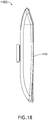
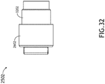
- the extension rods 2202 may extend between the end pieces 2402 and the curve disc 1704.
- the extension rods 2202 may be connected to the end pieces 2402 and may engage with the channels 1906 (e.g., curved channels) of the curve disc 1704.
- the extension rods 2202 may include the bearings 1904 (e.g., roller bearings) that may move through the channels 1906 when the handle 1702 is rotated to move the primary latch mechanism 1402 to a different position.
- the bearings 1904 e.g., roller bearings
- the bearings 1904 may reduce friction during the transfer of energy from rotation to linear.
- the extension rods 2202 may extend through the compression springs 2204.
- the compression springs 2204 may maintain the neutral position of the primary latch mechanism 1402 by accumulating energy when the primary latch mechanism 1402 is placed in the unlatched or latched state and by returning that energy when the primary latch mechanism 1402 is reversed.
- the end pieces 2402 may extend out of the door 120A and may be retained in the oven.
- a tip of the end piece 2402 may include a roller 2406 mounted to the end piece 2402 to reduce friction when the end piece 2402 is extended into the oven.
- the linear movement of the end pieces 2402 may be guided by slide bearings 2404.
- the rollers 2406 may also include a slide bearing to reduce friction.
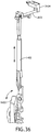
- the secondary latch mechanism 2502 may be implemented similarly to the electronically actuated linear actuator latch mechanism 122 of FIGS. 5-9 in many aspects, except that the secondary latch mechanism 2502 does not need an electronic linear actuator.
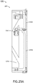
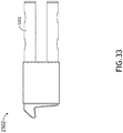
- the secondary latch mechanism 2502 may include a secondary latch button 2706, at least one lever 2708, at least one extension rod 2710, 2712, at least one slide bearing 2602, and/or at least end piece 3202.
- the secondary latch mechanism 1502 may be manually operated by moving the secondary latch button 2706 on the front of the oven door 120A, for example, by moving the secondary latch button 2706 up to an unlatched position or down to a latched position, or vice versa. Movement of the secondary latch button 2706 may be transferred by a lever 2708 to the extension rods 2710, 2712 by the lever 2708 swiveling around a rotation point.
- the extension rods 2710, 2712 may be connected to the lever 2708.
- the extension rods 2710, 2712 may extend into or out of the door 120A depending on movement of the secondary latch button 2706.
- the extension rods 2710, 2712 may be guided by slide bearings 2602 where the extensions rod 2710, 2712 exit the door 120A. Once latched, the end pieces 3202 may be retained by counterparts in the oven frame.
- the state of the secondary latch mechanism 2502 may be maintained by a spring plunger 2704 connected to the lever 2708.
- the spring plunger 2704 may slide over a surface with a defined shape.
- the secondary latch button 2706 may include an indication (e.g., a colored (e.g., red) portion) that shows when the secondary latch mechanism 2502 is in the unlocked position.
- an indication e.g., a colored (e.g., red) portion
- the secondary latch button 2706 may include an indication (e.g., a lock symbol) that shows when the secondary latch mechanism 2502 is in the locked position.
- FIG. 26 a top portion of the secondary latch mechanism 2502 in the locked position is shown.
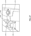
- FIG. 27 a portion of the secondary latch mechanism 2502 in the locked position is shown.
- FIG. 28 a portion of the secondary latch mechanism 2502 in the locked position is shown.
- the secondary latch button 2706 may provide an interface for an operator to manually actuate the second latch mechanism 2502.
- the lever 2708 may rotate around at least one (e.g., two) bearings 3004.
- the spring plunger 2704 may exert pressure on the lever 2708 via an internal spring. If the lever 2708 rotates upward, the spring plunger 2704 may be pushed inward due to a shape of the lever 2708. Once a thickest point is passed, the spring plunger 2704 may move outward. The thickness in the center of the lever 2708 at the spring plunger 2704 may ensure that the secondary latch mechanism is maintained in respective latch states.
- the lever 2708 may include a tip 3002 that engages with an indentation 2702 on the secondary latch button 2706.
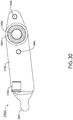
- the extension rods 2710, 2712 may transfer the rotational movement of the lever 2708 into a vertical movement of the end pieces 3202.
- the slide bearings 2602 may provide a load bearing, low friction surface through which the end pieces 3202 are actuated.
- end pieces 3202 may extend into or out of the door 120A to latch or unlatch the secondary latch mechanism 2502.
- the system may include the sensor 3604 and/or at least one sensor pin 3602.
- extension of an end piece 2402 may push the sensor pin 3602 into the sensor 3604, or vice versa. If the primary latch mechanism 1402 is moved into the latched state, the end piece 2402 may move the sensor pin 3602 into the sensor 3604, which may detect if the latched state is achieved and whether the door 120A is closed.
- embodiments of the inventive concepts disclosed herein may be directed to a method and a system including a door having at least one latch mechanism.
- At least one non-transitory computer-readable medium may refer to as at least one non-transitory computer-readable medium (e.g., memory, storage, or a combination thereof; e.g., at least one computer-readable medium implemented as hardware; e.g., at least one non-transitory processor-readable medium, at least one memory (e.g., at least one nonvolatile memory, at least one volatile memory, or a combination thereof; e.g., at least one random-access memory, at least one flash memory, at least one read-only memory (ROM) (e.g., at least one electrically erasable programmable read-only memory (EEPROM)), at least one on-processor memory (e.g., at least one on-processor cache, at least one on-processor buffer, at least one on-processor flash memory, at least one on-processor EEPROM, or a combination thereof), or a combination thereof), at least one storage device
- At least one means one or a plurality of; for example, “at least one” may comprise one, two, three, ..., one hundred, or more.
- one or more means one or a plurality of; for example, “one or more” may comprise one, two, three, ..., one hundred, or more.
- zero or more means zero, one, or a plurality of; for example, “zero or more” may comprise zero, one, two, three, ..., one hundred, or more.
- the methods, operations, and/or functionality disclosed may be implemented as sets of instructions or software readable by a device. Further, it is understood that the specific order or hierarchy of steps in the methods, operations, and/or functionality disclosed are examples of exemplary approaches. Based upon design preferences, it is understood that the specific order or hierarchy of steps in the methods, operations, and/or functionality can be rearranged while remaining within the scope of the inventive concepts disclosed herein.
- the accompanying claims may present elements of the various steps in a sample order, and are not necessarily meant to be limited to the specific order or hierarchy presented.
- embodiments of the methods according to the inventive concepts disclosed herein may include one or more of the steps described herein. Further, such steps may be carried out in any desired order and two or more of the steps may be carried out simultaneously with one another. Two or more of the steps disclosed herein may be combined in a single step, and in some embodiments, one or more of the steps may be carried out as two or more sub-steps. Further, other steps or sub-steps may be carried in addition to, or as substitutes to one or more of the steps disclosed herein.
Landscapes
- Engineering & Computer Science (AREA)
- Mechanical Engineering (AREA)
- Structural Engineering (AREA)
- Aviation & Aerospace Engineering (AREA)
- Chemical & Material Sciences (AREA)
- Combustion & Propulsion (AREA)
- General Engineering & Computer Science (AREA)
- Lock And Its Accessories (AREA)
Applications Claiming Priority (2)
| Application Number | Priority Date | Filing Date | Title |
|---|---|---|---|
| US16/818,076 US20210285256A1 (en) | 2020-03-13 | 2020-03-13 | Linear Actuator Latch Mechanism System for Vehicle |
| US16/925,853 US20210285268A1 (en) | 2020-03-13 | 2020-07-10 | Door Latch Mechanism System for Vehicle |
Publications (2)
| Publication Number | Publication Date |
|---|---|
| EP3878747A1 true EP3878747A1 (fr) | 2021-09-15 |
| EP3878747B1 EP3878747B1 (fr) | 2023-10-11 |
Family
ID=74871335
Family Applications (1)
| Application Number | Title | Priority Date | Filing Date |
|---|---|---|---|
| EP21162630.4A Active EP3878747B1 (fr) | 2020-03-13 | 2021-03-15 | Système de mécanisme de loquet de porte pour véhicule |
Country Status (3)
| Country | Link |
|---|---|
| US (1) | US20210285268A1 (fr) |
| EP (1) | EP3878747B1 (fr) |
| CN (1) | CN113389442B (fr) |
Cited By (2)
| Publication number | Priority date | Publication date | Assignee | Title |
|---|---|---|---|---|
| EP4290036A1 (fr) * | 2022-06-09 | 2023-12-13 | B/E Aerospace, Inc. | Serrure de porte intégrée pour un conteneur de cuisine d'avion |
| EP4368509A1 (fr) * | 2022-11-14 | 2024-05-15 | B/E Aerospace, Inc. | Conteneurs de cuisine d'aéronef |
Families Citing this family (4)
| Publication number | Priority date | Publication date | Assignee | Title |
|---|---|---|---|---|
| US20210285256A1 (en) * | 2020-03-13 | 2021-09-16 | Koninklijke Fabriek Inventum B.V. | Linear Actuator Latch Mechanism System for Vehicle |
| CN113006649B (zh) * | 2021-02-26 | 2024-07-09 | 广东美的厨房电器制造有限公司 | 门体组件及烹饪装置 |
| EP4371881B1 (fr) | 2022-11-18 | 2026-04-15 | B/E Aerospace, Inc. | Mecanisme de verrouillage primaire automatique |
| EP4401051A1 (fr) | 2023-01-11 | 2024-07-17 | B/E Aerospace, Inc. | Serrure de porte biometrique automatique |
Citations (9)
| Publication number | Priority date | Publication date | Assignee | Title |
|---|---|---|---|---|
| GB191310118A (en) * | 1913-04-30 | 1914-03-12 | John Buckingham Ltd | Improved Fastening Means for Pair or Double Doors, particularly applicable to Vehicles. |
| GB398941A (en) * | 1932-04-23 | 1933-09-28 | William Guy Wood | Improvements in fastenings for doors, windows or the like |
| EP0659965A2 (fr) * | 1993-12-21 | 1995-06-28 | Wilhelmus Antonius Stephanus Lokkerbol | Dispositif de fermeture pour portes contre l'ouverture non autorisée en particulier pour des portes de véhicules motorisés |
| US20070200368A1 (en) * | 2005-11-28 | 2007-08-30 | Oshkosh Truck Corporation | Compartment door latch mechanism |
| EP1983131A2 (fr) * | 2007-04-17 | 2008-10-22 | Sell Gmbh | Dispositif de verrouillage d'une porte d'un appareil de réchauffage dans des cuisines d'avions |
| US20110126598A1 (en) * | 2009-11-30 | 2011-06-02 | Bacon Bruce C | Remotely operated locking paddle handle latch assembly for closures and the like |
| EP2796647A1 (fr) * | 2013-04-25 | 2014-10-29 | Steinbach & Vollmann GmbH & Co. KG | Crémone-serrure |
| CA2865344A1 (fr) * | 2014-09-26 | 2016-03-26 | Rousseau Metal Inc. | Systeme de verrouillage de porte, mecanisme de poignee de porte, porte pourvue d'un tel systeme ou mecanisme, kit pour les assembler, et methodes d'assemblage et d'operation correspondantes |
| WO2019129437A1 (fr) * | 2017-12-26 | 2019-07-04 | Arcelik Anonim Sirketi | Appareil approprié pour être utilisé dans des aéronefs |
Family Cites Families (6)
| Publication number | Priority date | Publication date | Assignee | Title |
|---|---|---|---|---|
| CN201605906U (zh) * | 2010-01-11 | 2010-10-13 | 希美克(广州)实业有限公司 | 平开式门窗把手锁 |
| AU2013202689B2 (en) * | 2013-02-20 | 2016-09-15 | D & D Technologies Pty Ltd | Latching Assembly |
| ES2744649T3 (es) * | 2015-05-13 | 2020-02-25 | Dormakaba Deutschland Gmbh | Cerradura |
| US11525289B2 (en) * | 2017-07-17 | 2022-12-13 | Magna Closures Inc. | Vehicular closure latch assembly with roller-type latch mechanism and cinch mechanism |
| CN108252572B (zh) * | 2018-03-13 | 2023-07-28 | 杭州易欣安实业有限公司 | 插芯锁 |
| CN109826502B (zh) * | 2019-01-17 | 2021-04-09 | 宁波生久柜锁有限公司 | 通装型光交箱智能锁 |
-
2020
- 2020-07-10 US US16/925,853 patent/US20210285268A1/en not_active Abandoned
-
2021
- 2021-03-15 EP EP21162630.4A patent/EP3878747B1/fr active Active
- 2021-03-15 CN CN202110274226.0A patent/CN113389442B/zh active Active
Patent Citations (9)
| Publication number | Priority date | Publication date | Assignee | Title |
|---|---|---|---|---|
| GB191310118A (en) * | 1913-04-30 | 1914-03-12 | John Buckingham Ltd | Improved Fastening Means for Pair or Double Doors, particularly applicable to Vehicles. |
| GB398941A (en) * | 1932-04-23 | 1933-09-28 | William Guy Wood | Improvements in fastenings for doors, windows or the like |
| EP0659965A2 (fr) * | 1993-12-21 | 1995-06-28 | Wilhelmus Antonius Stephanus Lokkerbol | Dispositif de fermeture pour portes contre l'ouverture non autorisée en particulier pour des portes de véhicules motorisés |
| US20070200368A1 (en) * | 2005-11-28 | 2007-08-30 | Oshkosh Truck Corporation | Compartment door latch mechanism |
| EP1983131A2 (fr) * | 2007-04-17 | 2008-10-22 | Sell Gmbh | Dispositif de verrouillage d'une porte d'un appareil de réchauffage dans des cuisines d'avions |
| US20110126598A1 (en) * | 2009-11-30 | 2011-06-02 | Bacon Bruce C | Remotely operated locking paddle handle latch assembly for closures and the like |
| EP2796647A1 (fr) * | 2013-04-25 | 2014-10-29 | Steinbach & Vollmann GmbH & Co. KG | Crémone-serrure |
| CA2865344A1 (fr) * | 2014-09-26 | 2016-03-26 | Rousseau Metal Inc. | Systeme de verrouillage de porte, mecanisme de poignee de porte, porte pourvue d'un tel systeme ou mecanisme, kit pour les assembler, et methodes d'assemblage et d'operation correspondantes |
| WO2019129437A1 (fr) * | 2017-12-26 | 2019-07-04 | Arcelik Anonim Sirketi | Appareil approprié pour être utilisé dans des aéronefs |
Cited By (5)
| Publication number | Priority date | Publication date | Assignee | Title |
|---|---|---|---|---|
| EP4290036A1 (fr) * | 2022-06-09 | 2023-12-13 | B/E Aerospace, Inc. | Serrure de porte intégrée pour un conteneur de cuisine d'avion |
| EP4289732A1 (fr) * | 2022-06-09 | 2023-12-13 | B/E Aerospace, Inc. | Procédé et système pour le fonctionnement de dispositifs de sécurité de conteneurs de cuisine d'aéronef |
| US12371165B2 (en) | 2022-06-09 | 2025-07-29 | B/E Aerospace, Inc. | Integrated door lock for an aircraft galley container |
| US12466563B2 (en) | 2022-06-09 | 2025-11-11 | B/E Aerospace, Inc. | Method and system for operation of safety features of aircraft galley containers |
| EP4368509A1 (fr) * | 2022-11-14 | 2024-05-15 | B/E Aerospace, Inc. | Conteneurs de cuisine d'aéronef |
Also Published As
| Publication number | Publication date |
|---|---|
| EP3878747B1 (fr) | 2023-10-11 |
| CN113389442B (zh) | 2023-08-11 |
| CN113389442A (zh) | 2021-09-14 |
| US20210285268A1 (en) | 2021-09-16 |
Similar Documents
| Publication | Publication Date | Title |
|---|---|---|
| EP3878747B1 (fr) | Système de mécanisme de loquet de porte pour véhicule | |
| US10661719B2 (en) | Vehicle interior componet | |
| US10619378B2 (en) | Lock with movable knob | |
| US11305860B2 (en) | Aircraft privacy door and door frame assembly | |
| US9334046B2 (en) | Device for maneuvering, on the ground, a door of an aircraft landing gear | |
| EP3345825B1 (fr) | Système de verrouillage avec maintien de position | |
| US10087664B2 (en) | Device for operating at least one aircraft door comprising a control handle | |
| US10647430B2 (en) | Overhead storage bin latch system | |
| CN111295310B (zh) | 车辆内部组件 | |
| US11242149B2 (en) | Moveable T-divider for meal cart stowage | |
| US11773619B2 (en) | Door lock system for an appliance | |
| CN114555464A (zh) | 设有保持检测装置的上位锁 | |
| US2653070A (en) | Filing cabinet locking controls | |
| CN114585561A (zh) | 设有保持检测装置的上位锁 | |
| US11572194B2 (en) | Aircraft door latch assembly | |
| EP3878733B1 (fr) | Système de mécanisme de verrouillage à actionneur linéaire pour véhicule | |
| US20240167692A1 (en) | Automatic primary latch mechanism | |
| US20240151079A1 (en) | Handle for a vehicle door | |
| CN119585636A (zh) | 用于提供机动车辆的车辆访问功能的传感器系统 | |
| US11318892B2 (en) | Vehicle interior component | |
| EP3784566B1 (fr) | Procédé et agencement de verrouillage pour verrouillage sécurisé d'un premier corps à un second corps au niveau d'un véhicule aérien | |
| CN217812898U (zh) | 一种舱门锁保险机构及载人航空器 | |
| EP3656954B1 (fr) | Ensemble poignée de porte de véhicule |
Legal Events
| Date | Code | Title | Description |
|---|---|---|---|
| PUAI | Public reference made under article 153(3) epc to a published international application that has entered the european phase |
Free format text: ORIGINAL CODE: 0009012 |
|
| STAA | Information on the status of an ep patent application or granted ep patent |
Free format text: STATUS: THE APPLICATION HAS BEEN PUBLISHED |
|
| AK | Designated contracting states |
Kind code of ref document: A1 Designated state(s): AL AT BE BG CH CY CZ DE DK EE ES FI FR GB GR HR HU IE IS IT LI LT LU LV MC MK MT NL NO PL PT RO RS SE SI SK SM TR |
|
| STAA | Information on the status of an ep patent application or granted ep patent |
Free format text: STATUS: REQUEST FOR EXAMINATION WAS MADE |
|
| 17P | Request for examination filed |
Effective date: 20220315 |
|
| RBV | Designated contracting states (corrected) |
Designated state(s): AL AT BE BG CH CY CZ DE DK EE ES FI FR GB GR HR HU IE IS IT LI LT LU LV MC MK MT NL NO PL PT RO RS SE SI SK SM TR |
|
| GRAP | Despatch of communication of intention to grant a patent |
Free format text: ORIGINAL CODE: EPIDOSNIGR1 |
|
| STAA | Information on the status of an ep patent application or granted ep patent |
Free format text: STATUS: GRANT OF PATENT IS INTENDED |
|
| INTG | Intention to grant announced |
Effective date: 20230512 |
|
| GRAS | Grant fee paid |
Free format text: ORIGINAL CODE: EPIDOSNIGR3 |
|
| GRAA | (expected) grant |
Free format text: ORIGINAL CODE: 0009210 |
|
| STAA | Information on the status of an ep patent application or granted ep patent |
Free format text: STATUS: THE PATENT HAS BEEN GRANTED |
|
| AK | Designated contracting states |
Kind code of ref document: B1 Designated state(s): AL AT BE BG CH CY CZ DE DK EE ES FI FR GB GR HR HU IE IS IT LI LT LU LV MC MK MT NL NO PL PT RO RS SE SI SK SM TR |
|
| REG | Reference to a national code |
Ref country code: GB Ref legal event code: FG4D |
|
| REG | Reference to a national code |
Ref country code: CH Ref legal event code: EP |
|
| REG | Reference to a national code |
Ref country code: NL Ref legal event code: FP |
|
| REG | Reference to a national code |
Ref country code: DE Ref legal event code: R096 Ref document number: 602021005718 Country of ref document: DE |
|
| REG | Reference to a national code |
Ref country code: IE Ref legal event code: FG4D |
|
| REG | Reference to a national code |
Ref country code: LT Ref legal event code: MG9D |
|
| REG | Reference to a national code |
Ref country code: AT Ref legal event code: MK05 Ref document number: 1620002 Country of ref document: AT Kind code of ref document: T Effective date: 20231011 |
|
| PG25 | Lapsed in a contracting state [announced via postgrant information from national office to epo] |
Ref country code: GR Free format text: LAPSE BECAUSE OF FAILURE TO SUBMIT A TRANSLATION OF THE DESCRIPTION OR TO PAY THE FEE WITHIN THE PRESCRIBED TIME-LIMIT Effective date: 20240112 |
|
| PG25 | Lapsed in a contracting state [announced via postgrant information from national office to epo] |
Ref country code: IS Free format text: LAPSE BECAUSE OF FAILURE TO SUBMIT A TRANSLATION OF THE DESCRIPTION OR TO PAY THE FEE WITHIN THE PRESCRIBED TIME-LIMIT Effective date: 20240211 |
|
| PG25 | Lapsed in a contracting state [announced via postgrant information from national office to epo] |
Ref country code: LT Free format text: LAPSE BECAUSE OF FAILURE TO SUBMIT A TRANSLATION OF THE DESCRIPTION OR TO PAY THE FEE WITHIN THE PRESCRIBED TIME-LIMIT Effective date: 20231011 |
|
| PG25 | Lapsed in a contracting state [announced via postgrant information from national office to epo] |
Ref country code: AT Free format text: LAPSE BECAUSE OF FAILURE TO SUBMIT A TRANSLATION OF THE DESCRIPTION OR TO PAY THE FEE WITHIN THE PRESCRIBED TIME-LIMIT Effective date: 20231011 |
|
| PG25 | Lapsed in a contracting state [announced via postgrant information from national office to epo] |
Ref country code: ES Free format text: LAPSE BECAUSE OF FAILURE TO SUBMIT A TRANSLATION OF THE DESCRIPTION OR TO PAY THE FEE WITHIN THE PRESCRIBED TIME-LIMIT Effective date: 20231011 |
|
| PG25 | Lapsed in a contracting state [announced via postgrant information from national office to epo] |
Ref country code: LT Free format text: LAPSE BECAUSE OF FAILURE TO SUBMIT A TRANSLATION OF THE DESCRIPTION OR TO PAY THE FEE WITHIN THE PRESCRIBED TIME-LIMIT Effective date: 20231011 Ref country code: IS Free format text: LAPSE BECAUSE OF FAILURE TO SUBMIT A TRANSLATION OF THE DESCRIPTION OR TO PAY THE FEE WITHIN THE PRESCRIBED TIME-LIMIT Effective date: 20240211 Ref country code: GR Free format text: LAPSE BECAUSE OF FAILURE TO SUBMIT A TRANSLATION OF THE DESCRIPTION OR TO PAY THE FEE WITHIN THE PRESCRIBED TIME-LIMIT Effective date: 20240112 Ref country code: ES Free format text: LAPSE BECAUSE OF FAILURE TO SUBMIT A TRANSLATION OF THE DESCRIPTION OR TO PAY THE FEE WITHIN THE PRESCRIBED TIME-LIMIT Effective date: 20231011 Ref country code: BG Free format text: LAPSE BECAUSE OF FAILURE TO SUBMIT A TRANSLATION OF THE DESCRIPTION OR TO PAY THE FEE WITHIN THE PRESCRIBED TIME-LIMIT Effective date: 20240111 Ref country code: AT Free format text: LAPSE BECAUSE OF FAILURE TO SUBMIT A TRANSLATION OF THE DESCRIPTION OR TO PAY THE FEE WITHIN THE PRESCRIBED TIME-LIMIT Effective date: 20231011 Ref country code: PT Free format text: LAPSE BECAUSE OF FAILURE TO SUBMIT A TRANSLATION OF THE DESCRIPTION OR TO PAY THE FEE WITHIN THE PRESCRIBED TIME-LIMIT Effective date: 20240212 |
|
| PG25 | Lapsed in a contracting state [announced via postgrant information from national office to epo] |
Ref country code: SE Free format text: LAPSE BECAUSE OF FAILURE TO SUBMIT A TRANSLATION OF THE DESCRIPTION OR TO PAY THE FEE WITHIN THE PRESCRIBED TIME-LIMIT Effective date: 20231011 Ref country code: RS Free format text: LAPSE BECAUSE OF FAILURE TO SUBMIT A TRANSLATION OF THE DESCRIPTION OR TO PAY THE FEE WITHIN THE PRESCRIBED TIME-LIMIT Effective date: 20231011 Ref country code: PL Free format text: LAPSE BECAUSE OF FAILURE TO SUBMIT A TRANSLATION OF THE DESCRIPTION OR TO PAY THE FEE WITHIN THE PRESCRIBED TIME-LIMIT Effective date: 20231011 Ref country code: NO Free format text: LAPSE BECAUSE OF FAILURE TO SUBMIT A TRANSLATION OF THE DESCRIPTION OR TO PAY THE FEE WITHIN THE PRESCRIBED TIME-LIMIT Effective date: 20240111 Ref country code: LV Free format text: LAPSE BECAUSE OF FAILURE TO SUBMIT A TRANSLATION OF THE DESCRIPTION OR TO PAY THE FEE WITHIN THE PRESCRIBED TIME-LIMIT Effective date: 20231011 Ref country code: HR Free format text: LAPSE BECAUSE OF FAILURE TO SUBMIT A TRANSLATION OF THE DESCRIPTION OR TO PAY THE FEE WITHIN THE PRESCRIBED TIME-LIMIT Effective date: 20231011 |
|
| PG25 | Lapsed in a contracting state [announced via postgrant information from national office to epo] |
Ref country code: DK Free format text: LAPSE BECAUSE OF FAILURE TO SUBMIT A TRANSLATION OF THE DESCRIPTION OR TO PAY THE FEE WITHIN THE PRESCRIBED TIME-LIMIT Effective date: 20231011 |
|
| REG | Reference to a national code |
Ref country code: DE Ref legal event code: R097 Ref document number: 602021005718 Country of ref document: DE |
|
| PG25 | Lapsed in a contracting state [announced via postgrant information from national office to epo] |
Ref country code: CZ Free format text: LAPSE BECAUSE OF FAILURE TO SUBMIT A TRANSLATION OF THE DESCRIPTION OR TO PAY THE FEE WITHIN THE PRESCRIBED TIME-LIMIT Effective date: 20231011 |
|
| PG25 | Lapsed in a contracting state [announced via postgrant information from national office to epo] |
Ref country code: SK Free format text: LAPSE BECAUSE OF FAILURE TO SUBMIT A TRANSLATION OF THE DESCRIPTION OR TO PAY THE FEE WITHIN THE PRESCRIBED TIME-LIMIT Effective date: 20231011 |
|
| PG25 | Lapsed in a contracting state [announced via postgrant information from national office to epo] |
Ref country code: SM Free format text: LAPSE BECAUSE OF FAILURE TO SUBMIT A TRANSLATION OF THE DESCRIPTION OR TO PAY THE FEE WITHIN THE PRESCRIBED TIME-LIMIT Effective date: 20231011 Ref country code: SK Free format text: LAPSE BECAUSE OF FAILURE TO SUBMIT A TRANSLATION OF THE DESCRIPTION OR TO PAY THE FEE WITHIN THE PRESCRIBED TIME-LIMIT Effective date: 20231011 Ref country code: RO Free format text: LAPSE BECAUSE OF FAILURE TO SUBMIT A TRANSLATION OF THE DESCRIPTION OR TO PAY THE FEE WITHIN THE PRESCRIBED TIME-LIMIT Effective date: 20231011 Ref country code: IT Free format text: LAPSE BECAUSE OF FAILURE TO SUBMIT A TRANSLATION OF THE DESCRIPTION OR TO PAY THE FEE WITHIN THE PRESCRIBED TIME-LIMIT Effective date: 20231011 Ref country code: EE Free format text: LAPSE BECAUSE OF FAILURE TO SUBMIT A TRANSLATION OF THE DESCRIPTION OR TO PAY THE FEE WITHIN THE PRESCRIBED TIME-LIMIT Effective date: 20231011 Ref country code: DK Free format text: LAPSE BECAUSE OF FAILURE TO SUBMIT A TRANSLATION OF THE DESCRIPTION OR TO PAY THE FEE WITHIN THE PRESCRIBED TIME-LIMIT Effective date: 20231011 Ref country code: CZ Free format text: LAPSE BECAUSE OF FAILURE TO SUBMIT A TRANSLATION OF THE DESCRIPTION OR TO PAY THE FEE WITHIN THE PRESCRIBED TIME-LIMIT Effective date: 20231011 |
|
| PLBE | No opposition filed within time limit |
Free format text: ORIGINAL CODE: 0009261 |
|
| STAA | Information on the status of an ep patent application or granted ep patent |
Free format text: STATUS: NO OPPOSITION FILED WITHIN TIME LIMIT |
|
| 26N | No opposition filed |
Effective date: 20240712 |
|
| PG25 | Lapsed in a contracting state [announced via postgrant information from national office to epo] |
Ref country code: SI Free format text: LAPSE BECAUSE OF FAILURE TO SUBMIT A TRANSLATION OF THE DESCRIPTION OR TO PAY THE FEE WITHIN THE PRESCRIBED TIME-LIMIT Effective date: 20231011 |
|
| PG25 | Lapsed in a contracting state [announced via postgrant information from national office to epo] |
Ref country code: SI Free format text: LAPSE BECAUSE OF FAILURE TO SUBMIT A TRANSLATION OF THE DESCRIPTION OR TO PAY THE FEE WITHIN THE PRESCRIBED TIME-LIMIT Effective date: 20231011 |
|
| REG | Reference to a national code |
Ref country code: CH Ref legal event code: PL |
|
| PG25 | Lapsed in a contracting state [announced via postgrant information from national office to epo] |
Ref country code: LU Free format text: LAPSE BECAUSE OF NON-PAYMENT OF DUE FEES Effective date: 20240315 |
|
| PG25 | Lapsed in a contracting state [announced via postgrant information from national office to epo] |
Ref country code: MC Free format text: LAPSE BECAUSE OF FAILURE TO SUBMIT A TRANSLATION OF THE DESCRIPTION OR TO PAY THE FEE WITHIN THE PRESCRIBED TIME-LIMIT Effective date: 20231011 |
|
| PG25 | Lapsed in a contracting state [announced via postgrant information from national office to epo] |
Ref country code: MC Free format text: LAPSE BECAUSE OF FAILURE TO SUBMIT A TRANSLATION OF THE DESCRIPTION OR TO PAY THE FEE WITHIN THE PRESCRIBED TIME-LIMIT Effective date: 20231011 Ref country code: LU Free format text: LAPSE BECAUSE OF NON-PAYMENT OF DUE FEES Effective date: 20240315 |
|
| REG | Reference to a national code |
Ref country code: BE Ref legal event code: MM Effective date: 20240331 |
|
| PG25 | Lapsed in a contracting state [announced via postgrant information from national office to epo] |
Ref country code: BE Free format text: LAPSE BECAUSE OF NON-PAYMENT OF DUE FEES Effective date: 20240331 |
|
| PG25 | Lapsed in a contracting state [announced via postgrant information from national office to epo] |
Ref country code: IE Free format text: LAPSE BECAUSE OF NON-PAYMENT OF DUE FEES Effective date: 20240315 |
|
| PG25 | Lapsed in a contracting state [announced via postgrant information from national office to epo] |
Ref country code: IE Free format text: LAPSE BECAUSE OF NON-PAYMENT OF DUE FEES Effective date: 20240315 Ref country code: BE Free format text: LAPSE BECAUSE OF NON-PAYMENT OF DUE FEES Effective date: 20240331 Ref country code: CH Free format text: LAPSE BECAUSE OF NON-PAYMENT OF DUE FEES Effective date: 20240331 |
|
| PG25 | Lapsed in a contracting state [announced via postgrant information from national office to epo] |
Ref country code: CY Free format text: LAPSE BECAUSE OF FAILURE TO SUBMIT A TRANSLATION OF THE DESCRIPTION OR TO PAY THE FEE WITHIN THE PRESCRIBED TIME-LIMIT; INVALID AB INITIO Effective date: 20210315 |
|
| PG25 | Lapsed in a contracting state [announced via postgrant information from national office to epo] |
Ref country code: HU Free format text: LAPSE BECAUSE OF FAILURE TO SUBMIT A TRANSLATION OF THE DESCRIPTION OR TO PAY THE FEE WITHIN THE PRESCRIBED TIME-LIMIT; INVALID AB INITIO Effective date: 20210315 |
|
| PG25 | Lapsed in a contracting state [announced via postgrant information from national office to epo] |
Ref country code: FI Free format text: LAPSE BECAUSE OF FAILURE TO SUBMIT A TRANSLATION OF THE DESCRIPTION OR TO PAY THE FEE WITHIN THE PRESCRIBED TIME-LIMIT Effective date: 20231011 |
|
| PG25 | Lapsed in a contracting state [announced via postgrant information from national office to epo] |
Ref country code: TR Free format text: LAPSE BECAUSE OF FAILURE TO SUBMIT A TRANSLATION OF THE DESCRIPTION OR TO PAY THE FEE WITHIN THE PRESCRIBED TIME-LIMIT Effective date: 20231011 |
|
| P01 | Opt-out of the competence of the unified patent court (upc) registered |
Free format text: CASE NUMBER: UPC_APP_0018668_3878747/2025 Effective date: 20251221 |
|
| PGFP | Annual fee paid to national office [announced via postgrant information from national office to epo] |
Ref country code: NL Payment date: 20260219 Year of fee payment: 6 |
|
| PGFP | Annual fee paid to national office [announced via postgrant information from national office to epo] |
Ref country code: GB Payment date: 20260219 Year of fee payment: 6 |
|
| PGFP | Annual fee paid to national office [announced via postgrant information from national office to epo] |
Ref country code: DE Payment date: 20260219 Year of fee payment: 6 |
|
| PGFP | Annual fee paid to national office [announced via postgrant information from national office to epo] |
Ref country code: FR Payment date: 20260220 Year of fee payment: 6 |