EP3878748B1 - Fahrzeugkabinenluftzufuhrvorrichtung und betriebsverfahren solch einer vorrichtung - Google Patents
Fahrzeugkabinenluftzufuhrvorrichtung und betriebsverfahren solch einer vorrichtung Download PDFInfo
- Publication number
- EP3878748B1 EP3878748B1 EP20382180.6A EP20382180A EP3878748B1 EP 3878748 B1 EP3878748 B1 EP 3878748B1 EP 20382180 A EP20382180 A EP 20382180A EP 3878748 B1 EP3878748 B1 EP 3878748B1
- Authority
- EP
- European Patent Office
- Prior art keywords
- air
- exhaust
- cabin
- supply device
- fresh air
- Prior art date
- Legal status (The legal status is an assumption and is not a legal conclusion. Google has not performed a legal analysis and makes no representation as to the accuracy of the status listed.)
- Active
Links
Images
Classifications
-
- B—PERFORMING OPERATIONS; TRANSPORTING
- B64—AIRCRAFT; AVIATION; COSMONAUTICS
- B64D—EQUIPMENT FOR FITTING IN OR TO AIRCRAFT; FLIGHT SUITS; PARACHUTES; ARRANGEMENT OR MOUNTING OF POWER PLANTS OR PROPULSION TRANSMISSIONS IN AIRCRAFT
- B64D13/00—Arrangements or adaptations of air-treatment apparatus for aircraft crew or passengers, or freight space
- B64D13/02—Arrangements or adaptations of air-treatment apparatus for aircraft crew or passengers, or freight space the air being pressurised
-
- B—PERFORMING OPERATIONS; TRANSPORTING
- B64—AIRCRAFT; AVIATION; COSMONAUTICS
- B64D—EQUIPMENT FOR FITTING IN OR TO AIRCRAFT; FLIGHT SUITS; PARACHUTES; ARRANGEMENT OR MOUNTING OF POWER PLANTS OR PROPULSION TRANSMISSIONS IN AIRCRAFT
- B64D13/00—Arrangements or adaptations of air-treatment apparatus for aircraft crew or passengers, or freight space
- B64D13/06—Arrangements or adaptations of air-treatment apparatus for aircraft crew or passengers, or freight space the air being conditioned
-
- B—PERFORMING OPERATIONS; TRANSPORTING
- B64—AIRCRAFT; AVIATION; COSMONAUTICS
- B64D—EQUIPMENT FOR FITTING IN OR TO AIRCRAFT; FLIGHT SUITS; PARACHUTES; ARRANGEMENT OR MOUNTING OF POWER PLANTS OR PROPULSION TRANSMISSIONS IN AIRCRAFT
- B64D13/00—Arrangements or adaptations of air-treatment apparatus for aircraft crew or passengers, or freight space
- B64D13/06—Arrangements or adaptations of air-treatment apparatus for aircraft crew or passengers, or freight space the air being conditioned
- B64D2013/0603—Environmental Control Systems
- B64D2013/0611—Environmental Control Systems combined with auxiliary power units (APU's)
-
- B—PERFORMING OPERATIONS; TRANSPORTING
- B64—AIRCRAFT; AVIATION; COSMONAUTICS
- B64D—EQUIPMENT FOR FITTING IN OR TO AIRCRAFT; FLIGHT SUITS; PARACHUTES; ARRANGEMENT OR MOUNTING OF POWER PLANTS OR PROPULSION TRANSMISSIONS IN AIRCRAFT
- B64D13/00—Arrangements or adaptations of air-treatment apparatus for aircraft crew or passengers, or freight space
- B64D13/06—Arrangements or adaptations of air-treatment apparatus for aircraft crew or passengers, or freight space the air being conditioned
- B64D2013/0603—Environmental Control Systems
- B64D2013/0651—Environmental Control Systems comprising filters, e.g. dust filters
Definitions
- the invention relates to a vehicle cabin air supply device according to claim 7 and an operating method of such device according to claim 1. More particularly the invention relates to an aircraft cabin air supply device.
- the invention relates to the supply of fresh air to a vehicle cabin such as an aircraft cabin, while minimizing the contaminants and bad odor levels in said cabin.
- Air supplied into vehicles' cabins is often contaminated by machinery between an exterior fresh air intake and a cabin's interior volume. Indeed in circuits between an air intake and an air mouth in a vehicle cabin, dust may accumulate, oil may leak from some machinery, bearings, gears, etc. These contaminants contaminate the fresh air and are injected into the vehicle's cabin. Such contaminants create unpleasant odors for passengers in the cabin.
- EP1621243 discloses an air conditioning unit with a water extractor unit.
- the unit consists of a passage with a vortex generator surrounded by a wall an aperture to an outer water trap with water sump.
- the separator chamber is a multi-stage cascade unit. The first stage accumulates water droplets, while the second stage promotes release of the accumulated droplets. The third stage draws off air mass flow.
- US5725048 discloses a device for cooling drive components and for controlling a temperature inside a passenger compartment of a motor vehicle, comprising a cooling circuit through which a coolant is circulated, a refrigerant circuit including a condenser and an evaporator; and an air-guide duct through which an air current is circulated to exchange heat with said cooling circuit and said refrigerant circuit, said air-guide duct extending from an outflow opening of the passenger compartment to an intake-air opening thereof, said air-guide duct including an inflow air-current control element for mixing the air current from said passenger compartment with a fresh air flow, a heat exchanger, disposed downstream of said inflow air-current control element, for transferring heat from said coolant to the mixed air current, an outflow air-current control element for dividing the mixed air current into an air component introduced into the passenger compartment and an exhaust air component drawn off into the environment, and a bypass duct having a first end disposed upstream of the inflow air-current control element and a second end connected to said out
- US2018147514 discloses a motor vehicle having a water tank with a first inner chamber for separating and conducting away water from a first air flow flowing through the first inner chamber.
- the water tank is designed as a heat exchanger, comprising a heat exchanger element for transferring thermal energy between the first air flow and a second air flow.
- WO2018189487 discloses a system comprising an air intake outside the cabin, a filter and a turbine for supplying the cabin with pressurized air.
- the air intake is used to supply the engine of the vehicle with air; the system comprising an air intake duct connected directly to the air delivery duct extending between the air filter of the engine of the vehicle and the motor.
- the invention aims to provide an air supply device and method that supply clean air to a vehicle's cabin.
- the invention proposes a device and method that are simple to manufacture and to retrofit on existing vehicles.
- the invention proposes an economical solution to provide clean air in a cabin.
- the invention proposes an operating method of a vehicle cabin air supply device comprising:
- fresh air is used for air taken outside the cabin as opposite to air already present in the cabin.
- the “fresh air” may be processed or modified compared to its natural state in the atmosphere before being taken in through an air intake of the invention.
- the air may for example be filtered, compressed, heated, etc.. This may particularly be the case if the air has gone through compressor stage of a turbine.
- air extracted from a compressor stage of a turbine engine air is often called “bleed air” as it is bled from a stage of the engine stage.
- the air supply device may reflect different situations, depending on the air supply device configuration.
- the air supply device may comprise a dedicated circulation device that is switched on upon request for fresh air in the vehicle cabin.
- the air supply device may make use of an existing circulation device on-board the vehicle, for example a circulation device ensuring another on-board function, or a turbine compressor stage on an aircraft.
- the starting of the air supply device may correspond to the opening of a valve, of vanes, or of a door onto an air tap to the air source provided by the circulation device.
- starting the air supply device may correspond to the opening of a valve (or door, or tap, or vane, etc.) to supply fresh air into a fresh air circuit comprising at least one air mouth into the cabin.
- said fresh air is exhausted outside the cabin.
- the fresh air channeled to the exhaust is not entering the cabin.
- the exhaust is adapted to exhaust the fresh air in the atmosphere, back in a machine such as a turbine, or in the exhaust of another machine such as a turbine exhaust.
- the invention proposes a method that avoids to inject contaminants in the cabin upon starting the air supply device. Nonetheless, in some specific embodiments, part of the fresh air may be simultaneously injected in the cabin to ensure minimum air renewal in the cabin.
- the fresh air is injected into the cabin.
- most of the volatile contaminants are present in the air stored in the air circuit before starting the air supply device, most air contaminants are not injected in the cabin, and ejected outside the cabin instead. Any contaminant that would be in the first stream of air circulating in the air circuit is thus not injected into the cabin, thereby reducing the amount of contaminants and sources of unpleasant odors.
- the air circuit between the air intake and the air exhaust may be at least partially cleared of accumulated contaminant, at least of volatized contaminants.
- Liquid or solid contaminants accumulated on machinery and surfaces of the air supply device may also be volatized and/or ejected when a stream of fresh air is first introduced in the air circuit. Thanks to a method according to the invention, such contaminants are also ejected outside the cabin. After the exhaust duration, the air circuit of an air supply device according to the invention is much cleaner than before it is started, such that the fresh air afterwards introduced in the cabin contains no or a low amount of contaminants and bad odor generating particles.
- the fresh air is entirely diverted to an exhaust during an exhaust duration.
- said fresh air may at least partially be circulated in an air circuit.
- the air circuit beneficially comprises at least part of a cabin air supply circuit in which said fresh air circulates when it is injected in said cabin.
- the circulation of the fresh air in the air circuit and its ejection through an exhaust allows to remove pollutants from said air circuit.
- the common portion of air circuit between an air intake and an air mouth for injecting said fresh air into the cabin and air circuit between said air intake and the exhaust for ejecting said fresh air may be maximized in order to ensure a cleaning of the longest possible portion of air circuit during the exhaust duration and before the fresh air is injected into the cabin.
- Said exhaust duration may be predetermined.
- the exhaust duration may be determined based on different factors. For example it may be determined based on a nominal air flow upon starting the air supply device, and an amount of air stored in the air circuit of the air device.
- a threshold may be arbitrarily defined to determine the exhaust duration, such as for example at least one and a half the volume of the air circuit must be ejected through the air exhaust during the exhaust duration.
- the exhaust duration may also be determined based on test results. For example a determined amount of contaminant may be placed in an air circuit of the air supply device and the amount of contaminants may be measured to determine when a contaminant concentration is below a predetermined threshold.
- the exhaust duration value may be stored in a memory.
- the air supply device may comprise a memory to store such value.
- the exhaust duration may be calculated depending on determined criteria such as air flow, contaminants presence, air pressure, air humidity, etc. the exhaust duration may nonetheless have a minimum threshold value.
- Said exhaust duration may depend on data received from a contaminant sensor.
- Said contaminant sensor is adapted to sense the presence of at least one air contaminant.
- air contaminants may be hydrocarbons, oil, anti-fluids, particles, droplets, dust, etc ..
- the contaminant sensor is beneficially placed in an air circuit between the air intake and the air exhaust.
- the exhaust duration may thus be adapted depending on the amount of contaminant in the air circulating in the air circuit upon starting the air supply device.
- An air flow control device may receive contaminant data from said contaminant sensor and be adapted to process such data.
- the air flow control device may determine an exhaust duration at least based on the contaminant data.
- the fresh air may be bled from an engine compressor stage.
- air for being injecting in an aircraft cabin may be bled from an aircraft main or secondary engine compressor stage.
- the fresh air may be drawn by a dedicated air circulation device.
- the air supply system may have its own dedicated air circulation device to draw fresh air from outside the vehicle's cabin. Such air circulation device may nonetheless be powered by an engine having at least one other function such as propulsion or electrical power generation.
- the air circulation device may for example be a dedicated air compressor.
- the compressor may have its own power source such as an electrical engine, or may be clutchable to a main or secondary aircraft engine.
- the invention also extends to a vehicle air supply device comprising:
- the fresh air intake is beneficially placed upstream from the air exhaust according to a usual direction of displacement of the vehicle.
- the air supply device also comprises an air circuit for conducting fresh air between the air intake and the air mouth(s), as well as between the air intake and the air exhaust.
- the air flow control device is adapted to:
- the air flow control device is adapted to implement an operation method of a vehicle cabin air supply device according to the invention.
- the air flow control device may be adapted to divert fresh air from the air intake to the air exhaust upon starting a circulation device such as a fan, or upon opening an air tap onto a pressurized fresh air source, such as a turbine compressor stage for example.
- the air flow control device may also be adapted to stop the fresh air from passing through the one or more air mouth to a cabin.
- a device according to the invention may further comprise a cabin valve between the air intake and the air mouth.
- the air flow control device is adapted to control the cabin valve.
- the air flow control device may partially or fully close the cabin valve during the exhaust duration.
- the cabin valve is beneficially fully closed during the exhaust duration. After the exhaust duration, the cabin valve may at least partially be open, and may beneficially be fully open.
- a device according to the invention may further comprise an exhaust valve between the air intake and the exhaust.
- the air supply device may comprise an exhaust valve between the air intake and the air exhaust.
- the air flow control device is adapted to control the exhaust valve.
- the exhaust valve is open during the exhaust duration. After the exhaust duration, the exhaust valve may at least partially be closed, and may beneficially be fully closed.
- the air supply device may comprise inlet guide vanes between the air intake and the air mouth.
- the inlet guide vanes are beneficially placed in an upstream portion of an air circuit of the air supply device.
- the inlet guide vanes may beneficially be controlled between a closed position and an open position.
- the air flow control device may control the inlet guide vanes. The intake of fresh air in the air circuit may thus be controlled.
- the inlet guide vanes may be directly upstream an air compressor for circulating air in the air circuit.
- the opening of the inlet guide vanes and/or the activating an air circulation device may be considered at the starting of the air supply device. After opening the inlet guide vanes and/or activating an air circulation device, the fresh air is exhausted through the air exhaust during an exhaust duration.
- the invention also extends to an aircraft comprising an air supply device according to an embodiment according to the invention.
- the invention also extends to other possible combinations of features described in the above description and in the following description relative to the figures.
- the invention extends to an air supply device comprising features described in relation to the operating method; the invention extends to an operating method comprising features described in relation to the air supply device; the invention extends to aircrafts comprising features described in relation to the air supply device and/or the operating method.
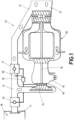
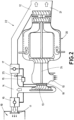
- the air supply device 22 comprises an air intake 10 for drawing fresh air from outside the vehicle, an air mouth 11 for injecting said fresh air into a cabin 19, and an air exhaust 12 for ejecting said fresh air towards outside the cabin, beneficially to an exterior of the vehicle, through an engine exhaust nozzle 21.
- the air supply device 22 also comprises an air circuit 14 between the air intake 10 and the air exhaust 12 and the air mouth 11.
- the air supply device 22 further comprises a cabin valve 16 placed in the air circuit 14 between the air intake 10 and the cabin air mouth 11.
- the cabin valve 16 may be closed to impede a flow of fresh air between the air intake 10 and the air mouth 11, or open to let air flow from the air intake 10 to the air mouth 11.
- the air supply device 22 also comprises an exhaust valve 17 placed in the air circuit 14 between the air intake 10 and the air exhaust 12.
- the exhaust valve 17 may be closed to impede a flow of fresh air between the air intake 10 and the air exhaust 12, or open to let air flow from the air intake 10 to the air exhaust 12.
- the cabin valve 16 and the exhaust valve 17 may be electrically controlled.
- the air supply device 22 comprises an air flow control device 15.
- the air flow control device 15 is adapted to control the cabin valve 16 and the exhaust valve 17.
- the air supply device 22 also comprises an air circulation device.
- the air circulation device comprises a dedicated load compressor 13 for circulating air from the air intake 10 to the air mouth 11 and/or to the air exhaust 12.
- the compressor 13 may be clutchable to an engine shaft 24 of an engine 20.
- the compressor may thus be switched on or off by clutching its shaft to the engine's shaft 24.
- the start of the compressor may trigger the start of the exhaust duration.
- the engine 20 may ensure additional functions such as propulsion or electrical power generation.
- the engine 20 may for example be an auxiliary power unit of an aircraft.
- the air supply device 22 represented in the figures 1 and 2 also comprises inlet guide vanes 18.
- the inlet guide vanes 18 are placed upstream from the compressor 13.
- the inlet guide vanes 18 may be controlled by the air flow control device 15.
- the inlet guide vanes 18 may be closed when no fresh air is requested in the cabin.
- the inlet guide vanes aperture may correspond to the start of the air supply device from which an exhaust duration is triggered.
- the air supply device 22 may also comprise a contaminant sensor 25.
- the contaminant sensor 25 may be placed in a portion of the air circuit 14 between the air intake 10 and the air exhaust 12, in which fresh air circulates during the exhaust duration. Thus the amount of air contaminant in the air exhausted through the air exhaust 12 may be measured.
- the exhaust duration may be interrupted upon detection of a concentration of contaminants below a predetermined level.
- the contaminant sensor 25 may be connected to the flow control device 15 so as to supply its data to the flow control device 15.
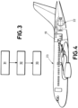
- Figure 3 represents a method of operation an air supply device 22 according to the invention.
- the air supply device 22 is started.
- the exhaust duration is triggered.
- a second step 32 the fresh air drawn from outside the vehicle is exhausted after having circulated in the air circuit 14, without having been injected into the cabin 19 at any moment.
- the air flow control device 15 is adapted to open the exhaust valve 17 and close the cabin valve 16 during the exhaust duration.
- the fresh air drawn through the air intake 10 is thus exhausted through the exhaust 12 after having circulated in the air circuit 14, as represented by arrows on figure 1 .
- the fresh air thus cleans the air circuit 14 of any accumulated contaminant such as dust, oil and other volatile components that are susceptible to create bad odor sensation.
- a third step 33 the fresh air is injected into the cabin 19.
- the air flow control device 15 closes the exhaust valve 17 and opens the cabin valve 16 such that clean fresh air drawn from outside the vehicle may be injected into the cabin 19 through one or more air mouth(s) 11.
- the flow of air in such configuration is shown by arrows in figure 2 .
- the flow control device 15 may be a controller or a computer.
- the air flow control device 15 may comprise a memory to store an exhaust duration value and/or an algorithm to determine the exhaust duration.
- the air flow control device 15 may receive contaminant data from the contaminant sensor 25 to determine an exhaust duration.
- the exhaust duration may be determined based on tests, taking into account that in configurations similar to that presented in figures 1 and 2 , the highest amount of contaminants is present in the first portion of the air circuit 14.
- the flow control device 15 may operate other functions such as a control of the engine 20.
- the flow control device 15 may be connected to a central computer or to a control board for pilots or flight attendants, such that that fresh air may be delivered in the cabin upon request.
- an aircraft 23 according to the invention is represented, which comprises a cabin 19 and a cabin air supply device 22 according to the invention.
- the air supply device 22 may be powered by an auxiliary power unit (APU) of the aircraft.
- APU auxiliary power unit
Landscapes
- Health & Medical Sciences (AREA)
- General Health & Medical Sciences (AREA)
- Pulmonology (AREA)
- Engineering & Computer Science (AREA)
- Aviation & Aerospace Engineering (AREA)
- Air-Conditioning For Vehicles (AREA)
Claims (11)
- Betriebsverfahren einer Fahrzeugkabinenluftzufuhrvorrichtung, umfassend:- Aufnehmen von Frischluft von außerhalb der Kabine,- Einleiten der Frischluft in die Kabine (19),dadurch gekennzeichnet, dass diese einen Schritt umfasst, bei dem beim Starten der Luftzufuhrvorrichtung (22) die Frischluft vollständig zu einer Luftabführung (12) umgeleitet wird, wobei die Frischluft während einer bestimmten Abführdauer nach außerhalb der Kabine abgeführt wird, bevor die Frischluft in die Kabine eingeleitet wird.
- Verfahren nach Anspruch 1,
ferner dadurch gekennzeichnet, dass während der Abführdauer die Frischluft zumindest teilweise in einem Luftkreislauf (14) umgewälzt wird. - Verfahren nach einem der Ansprüche 1 bis 2, ferner dadurch gekennzeichnet, dass die Abführdauer vorbestimmt ist.
- Verfahren nach einem der Ansprüche 1 bis 2, ferner dadurch gekennzeichnet, dass die Abführdauer von Daten abhängt, die aus einem Schadstoffsensor (25) empfangen werden.
- Verfahren nach einem der Ansprüche 1 bis 4, ferner dadurch gekennzeichnet, dass die Frischluft aus einer Verdichterstufe des Triebwerks abgezapft wird.
- Verfahren nach einem der Ansprüche 1 bis 4, ferner dadurch gekennzeichnet, dass die Frischluft durch eine speziell dafür vorgesehene Luftumwälzvorrichtung angesaugt wird.
- Fahrzeugluftzufuhrvorrichtung (22), umfassend:- einen Frischlufteinlass (10),- eine Luftöffnung (11), die dazu eingerichtet ist, Luft in eine Fahrzeugkabine (19) einzuleiten,- eine Luftumwälzvorrichtung (13), die dazu ausgelegt ist, Frischluft aus dem Lufteinlass (10) zur Luftöffnung (11) umzuwälzen,dadurch gekennzeichnet, dass diese ferner umfasst:- eine Luftabführung (12) zum Abführen von Frischluft aus der Kabine (19) nach außen,- eine Luftstromsteuervorrichtung (15), die dazu eingerichtet ist:∘ die Frischluft vollständig zur Luftabführung (12) umzuleiten.∘ beim Starten der Luftzufuhrvorrichtung während einer Abführdauer Frischluft aus dem Lufteinlass zur Luftabführung umzuleiten.
- Vorrichtung nach Anspruch 7, ferner dadurch gekennzeichnet, dass diese ein Kabinenventil zwischen dem Lufteinlass und der Luftöffnung umfasst.
- Vorrichtung nach einem der Ansprüche 7 oder 8, ferner dadurch gekennzeichnet, dass diese ein Abführventil zwischen dem Lufteinlass und der Luftabführung umfasst.
- Vorrichtung nach einem der Ansprüche 7 bis 9, ferner dadurch gekennzeichnet, dass diese Einlassleitschaufeln zwischen dem Lufteinlass und der Luftöffnung umfasst.
- Flugzeug (23), umfassend eine Luftzufuhrvorrichtung (22) nach einem der Ansprüche 7 bis 10.
Priority Applications (3)
| Application Number | Priority Date | Filing Date | Title |
|---|---|---|---|
| EP20382180.6A EP3878748B1 (de) | 2020-03-12 | 2020-03-12 | Fahrzeugkabinenluftzufuhrvorrichtung und betriebsverfahren solch einer vorrichtung |
| ES20382180T ES3009767T3 (en) | 2020-03-12 | 2020-03-12 | Vehicle cabin air supply device and operating method of such device |
| US17/188,115 US11772800B2 (en) | 2020-03-12 | 2021-03-01 | Vehicle cabin air supply device and operating method of such device |
Applications Claiming Priority (1)
| Application Number | Priority Date | Filing Date | Title |
|---|---|---|---|
| EP20382180.6A EP3878748B1 (de) | 2020-03-12 | 2020-03-12 | Fahrzeugkabinenluftzufuhrvorrichtung und betriebsverfahren solch einer vorrichtung |
Publications (2)
| Publication Number | Publication Date |
|---|---|
| EP3878748A1 EP3878748A1 (de) | 2021-09-15 |
| EP3878748B1 true EP3878748B1 (de) | 2024-12-18 |
Family
ID=69810770
Family Applications (1)
| Application Number | Title | Priority Date | Filing Date |
|---|---|---|---|
| EP20382180.6A Active EP3878748B1 (de) | 2020-03-12 | 2020-03-12 | Fahrzeugkabinenluftzufuhrvorrichtung und betriebsverfahren solch einer vorrichtung |
Country Status (3)
| Country | Link |
|---|---|
| US (1) | US11772800B2 (de) |
| EP (1) | EP3878748B1 (de) |
| ES (1) | ES3009767T3 (de) |
Families Citing this family (1)
| Publication number | Priority date | Publication date | Assignee | Title |
|---|---|---|---|---|
| US12012217B2 (en) * | 2022-08-22 | 2024-06-18 | Gulfstream Aerospace Corporation | Auxiliary power unit air inlet door with specified acoustic reflecting and/or diffusing characteristics |
Citations (1)
| Publication number | Priority date | Publication date | Assignee | Title |
|---|---|---|---|---|
| US20190160416A1 (en) * | 2017-11-30 | 2019-05-30 | Honda Motor Co., Ltd. | Air purification device for vehicle |
Family Cites Families (17)
| Publication number | Priority date | Publication date | Assignee | Title |
|---|---|---|---|---|
| DE3509767A1 (de) * | 1984-03-31 | 1986-01-02 | Deutsche Airbus GmbH, 8000 München | Verfahren und einrichtung fuer die energie- und klimafrischlufterzeugung von flugzeugen |
| US5086622A (en) * | 1990-08-17 | 1992-02-11 | United Technologies Corporation | Environmental control system condensing cycle |
| ES2062837T3 (es) * | 1991-03-19 | 1994-12-16 | Behr Gmbh & Co | Procedimiento para la refrigeracion de componentes de propulsion y para la calefaccion de un habitaculo de un automovil, en particular de un automovil electrico e instalacion para la realizacion de dicho procedimiento. |
| US5634964A (en) * | 1995-02-13 | 1997-06-03 | United Technologies Corporation | Air mixer with water separator |
| DE19509773C1 (de) * | 1995-03-17 | 1996-06-27 | Daimler Benz Aerospace Airbus | Belüftungssystem zur Verminderung der Konzentration von Verunreinigungen im Flugzeugpassagierbereich |
| DE102004036568A1 (de) | 2004-07-28 | 2006-02-16 | Liebherr-Aerospace Lindenberg Gmbh | Wasserabscheider für Klimaanlagen |
| US9914336B2 (en) * | 2010-06-24 | 2018-03-13 | Ford Global Technologies, Llc | Electric compartment cooling apparatus and method |
| US9744829B2 (en) * | 2014-09-23 | 2017-08-29 | Mahle International Gmbh | Vehicle HVAC system with cabin ventilation while parked |
| EP2905158B8 (de) * | 2015-04-24 | 2018-08-22 | Weidplas GmbH | Kraftfahrzeug mit einem als wärmetauscher ausgebildeten wasserkasten |
| US10035602B2 (en) * | 2015-06-08 | 2018-07-31 | Hamilton Sundstrand Corporation | No primary heat exchanger and bleed air (cabin discharge air) assist |
| GB201513952D0 (en) * | 2015-08-07 | 2015-09-23 | Rolls Royce Plc | Aircraft pneumatic system |
| DE102016223528B4 (de) * | 2016-11-28 | 2025-06-12 | Airbus Operations Gmbh | Kabinenabluftunterstützt betreibbare Flugzeugklimaanlage mit einem elektrisch angetriebenen Umgebungsluftkompressor |
| US10384785B2 (en) * | 2017-02-17 | 2019-08-20 | Hamilton Sundstrand Corporation | Two mode system that provides bleed and outside air or just outside air |
| FR3065185B1 (fr) * | 2017-04-14 | 2019-07-05 | Eliatis | Systeme de pressurisation de la cabine d'un engin travaillant dans un air charge de particules |
| US10954865B2 (en) * | 2018-06-19 | 2021-03-23 | The Boeing Company | Pressurized air systems for aircraft and related methods |
| US20200217326A1 (en) * | 2019-01-03 | 2020-07-09 | Hamilton Sundstrand Corporation | Concentric turbine condensing cycle |
| US20200255152A1 (en) * | 2019-02-08 | 2020-08-13 | Hamilton Sundstrand Corporation | Environmental control systems and methods of controlling air flow through environmental control systems |
-
2020
- 2020-03-12 EP EP20382180.6A patent/EP3878748B1/de active Active
- 2020-03-12 ES ES20382180T patent/ES3009767T3/es active Active
-
2021
- 2021-03-01 US US17/188,115 patent/US11772800B2/en active Active
Patent Citations (1)
| Publication number | Priority date | Publication date | Assignee | Title |
|---|---|---|---|---|
| US20190160416A1 (en) * | 2017-11-30 | 2019-05-30 | Honda Motor Co., Ltd. | Air purification device for vehicle |
Also Published As
| Publication number | Publication date |
|---|---|
| ES3009767T3 (en) | 2025-03-31 |
| US11772800B2 (en) | 2023-10-03 |
| US20210284344A1 (en) | 2021-09-16 |
| EP3878748A1 (de) | 2021-09-15 |
Similar Documents
| Publication | Publication Date | Title |
|---|---|---|
| RU2434788C2 (ru) | Система подачи воздуха для воздушного судна и способ смешивания двух потоков воздуха в такой системе | |
| CN107226212B (zh) | 具有电驱动环境空气压缩机的飞机空调系统及其操作方法 | |
| US20080110185A1 (en) | Vehicle HVAC system | |
| US9849753B2 (en) | Heating system for an automotive vehicle | |
| EP1188666B1 (de) | Ein Klimatisierungssystem für Flugzeuge und Verfahren | |
| CN101511618B (zh) | 车用冷却风扇控制系统和车用冷却风扇的控制方法 | |
| EP3173337B1 (de) | Flugzeugklimatisierungssystem mit umgebungsluftzufuhr und verfahren zum betrieb solch eines flugzeugklimatisierungssystems | |
| US10640938B2 (en) | Suction excavator with flow reversal and method for controlling same | |
| CN103303125B (zh) | 电动车辆高电压设备冷却系统及冷却方法 | |
| EP3878748B1 (de) | Fahrzeugkabinenluftzufuhrvorrichtung und betriebsverfahren solch einer vorrichtung | |
| US6655163B1 (en) | Dual evaporator air conditioning system and method of use | |
| TW201411067A (zh) | 空氣壓縮裝置 | |
| JP2000059917A (ja) | 電動車両搭載電池温度調整装置 | |
| GB2343164A (en) | Cooling an electronic control unit in a vehicle | |
| US20240262170A1 (en) | Air-conditioning system with electrostatic filter, motor vehicle having such an air-conditioning system, and method for operating such an air-conditioning system | |
| FR3070315A1 (fr) | Vehicule equipe d’un groupe de climatisation et procede de climatisation | |
| KR101187897B1 (ko) | 화생방 방호 및 냉난방 통합 장치 | |
| KR0185825B1 (ko) | 자동차용 내장형 공기청정기 | |
| US20260116140A1 (en) | Hvac system for removal of moisture of air flowing therethrough | |
| KR100581788B1 (ko) | 하이브리드 차량의 밧데리 쿨링장치 | |
| JP2007335286A (ja) | 燃料電池の空気供給システム | |
| JP2020516519A (ja) | 2つのダクトを備える換気、暖房、及び/又は、空調設備 | |
| KR20250061940A (ko) | 차량용 공조 장치 | |
| JP2022170420A (ja) | 車両 | |
| CN110678341A (zh) | 包括附加空气入口的通风、供暖和/或空调设备 |
Legal Events
| Date | Code | Title | Description |
|---|---|---|---|
| PUAI | Public reference made under article 153(3) epc to a published international application that has entered the european phase |
Free format text: ORIGINAL CODE: 0009012 |
|
| STAA | Information on the status of an ep patent application or granted ep patent |
Free format text: STATUS: THE APPLICATION HAS BEEN PUBLISHED |
|
| AK | Designated contracting states |
Kind code of ref document: A1 Designated state(s): AL AT BE BG CH CY CZ DE DK EE ES FI FR GB GR HR HU IE IS IT LI LT LU LV MC MK MT NL NO PL PT RO RS SE SI SK SM TR |
|
| STAA | Information on the status of an ep patent application or granted ep patent |
Free format text: STATUS: REQUEST FOR EXAMINATION WAS MADE |
|
| 17P | Request for examination filed |
Effective date: 20220308 |
|
| RBV | Designated contracting states (corrected) |
Designated state(s): AL AT BE BG CH CY CZ DE DK EE ES FI FR GB GR HR HU IE IS IT LI LT LU LV MC MK MT NL NO PL PT RO RS SE SI SK SM TR |
|
| STAA | Information on the status of an ep patent application or granted ep patent |
Free format text: STATUS: EXAMINATION IS IN PROGRESS |
|
| 17Q | First examination report despatched |
Effective date: 20230426 |
|
| GRAP | Despatch of communication of intention to grant a patent |
Free format text: ORIGINAL CODE: EPIDOSNIGR1 |
|
| STAA | Information on the status of an ep patent application or granted ep patent |
Free format text: STATUS: GRANT OF PATENT IS INTENDED |
|
| INTG | Intention to grant announced |
Effective date: 20240723 |
|
| GRAS | Grant fee paid |
Free format text: ORIGINAL CODE: EPIDOSNIGR3 |
|
| GRAA | (expected) grant |
Free format text: ORIGINAL CODE: 0009210 |
|
| STAA | Information on the status of an ep patent application or granted ep patent |
Free format text: STATUS: THE PATENT HAS BEEN GRANTED |
|
| AK | Designated contracting states |
Kind code of ref document: B1 Designated state(s): AL AT BE BG CH CY CZ DE DK EE ES FI FR GB GR HR HU IE IS IT LI LT LU LV MC MK MT NL NO PL PT RO RS SE SI SK SM TR |
|
| REG | Reference to a national code |
Ref country code: CH Ref legal event code: EP |
|
| REG | Reference to a national code |
Ref country code: DE Ref legal event code: R096 Ref document number: 602020043291 Country of ref document: DE |
|
| REG | Reference to a national code |
Ref country code: IE Ref legal event code: FG4D |
|
| REG | Reference to a national code |
Ref country code: ES Ref legal event code: FG2A Ref document number: 3009767 Country of ref document: ES Kind code of ref document: T3 Effective date: 20250331 |
|
| REG | Reference to a national code |
Ref country code: LT Ref legal event code: MG9D |
|
| PG25 | Lapsed in a contracting state [announced via postgrant information from national office to epo] |
Ref country code: HR Free format text: LAPSE BECAUSE OF FAILURE TO SUBMIT A TRANSLATION OF THE DESCRIPTION OR TO PAY THE FEE WITHIN THE PRESCRIBED TIME-LIMIT Effective date: 20241218 |
|
| PG25 | Lapsed in a contracting state [announced via postgrant information from national office to epo] |
Ref country code: FI Free format text: LAPSE BECAUSE OF FAILURE TO SUBMIT A TRANSLATION OF THE DESCRIPTION OR TO PAY THE FEE WITHIN THE PRESCRIBED TIME-LIMIT Effective date: 20241218 |
|
| PG25 | Lapsed in a contracting state [announced via postgrant information from national office to epo] |
Ref country code: BG Free format text: LAPSE BECAUSE OF FAILURE TO SUBMIT A TRANSLATION OF THE DESCRIPTION OR TO PAY THE FEE WITHIN THE PRESCRIBED TIME-LIMIT Effective date: 20241218 |
|
| PG25 | Lapsed in a contracting state [announced via postgrant information from national office to epo] |
Ref country code: NO Free format text: LAPSE BECAUSE OF FAILURE TO SUBMIT A TRANSLATION OF THE DESCRIPTION OR TO PAY THE FEE WITHIN THE PRESCRIBED TIME-LIMIT Effective date: 20250318 |
|
| REG | Reference to a national code |
Ref country code: NL Ref legal event code: MP Effective date: 20241218 |
|
| PG25 | Lapsed in a contracting state [announced via postgrant information from national office to epo] |
Ref country code: LV Free format text: LAPSE BECAUSE OF FAILURE TO SUBMIT A TRANSLATION OF THE DESCRIPTION OR TO PAY THE FEE WITHIN THE PRESCRIBED TIME-LIMIT Effective date: 20241218 |
|
| PG25 | Lapsed in a contracting state [announced via postgrant information from national office to epo] |
Ref country code: RS Free format text: LAPSE BECAUSE OF FAILURE TO SUBMIT A TRANSLATION OF THE DESCRIPTION OR TO PAY THE FEE WITHIN THE PRESCRIBED TIME-LIMIT Effective date: 20250318 |
|
| PG25 | Lapsed in a contracting state [announced via postgrant information from national office to epo] |
Ref country code: NL Free format text: LAPSE BECAUSE OF FAILURE TO SUBMIT A TRANSLATION OF THE DESCRIPTION OR TO PAY THE FEE WITHIN THE PRESCRIBED TIME-LIMIT Effective date: 20241218 |
|
| REG | Reference to a national code |
Ref country code: AT Ref legal event code: MK05 Ref document number: 1752067 Country of ref document: AT Kind code of ref document: T Effective date: 20241218 |
|
| PG25 | Lapsed in a contracting state [announced via postgrant information from national office to epo] |
Ref country code: SM Free format text: LAPSE BECAUSE OF FAILURE TO SUBMIT A TRANSLATION OF THE DESCRIPTION OR TO PAY THE FEE WITHIN THE PRESCRIBED TIME-LIMIT Effective date: 20241218 |
|
| PG25 | Lapsed in a contracting state [announced via postgrant information from national office to epo] |
Ref country code: PL Free format text: LAPSE BECAUSE OF FAILURE TO SUBMIT A TRANSLATION OF THE DESCRIPTION OR TO PAY THE FEE WITHIN THE PRESCRIBED TIME-LIMIT Effective date: 20241218 |
|
| PGFP | Annual fee paid to national office [announced via postgrant information from national office to epo] |
Ref country code: ES Payment date: 20250429 Year of fee payment: 6 |
|
| PG25 | Lapsed in a contracting state [announced via postgrant information from national office to epo] |
Ref country code: IS Free format text: LAPSE BECAUSE OF FAILURE TO SUBMIT A TRANSLATION OF THE DESCRIPTION OR TO PAY THE FEE WITHIN THE PRESCRIBED TIME-LIMIT Effective date: 20250418 |
|
| PG25 | Lapsed in a contracting state [announced via postgrant information from national office to epo] |
Ref country code: PT Free format text: LAPSE BECAUSE OF FAILURE TO SUBMIT A TRANSLATION OF THE DESCRIPTION OR TO PAY THE FEE WITHIN THE PRESCRIBED TIME-LIMIT Effective date: 20250421 |
|
| PG25 | Lapsed in a contracting state [announced via postgrant information from national office to epo] |
Ref country code: EE Free format text: LAPSE BECAUSE OF FAILURE TO SUBMIT A TRANSLATION OF THE DESCRIPTION OR TO PAY THE FEE WITHIN THE PRESCRIBED TIME-LIMIT Effective date: 20241218 |
|
| PG25 | Lapsed in a contracting state [announced via postgrant information from national office to epo] |
Ref country code: RO Free format text: LAPSE BECAUSE OF FAILURE TO SUBMIT A TRANSLATION OF THE DESCRIPTION OR TO PAY THE FEE WITHIN THE PRESCRIBED TIME-LIMIT Effective date: 20241218 Ref country code: AT Free format text: LAPSE BECAUSE OF FAILURE TO SUBMIT A TRANSLATION OF THE DESCRIPTION OR TO PAY THE FEE WITHIN THE PRESCRIBED TIME-LIMIT Effective date: 20241218 |
|
| PG25 | Lapsed in a contracting state [announced via postgrant information from national office to epo] |
Ref country code: SK Free format text: LAPSE BECAUSE OF FAILURE TO SUBMIT A TRANSLATION OF THE DESCRIPTION OR TO PAY THE FEE WITHIN THE PRESCRIBED TIME-LIMIT Effective date: 20241218 |
|
| PG25 | Lapsed in a contracting state [announced via postgrant information from national office to epo] |
Ref country code: CZ Free format text: LAPSE BECAUSE OF FAILURE TO SUBMIT A TRANSLATION OF THE DESCRIPTION OR TO PAY THE FEE WITHIN THE PRESCRIBED TIME-LIMIT Effective date: 20241218 |
|
| PG25 | Lapsed in a contracting state [announced via postgrant information from national office to epo] |
Ref country code: IT Free format text: LAPSE BECAUSE OF FAILURE TO SUBMIT A TRANSLATION OF THE DESCRIPTION OR TO PAY THE FEE WITHIN THE PRESCRIBED TIME-LIMIT Effective date: 20241218 |
|
| PG25 | Lapsed in a contracting state [announced via postgrant information from national office to epo] |
Ref country code: SE Free format text: LAPSE BECAUSE OF FAILURE TO SUBMIT A TRANSLATION OF THE DESCRIPTION OR TO PAY THE FEE WITHIN THE PRESCRIBED TIME-LIMIT Effective date: 20241218 |
|
| REG | Reference to a national code |
Ref country code: DE Ref legal event code: R097 Ref document number: 602020043291 Country of ref document: DE |
|
| PG25 | Lapsed in a contracting state [announced via postgrant information from national office to epo] |
Ref country code: DK Free format text: LAPSE BECAUSE OF FAILURE TO SUBMIT A TRANSLATION OF THE DESCRIPTION OR TO PAY THE FEE WITHIN THE PRESCRIBED TIME-LIMIT Effective date: 20241218 |
|
| PG25 | Lapsed in a contracting state [announced via postgrant information from national office to epo] |
Ref country code: MC Free format text: LAPSE BECAUSE OF FAILURE TO SUBMIT A TRANSLATION OF THE DESCRIPTION OR TO PAY THE FEE WITHIN THE PRESCRIBED TIME-LIMIT Effective date: 20241218 |
|
| REG | Reference to a national code |
Ref country code: CH Ref legal event code: H13 Free format text: ST27 STATUS EVENT CODE: U-0-0-H10-H13 (AS PROVIDED BY THE NATIONAL OFFICE) Effective date: 20251023 |
|
| PLBE | No opposition filed within time limit |
Free format text: ORIGINAL CODE: 0009261 |
|
| STAA | Information on the status of an ep patent application or granted ep patent |
Free format text: STATUS: NO OPPOSITION FILED WITHIN TIME LIMIT |
|
| PG25 | Lapsed in a contracting state [announced via postgrant information from national office to epo] |
Ref country code: LU Free format text: LAPSE BECAUSE OF NON-PAYMENT OF DUE FEES Effective date: 20250312 |
|
| 26N | No opposition filed |
Effective date: 20250919 |
|
| REG | Reference to a national code |
Ref country code: BE Ref legal event code: MM Effective date: 20250331 |
|
| PG25 | Lapsed in a contracting state [announced via postgrant information from national office to epo] |
Ref country code: BE Free format text: LAPSE BECAUSE OF NON-PAYMENT OF DUE FEES Effective date: 20250331 |
|
| PG25 | Lapsed in a contracting state [announced via postgrant information from national office to epo] |
Ref country code: CH Free format text: LAPSE BECAUSE OF NON-PAYMENT OF DUE FEES Effective date: 20250331 |
|
| PG25 | Lapsed in a contracting state [announced via postgrant information from national office to epo] |
Ref country code: IE Free format text: LAPSE BECAUSE OF NON-PAYMENT OF DUE FEES Effective date: 20250312 |
|
| PGFP | Annual fee paid to national office [announced via postgrant information from national office to epo] |
Ref country code: GB Payment date: 20260324 Year of fee payment: 7 |
|
| PGFP | Annual fee paid to national office [announced via postgrant information from national office to epo] |
Ref country code: DE Payment date: 20260319 Year of fee payment: 7 |
|
| PGFP | Annual fee paid to national office [announced via postgrant information from national office to epo] |
Ref country code: FR Payment date: 20260323 Year of fee payment: 7 |