EP3878793B1 - Überwachungssysteme für personenförderer - Google Patents
Überwachungssysteme für personenförderer Download PDFInfo
- Publication number
- EP3878793B1 EP3878793B1 EP20161811.3A EP20161811A EP3878793B1 EP 3878793 B1 EP3878793 B1 EP 3878793B1 EP 20161811 A EP20161811 A EP 20161811A EP 3878793 B1 EP3878793 B1 EP 3878793B1
- Authority
- EP
- European Patent Office
- Prior art keywords
- acceleration sensor
- passenger conveyor
- region
- acceleration
- gravity vector
- Prior art date
- Legal status (The legal status is an assumption and is not a legal conclusion. Google has not performed a legal analysis and makes no representation as to the accuracy of the status listed.)
- Active
Links
Images





Classifications
-
- B—PERFORMING OPERATIONS; TRANSPORTING
- B66—HOISTING; LIFTING; HAULING
- B66B—ELEVATORS; ESCALATORS OR MOVING WALKWAYS
- B66B27/00—Indicating operating conditions of escalators or moving walkways
-
- B—PERFORMING OPERATIONS; TRANSPORTING
- B66—HOISTING; LIFTING; HAULING
- B66B—ELEVATORS; ESCALATORS OR MOVING WALKWAYS
- B66B25/00—Control of escalators or moving walkways
- B66B25/006—Monitoring for maintenance or repair
-
- B—PERFORMING OPERATIONS; TRANSPORTING
- B66—HOISTING; LIFTING; HAULING
- B66B—ELEVATORS; ESCALATORS OR MOVING WALKWAYS
- B66B29/00—Safety devices of escalators or moving walkways
- B66B29/005—Applications of security monitors
-
- B—PERFORMING OPERATIONS; TRANSPORTING
- B66—HOISTING; LIFTING; HAULING
- B66B—ELEVATORS; ESCALATORS OR MOVING WALKWAYS
- B66B21/00—Kinds or types of escalators or moving walkways
- B66B21/02—Escalators
-
- B—PERFORMING OPERATIONS; TRANSPORTING
- B66—HOISTING; LIFTING; HAULING
- B66B—ELEVATORS; ESCALATORS OR MOVING WALKWAYS
- B66B23/00—Component parts of escalators or moving walkways
- B66B23/02—Driving gear
-
- B—PERFORMING OPERATIONS; TRANSPORTING
- B66—HOISTING; LIFTING; HAULING
- B66B—ELEVATORS; ESCALATORS OR MOVING WALKWAYS
- B66B23/00—Component parts of escalators or moving walkways
- B66B23/02—Driving gear
- B66B23/04—Driving gear for handrails
-
- B—PERFORMING OPERATIONS; TRANSPORTING
- B66—HOISTING; LIFTING; HAULING
- B66B—ELEVATORS; ESCALATORS OR MOVING WALKWAYS
- B66B23/00—Component parts of escalators or moving walkways
- B66B23/08—Carrying surfaces
- B66B23/12—Steps
-
- B—PERFORMING OPERATIONS; TRANSPORTING
- B66—HOISTING; LIFTING; HAULING
- B66B—ELEVATORS; ESCALATORS OR MOVING WALKWAYS
- B66B25/00—Control of escalators or moving walkways
-
- B—PERFORMING OPERATIONS; TRANSPORTING
- B66—HOISTING; LIFTING; HAULING
- B66B—ELEVATORS; ESCALATORS OR MOVING WALKWAYS
- B66B29/00—Safety devices of escalators or moving walkways
Definitions
- This invention relates to monitoring systems for passenger conveyors, such as escalators or moving walkways, and methods for monitoring passenger conveyors.
- Conventional passenger conveyors such as escalators and moving walkways, generally comprise a transportation band, on which passengers stand, which is propelled by a drive system to convey the passengers from one place to another place, for example between floors of a building or along extended distances.
- the transportation band comprises a plurality of conveyance elements, such as steps or pallets, which are drivingly coupled to at least one drive member, such as a drive belt.
- the drive belt moves along a conveyance path, around a first turnaround portion, returns inside a balustrade (or associated support structure) following a return path and then around a second turnaround portion.
- a drive pulley, driven by a drive motor, is generally provided at one of the turnaround portions to drive the drive belt.
- Escalators transport passengers between a lower landing region and an upper landing region.
- Escalators typically comprise an endless transportation band formed from a plurality of mutually connected step bodies.
- the transportation band is mounted on a drive belt or chain belt, which is driven about an upper reversal point at the upper landing region and a lower reversal point at the lower landing region.
- Moving walkways transport passengers between a first landing region and a second landing region.
- Moving walkways are typically pallet type moving walkways, which include a continuous series of pallets joined together to form a transportation band.
- Inclined moving walkways transport passengers over a vertical distance between a first/lower landing region and an upper/second landing region. Moving walkways can transport passengers over extended distances, and inclined sections can be provided within extended moving walkways.
- Escalators and moving walkways are often provided with fault detection sensors which are configured to detect issues such as, but not limited to, friction, noise or component faults.
- Condition Based Maintenance is a form of predictive maintenance, in which sensor(s) are used to measure the operating conditions and/or status. Fault detection sensors produce data which can be collated and analysed to establish trends, predict failure, and calculate remaining operational life. It is known to use CBM techniques on escalators and moving walkways.
- JP 2007 008709 A discloses a step with a diagnosing device.
- the diagnosing device has an acceleration sensor 14, a microphone 15, an information recording device 16 and a processing device 17.
- the information recording device 16 records information from the acceleration sensor 14 and the microphone 15 as a vibration signal and a sound signal.
- the processing device 17 has a block specifying section 20 for specifying an approach block and a return block on the basis of the vibration signal, a statistic character quantity computing section 21 for obtaining a mean amplitude, sharpness and step cycle component of the vibration signal and the sound signal as the statistic character quantity on the basis of the information from the information recording device 16 and the block specifying section 20, and a determining section 22 for determining existence of abnormality in an escalator by comparing the statistic character quantity with the preset character quantity.
- US 2011/106490 A1 discloses a conveyor diagnostic device that diagnoses an abnormal state of a cyclically moving conveyor.
- the conveyor diagnostic device includes a first tilt sensor, a second tilt sensor, a table, and a processing unit.
- the first and second tilt sensors are attached to a predetermined position of the conveyor and detect tilt angles of the conveyor in a vertical direction and horizontal direction, respectively.
- the table indicates a relationship between a tilt angle which changes in the vertical direction and sections included in one revolution of the conveyor.
- the processing unit specifies an abnormality occurrence position of the conveyor based on a tilt angle in the vertical direction, the table, and an elapsed time after ingression for a section corresponding to the tilt angle in the vertical direction, when a tilt angle in the horizontal direction exceeds a predetermined management limit value.
- JP 2011 105434 A discloses an escalator control device that includes an inclination sensor 11 which is provided on a tread part of an escalator to output a signal according to the angle of posture within the circulation plane of the escalator, and a data processing unit 23 which determines the circulating position of the tread part having the inclination sensor 11 from the signal output from the inclination sensor 11, stores the result of determination in a storage unit 24, and counts the number of circulation of the escalator.
- a monitoring system for a passenger conveyor according to claim 1.
- moveable components refers to the components of passenger conveyors which travel in a closed loop path, for example but not limited to, conveyance elements, such as escalator steps or pallets, drive members, such as drive belts, and moving handrails.
- the determined fault may be one or more of the following: wear, bearing failure, dirt, lack of lubrication, misalignment of components.
- the or each fault detection sensor may be integral with or adjacent to an associated acceleration sensor.
- the at least acceleration sensor and the associated fault detection sensor may be provided on any component of the passenger conveyor which follows a closed loop path during normal operation of the passenger conveyor.
- the passenger conveyor may include a plurality of conveyance elements, at least one moving handrail and a drive member. At least one acceleration sensor and its associated fault detection sensor may be provided on one or more of: a conveyance element, the drive member or the/each moving handrail.
- the controller may be configured to determine the current location of the acceleration sensor in relation to a plurality of predefined regions of the closed loop path.
- the controller may be configured to determine the plurality of predefined regions of the closed loop path based on the monitored gravity vector.
- At least one acceleration sensor may act as the associated fault detection sensor.
- the or each acceleration sensor may be configured to detect vibrations or misalignment of the moveable component on which it is mounted. For example, when abnormal vibrations are detected on the transportation band, this is generally an indication of issues or problems with the operation, such as, but not limited to, wear, bearing failure, dirt, lack of lubrication, or step/pallet misalignment; when abnormal vibrations are detected on the moving handrail, this can be an indication of issues or problems with the operation, such as, but not limited to, sticking, dirt, or loss of pressing force; and when abnormal vibrations are detected on the drive belt, this can be an indication of issues or problems with the operation, such as, but not limited to, wear, bearing failure, dirt, or lack of lubrication.
- the fault detection sensor may be provided adjacent to the associated acceleration sensor. At least one fault detection sensor may be a microphone. At least one fault detection sensor may be configured to detect vibration. At least one fault detection sensor may be configured to detect alignment and/or misalignment of the transportation band. At least one fault detection sensor may be a temperature sensor. At least one fault detection sensor may be an electrical current sensor.
- the controller is configured to monitor a start-up acceleration of the or each acceleration sensor.
- the controller is configured to determine the direction of travel of the or each acceleration sensor based on the monitored start-up acceleration and the monitored gravity vector.
- the controller may be configured to determine an orientation of the or each acceleration sensor after power up of the acceleration sensor.
- the controller may be provided as a discrete unit provided at or near the elevator system.
- the controller may comprise a controller unit incorporated into the or each acceleration sensor.
- the monitoring system may comprise a control station located remotely from the passenger conveyor.
- the controller may further be configured to transmit data to the control station.
- the control station may be integrated into a hand held device, such as a smart phone, tablet or laptop.
- the controller may be configured for wireless communication with the control station.
- the control station may be configured to transmit data to a hand held device, such as a smart phone, tablet or laptop.
- the control station may utilise the transmitted data to predict maintenance and/or repair schedules.
- the control station may be configured to transmit the maintenance and/or repair schedules to a remote user.
- the control station may use the transmitted data for condition based maintenance.
- the control station may produce an output related to maintenance and/or repair.
- the control station output may be transmitted to an operator, located remotely from the control station.
- a passenger conveyor comprising a monitoring system as described above.
- the passenger conveyor may be an escalator and the moveable component may be an escalator step.
- the passenger conveyor may be an escalator.
- the passenger conveyor may be a moving walkway.
- the passenger conveyor may be an inclined moving walkway.
- the moveable component may be a conveyance element, such as an escalator step or a pallet.
- the moveable component may be a drive member, such as a drive belt. Acceleration sensors and associated fault detection sensors may be provided on one or more of: a conveyance element, a plurality of conveyance elements, the moving handrail(s), the drive member (drive belt).
- the step of identifying a location of the detected fault may include determining the current location in relation to a plurality of predefined regions of the closed loop path.
- the method may comprise a step of determining the plurality of predefined regions of the closed loop path based on the monitored gravity vector.
- the step of receiving data indicative of a fault in the moveable component may include receiving data from the acceleration sensor.
- the step of receiving data indicative of a fault in the moveable component may include receiving fault data from a fault detection sensor provided adjacent to the acceleration sensor.
- the step of determining a direction of travel of the acceleration sensor includes: monitoring a start-up acceleration of the acceleration sensor; and determining the direction of travel based on the determined monitored start-up acceleration and the monitored gravity vector.
- the method may comprise determining an orientation of the acceleration sensor after power up of the acceleration sensor.
- the method may comprise transmitting data to a control station located remotely from the passenger conveyor.
- the method may further comprise wired or wireless transmission of data to a remote location.
- the control station may use the transmitted data for condition based maintenance.
- the control station may produce an output related to maintenance and/or repair.
- the control station output may be transmitted to an operator, located remotely from the control station.
- the control station may transmit the maintenance and/or repair schedules to a remote device, such as a smart phone, tablet or laptop.
- the system and method described are able to provide improved determination of the location of detected faults, which has clear advantages for operational monitoring and maintenance.
- the monitoring system and monitoring method described can be used in Condition based Maintenance (CBM) processes to determine health level parameters of the passenger conveyor and predict maintenance and/or repair schedules.
- CBM Condition based Maintenance
- the monitoring system and monitoring method described can be used in conjunction with other known fault detection sensors provided on other components of the passenger conveyor.
- Figure 1 shows a passenger conveyor 10, represented in this figure as an escalator, on which passengers are transported between a first landing region 12 and a second landing region 14.
- a truss 28 extends between the first landing region 12 (also referred to as a lower landing region) and the second landing region 14 (also referred to as an upper landing region).
- a central region 16, which in this case is an inclined region 16, extends between the first and second landing regions 12, 14.
- Balustrades 20 which each support a moving handrail 22 extend along each side of the passenger conveyor 10.
- the passenger conveyor 10 comprises a plurality of conveyance elements 26 (escalator steps 26).
- the plurality of escalator steps 26 are mounted on a drive belt 30.
- a passenger conveyor monitoring system 40 includes an acceleration sensor 42 provided on one of the escalator steps 26 (conveyance elements 26), a fault detection sensor 44 and a controller 50.
- the acceleration sensor 42 acts as the fault detection sensor 44.
- a separate fault detection sensor 44 could be provided adjacent to the acceleration sensor 42.
- the sensors 42, 44 are configured for wireless communication with the controller 50.
- the acceleration sensor 42 is a three axis accelerometer which is configured to measure the amount of acceleration due to gravity, from which the angle it is tilted with respect to a given reference can be determined. During the initial movement of the acceleration sensor 42, there is an acceleration force due to the start-up motion of the escalator step 26 (conveyance element 26). However, this is small in comparison to the measured acceleration due to gravity.
- the controller 50 is configured for wireless communication with a control station 52, located remotely from the passenger conveyor 10.
- the controller 50 can be configured to electrically communicate with a cloud computing network via a network interface device.
- the network interface device includes any communication device (e.g., a modem, wireless network adapter, etc.) that operates according to a network protocol (e.g., Wi-Fi, Ethernet, satellite, cable communications, etc.) which establishes a wired and/or wireless communication with a cloud computing network.
- a network protocol e.g., Wi-Fi, Ethernet, satellite, cable communications, etc.
- moveable components such as conveyance elements 26 (escalator steps 26), moving handrails 22 and drive belts 30, move along defined closed loop paths P.
- Figure 2 shows a schematic representation of a closed loop path P of a moveable component of an inclined passenger conveyor 10, in this case an escalator step 26 of an escalator 10 as shown in Figure 1 .
- An acceleration sensor 42 is mounted on the escalator step 26.
- the closed loop path P includes a conveyance path (upper portion) Pc, and a return path (lower portion) Pr.
- the escalator step 26 and the acceleration sensor 42 move around the closed loop path P.
- Figure 2 shows six regions 1, 2, 3, 4, 5, 6 defined in the closed loop path P.
- a first region 1 corresponds to the portion of the conveyance path Pc in which the escalator step 26 transports a passenger.
- a second region 2 is around an upper turning point TU.
- a third region 3 is in the upper landing area 14 of the return path Pr.
- a fourth region 4 is in the inclined region 16 of the return path Pr.
- a fifth region 5 is in the lower landing area 12 of the return path Pr; and a sixth region 6 is around a lower turning point TL.
- the escalator step 26 moves horizontally and upwards, meaning that the acceleration sensor 42 is oriented with its "right side” upwards (shown with an arrow).
- FIG 3 shows the orientation of an escalator step 26 of Figure 1 as it moves through region 1 of Figure 2 .
- the escalator step 26 includes a passenger surface 26a on which a passenger stands which is substantially horizontal in this orientation (i.e. in region 1).
- the acceleration sensor 42 is mounted on an underside 26b of the escalator step 26.
- a separate fault detection sensor 44 is provided adjacent to the acceleration sensor 42.
- the fault detection sensor 44 could be any sensor used within passenger conveyors for detecting faults, for example but not limited to, for detecting vibration; alignment and/or misalignment of the escalator step 26; temperature, or electrical current.
- the escalator step 26 moves horizontally and upwards with the passenger surface 26a facing upwards, meaning that the acceleration sensor 42 is oriented with its "right side" upwards (shown with an arrow).
- the acceleration sensor 42 tilts with respect to x, y and z axes, where the y axis is a vertical axis, and the x axis and z axis are horizontal axes.
- Orientation of the acceleration sensor 42 in each region 1, 2, 3, 4, 5, 6, is schematically represented by references 42-1, 42-2, 42-3, 42-4, 42-5, 42-6.
- the acceleration due to gravity acting on the acceleration sensor 42 referred to as a gravity vector V, can be monitored in the x, y and z axes.
- Figure 4 shows the acceleration due to gravity acting upon the acceleration sensor 42, i.e. the gravity vector V, in each region of the closed loop path P of Figure 2 .
- the acceleration sensor 42 moves in a clockwise direction around the closed loop path P, starting in region 1 and moving through regions 2, 3, 4, 5, 6 then back to 1.
- the acceleration due to gravity acting on the acceleration sensor 42 i.e. the gravity vector V (shown with dashed lines) varies in the x, y and z axes.
- the grey arrow shows the gravity vector V at the start of a region, and the variation of the gravity vector V within each region is represented with a dotted line.
- the escalator step 26 moves horizontally and upwards with the passenger surface 26a facing upwards, meaning that the acceleration sensor 42-1 is oriented with its "right side” upwards, so it detects a negative gravitational acceleration in the y direction.
- the escalator step 26 moves around the upper turning point TU and the gravity vector V varies as the orientation of the acceleration sensor 42-2 changes.
- the acceleration sensor 42-2 has rotated approximately ninety degrees.
- the escalator step 26 moves horizontally with the passenger surface 26a facing down, meaning that the acceleration sensor 42-3 is oriented upside down, so it detects a positive gravitational acceleration in the y axis.
- the escalator step 26 moves along the inclined portion of the return path Pr, and the acceleration sensor 42-4 remains upside down.
- the escalator step 26 moves horizontally again with the passenger surface 26a facing down and the acceleration sensor 42-5 upside down.
- the escalator step 26 moves around the lower turning point TL and the gravity vector V varies as the orientation of the acceleration sensor 42-6 changes.
- Figure 5 shows the acceleration due to gravity acting upon the acceleration sensor 42, i.e. the gravity vector V, in each region of the closed loop path P of Figure 2 as the passenger conveyor 10 moves downwards,
- the acceleration sensor 42 moves in an anti-clockwise direction around the closed loop path P, starting in region 1 and moving through regions 6, 5, 4, 3, 2, and then back to region 1.
- the moveable components including the escalator step 26 move at a constant speed in regions 1 and 4.
- the acceleration sensor 42 can detect this from analysis of sensed vibrations.
- the acceleration due to gravity acting on the acceleration sensor 42 i.e. the gravity vector V, in regions 1 and 4 is clearly identifiable and no vibrations are sensed by the acceleration sensor 42.
- the controller 50 can use the monitored gravity vector V of the acceleration sensor 42 to identify in which region(s) the acceleration sensor 42 located. For the example described above, this is outlined below:
- FIG. 6 shows an inclined passenger conveyor 10, represented in this figure as an escalator, which moves passengers along an inclined region 16 between a first landing region 12 and a second landing region 14.
- Balustrades 20 which each support a moving handrail 22 extend along each side of the passenger conveyor 10.
- a passenger conveyor monitoring system 40 includes an acceleration sensor 42 provided on the moving handrail 22, and a controller 50.
- the acceleration sensor 42 is mounted to an underside of the moving handrail in a suitable location.
- moving handrail 22 with a monitoring system 40 as shown on an escalator in Figure 6 could be also provided on an inclined moving walkway.
- Figure 7 shows a schematic representation of a closed loop path P of a moving handrail 22 of an inclined passenger conveyor 10, such as the escalator 10 of Figure 6 .
- the closed loop path P of Figure 7 eight regions are defined 1, 2, 3, 4, 5, 6, 7, 8.
- Orientation of the acceleration sensor 42 in each region 1, 2, 3, 4, 5, 6, 7, 8 is schematically represented by references 42-1, 42-2, 42-3, 42-4, 42-5, 42-6, 42-7 and 42-8.
- Figure 8 shows the acceleration due to gravity acting upon the acceleration sensor 42, i.e. gravity vector V (shown with a dashed line) in each region 1, 2, 3, 4, 5, 6, 7, 8 of the closed loop path P of Figure 7 .
- gravity vector V shown with a dashed line
- the acceleration sensor 42 mounted to the moving handrail 22 moves in a clockwise direction around the closed loop path P.
- the acceleration due to gravity acting on the acceleration sensor 42 i.e. the gravity vector V (dashed lines) varies in the x, y and z axes. Variation of the gravity vector V within each region 1, 2, 3, 4, 5, 6, 7, 8 is represented with a dotted line.
- the moving handrail 22 is following a conveyance path Pc and its upper surface is facing upwards providing support for passengers, and the acceleration sensor 42-1, 42-2, 42-8 has its right side upwards so it detects a negative gravitational acceleration in the y direction.
- the moving handrail 22 moves around the upper turning point TU and the lower turning point TL and the gravity vector V changes with the changing orientation of the acceleration sensor 42-3, 42-7.
- the moving handrail 22 is moving along its return path Pr.
- the acceleration sensor 42-4 initially moves upside down and is then tilted as it moves up an inclined section to a turning point TM.
- the acceleration sensor 42-5 is tilted as it moves down the inclined portion of the return path Pr.
- the acceleration sensor 42-6 is upside down.
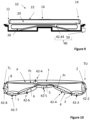
- FIG. 9 shows a passenger conveyor 10, represented in this figure as moving walkway on which passengers are transported along a horizontal central region 16 between a first landing region 12 and a second landing region 14.
- the passenger conveyor 10 comprises a continuous series of escalator steps 26 in the form of pallets 26.
- Balustrades 20 which each support a moving handrail 22 extend along each side of the passenger conveyor 10.
- a passenger conveyor monitoring system 40 includes an acceleration sensor 42 provided on one of the escalator step 26, and a controller 50.
- the acceleration sensor 42 acts as a fault detection sensor 44.
- Figure 10 shows a schematic representation of a closed loop path P of Figure 9 .
- the closed loop path P of Figure 10 eight regions are defined 1, 2, 3, 4, 5, 6, 7, 8.
- Orientation of the acceleration sensor 42 in each region 1, 2, 3, 4, 5, 6, 7, 8 is schematically represented by references 42-1, 42-2, 42-3, 42-4, 42-5, 42-6, 42-7 and 42-8.
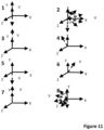
- FIG 11 shows acceleration due to gravity acting upon the acceleration sensor 42, i.e. the gravity vector V, in each region 1, 2, 3, 4, 5, 6, 7, 8 of the closed loop path P of Figure 9 .
- the acceleration sensor 42 mounted to a escalator step 26, moves in a clockwise direction around the closed loop path P, starting in region 1 and moving through regions 2, 3, 4, 5, 6, 7, 8 and then back to region 1.
- the acceleration sensor 42 moves along the closed loop path P, its orientation varies, the acceleration due to gravity acting on the acceleration sensor 42, i.e. the gravity vector V (dashed lines) varies in the x, y and z axes. Variation of the gravity vector V within each region 1, 2, 3, 4, 5, 6, 7, 8 is represented with a dotted line.
- the escalator steps 26 are following a conveyance path Pc, its upper surface is facing upwards providing support for passengers, and the acceleration sensor 42-1 has its right side upwards so it detects a negative gravitational acceleration in the y direction.
- the moving handrail 22 moves around a first turning point TU and a second turning point TL and the gravity vector V changes with the changing orientation of the acceleration sensor 42.
- the acceleration sensor 42-2, 42-8 is rotated approximately ninety degrees.
- regions 3, 5 and 7 the moving handrail 22 is moving along its return path Pr and the acceleration sensor 42-3, 42-5, 42-7 is upside down.
- the previously determined region can be used to distinguish between regions 3, 5 and 6. Regions 4 and 6 can be identified due to the inclined travel of the acceleration sensor 42-4, 42-6.
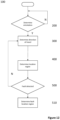
- Figure 12 shows a schematic representation of an exemplary method of monitoring a passenger conveyor 10 with the monitoring system 40.
- the acceleration sensor 42 is mounted to a moveable component 22, 26, 20 of a passenger conveyor 10 as outlined above.
- step 200 the controller 50 determines the orientation of the acceleration sensor 42.
- the initial orientation of the acceleration sensor 42 is defined in order to interpret the data collected.
- step 300 the controller 50 determines a direction of travel of the acceleration sensor 42.
- step 400 the controller 50 determines a location region of the acceleration sensor 42.
- the controller 50 monitors the location of the acceleration sensor 42 and when data is received which indicates a fault (step 500), the controller 50 determines in which region the indicated fault is located (step 510).
- the fault data could be generated by the acceleration sensor 42 or by another fault detection sensor 44 located adjacent to the acceleration sensor 42.
- the controller 50 can be configured to define the regions of the closed loop path P when an acceleration sensor 42 has been installed on a movable component 22, 26, 30 in a passenger conveyor 10. During the set-up process, the controller 50 monitors data relating to the gravity vector V and a start-up acceleration A. The controller 50 analyses the monitored data to establish patterns in order to define the different regions in the closed loop path P. Once the set-up is complete, the controller 50 monitors the current location in order to determine in which region the acceleration sensor 42 is located. The set-up process could be carried out in step 200 of the process described in Figure 12 .
- the determination of the orientation of the acceleration sensor 42 can be achieved manually when the acceleration sensor 42 is installed in the passenger conveyor 10.
- the acceleration sensor 42 could include markings to indicate the correct orientation to the maintenance engineer.
- the monitoring system 40 can follow a self-orientation determination process.
- Figure 13 is a schematic representation of an exemplary orientation determination process 200 of the method of Figure 12 .
- the process 200 of figure 13 describes how the orientation of an acceleration sensor 42 moving in the closed loop path P shown in Figure 2 can be determined.
- a self-orientation process can be defined for any closed loop path P.
- step 210 the controller 50 determines whether the acceleration sensor 42 is mounted on the escalator step 26. This could be a manual operation carried out by the maintenance engineer. Alternatively or additionally (for example as a system check), data from the acceleration sensor 42 can be used to determine whether it is mounted. After power-up, the acceleration sensor 42 is determined not to be mounted if the detected motion is not consistent with recognised passenger conveyor 10 movement, meaning that the acceleration sensor 42 is probably being manually handled, for example if there is a significant gravity vector V in the z axis for longer than 50 msec, or it is in storage.
- the acceleration sensor 42 is mounted if the detected motion is consistent with recognised passenger conveyor 10 movement, for example if the gravity vector V is stationary for more than 30 seconds, then rotates in the same direction of the XY plane through a complete 360 degrees over a time period of greater than 30 seconds.
- step 220 the controller 50 determines whether the acceleration sensor 42 is in region 4.
- the acceleration sensor 42 is located in region 4 if the gravity vector V is in the positive y direction (upside down) with an x offset of more than 15 degrees (either positive or negative).
- step 230 the controller 50 analyses the gravity vector V component in the x-axis and sets the orientation accordingly in steps 240 and 250. In step 260, this is stored in the controller 50 until the acceleration sensor 42 is next powered up.
- the determination of the direction of travel of the acceleration sensor 42 is achieved by the controller 50 monitoring both the gravity vector V and a start-up acceleration A of the acceleration sensor 42. This can be determined for any closed loop path P.
- Figure 14a shows the variation of acceleration due to gravity acting upon the acceleration sensor 42, i.e. the gravity vector V (dashed line) as the passenger conveyor 10 of Figures 1 and 2 moves upwards, and the acceleration sensor 42 moves in an clockwise direction around the closed loop path P.
- the start-up acceleration A in each region 1, 2, 3, 4, 5, 6 is represented with an arrow depicted on the gravity vector V.
- Figure 14b shows the variation of the gravity vector V and the start-up acceleration A as the passenger conveyor 10 of Figures 1 and 2 moves downwards, and the acceleration sensor 42 moves in an anti-clockwise direction around the closed loop path P.
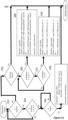
- Figure 15 is a schematic representation of an exemplary process 300 for determining the direction of travel of the acceleration sensor 42 in the method of Figure 12 .
- the process 300 of Figure 15 describes how the direction of travel of the acceleration sensor 42 moving in the closed loop path P shown in Figure 2 can be determined. However, it will be appreciated that a process can be defined for any closed loop path P.
- step 310 the controller 50 determines whether the passenger conveyor 10 is in motion. This can be done by detecting recognised passenger conveyor 10 movement, for example it can be determined that the acceleration sensor 42 is in motion if there are vibrations greater than 5 milli-Gs in at least 2 axes.
- the controller 50 determines whether the acceleration sensor 42 is in regions 1, 3, or 5 (step 320). This determination is made by comparing the current gravity vector V to the known gravity vectors for each region.
- the acceleration sensor 42 is located in region 1 if the gravity vector V is in the negative Y direction (right-side up) with an X offset of less than 2 degrees (either positive or negative).
- the acceleration sensor 42 is located in either region 3 or region 5 if the gravity vector V is in the positive Y direction (upside down) with an X offset of less than 2 degrees (either positive or negative).
- step 320 if the acceleration sensor is not in region 1, 3 or 5, the controller continues to monitor for motion (step 310).
- the controller 50 continues to monitor for motion (step 330) and once the acceleration sensor 42 starts to move, a determination of direction of travel can be made based on the orientation of the acceleration sensor 42 and whether the change in start-up acceleration A in the x direction is positive or negative (step 340).
- step 310 if the acceleration sensor 42 is in motion the controller 50 checks whether the direction is already known (step 350). If not, the controller 50 determines whether the acceleration sensor 42 is in regions 1, 3, or 5 (step 360) as outlined above. If the acceleration sensor 42 is in region 1, 3 or 5, the controller 50 determines a direction of travel based on the orientation of the acceleration sensor 42, the current direction of the gravity vector V and the previous direction of the gravity vector V (step 380).
- the controller 50 determines whether the acceleration sensor 42 is in region 2 or 6 (step 370).
- the mid-point of regions 2 and 6 can be identified as the gravity vector is in the positive or negative X direction. If yes, the controller 50 determines a direction of travel based on the orientation of the acceleration sensor 42 and whether the start-up acceleration A in the x direction is positive or negative (step 390).
- the controller 50 checks again whether the acceleration sensor 42 is in regions 1, 3 or 5 (step 360).
- the determination of a current location region of the acceleration sensor 42 is achieved by the controller 50 monitoring the gravity vector V taking into account the direction of travel. This can be determined for any closed loop path P.
- the controller 50 monitors the location of the acceleration sensor 42 and when data is received which indicates a fault, the controller 50 can determine in which region the indicated fault is located.
- the fault data could be generated by the acceleration sensor 42 or by another fault detection sensor located adjacent to the acceleration sensor 42.
- Figure 16 is a schematic representation of an exemplary process 400 for determining the location of the acceleration sensor 42 in the method of Figure 12 .
- the process 300 of Figure 15 describes how the direction of travel of the acceleration sensor 42 moving in the closed loop path P shown in Figure 2 can be determined. However, it will be appreciated that a process can be defined for any closed loop path P.
- step 410 the controller 50 determines whether the gravity vector V is entirely in the y-axis, and if yes in step 440 the controller 50 checks the direction of the gravity vector V. When the gravity vector V is negative in the y-axis, the controller 50 determines that the acceleration sensor 42 is in region 1 (step 445).
- step 450 the controller 50 checks the determined direction of travel (step 450). If the direction is up, the controller 50 checks the previous location region to determine whether the current location region is 2 or 4 (step 455). If the direction is down, the controller 50 checks the previous location region to determine whether the current location region is 4 or 6 (step 460).
- step 410 determines whether the gravity vector V is entirely in the x-axis (step 420). If yes, in step 470 the controller 50 checks the direction of the gravity vector V. If the gravity vector is negative in the x-axis, the controller 50 checks the orientation to determine whether the current location is in region 2 or 6 (step 475). If the gravity vector V is positive in the x-axis, the controller 50 checks the orientation to determine whether the current location is in region 2 or 6 (step 480). If the orientation of the acceleration sensor 42 is known, then it is be possible to determine whether the current location is 2 or 6 based on the direction of the gravity vector V, i.e. in region 2 it will be in the positive x direction.
- step 420 determines if the gravity vector V is mostly in the positive y axis but also in the x direction (step 430). If yes, the controller 50 determines that the location is in region 4 (step 490). If no, then the controller 50 repeats step 410.
- monitoring system 40 and monitoring method 400 described can be used on any component in a passenger conveyor 10 which moves in a defined closed loop path P.
Landscapes
- Escalators And Moving Walkways (AREA)
Claims (13)
- Überwachungssystem (40) für einen Personenförderer (10), umfassend mindestens einen Beschleunigungssensor (42), der an einer beweglichen Komponente (22, 26, 30) des Personenförderers (10) bereitgestellt ist, wobei sich die bewegliche Komponente (22, 26, 30) in einem geschlossenen Kreislaufweg (P) bewegt, wenn der Personenförderer (10) in Gebrauch ist;einen Fehlererkennungssensor (44), der dem oder jedem Beschleunigungssensor (42) zugeordnet und dazu konfiguriert ist, Daten bereitzustellen, die einen Fehler in der beweglichen Komponente (22, 26, 30) angeben; undeine Steuerung (50), die zu Folgendem konfiguriert ist:Empfangen von Daten von dem oder jedem Beschleunigungssensor (42) ;Überwachen eines Schwerkraftvektors (V) des oder jedes Beschleunigungssensors (42);Bestimmen einer Fahrtrichtung des oder jedes Beschleunigungssensors (42);Bestimmen einer aktuellen Position des oder jedes Beschleunigungssensors (42) basierend auf dem überwachten Schwerkraftvektor (V) und der bestimmten Fahrtrichtung;Erkennen eines Fehlers aus den von dem oder jedem Fehlererkennungssensor (44) empfangenen Daten;Ermitteln einer Position des erkannten Fehlers basierend auf der bestimmten aktuellen Position des zugeordneten Beschleunigungssensors (42);dadurch gekennzeichnet, dass die Steuerung (50) ferner zu Folgendem konfiguriert ist:Überwachen einer Anfahrbeschleunigung (A) des oder jedes Beschleunigungssensors (42)und Bestimmen der Fahrtrichtung des oder jedes Beschleunigungssensors (42) basierend auf der überwachten Anfahrbeschleunigung (A) und dem überwachten Schwerkraftvektor (V) .
- Überwachungssystem (40) nach Anspruch 1, wobei die Steuerung (50) dazu konfiguriert ist, die aktuelle Position des Beschleunigungssensors (42) in Bezug auf eine Vielzahl von vordefinierten Bereichen des geschlossenen Kreislaufwegs (P) zu bestimmen.
- Überwachungssystem (40) nach Anspruch 1, wobei mindestens ein Beschleunigungssensor (42) als zugeordneter Fehlererkennungssensor (44) fungiert.
- Überwachungssystem (40) nach einem der vorhergehenden Ansprüche, wobei mindestens ein Fehlererkennungssensor (44) benachbart zu dem zugeordneten Beschleunigungssensor (42) bereitgestellt ist.
- Überwachungssystem (40) nach einem der vorhergehenden Ansprüche, wobei die Steuerung (50) ferner dazu konfiguriert ist, eine Ausrichtung des oder jedes Beschleunigungssensors (42) nach dem Einschalten des Beschleunigungssensors (42) zu bestimmen.
- Überwachungssystem (40) nach einem der vorhergehenden Ansprüche, ferner umfassend einen Steuerstand (52), der sich entfernt von dem Personenförderer (10) befindet.
- Personenförderer (10), umfassend ein Überwachungssystem (40) nach einem der vorhergehenden Ansprüche.
- Personenförderer (10) nach Anspruch 7, wobei der Personenförderer (10) eine Rolltreppe und die bewegliche Komponente eine Rolltreppenstufe (26) ist.
- Verfahren (100) zum Überwachen eines Personenförderers (10), umfassend:Empfangen von Daten von einem Beschleunigungssensor (42), der an einer beweglichen Komponente (22, 26, 30) des Personenförderers (10) bereitgestellt ist;Überwachen eines Schwerkraftvektors (V) des Beschleunigungssensors (42);Bestimmen einer Fahrtrichtung des Beschleunigungssensors (42);Bestimmen einer aktuellen Position des Beschleunigungssensors (42) basierend auf dem überwachten Schwerkraftvektor (V) und der bestimmten Fahrtrichtung;Empfangen von Daten, die einen Fehler in der beweglichen Komponente (22, 26, 30) angeben;Erkennen eines Fehlers aus den von dem Fehlererkennungssensor (44) empfangenen Daten;Ermitteln einer Position des erkannten Fehlers basierend auf der bestimmten aktuellen Position des Beschleunigungssensors (42);dadurch gekennzeichnet, dass der Schritt des Bestimmens einer Fahrtrichtung des Beschleunigungssensors (42) Folgendes beinhaltet:Überwachen einer Anfahrbeschleunigung (A) des Beschleunigungssensors (42); undBestimmen der Fahrtrichtung basierend auf der bestimmten überwachten Anfahrbeschleunigung (A) und dem überwachten Schwerkraftvektor (V).
- Verfahren (100) nach Anspruch 9, wobei der Schritt des Ermittelns einer Position des erkannten Fehlers Bestimmen der aktuellen Position in Bezug auf eine Vielzahl von vordefinierten Bereichen des geschlossenen Kreislaufwegs (P) beinhaltet.
- Verfahren (100) nach einem der Ansprüche 8 oder 9, wobei der Schritt des Empfangens von Daten, die einen Fehler in der beweglichen Komponente (22, 26, 30) angeben, Empfangen von Daten von dem Beschleunigungssensor (42) beinhaltet.
- Verfahren (100) nach einem der Ansprüche 8 bis 11, ferner umfassend:
Bestimmen einer Ausrichtung des Beschleunigungssensors (42) nach dem Einschalten des Beschleunigungssensors (42). - Verfahren (100) nach einem der Ansprüche 8 bis 12, ferner umfassend:
Übermitteln von Daten an einen Steuerstand (52), der sich entfernt von dem Personenförderer (10) befindet.
Priority Applications (3)
| Application Number | Priority Date | Filing Date | Title |
|---|---|---|---|
| EP20161811.3A EP3878793B1 (de) | 2020-03-09 | 2020-03-09 | Überwachungssysteme für personenförderer |
| US16/953,223 US11214466B2 (en) | 2020-03-09 | 2020-11-19 | Monitoring systems for passenger conveyors |
| CN202011399609.2A CN113371578A (zh) | 2020-03-09 | 2020-12-04 | 用于乘客输送机的监控系统 |
Applications Claiming Priority (1)
| Application Number | Priority Date | Filing Date | Title |
|---|---|---|---|
| EP20161811.3A EP3878793B1 (de) | 2020-03-09 | 2020-03-09 | Überwachungssysteme für personenförderer |
Publications (2)
| Publication Number | Publication Date |
|---|---|
| EP3878793A1 EP3878793A1 (de) | 2021-09-15 |
| EP3878793B1 true EP3878793B1 (de) | 2025-06-11 |
Family
ID=69784174
Family Applications (1)
| Application Number | Title | Priority Date | Filing Date |
|---|---|---|---|
| EP20161811.3A Active EP3878793B1 (de) | 2020-03-09 | 2020-03-09 | Überwachungssysteme für personenförderer |
Country Status (3)
| Country | Link |
|---|---|
| US (1) | US11214466B2 (de) |
| EP (1) | EP3878793B1 (de) |
| CN (1) | CN113371578A (de) |
Families Citing this family (2)
| Publication number | Priority date | Publication date | Assignee | Title |
|---|---|---|---|---|
| JP7803812B2 (ja) * | 2022-08-12 | 2026-01-21 | 株式会社日立製作所 | 乗客コンベア検査システム及び乗客コンベア検査方法 |
| CN221680510U (zh) * | 2023-12-12 | 2024-09-10 | 奥的斯电梯公司 | 乘客输送机的梯级以及乘客输送机 |
Citations (1)
| Publication number | Priority date | Publication date | Assignee | Title |
|---|---|---|---|---|
| EP1634843A2 (de) * | 2004-09-10 | 2006-03-15 | Hitachi, Ltd. | Inspektionstreppe für Rolltreppe |
Family Cites Families (15)
| Publication number | Priority date | Publication date | Assignee | Title |
|---|---|---|---|---|
| JP2523927B2 (ja) * | 1990-04-11 | 1996-08-14 | 株式会社日立製作所 | 乗客コンベアの制御装置 |
| JP3249024B2 (ja) * | 1995-03-02 | 2002-01-21 | 株式会社日立ビルシステム | エレベーターの走行特性検査装置 |
| JP4020204B2 (ja) * | 2003-08-26 | 2007-12-12 | 三菱電機株式会社 | マンコンベア点検装置 |
| JP4791093B2 (ja) * | 2005-07-04 | 2011-10-12 | 三菱電機株式会社 | 乗客コンベアの診断装置 |
| BRPI0924913A2 (pt) * | 2009-04-20 | 2015-07-07 | Otis Elevator Co | Aparelho e método para detectar um degrau perdido ou desalinhado de um transportador |
| JP4829335B2 (ja) * | 2009-11-04 | 2011-12-07 | 株式会社東芝 | 搬送コンベアの診断装置及びその診断システム |
| JP2011105434A (ja) * | 2009-11-16 | 2011-06-02 | Toshiba Elevator Co Ltd | エスカレータ管理装置 |
| EP2468676A1 (de) * | 2010-12-22 | 2012-06-27 | Inventio AG | Fördereinrichtung für Personen und/oder Gegenstände |
| JP5825989B2 (ja) * | 2011-11-17 | 2015-12-02 | 東芝エレベータ株式会社 | マンコンベア点検装置 |
| CN203199865U (zh) * | 2012-11-15 | 2013-09-18 | 东芝电梯株式会社 | 乘客输送机检查装置 |
| CN107665326B (zh) * | 2016-07-29 | 2024-02-09 | 奥的斯电梯公司 | 乘客运输装置的监测系统、乘客运输装置及其监测方法 |
| US10669121B2 (en) * | 2017-06-30 | 2020-06-02 | Otis Elevator Company | Elevator accelerometer sensor data usage |
| CN109764856B (zh) * | 2019-02-28 | 2020-12-15 | 中国民航大学 | 基于mems传感器的道面坡度提取方法 |
| CN110346601A (zh) * | 2019-08-08 | 2019-10-18 | 崔淼 | 预制道床姿态监测系统及监测方法 |
| EP3819252B1 (de) * | 2019-11-08 | 2023-06-07 | OTIS Elevator Company | Überwachungssysteme für geneigte personenförderer |
-
2020
- 2020-03-09 EP EP20161811.3A patent/EP3878793B1/de active Active
- 2020-11-19 US US16/953,223 patent/US11214466B2/en not_active Expired - Fee Related
- 2020-12-04 CN CN202011399609.2A patent/CN113371578A/zh active Pending
Patent Citations (1)
| Publication number | Priority date | Publication date | Assignee | Title |
|---|---|---|---|---|
| EP1634843A2 (de) * | 2004-09-10 | 2006-03-15 | Hitachi, Ltd. | Inspektionstreppe für Rolltreppe |
Also Published As
| Publication number | Publication date |
|---|---|
| US11214466B2 (en) | 2022-01-04 |
| CN113371578A (zh) | 2021-09-10 |
| US20210276833A1 (en) | 2021-09-09 |
| EP3878793A1 (de) | 2021-09-15 |
Similar Documents
| Publication | Publication Date | Title |
|---|---|---|
| CN112777467B (zh) | 用于倾斜乘客输送机的监测系统 | |
| CN1099371C (zh) | 乘客输送设备的数据采集和分析系统 | |
| EP3882204B1 (de) | Aufzugsinspektionssystem mit robotischer plattform, konfiguriert zur entwicklung von schachtmodelldaten von sensordaten | |
| EP3640178B1 (de) | Bestimmung der position einer aufzugskabine mittels vibration | |
| US10961082B2 (en) | Elevator inspection using automated sequencing of camera presets | |
| EP3878793B1 (de) | Überwachungssysteme für personenförderer | |
| CN113844965B (zh) | 视觉检视诊断 | |
| EP3882206A1 (de) | Aufzugsinspektionssystem mit roboterplattform mit konfiguration zur inspektion von betriebs- und ausrichtungsbedingungen von komponenten in einem aufzugsschacht | |
| EP3882203B1 (de) | Aufzugsinspektionssystem mit robotischer plattform, konfiguriert zur entwicklung von schachtmodelldaten von über ein netzwerk verbundenen aufzugssystemen | |
| EP3882202B1 (de) | Aufzugsinspektionssystem mit einer roboterplattform mit einem plattformantrieb | |
| CN113371569A (zh) | 电梯安全系统 | |
| EP3381853B1 (de) | Aufzugsnachlaufprüfsysteme und -verfahren | |
| US10850948B2 (en) | Escalator with a sensor for detecting sheave misalignment | |
| EP3643669B1 (de) | Gesundheitsüberwachung für aufzugs- und rolltreppensysteme | |
| EP3882205B1 (de) | Aufzugsinspektionssystem mit roboter zur inspektion der betriebsbedingungen einer aufzugskabine | |
| CN114502494B (zh) | 电梯装置以及异常检测方法 | |
| KR100202710B1 (ko) | 엘리베이터의 구출 운전 장치 및 방법 | |
| CN118047292A (zh) | 乘客输送机诊断装置以及梯级诊断方法 | |
| CN120191809A (zh) | 用于预测对至少一个部件的维护需要的系统和方法 |
Legal Events
| Date | Code | Title | Description |
|---|---|---|---|
| PUAI | Public reference made under article 153(3) epc to a published international application that has entered the european phase |
Free format text: ORIGINAL CODE: 0009012 |
|
| STAA | Information on the status of an ep patent application or granted ep patent |
Free format text: STATUS: THE APPLICATION HAS BEEN PUBLISHED |
|
| AK | Designated contracting states |
Kind code of ref document: A1 Designated state(s): AL AT BE BG CH CY CZ DE DK EE ES FI FR GB GR HR HU IE IS IT LI LT LU LV MC MK MT NL NO PL PT RO RS SE SI SK SM TR |
|
| STAA | Information on the status of an ep patent application or granted ep patent |
Free format text: STATUS: REQUEST FOR EXAMINATION WAS MADE |
|
| 17P | Request for examination filed |
Effective date: 20220315 |
|
| RBV | Designated contracting states (corrected) |
Designated state(s): AL AT BE BG CH CY CZ DE DK EE ES FI FR GB GR HR HU IE IS IT LI LT LU LV MC MK MT NL NO PL PT RO RS SE SI SK SM TR |
|
| GRAP | Despatch of communication of intention to grant a patent |
Free format text: ORIGINAL CODE: EPIDOSNIGR1 |
|
| STAA | Information on the status of an ep patent application or granted ep patent |
Free format text: STATUS: GRANT OF PATENT IS INTENDED |
|
| INTG | Intention to grant announced |
Effective date: 20250123 |
|
| RIN1 | Information on inventor provided before grant (corrected) |
Inventor name: TRCKA, NIKOLA Inventor name: WITCZAK, TADEUSZ PAWEL Inventor name: SCHEDL, PHILIPP Inventor name: BOGLI, CRAIG DREW Inventor name: TAKACS, ROBERT |
|
| GRAS | Grant fee paid |
Free format text: ORIGINAL CODE: EPIDOSNIGR3 |
|
| GRAA | (expected) grant |
Free format text: ORIGINAL CODE: 0009210 |
|
| STAA | Information on the status of an ep patent application or granted ep patent |
Free format text: STATUS: THE PATENT HAS BEEN GRANTED |
|
| AK | Designated contracting states |
Kind code of ref document: B1 Designated state(s): AL AT BE BG CH CY CZ DE DK EE ES FI FR GB GR HR HU IE IS IT LI LT LU LV MC MK MT NL NO PL PT RO RS SE SI SK SM TR |
|
| REG | Reference to a national code |
Ref country code: GB Ref legal event code: FG4D |
|
| REG | Reference to a national code |
Ref country code: CH Ref legal event code: EP |
|
| REG | Reference to a national code |
Ref country code: IE Ref legal event code: FG4D |
|
| REG | Reference to a national code |
Ref country code: DE Ref legal event code: R096 Ref document number: 602020052527 Country of ref document: DE |
|
| PG25 | Lapsed in a contracting state [announced via postgrant information from national office to epo] |
Ref country code: ES Free format text: LAPSE BECAUSE OF FAILURE TO SUBMIT A TRANSLATION OF THE DESCRIPTION OR TO PAY THE FEE WITHIN THE PRESCRIBED TIME-LIMIT Effective date: 20250611 Ref country code: FI Free format text: LAPSE BECAUSE OF FAILURE TO SUBMIT A TRANSLATION OF THE DESCRIPTION OR TO PAY THE FEE WITHIN THE PRESCRIBED TIME-LIMIT Effective date: 20250611 |
|
| REG | Reference to a national code |
Ref country code: LT Ref legal event code: MG9D |
|
| PG25 | Lapsed in a contracting state [announced via postgrant information from national office to epo] |
Ref country code: NO Free format text: LAPSE BECAUSE OF FAILURE TO SUBMIT A TRANSLATION OF THE DESCRIPTION OR TO PAY THE FEE WITHIN THE PRESCRIBED TIME-LIMIT Effective date: 20250911 Ref country code: GR Free format text: LAPSE BECAUSE OF FAILURE TO SUBMIT A TRANSLATION OF THE DESCRIPTION OR TO PAY THE FEE WITHIN THE PRESCRIBED TIME-LIMIT Effective date: 20250912 |
|
| REG | Reference to a national code |
Ref country code: NL Ref legal event code: MP Effective date: 20250611 |
|
| PG25 | Lapsed in a contracting state [announced via postgrant information from national office to epo] |
Ref country code: BG Free format text: LAPSE BECAUSE OF FAILURE TO SUBMIT A TRANSLATION OF THE DESCRIPTION OR TO PAY THE FEE WITHIN THE PRESCRIBED TIME-LIMIT Effective date: 20250611 |
|
| PG25 | Lapsed in a contracting state [announced via postgrant information from national office to epo] |
Ref country code: HR Free format text: LAPSE BECAUSE OF FAILURE TO SUBMIT A TRANSLATION OF THE DESCRIPTION OR TO PAY THE FEE WITHIN THE PRESCRIBED TIME-LIMIT Effective date: 20250611 |
|
| PG25 | Lapsed in a contracting state [announced via postgrant information from national office to epo] |
Ref country code: RS Free format text: LAPSE BECAUSE OF FAILURE TO SUBMIT A TRANSLATION OF THE DESCRIPTION OR TO PAY THE FEE WITHIN THE PRESCRIBED TIME-LIMIT Effective date: 20250911 |
|
| PG25 | Lapsed in a contracting state [announced via postgrant information from national office to epo] |
Ref country code: LV Free format text: LAPSE BECAUSE OF FAILURE TO SUBMIT A TRANSLATION OF THE DESCRIPTION OR TO PAY THE FEE WITHIN THE PRESCRIBED TIME-LIMIT Effective date: 20250611 |
|
| PG25 | Lapsed in a contracting state [announced via postgrant information from national office to epo] |
Ref country code: NL Free format text: LAPSE BECAUSE OF FAILURE TO SUBMIT A TRANSLATION OF THE DESCRIPTION OR TO PAY THE FEE WITHIN THE PRESCRIBED TIME-LIMIT Effective date: 20250611 |
|
| PG25 | Lapsed in a contracting state [announced via postgrant information from national office to epo] |
Ref country code: PT Free format text: LAPSE BECAUSE OF FAILURE TO SUBMIT A TRANSLATION OF THE DESCRIPTION OR TO PAY THE FEE WITHIN THE PRESCRIBED TIME-LIMIT Effective date: 20251013 |
|
| REG | Reference to a national code |
Ref country code: AT Ref legal event code: MK05 Ref document number: 1802209 Country of ref document: AT Kind code of ref document: T Effective date: 20250611 |
|
| PG25 | Lapsed in a contracting state [announced via postgrant information from national office to epo] |
Ref country code: IS Free format text: LAPSE BECAUSE OF FAILURE TO SUBMIT A TRANSLATION OF THE DESCRIPTION OR TO PAY THE FEE WITHIN THE PRESCRIBED TIME-LIMIT Effective date: 20251011 |
|
| PG25 | Lapsed in a contracting state [announced via postgrant information from national office to epo] |
Ref country code: AT Free format text: LAPSE BECAUSE OF FAILURE TO SUBMIT A TRANSLATION OF THE DESCRIPTION OR TO PAY THE FEE WITHIN THE PRESCRIBED TIME-LIMIT Effective date: 20250611 Ref country code: SM Free format text: LAPSE BECAUSE OF FAILURE TO SUBMIT A TRANSLATION OF THE DESCRIPTION OR TO PAY THE FEE WITHIN THE PRESCRIBED TIME-LIMIT Effective date: 20250611 |
|
| PG25 | Lapsed in a contracting state [announced via postgrant information from national office to epo] |
Ref country code: CZ Free format text: LAPSE BECAUSE OF FAILURE TO SUBMIT A TRANSLATION OF THE DESCRIPTION OR TO PAY THE FEE WITHIN THE PRESCRIBED TIME-LIMIT Effective date: 20250611 |
|
| PG25 | Lapsed in a contracting state [announced via postgrant information from national office to epo] |
Ref country code: PL Free format text: LAPSE BECAUSE OF FAILURE TO SUBMIT A TRANSLATION OF THE DESCRIPTION OR TO PAY THE FEE WITHIN THE PRESCRIBED TIME-LIMIT Effective date: 20250611 |
|
| PG25 | Lapsed in a contracting state [announced via postgrant information from national office to epo] |
Ref country code: EE Free format text: LAPSE BECAUSE OF FAILURE TO SUBMIT A TRANSLATION OF THE DESCRIPTION OR TO PAY THE FEE WITHIN THE PRESCRIBED TIME-LIMIT Effective date: 20250611 |
|
| PG25 | Lapsed in a contracting state [announced via postgrant information from national office to epo] |
Ref country code: SK Free format text: LAPSE BECAUSE OF FAILURE TO SUBMIT A TRANSLATION OF THE DESCRIPTION OR TO PAY THE FEE WITHIN THE PRESCRIBED TIME-LIMIT Effective date: 20250611 Ref country code: RO Free format text: LAPSE BECAUSE OF FAILURE TO SUBMIT A TRANSLATION OF THE DESCRIPTION OR TO PAY THE FEE WITHIN THE PRESCRIBED TIME-LIMIT Effective date: 20250611 |
|
| REG | Reference to a national code |
Ref country code: DE Ref legal event code: R097 Ref document number: 602020052527 Country of ref document: DE |
|
| PG25 | Lapsed in a contracting state [announced via postgrant information from national office to epo] |
Ref country code: DK Free format text: LAPSE BECAUSE OF FAILURE TO SUBMIT A TRANSLATION OF THE DESCRIPTION OR TO PAY THE FEE WITHIN THE PRESCRIBED TIME-LIMIT Effective date: 20250611 |
|
| PG25 | Lapsed in a contracting state [announced via postgrant information from national office to epo] |
Ref country code: IT Free format text: LAPSE BECAUSE OF FAILURE TO SUBMIT A TRANSLATION OF THE DESCRIPTION OR TO PAY THE FEE WITHIN THE PRESCRIBED TIME-LIMIT Effective date: 20250611 |
|
| PLBE | No opposition filed within time limit |
Free format text: ORIGINAL CODE: 0009261 |
|
| STAA | Information on the status of an ep patent application or granted ep patent |
Free format text: STATUS: NO OPPOSITION FILED WITHIN TIME LIMIT |
|
| REG | Reference to a national code |
Ref country code: CH Ref legal event code: L10 Free format text: ST27 STATUS EVENT CODE: U-0-0-L10-L00 (AS PROVIDED BY THE NATIONAL OFFICE) Effective date: 20260423 |