EP3879005B1 - Appareil de compression électrochimique d'hydrogène et méthode pour opérer un appareil de compression électrochimique d'hydrogène - Google Patents
Appareil de compression électrochimique d'hydrogène et méthode pour opérer un appareil de compression électrochimique d'hydrogène Download PDFInfo
- Publication number
- EP3879005B1 EP3879005B1 EP19882291.8A EP19882291A EP3879005B1 EP 3879005 B1 EP3879005 B1 EP 3879005B1 EP 19882291 A EP19882291 A EP 19882291A EP 3879005 B1 EP3879005 B1 EP 3879005B1
- Authority
- EP
- European Patent Office
- Prior art keywords
- hydrogen
- anode
- containing gas
- cell
- dew point
- Prior art date
- Legal status (The legal status is an assumption and is not a legal conclusion. Google has not performed a legal analysis and makes no representation as to the accuracy of the status listed.)
- Active
Links
Images

Classifications
-
- C—CHEMISTRY; METALLURGY
- C01—INORGANIC CHEMISTRY
- C01B—NON-METALLIC ELEMENTS; COMPOUNDS THEREOF; METALLOIDS OR COMPOUNDS THEREOF NOT COVERED BY SUBCLASS C01C
- C01B3/00—Hydrogen; Gaseous mixtures containing hydrogen; Separation of hydrogen from mixtures containing it; Purification of hydrogen; Reversible storage of hydrogen
-
- C—CHEMISTRY; METALLURGY
- C25—ELECTROLYTIC OR ELECTROPHORETIC PROCESSES; APPARATUS THEREFOR
- C25B—ELECTROLYTIC OR ELECTROPHORETIC PROCESSES FOR THE PRODUCTION OF COMPOUNDS OR NON-METALS; APPARATUS THEREFOR
- C25B1/00—Electrolytic production of inorganic compounds or non-metals
- C25B1/01—Products
- C25B1/02—Hydrogen or oxygen
-
- C—CHEMISTRY; METALLURGY
- C25—ELECTROLYTIC OR ELECTROPHORETIC PROCESSES; APPARATUS THEREFOR
- C25B—ELECTROLYTIC OR ELECTROPHORETIC PROCESSES FOR THE PRODUCTION OF COMPOUNDS OR NON-METALS; APPARATUS THEREFOR
- C25B15/00—Operating or servicing cells
- C25B15/02—Process control or regulation
-
- C—CHEMISTRY; METALLURGY
- C25—ELECTROLYTIC OR ELECTROPHORETIC PROCESSES; APPARATUS THEREFOR
- C25B—ELECTROLYTIC OR ELECTROPHORETIC PROCESSES FOR THE PRODUCTION OF COMPOUNDS OR NON-METALS; APPARATUS THEREFOR
- C25B15/00—Operating or servicing cells
- C25B15/02—Process control or regulation
- C25B15/023—Measuring, analysing or testing during electrolytic production
- C25B15/025—Measuring, analysing or testing during electrolytic production of electrolyte parameters
- C25B15/027—Temperature
-
- C—CHEMISTRY; METALLURGY
- C25—ELECTROLYTIC OR ELECTROPHORETIC PROCESSES; APPARATUS THEREFOR
- C25B—ELECTROLYTIC OR ELECTROPHORETIC PROCESSES FOR THE PRODUCTION OF COMPOUNDS OR NON-METALS; APPARATUS THEREFOR
- C25B15/00—Operating or servicing cells
- C25B15/08—Supplying or removing reactants or electrolytes; Regeneration of electrolytes
-
- C—CHEMISTRY; METALLURGY
- C25—ELECTROLYTIC OR ELECTROPHORETIC PROCESSES; APPARATUS THEREFOR
- C25B—ELECTROLYTIC OR ELECTROPHORETIC PROCESSES FOR THE PRODUCTION OF COMPOUNDS OR NON-METALS; APPARATUS THEREFOR
- C25B9/00—Cells or assemblies of cells; Constructional parts of cells; Assemblies of constructional parts, e.g. electrode-diaphragm assemblies; Process-related cell features
- C25B9/17—Cells comprising dimensionally-stable non-movable electrodes; Assemblies of constructional parts thereof
- C25B9/19—Cells comprising dimensionally-stable non-movable electrodes; Assemblies of constructional parts thereof with diaphragms
- C25B9/23—Cells comprising dimensionally-stable non-movable electrodes; Assemblies of constructional parts thereof with diaphragms comprising ion-exchange membranes in or on which electrode material is embedded
-
- Y—GENERAL TAGGING OF NEW TECHNOLOGICAL DEVELOPMENTS; GENERAL TAGGING OF CROSS-SECTIONAL TECHNOLOGIES SPANNING OVER SEVERAL SECTIONS OF THE IPC; TECHNICAL SUBJECTS COVERED BY FORMER USPC CROSS-REFERENCE ART COLLECTIONS [XRACs] AND DIGESTS
- Y02—TECHNOLOGIES OR APPLICATIONS FOR MITIGATION OR ADAPTATION AGAINST CLIMATE CHANGE
- Y02E—REDUCTION OF GREENHOUSE GAS [GHG] EMISSIONS, RELATED TO ENERGY GENERATION, TRANSMISSION OR DISTRIBUTION
- Y02E60/00—Enabling technologies; Technologies with a potential or indirect contribution to GHG emissions mitigation
- Y02E60/30—Hydrogen technology
- Y02E60/50—Fuel cells
Definitions
- the present disclosure relates to an electrochemical hydrogen compressor and to a method for operating the electrochemical hydrogen compressor.
- PTL 1 discloses a hydrogen purification/pressure boosting system in which a voltage is applied between an anode and a cathode that hold an electrolyte membrane therebetween to thereby purify hydrogen and boost the pressure of the hydrogen. Specifically, when a current flows between the anode and the cathode, hydrogen in the anode is converted to protons, and the protons together with entrained water molecules migrate from the anode to the cathode through the electrolyte membrane and are reconverted to hydrogen in the cathode.
- a stacked structure including the anode, the electrolyte membrane, and the cathode is hereinafter referred to as a membrane electrode assembly (MEA).
- MEA membrane electrode assembly
- the use of a technology called P2G (Power to Gas) in which hydrogen generated by water electrolysis using surplus power from renewable energy is stored in a hydrogen reservoir allows the system built to address, for example, the time lag between the power obtained from the renewable energy and power demand.
- the hydrogen purification/pressure boosting system disclosed in PTL 1 may be used to store hydrogen obtained in the water electrolysis device at high presser (e.g., about 20 MPa) in the hydrogen reservoir.
- an electrochemical hydrogen compressor may be used to store hydrogen obtained, for example, by reforming town gas in a hydrogen reservoir at high pressure (e.g., about 40 MPa).
- the hydrogen reservoir can be used as a hydrogen source for a forklift equipped with a fuel cell.
- EP 3 556 906 A1 , EP 3 599 656 A1 , JP 2017 145187 A and EP 3 581 681 A2 relate to electrochemical hydrogen pump.
- EP 3 492 630 A1 , JP 2018 165385 A , JP 2017 530921 A and EP 3 574 978 A1 relate to hydrogen supply system.
- One aspect of the present disclosure has been made in view of the above circumstances and provides an electrochemical hydrogen compressor that can perform the hydrogen compression operation with improved efficiency as compared to the conventional example and a method for operating the electrochemical hydrogen compressor.
- An electrochemical hydrogen compressor in one aspect of the present invention is defined in claim 1.
- An electrochemical hydrogen compressor operating method in another aspect of the present invention is defined in claim 11.
- the electrochemical hydrogen compressor and the electrochemical hydrogen compressor operating method in the above aspects of the present disclosure have the effect of improving the efficiency of the hydrogen compression operation as compared to the conventional example.
- an electrochemical hydrogen compressor using a solid polymer electrolyte membrane (hereinafter referred to as an electrolyte membrane)
- hydrogen (H 2 ) in the anode is converted to protons, and the protons are moved to the cathode.
- the protons (H + ) are reconverted to hydrogen (H 2 ) in the cathode, and the pressure of the hydrogen is thereby increased.
- the proton conductivity of the electrolyte membrane increases under high-temperature/high-humidity conditions (e.g., at about 60°C), and the efficiency of the hydrogen compression operation of the electrochemical hydrogen compressor thereby increases.
- Such an electrochemical hydrogen compressor requires a design that can withstand the pressure of high-pressure gas. Therefore, the MEA is often covered with, for example, a thick highly rigid metal member.
- a hydrogen source of the electrochemical hydrogen compressor for example, a high-humidity hydrogen-containing gas generated by water electrolysis, a high-humidity hydrogen-containing gas generated by a reforming reaction of a hydrocarbon compound, etc. is used as an anode gas of the electrochemical hydrogen compressor.
- a high-humidity hydrogen-containing gas having a dew point of about 80°C is supplied to the anode of the MEA.
- the dew point of the hydrogen-containing gas is excessively higher than the temperature of the MEA, condensation of water may occur in the MEA, and the water may soak a catalyst in the MEA. Then the condensed water may cause flooding in the anode of the MEA.
- the dew point of the hydrogen-containing gas is excessively lower than the temperature of the MEA, it may be difficult to maintain the electrolyte membrane in a wet state necessary for the electrolyte membrane to have high proton conductivity.
- a hydrogen-containing gas having a dew point approximately equal to the temperature of the MEA (full humidification) or slightly higher than the temperature of the MEA is supplied to the anode of the MEA.
- the hydrogen compression operation of the electrochemical hydrogen compressor proceeds, at least part of the hydrogen (protons) in the hydrogen-containing gas present in the anode of the MEA moves to the cathode together with entrained water, and part of water vapor in the hydrogen-containing gas condenses.
- the amount of saturated vapor that can be present in the cathode is constant, so that surplus water vapor exceeding the amount of saturated water vapor condenses. Specifically, it may be considered that about 70% of the amount of water vapor in the hydrogen-containing gas supplied to the anode is condensed in the MEA.
- a heat balance simulation from the temperature at the startup of the electrochemical hydrogen compressor (for example, 25°C) to a prescribed temperature (for example, 65°C) is unsteady analysis. Therefore, it is often difficult to perform a numerical analysis simulation using a computational model that accurately reproduces the electrochemical hydrogen compressor.
- the temperature of the electrodes was assumed to be 30°C, and the ambient temperature was assumed to be 25°C.
- the amount of convective heat dissipation and the amount of radiant heat dissipation in the computational model were derived, and the outer surface temperature T SUR of the computational model (the temperature of the outer side surface of the hollow cylindrical body) when the sum of the amount of convective heat dissipation and the amount of radiant heat dissipation (hereinafter referred to as the amount of heat dissipation Q RA ) was equal to the amount of heat passing through the computational model) was derived.
- the heating-up time T required for the electrodes to increase the temperature of the computational model from 25°C to 30°C was derived based on this heat capacity C.
- the heating-up time T can be known from the heat capacity C and the amount of heating Q (the amount of heating Q is a function of time) usable for heating the computational model.
- the coefficient of heat transfer was roughly estimated, and the validity of the computation was checked.
- Fig. 1A is a graph showing an example of the results of the computations of the amount of heating, the heating-up time, and the amount of latent heat in the computational model when the dew point of the hydrogen-containing gas was adjusted.
- the temperature of the electrodes and the dew point of the hydrogen-containing gas were increased in steps of 5°C, and the amount of heating Q (black circles), the amount of latent heat Q LA (black triangles), and the heating-up time T (black squares) were determined at 30°C, 35°C,..., 65°C until the temperature reached 65°C and plotted in Fig. 1A .
- the numerical values on the horizontal axis of Fig. 1A represent the temperature (°C) of the electrodes, and the numerical values on the vertical axis of Fig. 1A represent the time (h) and the amount of heat (W).
- the amount of heating Q is positive.
- the total amount of heat Q T obtained by adding the amount of heat Q IR generated by IR loss to the amount of latent heat Q LA is larger than the amount of heat dissipation Q RA (Q T > Q RA ) over the entire electrode temperature range of from 30°C to 65°C. Therefore, it was verified that the computational model can be appropriately heated by the latent heat generated during condensation of water vapor and the heat generated by IR loss.
- Fig. 1B is a graph showing an example of the results of computations of the amount of heating, the heating-up time, and the amount of latent heat in the computation model when the dew point of the hydrogen-containing gas was fixed.
- the temperature of the electrodes was increased in steps of 5°C while the dew point of the hydrogen-containing gas was fixed, and the amount of heating Q (black circles), the amount of latent heat Q LA (black triangles), and the heating-up time T (black squares) were determined at 30°C, 35°C,..., 65°C until the temperature reached 65°C and plotted in Fig. 1B .
- the numerical values on the horizontal axis of Fig. 1B represent the temperature (°C) of the electrodes
- the numerical values on the vertical axis of Fig. 1A represent the time (h) and the amount of heat (W).
- the amount of heating Q becomes negative.
- the total amount of heat Q T obtained by adding the amount of heat Q IR generated by IR loss to the amount of latent heat Q LA is lower than the amount of heat dissipation Q RA (Q T ⁇ Q RA ). Therefore, in the electrode temperature range exceeding about 50°C, it may be difficult to heat the computational model using the latent heat generated during condensation of water vapor and the heat generated by IR loss.
- a low-humidity hydrogen-containing gas is used for the hydrogen compression operation of the electrochemical hydrogen compressor at high temperature, drying up of the electrolyte membrane may occur. Therefore, in practice, it may be necessary to control the temperature of the electrodes to about 40°C.
- the present inventors have found that, by using the latent heat generated during condensation of water vapor and the heat generated by IR loss to heat the MEA, the MEA can be heated to an appropriate temperature while the energy consumption of the heat source is reduced.
- the inventors have thereby arrived at the following aspects of the present disclosure.
- an electrochemical hydrogen compressor in a first aspect of the present disclosure includes: a cell including a proton conductive electrolyte membrane having a pair of principal surfaces, a cathode disposed on a first one of the principal surfaces of the electrolyte membrane, and an anode disposed on a second one of the principal surfaces of the electrolyte membrane; a voltage applicator that applies a voltage between the anode and the cathode; a dew point adjuster that adjusts a dew point of a hydrogen-containing gas to be supplied to the anode; and a controller that, when the temperature of the cell increases, controls the dew point adjuster to increase the dew point of the hydrogen-containing gas.
- the electrochemical hydrogen compressor in the present aspect having the structure described above can have higher hydrogen compression operation efficiency than conventional electrochemical hydrogen compressors. Specifically, since the latent heat generated during condensation of water vapor and the heat generated by IR loss can be used to heat the cell of the electrochemical hydrogen compressor, the temperature of the electrochemical hydrogen compressor can be increased to a desired temperature efficiently.
- the dew point of the hydrogen-containing gas to be supplied to the anode is constant. Then, when the temperature of the cell of the electrochemical hydrogen compressor increases, the proton conductivity of the electrolyte membrane decreases because the relative humidity in the cell decreases as the temperature of the cell increases. In this case, the voltage necessary for the hydrogen compression operation of the electrochemical hydrogen compressor increases, and there is the possibility that the efficiency of the hydrogen compression operation of the electrochemical hydrogen compressor may decrease.
- the ratio of condensed water produced by condensation of water vapor in the hydrogen-containing gas is maintained at a high value even when the temperature of the cell increases. Therefore, the electrochemical hydrogen compressor in the present aspect can effectively utilize the latent heat generated during condensation of water vapor to heat the cell of the electrochemical hydrogen compressor even when the temperature of the cell increases.
- An electrochemical hydrogen compressor in an embodiment of the present disclosure is an electrochemical hydrogen compressor, wherein, at startup, the controller may control the dew point adjuster such that a humidified hydrogen-containing gas is supplied to the anode.
- the humidified hydrogen-containing gas is supplied to the anode at the startup, and therefore heating of the cell using the latent heat generated during condensation of water vapor can be effectively used at the startup.
- An electrochemical hydrogen compressor in another embodiment of the present disclosure is an electrochemical hydrogen compressor, wherein the controller may control the voltage applicator such that a part of hydrogen in the hydrogen-containing gas supplied to the anode is compressed and a remaining part of the hydrogen is not compressed.
- the electrochemical hydrogen compressor in the present embodiment part of the hydrogen in the hydrogen-containing gas supplied to the anode is recycled as described in the above control, and the condensed water dwelling in the anode can be discharged to the outside of the anode through the action of the flow of the hydrogen-containing gas. Therefore, in the electrochemical hydrogen compressor in the present aspect, the possibility of the occurrence of flooding in the anode can be lower than that when the entire amount of the hydrogen in the hydrogen-containing gas is compressed from the anode of the cell to the cathode.
- the temperature of the electrodes of the computational model was set to 65°C, and the ambient temperature was set to 25°C.
- the amount of heating Q when a hydrogen-containing gas (fully humidified gas) having a dew point of 65°C was supplied to the computational model was derived under the same conditions as above.
- the convective heat transfer coefficient of SUS316 during forced air cooling is about 7.5 to about 100 W/m 2 K
- the above numerical value means that the temperature of the cell of the electrochemical hydrogen compressor can be controlled sufficiently by air cooling.
- an electrochemical hydrogen compressor in a further embodiment of the present disclosure may further include a cooler that cools the cell, and the controller may actuate the cooler when the amount of heat generated in the cell increases.
- the temperature of the cell of the electrochemical hydrogen compressor can be controlled more easily than when cooling water, for example, is caused to flow through the cell.
- An electrochemical hydrogen compressor in an embodiment of the present disclosure is an electrochemical hydrogen compressor, wherein the hydrogen-containing gas may contain a hydrogen-containing gas generated by water electrolysis.
- the hydrogen-containing gas generated by water electrolysis contains water vapor.
- the hydrogen-containing gas generated by water electrolysis is in a high-humidity state with a dew point of about 80°C. Therefore, the electrochemical hydrogen compressor in the present embodiment can desirably use the hydrogen-containing gas generated by water electrolysis as the hydrogen-containing gas to be supplied to the anode.
- An electrochemical hydrogen compressor in another embodiment of the present disclosure is an electrochemical hydrogen compressor, wherein the hydrogen-containing gas may contain a hydrogen-containing gas generated by a reforming reaction of a hydrocarbon compound.
- the hydrogen-containing gas generated by the reforming reaction of the hydrocarbon compound contains water vapor.
- the hydrogen-containing gas generated by the reforming reaction of the hydrocarbon compound is in a high-humidity state with a dew point of about 80°C. Therefore, the electrochemical hydrogen compressor in the present embodiment can desirably use the hydrogen-containing gas generated by the reforming reaction of the hydrocarbon compound as the hydrogen-containing gas to be supplied to the anode.
- An electrochemical hydrogen compressor in a yet further embodiment of the present disclosure is an electrochemical hydrogen compressor, wherein the dew point adjuster may include a condenser, and wherein, when the temperature of the cell increases, the controller may control the condenser to reduce the amount of water condensed from the hydrogen-containing gas to be supplied to the anode.
- the amount of water condensed from the hydrogen-containing gas is reduced in the condenser when the temperature of the cell increases, and the dew point of the hydrogen-containing gas to be supplied to the anode can thereby be increased appropriately.
- the hydrogen-containing gas supplied to the anode of the cell has a dew point approximately equal to or slightly higher than the temperature of the cell.
- An electrochemical hydrogen compressor in an embodiment of the present disclosure is an electrochemical hydrogen compressor, wherein the dew point adjuster may include a humidifier, and wherein, when the temperature of the cell increases, the controller may control the humidifier to increase the humidity of the hydrogen-containing gas to be supplied to the anode.
- the dew point of the hydrogen-containing gas to be supplied to the anode can be increased appropriately.
- the dew point of the hydrogen-containing gas close to the temperature of the cell by increasing or decreasing the humidity adjusted by the humidifier, the occurrence of flooding in the anode and drying up of the electrolyte membrane can be prevented while the latent heat generated during condensation of water vapor in the cell is effectively used to heat the cell.
- the hydrogen-containing gas supplied to the anode of the cell has a dew point approximately equal to or slightly higher than the temperature of the cell.
- An electrochemical hydrogen compressor in a further embodiment of the present disclosure is an electrochemical hydrogen compressor, wherein the controller may control the dew point adjuster to adjust the dewpoint of the hydrogen-containing gas to be equal to or lower than the temperature of the cell + 5°C, and wherein, when the temperature of the cell increases, the controller controls the dew point adjuster to increase the dew point of the hydrogen-containing gas.
- flooding in the cell can be prevented effectively, and stable startup can be achieved.
- An electrochemical hydrogen compressor in a yet further embodiment of the present disclosure is an electrochemical hydrogen compressor, wherein the controller may control the dew point adjuster to adjust the dew point of the hydrogen-containing gas to be equal to or lower than the temperature of the cell, and wherein, when the temperature of the cell increases, the controller may control the dew point adjuster to increase the dew point of the hydrogen-containing gas.
- flooding in the cell can be prevented effectively, and more stable startup can be achieved.
- An electrochemical hydrogen compressor operating method in a second aspect includes: step (a) of applying a voltage between an anode of a cell and a cathode of the cell to supply a compressed hydrogen gas from the anode to the cathode, the cell including a proton conductive electrolyte membrane having a pair of principal surfaces, the cathode disposed on a first one of the principal surfaces of the electrolyte membrane, and the anode disposed on a second one of the principal surfaces of the electrolyte membrane; and step (b) of, when the temperature of the cell increases in step (a), increasing the dew point of a hydrogen-containing gas to be supplied to the anode.
- the efficiency of the hydrogen compression operation can be higher than that in conventional methods.
- the operational advantages of the electrochemical hydrogen compressor operating method in the present aspect are the same as the operational advantages of the electrochemical hydrogen compressor in the first aspect, and their detailed description will be omitted.
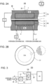
- the electrochemical hydrogen compressor 100 includes a cell 40, a voltage applicator 21, a dew point adjuster 22, and a controller 50.
- the cell 40 of the electrochemical hydrogen compressor 100 includes an electrolyte membrane 1, an anode AN, a cathode CA, a cathode separator 5C, and an anode separator 5A.
- the electrolyte membrane 1 is a membrane having a pair of principal surfaces and having proton (H + ) conductivity.
- the electrolyte membrane 1 may have any structure so long as it has proton conductivity.
- Examples of the electrolyte membrane 1 include a fluorine-based polymer electrolyte membrane and a hydrocarbon-based electrolyte membrane.
- Specific examples of the electrolyte membrane 1 include, but not limited to, Nafion (registered trademark, manufactured by DuPont) and Aciplex (registered trademark, manufactured by Asahi Kasei Corporation).
- the cathode CA is disposed on a first one of the principal surfaces of the electrolyte membrane 1.
- the anode AN is disposed on a second one of the principal surfaces of the electrolyte membrane 1.
- the anode AN includes the anode gas diffuser plate 31, an anode catalyst layer 2A, and an anode gas diffusion layer 3A.
- the cathode CA includes a cathode catalyst layer 2C and a cathode gas diffusion layer 3C.
- the cathode catalyst layer 2C is disposed on the first one of the principal surfaces of the electrolyte membrane 1.
- the cathode catalyst layer 2C may contain, for example, Pt as a catalyst metal, but this is not a limitation.
- a sealing member is disposed so as to surround the cathode catalyst layer 2C in plan view, and the hydrogen-containing gas in the cathode CA is appropriately sealed in by the sealing member.
- the anode catalyst layer 2A is disposed on the second one of the principal surfaces of the electrolyte membrane 1.
- the anode catalyst layer 2A may contain, for example, platinum (Pt) as a catalyst metal, but this is not a limitation.
- a sealing member is disposed so as to surround the anode catalyst layer 2A in plan view, and the hydrogen-containing gas in the anode AN is appropriately sealed in by the sealing member.
- any of various catalyst preparation methods may be used for the cathode catalyst layer 2C and the anode catalyst layer 2A, and no particular limitation is imposed on the catalyst preparation method.
- carriers of the catalysts include electrically conductive oxide powders and carbon-based powders.
- the carbon-based powder include graphite powder, carbon black powder, and electrically conductive activated carbon powder.
- a method such as powder mixing or liquid phase mixing may be used.
- the liquid phase mixing include a method in which a carrier such as carbon is dispersed in a catalyst component colloidal solution so that the catalyst component adsorbs on the carrier.
- the supporting state of the catalyst metal such as platinum supported on the carrier.
- the catalyst metal may be formed into fine particles, and the fine particles may be highly dispersed and supported on the carrier.
- the anode gas diffusion layer 3A is disposed on the anode catalyst layer 2A through the anode gas diffuser plate 31.
- the anode gas diffusion layer 3A is formed of, for example, a porous material and has corrosion resistance, electrical conductivity, and gas diffusibility.
- the anode gas diffusion layer 3A is formed of a highly rigid material that can prevent the displacement and deformation of components caused by the differential pressure between the anode AN and the cathode CA during the hydrogen compression operation of the electrochemical hydrogen compressor 100.
- the anode separator 5A is disposed so as to cover a first principal surface of the anode gas diffusion layer 3A and its side surface. Specifically, the anode gas diffusion layer 3A is housed in a recess in a central portion of the anode separator 5A.
- An anode flow channel 6 having, for example, a serpentine shape is formed on a principal surface of the anode separator 5A that is in contact with the anode gas diffusion layer 3A. Therefore, the hydrogen-containing gas flowing from the outside through an anode gas introduction channel 26 into an anode inlet 6 IN passes through the anode flow channel 6 disposed between the anode inlet 6 IN and an anode outlet 6 OUT .
- part of the hydrogen-containing gas flowing through the anode flow channel 6 is supplied to the anode gas diffusion layer 3A.
- the hydrogen-containing gas passing through the anode outlet 6 OUT is discharged to the outside through an anode gas discharge channel 27.
- the anode flow channel 6 may be formed by forming a slit hole having the serpentine shape in a plate member different from the anode separator 5A and joining them integrally or may be formed by forming a channel groove having the serpentine shape on the principal surface of the anode separator 5A.
- the anode flow channel 6 is not necessarily formed as a flow channel having a serpentine shape.
- the anode flow channel 6 may be composed of a plurality of linear flow channels.
- the anode separator 5A is formed from, for example, a metal member and has corrosion resistance and electrical conductivity.
- a metal member For example, titanium plated with platinum may be used as the material of the anode separator 5A.
- the electrochemical hydrogen compressor 100 may include the anode gas diffuser plate 31 having a circular shape.
- the anode gas diffusion plate 31 includes: a circular central portion 31A in contact with a second principal surface of the anode gas diffusion layer 3A and with the anode catalyst layer 2A; and a circular annular circumferential portion 31B in contact with the anode separator 5A and with the electrolyte membrane 1.
- vent holes are formed in the central portion 31A of the anode gas diffuser plate 31. Therefore, the hydrogen-containing gas can pass between the anode catalyst layer 2A and the anode gas diffusion layer 3A through the vent holes.
- the vent holes may be, for example, openings having a size of several tens of micrometers and evenly spaced at intervals of several tens of micrometers, but the size of the vent holes and the intervals therebetween are not limited thereto.
- These vent holes can be formed by, for example, laser processing.
- the anode gas diffuser plate 31 is formed from, for example, a metal plate and has corrosion resistance and electrical conductivity.
- a titanium plate plated with platinum may be used for the anode gas diffuser plate 31.
- An unillustrated circular annular sealing member is disposed on the circumferential portion 31B (flat portion) of the anode gas diffuser plate 31 through the electrolyte membrane 1. Therefore, the electrolyte membrane 1 is pressed by the sealing member against the circumferential portion 31B of the anode gas diffuser plate 31.
- the sealing member used may be, for example, an O-ring.
- the anode gas diffuser plate 31 and the sealing member are merely examples, and these examples are not limitations.
- the anode gas diffuser plate 31 is formed from a circular plate, but this is not a limitation.
- the anode gas diffusion layer 3A has, for example, a rectangular shape in plan view
- the anode gas diffuser plate 31 may have a rectangular shape in plan view
- the sealing member may have a rectangular ring shape in plan view.
- the cathode gas diffusion layer 3C is disposed on the cathode catalyst layer 2C.
- the cathode gas diffusion layer 3C is formed from, for example, a porous body and has corrosion resistance, electrical conductivity, and gas diffusibility.
- the cathode gas diffusion layer 3C may be formed from a porous body, such as sintered titanium fibers plated with platinum, which has corrosion resistance and electrical conductivity.
- the cathode gas diffusion layer 3C is formed of an elastic material that resists bucking and can follow the displacement and deformation of components caused by the differential pressure between the anode AN and the cathode CA during the hydrogen compression operation of the electrochemical hydrogen compressor 100.
- the cathode separator 5C may have a closed-end circular cylindrical shape or a closed-end rectangular cylindrical shape. When the cathode separator 5C is formed from a circular cylindrical body, the cathode separator 5C can have higher resistance to gas pressure than a cathode separator 5C formed from a rectangular cylindrical body.
- the voltage applicator 21 is a device that applies a voltage between the anode AN and the cathode CA.
- the voltage applicator 21 may have any structure so long as a voltage can be applied between the anode AN and the cathode CA.
- a high potential-side terminal of the voltage applicator 21 is connected to the anode AN, and a low potential-side terminal of the voltage applicator 21 is connected to the cathode CA. In this manner, the voltage applicator 21 is used to cause a current to flow between the anode AN and the cathode CA.
- Examples of the voltage applicator 21 include a DC/DC converter and an AC/DC converter.
- the DC/DC converter is used when the voltage applicator 21 is connected to a DC power source such as a solar cell, a fuel cell, or a battery.
- the AC/DC converter is used when the voltage applicator 21 is connected to an AC power source such as a commercial power supply.
- the dew point adjuster 22 may have any structure so long as the dew point of the hydrogen-containing gas to be supplied to the anode AN can be adjusted.
- Examples of the dew point adjuster 22 include a humidifier that humidifies the hydrogen-containing gas and a condenser that condenses water vapor in the hydrogen-containing gas.
- the dew point adjustment by the humidifier is performed, for example, by adjusting the humidity using the humidifier or adjusting the ratio of the amount of the hydrogen-containing gas passing through the humidifier to the amount of the hydrogen-containing gas bypassing the humidifier.
- the adjustment of the humidity using the humidifier is performed by adjusting the amount of heating by a heater provided in the humidifier, adjusting the amount of water supplied to the humidifier, or adjusting the amount of humidified gas supplied to the humidifier.
- the hydrogen-containing gas that has bypassed the humidifier merges with the hydrogen-containing gas that has passed through the humidifier before introduction into the anode AN.
- the dew point adjustment by the condenser is performed, for example, by adjusting the amount of condensation using the condenser or adjusting the ratio of the amount of the hydrogen-containing gas passing through the condenser to the amount of the hydrogen-containing gas bypassing the condenser.
- the amount of condensation by the condenser is adjusted by adjusting the amount of cooling by a cooler provided in the condenser.
- the controller 50 controls the dew point adjuster 22 to increase the dew point of the hydrogen-containing gas to be supplied to the anode AN.
- the controller 50 may control the dew point adjuster 22 such that a humidified hydrogen-containing gas is supplied to the anode AN.
- the electrochemical hydrogen compressor 100 may be provided with an unillustrated detector that detects the temperature of the cell 40.
- the detector include, but not limited to, a thermocouple.
- the electrochemical hydrogen compressor 100 may be prepared as follows. A stack of about 10 to about 200 cells 40 each including the MEA, the anode separator 5A, and the cathode separator 5C is formed. The stack is sandwiched between end plates through current collectors and insulating plates, and the end plates are fastened with, for example, fastening rods. The number of cells 40 may be set to an appropriate number according to the operating conditions of the electrochemical hydrogen compressor 100. Sealing members such as O-rings or gaskets may be provided on both sides of each MEA in order to prevent the high-pressure gas from leaking from the electrochemical hydrogen compressor to the outside, and the sealing members and the MEA may be integrated with each other in advance.
- Sealing members such as O-rings or gaskets may be provided on both sides of each MEA in order to prevent the high-pressure gas from leaking from the electrochemical hydrogen compressor to the outside, and the sealing members and the MEA may be integrated with each other in advance.
- the electrically conductive anode separators 5A and the electrically conductive cathode separators 5C are disposed outside the respective MEAs. These separators are used to electrically connect respective adjacent MEAs in series and mechanically fix the MEAs.
- the electrochemical hydrogen compressor 100 in the present embodiment may not include a heater for heating the cell 40 or may include the heater (not shown).
- the heater may be an electric heater or a flow channel through which a heating fluid flows.
- Fig. 3 is an illustration showing an example of the hydrogen supply system including the electrochemical hydrogen compressor in the embodiment.
- the hydrogen supply system 200 includes the electrochemical hydrogen compressor 100, a gas supply 23, and a hydrogen reservoir 25.
- the illustration of the cell 40 of the electrochemical hydrogen compressor 100 in Fig. 2A is simplified, and the illustration of the voltage applicator 21 is omitted for the sake of convenience.
- the dew point adjuster 22 of the electrochemical hydrogen compressor 100 in Fig. 2A is configured to adjust the dew point of a hydrogen-containing gas (gas mixture) that is a mixture of a hydrogen-containing gas discharged from the anode outlet 6 OUT through the anode gas discharge channel 27 and a hydrogen-containing gas supplied from a hydrogen source through the anode gas introduction channel 26.
- the anode gas discharge channel 27 is a recycling flow channel for supplying the hydrogen-containing gas discharged from the anode outlet 6 OUT to the anode gas introduction channel 26 disposed upstream of the dew point adjuster 22 and the gas supply 23.
- the hydrogen supply system 200 has a structure in which the hydrogen-containing gas with the dew point adjusted by the dew point adjuster 22 is supplied to the anode inlet 6 IN through the anode gas introduction channel 26.
- this structure for recycling the hydrogen-containing gas is merely an example, and this example is not a limitation.
- the entire amount of the hydrogen-containing gas supplied to the anode inlet 6 IN through the anode gas introduction channel 26 may be compressed from the anode AN of the cell 40 to the cathode CA.
- the gas supply 23 is a device that is disposed in the anode gas introduction channel 26 and supplies the hydrogen-containing gas from the hydrogen source to the anode inlet 6 IN of the anode AN.
- the gas supply 23 may have any structure so long as it can supply the hydrogen-containing gas.
- the gas supply 23 may be a device that adjusts the flow rate of the hydrogen-containing gas flowing through the anode gas introduction channel 26.
- the gas supply 23 is composed of, for example, a booster and a flow rate control valve but may be composed of one of them. Examples of the booster include a pump.
- the hydrogen reservoir 25 is a device that stores high-pressure hydrogen (H 2 ) introduced from the cathode flow channel 7 (see Fig. 2A ) of the cathode CA through the cathode gas discharge channel 28.
- the hydrogen reservoir 25 may have any structure so long as it can store high-pressure hydrogen. Examples of the hydrogen reservoir 25 include a tank.
- the hydrogen stored in the hydrogen reservoir 25 can be supplied to an unillustrated hydrogen consumer in a timely manner by opening an unillustrated on-off valve. Examples of the hydrogen consumer include a fuel cell.
- a condenser that removes water from the high-pressure hydrogen-containing gas discharged from the cathode flow channel 7 (see Fig. 2A ) of the cathode CA before the hydrogen-containing gas flows into the hydrogen reservoir 25 may be disposed in the cathode gas discharge channel 28.
- an on-off valve may be disposed between the condenser and the cathode flow channel 7 of the cathode CA within the cathode gas discharge channel 28.
- an on-off valve and a check valve may be disposed in the anode gas discharge channel 27.
- the check valve is disposed such that the flow direction of the hydrogen-containing gas discharged from the anode outlet 6 OUT toward a connection portion between the anode gas discharge channel 27 and the anode gas introduction channel 26 coincides with the forward direction of the check valve. This can prevent the back flow of the hydrogen-containing gas in the anode gas discharge channel 27 when the on-off valve is opened.
- the following operation may be performed, for example, by causing the arithmetic circuit of the controller 50 to read a control program from the storage circuit of the controller 50. However, it is not always necessary that the controller 50 perform the following operation. The operator may perform part of the operation.
- the hydrogen-containing gas is supplied to the anode AN of the electrochemical hydrogen compressor 100 through the anode gas introduction channel 26, and electric power of the voltage applicator 21 is supplied to the electrochemical hydrogen compressor 100.
- hydrogen molecules are separated into hydrogen ions (protons) and electrons through an oxidation reaction (formula (2)) in the anode catalyst layer 2A of the electrochemical hydrogen compressor 100.
- the protons transmit through the electrolyte membrane 1 and move to the cathode catalyst layer 2C.
- the electrons move to the cathode catalyst layer 2C of the cathode through the voltage applicator 21.
- hydrogen molecules are regenerated through a reduction reaction (formula (3)).
- the electrochemical hydrogen compressor 100 by applying a voltage between the anode AN and the cathode CA, the operation that supplies the compressed hydrogen gas from the anode AN to the CA cathode is performed. In this manner, the hydrogen compressed in the cathode CA is temporarily stored in the hydrogen reservoir 25. The hydrogen stored in the hydrogen reservoir 25 is supplied to a hydrogen consumer such as a fuel cell in a timely manner.
- the efficiency of the hydrogen compression operation can be further improved as compared with conventional compressors and methods. Specifically, since the latent heat generated during condensation of water vapor and the heat generated by IR loss can be used to heat the cell of the electrochemical hydrogen compressor 100, the electrochemical hydrogen compressor 100 can be heated to a desired temperature efficiently.
- the amount of hydrogen in the hydrogen-containing gas discharged from the anode AN is about 30% of the amount of hydrogen in the hydrogen-containing gas supplied to the anode AN.
- the temperature of the cell 40 is constant.
- the amount of water vapor in the hydrogen-containing gas to be supplied to the anode AN is also about 30% of the amount of water vapor in the hydrogen-containing gas supplied to the anode AN.
- a remaining part of the water vapor is discharged from the anode AN as condensed water or moves from the anode to the cathode CA together with protons as electroosmotic water.
- the cathode CA is sealed. Then, when the temperature is constant, the amount of saturated vapor that can be present in the cathode CA is constant, and therefore surplus water vapor exceeding the amount of saturated water vapor condenses. Specifically, about 70% of the amount of water vapor in the hydrogen-containing gas supplied to the anode AN may be condensed in the cell 40.
- the latent heat generated during the condensation of water vapor can be used to increase the temperature of the cell 40.
- water vapor condensation is merely an example, and this example is not a limitation.
- the condensation of water vapor when the cathode CA is sealed has been described, but this is not a limitation.
- water vapor in hydrogen discharged from the cathode flow channel 7 tends to condensate near the discharge port of the cathode flow channel 7 so long as the temperature of the cell 40 is higher than the ambient temperature and the cathode flow channel 7 extends in a vertical direction such that the opening of its discharge port is directed upward as shown in Fig. 2A .
- the dew point adjuster 22 increases the dew point of the hydrogen-containing gas to be supplied to the anode AN when the temperature of the cell 40 increases, so that the above possibility can be reduced.
- the ratio of condensed water produced by condensation of water vapor in the hydrogen-containing gas is maintained at a high value even when the temperature of the cell 40 increases. Therefore, the electrochemical hydrogen compressor 100 and the method for operating the electrochemical hydrogen compressor 100 in the present embodiment can effectively utilize the latent heat generated during condensation of water vapor to heat the call 40 of the electrochemical hydrogen compressor 100 even when the temperature of the cell 40 increases.
- the humidified hydrogen-containing gas is supplied to the anode AN, for example, at the startup. Therefore, heating of the cell using the latent heat generated during condensation of water vapor can be effectively used at the startup.
- An electrochemical hydrogen compressor 100 in the present embodiment is the same as the electrochemical hydrogen compressor 100 in the above embodiment except for the details of the following control by the controller 50.
- the controller 50 controls the voltage applicator 21 such that part of the hydrogen in the hydrogen-containing gas supplied to the anode AN is compressed and the remaining part of the hydrogen is not compressed.
- the electrochemical hydrogen compressor 100 in the present example part of the hydrogen in the hydrogen-containing gas supplied to the anode AN is recycled as described in the above control, and the condensed water dwelling in the anode AN can be discharged to the outside of the anode AN through the action of the flow of the hydrogen-containing gas. Therefore, in the electrochemical hydrogen compressor 100 in the present example, the possibility of the occurrence of flooding in the anode AN can be lower than that when the entire amount of the hydrogen in the hydrogen-containing gas is compressed from the anode AN of the cell 40 to the cathode.
- the electrochemical hydrogen compressor 100 in the present example may be the same as the electrochemical hydrogen compressor 100 in the embodiment except for the above feature.
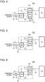
- Fig. 4 is an illustration showing an example of a hydrogen supply system including an electrochemical hydrogen compressor in a modification of the embodiment.
- the hydrogen supply system is the same as the hydrogen supply system 200 in Fig. 3 except that the electrochemical hydrogen compressor 100 includes an air cooler 30 and that the controller 50 performs the following control.
- the air cooler 30 is a device that cools the cell 40 of the electrochemical hydrogen compressor 100.
- the air cooler 30 may have any structure so long as it can air-cool the cell 40 of the electrochemical hydrogen compressor 100.
- the air cooler 30 includes an air blowing fan 30A, and air (cool air) from the air blowing fan 30A is used to cool the cell 40 from its surface.
- the controller 50 actuates the air cooler 30 when the amount of heat generated in the cell of the electrochemical hydrogen compressor 100 increases.
- the temperature of the cell of the electrochemical hydrogen compressor 100 can be controlled by air cooling more simply than in a structure in which cooling water, for example, is circulated in the cell 40.
- the results of the computations using the simple computational model verify that the temperature of the cell of the electrochemical hydrogen compressor 100 can be controlled by air cooling.
- the electrochemical hydrogen compressor 100 When the electrochemical hydrogen compressor 100 is used in a subzero environment during a suspension period in the winter, it is feared that the electrochemical hydrogen compressor 100 may freeze. However, in this case, by providing an auxiliary heater, for example, to the electrochemical hydrogen compressor 100 or by sending hot air instead of the cool air from the air blowing fan 30A to the cell 40 of the electrochemical hydrogen compressor 100, the electrochemical hydrogen compressor 100 can be prevented from freezing.
- An electrochemical hydrogen compressor 100 in the present example is the same as the electrochemical hydrogen compressor 100 in the embodiment except that the hydrogen-containing gas supplied to the anode AN contains a hydrogen-containing gas generated by water electrolysis.
- the hydrogen in the hydrogen source in Fig. 3 is generated by a water electrolysis device (not shown).
- the water electrolysis device may generate hydrogen using electric power generated from renewable energy such as sunlight. Any water electrolysis method may be used for the water electrolysis device. Examples of the water electrolysis in the water electrolysis device include solid polymer type water electrolysis.
- the hydrogen-containing gas generated by water electrolysis contains water vapor.
- the hydrogen-containing gas is in a high-humidity state with a dew point of about 80°C. Therefore, the electrochemical hydrogen compressor 100 in the present example can desirably use the hydrogen-containing gas generated by water electrolysis as the hydrogen-containing gas to be supplied to the anode AN.
- the electrochemical hydrogen compressor 100 in the present example may be the same as the electrochemical hydrogen compressor 100 in any of the embodiment, the first example of the embodiment, and the modification of the embodiment except for the above feature.
- the hydrogen in the hydrogen source in Fig. 3 is generated in a reformer (not shown).
- a reformer Any type of reforming reaction may be used in the reformer.
- the reforming reaction in the reformer include a water vapor reforming reaction, a partial oxidation reaction, and an autothermal reaction.
- the hydrocarbon compound include town gas containing methane as a main component and natural gas.
- the electrochemical hydrogen compressor 100 in the present example may be the same as the electrochemical hydrogen compressor 100 in any of the embodiment, the first and second examples of the embodiment, and the modification of the embodiment except for the above feature.
- Fig. 5 is an illustration showing an example of a hydrogen supply system including an electrochemical hydrogen compressor in a fourth example of the embodiment.
- the hydrogen supply system is the same as the hydrogen supply system 200 in Fig. 3 except that the dew point adjuster 22 of the electrochemical hydrogen compressor 100 includes a condenser 22A and that the controller 50 performs the following control.
- the condenser 22A is a device that condenses water vapor in the hydrogen-containing gas to be supplied to the anode AN.
- the condenser 22A may have any structure so long as it can condense the water vapor in the hydrogen-containing gas to be supplied to the anode AN.
- the condenser 22A may include a bubbling tank (not shown) and may be configured such that the hydrogen-containing gas passes through water in the bubbling tank.
- the condenser 22A may be configured such that the temperature of the water in the bubbling tank is maintained at a desired temperature by a temperature control mechanism (not shown).
- the dew point of the hydrogen-containing gas that have passed through the water in the bubbling tank is approximately equal to the temperature of the water in the bubbling tank. Therefore, by decreasing the water temperature to a temperature lower than the dew point of the hydrogen-containing gas before it flows into the bubbling tank, the water vapor in the hydrogen-containing gas can be condensed in the bubbling tank of the condenser 22A.
- the controller 50 controls the condenser 22A to reduce the amount of water condensed from the hydrogen-containing gas to be supplied to the anode AN.
- the condenser 22A includes the condensing tank
- the amount of water condensed from the hydrogen-containing gas can be reduced by causing the controller 50 to increase the temperature of the hydrogen-containing gas in the condensing tank to a desired temperature using the temperature control mechanism.
- the electrochemical hydrogen compressor 100 in the present example when the temperature of the cell 40 increases, the amount of water condensed from the hydrogen-containing gas in the condenser is reduced, and the dew point of the hydrogen-containing gas to be supplied to the anode AN can thereby be increased appropriately.
- the dew point of the hydrogen-containing gas and the temperature of the cell 40 can be reduced or increasing the amount of condensed water in the condenser 22A to bring the dew point of the hydrogen-containing gas and the temperature of the cell 40 close to each other, the occurrence of flooding in the anode AN and drying up of the electrolyte membrane 1 can be prevented while the latent heat generated during condensation of water vapor in the cell 40 is effectively used to heat the cell.
- the dew point is approximately the same as the temperature of the cell 40 or that the temperature of the hydrogen-containing gas supplied to the anode AN of the cell 40 is slightly higher than the temperature of the cell 40.
- the hydrogen supply system is the same as the hydrogen supply system 200 in Fig. 3 except that the dew point adjuster 22 of the electrochemical hydrogen compressor 100 includes a humidifier 22B and that the controller 50 performs the following control.
- the humidifier 22B is a device that humidifies the hydrogen-containing gas to be supplied to the anode AN.
- the humidifier 22B may have any structure so long as it can humidify the hydrogen-containing gas to be supplied to the anode AN.
- the humidifier 22B may include a bubbling tank (not shown) and may be configured such that the hydrogen-containing gas passes through water in the bubbling tank.
- the humidifier 22B may be configured such that the temperature of the water in the bubbling tank is maintained at a desired temperature using a temperature control mechanism (not shown).
- the dew point of the hydrogen-containing gas that has passed through the water in the bubbling tank is approximately equal to the temperature of the water in the bubbling tank. Therefore, by increasing the water temperature to a temperature higher than the dew point of the hydrogen-containing gas before it flows into the bubbling tank, the hydrogen-containing gas can be humidify in the bubbling tank of the humidifier 22B.
- the controller 50 controls the humidifier 22B to increase the humidity of the hydrogen-containing gas to be supplied to the anode AN.
- the humidity of the hydrogen-containing gas can be increased by causing the controller 50 to increase the temperature of the water in the bubbling tank to a desired temperature using a temperature control mechanism.
- the dew point of the hydrogen-containing gas and the temperature of the cell 40 can be decreased while the occurrence of flooding in the anode AN and drying up of the electrolyte membrane 1 can be prevented while the latent heat generated during condensation of water vapor in the cell 40 is effectively used to heat the cell.
- the dew point is approximately the same as the temperature of the cell 40 or that the temperature of the hydrogen-containing gas supplied to the anode AN of the cell 40 is slightly higher than the temperature of the cell 40.
- the dew point of the hydrogen-containing gas is adjusted to be equal to or lower than the cell temperature +5°C and that, when the temperature of the cell increases, the dew point adjuster is controlled to increase the dew point of the hydrogen-containing gas. It is more desirable that the controller controls the dew point adjuster to adjust the dew point of the hydrogen-containing gas to be equal to or lower than the temperature of the cell and that, when the temperature of the cell increases, the controller controls the dew point adjuster to increase the dew point of the hydrogen-containing gas.
- the electrochemical hydrogen compressor 100 in the present example may be the same as the electrochemical hydrogen compressor 100 in any of the embodiment, the first to third examples of the embodiment, and the modification of the embodiment except for the above feature.
Landscapes
- Chemical & Material Sciences (AREA)
- Engineering & Computer Science (AREA)
- Organic Chemistry (AREA)
- Chemical Kinetics & Catalysis (AREA)
- Electrochemistry (AREA)
- Materials Engineering (AREA)
- Metallurgy (AREA)
- Automation & Control Theory (AREA)
- Inorganic Chemistry (AREA)
- Analytical Chemistry (AREA)
- Combustion & Propulsion (AREA)
- Fuel Cell (AREA)
- Electrolytic Production Of Non-Metals, Compounds, Apparatuses Therefor (AREA)
- Hydrogen, Water And Hydrids (AREA)
- Life Sciences & Earth Sciences (AREA)
- Manufacturing & Machinery (AREA)
- Sustainable Development (AREA)
- Sustainable Energy (AREA)
- General Chemical & Material Sciences (AREA)
Claims (11)
- Compresseur d'hydrogène électrochimique comprenant :une cellule (40) comportant une membrane électrolyte (1) conductrice de protons (1) ayant une paire de surfaces principales, une cathode (CA) disposée sur une première surface parmi les surfaces principales de la membrane d'électrolyte (1), et une anode (AN) disposée sur une seconde surface parmi les surfaces principales de la membrane électrolyte (1) ;un applicateur de tension (21) configuré pour appliquer une tension entre l'anode (AN) et la cathode (CA) ;un dispositif de réglage de point de rosée (22) configuré pour régler un point de rosée d'un gaz contenant de l'hydrogène destiné à être fourni à l'anode (AN) ; etun module de commande (50),caractérisé en ce que lorsque la température de la cellule (40) augmente, le module de commande (50) est configuré pour commander au dispositif de réglage de point de rosée (22) d'augmenter le point de rosée du gaz contenant de l'hydrogène.
- Compresseur d'hydrogène électrochimique selon la revendication 1,
dans lequel, au démarrage, le module de commande (50) est configuré pour commander le dispositif de réglage de point de rosée (22) de telle sorte qu'un gaz contenant de l'hydrogène humidifié soit fourni à l'anode (AN). - Compresseur d'hydrogène électrochimique selon la revendication 1 ou 2,
dans lequel le module de commande (50) est configuré pour commander l'applicateur de tension (21) de telle sorte qu'une partie de l'hydrogène présent dans le gaz contenant de l'hydrogène soit compressée et qu'une partie restante de l'hydrogène ne soit pas compressée. - Compresseur d'hydrogène électrochimique selon l'une quelconque des revendications 1 à 3, comprenant en outre un refroidisseur (30) configuré pour refroidir la cellule (40),
dans lequel le module de commande (50) est configuré pour actionner le refroidisseur (30) lorsque la quantité de chaleur générée dans la cellule (40) augmente. - Compresseur d'hydrogène électrochimique selon l'une quelconque des revendications 1 à 4,
dans lequel le gaz contenant de l'hydrogène contient un gaz contenant de l'hydrogène généré par électrolyse de l'eau. - Compresseur d'hydrogène électrochimique selon l'une quelconque des revendications 1 à 5,
dans lequel le gaz contenant de l'hydrogène contient un gaz contenant de l'hydrogène généré par une réaction de reformage d'un composé hydrocarbure. - Compresseur d'hydrogène électrochimique selon l'une quelconque des revendications 1 à 6,dans lequel le dispositif de réglage de point de rosée (22) comporte un condenseur (22A), etdans lequel, lorsque la température de la cellule (40) augmente, le module de commande (50) est configuré pour commander au condenseur (22A) de réduire la quantité d'eau extraite du gaz contenant de l'hydrogène par condensation.
- Compresseur d'hydrogène électrochimique selon l'une quelconque des revendications 1 à 6,dans lequel le dispositif de réglage de point de rosée (22) comporte un humidificateur (22B), etdans lequel, lorsque la température de la cellule (40) augmente, le module de commande (50) est configuré pour commander à l'humidificateur (22B) d'augmenter l'humidité du gaz contenant de l'hydrogène.
- Compresseur d'hydrogène électrochimique selon l'une quelconque des revendications 1 à 8,dans lequel le module de commande (50) est configuré pour commander au dispositif de réglage de point de rosée (22B) de régler le point de rosée du gaz contenant de l'hydrogène pour qu'il soit inférieur ou égal à la température de la cellule + 5 °C, etdans lequel, lorsque la température de la cellule (40) augmente, le module de commande (50) est configuré pour commander au dispositif de réglage de point de rosée (22) d'augmenter le point de rosée du gaz contenant de l'hydrogène.
- Compresseur d'hydrogène électrochimique selon l'une quelconque des revendications 1 à 8,dans lequel le module de commande (50) est configuré pour commander au dispositif de réglage de point de rosée (22B) de régler le point de rosée du gaz contenant de l'hydrogène pour qu'il soit inférieur ou égal à la température de la cellule (40), etdans lequel, lorsque la température de la cellule (40) augmente, le module de commande (50) est configuré pour commander au dispositif de réglage de point de rosée (22) d'augmenter le point de rosée du gaz contenant de l'hydrogène.
- Procédé de fonctionnement d'un compresseur d'hydrogène électrochimique, le procédé comprenant :une étape (a) consistant à appliquer une tension entre une anode (AN) d'une cellule (40) et une cathode (CA) de la cellule (40) afin de fournir un gaz hydrogène comprimé de l'anode (AN) à la cathode (CA), la cellule (40) comportant une membrane électrolyte (1) conductrice de protons ayant une paire de surfaces principales, la cathode (CA) disposée sur une première surface parmi les surfaces principales de la membrane électrolyte (1), et l'anode (AN) disposée sur une seconde surface parmi les surfaces principales de la membrane électrolyte (1) ; etcaractérisé par l'étape (b) qui consiste, lorsque la température de la cellule (40) augmente à l'étape (a), à augmenter le point de rosée d'un gaz contenant de l'hydrogène destiné à être fourni à l'anode (AN).
Applications Claiming Priority (2)
| Application Number | Priority Date | Filing Date | Title |
|---|---|---|---|
| JP2018207974 | 2018-11-05 | ||
| PCT/JP2019/036272 WO2020095543A1 (fr) | 2018-11-05 | 2019-09-17 | Appareil de compression électrochimique d'hydrogène et procédé de fonctionnement d'un appareil de compression électrochimique d'hydrogène |
Publications (3)
| Publication Number | Publication Date |
|---|---|
| EP3879005A1 EP3879005A1 (fr) | 2021-09-15 |
| EP3879005A4 EP3879005A4 (fr) | 2022-01-05 |
| EP3879005B1 true EP3879005B1 (fr) | 2025-01-15 |
Family
ID=70611239
Family Applications (1)
| Application Number | Title | Priority Date | Filing Date |
|---|---|---|---|
| EP19882291.8A Active EP3879005B1 (fr) | 2018-11-05 | 2019-09-17 | Appareil de compression électrochimique d'hydrogène et méthode pour opérer un appareil de compression électrochimique d'hydrogène |
Country Status (5)
| Country | Link |
|---|---|
| US (1) | US11598013B2 (fr) |
| EP (1) | EP3879005B1 (fr) |
| JP (1) | JP6765060B1 (fr) |
| CN (1) | CN111417746B9 (fr) |
| WO (1) | WO2020095543A1 (fr) |
Families Citing this family (16)
| Publication number | Priority date | Publication date | Assignee | Title |
|---|---|---|---|---|
| CN113994028B (zh) * | 2020-05-25 | 2025-02-11 | 松下知识产权经营株式会社 | 氢系统 |
| JP7138312B2 (ja) * | 2020-07-14 | 2022-09-16 | パナソニックIpマネジメント株式会社 | 水素システムおよび水素システムの運転方法 |
| EP4219394A4 (fr) * | 2020-09-25 | 2024-09-04 | Panasonic Intellectual Property Management Co., Ltd. | Dispositif de compression |
| JP7292326B2 (ja) * | 2020-12-15 | 2023-06-16 | 本田技研工業株式会社 | 電気化学式水素昇圧システム |
| CN114639852B (zh) | 2020-12-15 | 2024-04-16 | 本田技研工业株式会社 | 电化学式氢升压系统 |
| KR102447597B1 (ko) * | 2021-01-08 | 2022-09-27 | 중앙대학교 산학협력단 | 전기화학적 수소 압축기 |
| US11926906B2 (en) * | 2021-03-15 | 2024-03-12 | Air Products And Chemicals, Inc. | Process and apparatus for compressing hydrogen gas in a centrifugal compressor |
| JP7122545B1 (ja) * | 2021-04-20 | 2022-08-22 | パナソニックIpマネジメント株式会社 | 圧縮装置および圧縮装置の制御方法 |
| WO2022224480A1 (fr) * | 2021-04-20 | 2022-10-27 | パナソニックIpマネジメント株式会社 | Dispositif de compression et procédé de commande pour dispositif de compression |
| JP7122546B1 (ja) * | 2021-04-20 | 2022-08-22 | パナソニックIpマネジメント株式会社 | 圧縮装置および圧縮装置の制御方法 |
| JP7731844B2 (ja) * | 2021-05-03 | 2025-09-01 | ブルーム エネルギー コーポレイション | 水素ポンプを含む固体酸化物型電解槽システム、及び固体酸化物型電解槽システムを動作させる方法 |
| CN115411304B (zh) * | 2021-05-27 | 2025-10-28 | 国家能源投资集团有限责任公司 | 燃料电池用氢气的纯化系统及纯化方法 |
| CN114284523B (zh) * | 2021-12-24 | 2024-01-19 | 上海重塑能源科技有限公司 | 一种可控露点温度的燃料电池阳极循环路及其控制方法 |
| KR20230111592A (ko) | 2022-01-18 | 2023-07-25 | 블룸 에너지 코퍼레이션 | Soec 시스템의 대기 작동을 위한 압축기 통합 및 안전한 작동 시작 |
| JP7591016B2 (ja) * | 2022-10-26 | 2024-11-27 | 本田技研工業株式会社 | 水電解システム |
| JP7826258B2 (ja) * | 2023-09-20 | 2026-03-09 | 株式会社東芝 | 電気化学反応装置および電気化学反応装置の運転方法 |
Family Cites Families (21)
| Publication number | Priority date | Publication date | Assignee | Title |
|---|---|---|---|---|
| US8282811B2 (en) * | 2001-08-29 | 2012-10-09 | Giner Electrochemical Systems, Llc | Method and system for producing high-pressure hydrogen |
| JP2003178780A (ja) * | 2001-12-11 | 2003-06-27 | Matsushita Electric Ind Co Ltd | 高分子電解質型燃料電池システム、および高分子電解質型燃料電池の運転方法 |
| JP2003185096A (ja) * | 2001-12-18 | 2003-07-03 | Tokyo Gas Co Ltd | 水素供給設備 |
| JP4523298B2 (ja) * | 2004-02-10 | 2010-08-11 | 株式会社豊田中央研究所 | 燃料電池システム及びその発電方法 |
| JP4034804B2 (ja) * | 2004-12-28 | 2008-01-16 | 松下電器産業株式会社 | 高分子電解質型燃料電池発電システム |
| JP6222958B2 (ja) * | 2013-03-27 | 2017-11-01 | 大阪瓦斯株式会社 | 熱電併給システム用固体高分子型燃料電池の運転方法及び熱電併給システム用固体高分子型燃料電池 |
| JP6299027B2 (ja) | 2013-12-16 | 2018-03-28 | 国立大学法人山梨大学 | 水素精製昇圧システム及びその運転方法 |
| AU2015284224B2 (en) * | 2014-07-03 | 2019-05-16 | Nuvera Fuel Cells, LLC | System and method for regenerating absorber bed for drying compressed humidified hydrogen |
| JP6291402B2 (ja) * | 2014-11-12 | 2018-03-14 | 東京瓦斯株式会社 | 圧縮水素供給装置 |
| JP6500227B2 (ja) * | 2015-05-13 | 2019-04-17 | パナソニックIpマネジメント株式会社 | ガス生成装置とガス生成方法 |
| JP6811444B2 (ja) * | 2016-02-16 | 2021-01-13 | パナソニックIpマネジメント株式会社 | 電気化学式水素ポンプ |
| JP2018104731A (ja) * | 2016-12-22 | 2018-07-05 | パナソニックIpマネジメント株式会社 | 電気化学装置及びその運転方法 |
| JP6795439B2 (ja) * | 2017-03-28 | 2020-12-02 | 東京瓦斯株式会社 | 圧縮水素製造システム |
| CN107435814B (zh) * | 2017-07-12 | 2019-09-17 | 鲁西新能源装备集团有限公司 | 一种降低高纯氢气管束式集装箱内气瓶露点的方法 |
| JP7220368B2 (ja) * | 2017-12-01 | 2023-02-10 | パナソニックIpマネジメント株式会社 | 水素供給システム |
| JP2019119654A (ja) * | 2018-01-10 | 2019-07-22 | パナソニックIpマネジメント株式会社 | 電気化学式水素ポンプ |
| JP7122541B2 (ja) * | 2018-04-16 | 2022-08-22 | パナソニックIpマネジメント株式会社 | 電気化学式水素ポンプおよび電気化学式水素ポンプの運転方法 |
| JP7162258B2 (ja) * | 2018-05-30 | 2022-10-28 | パナソニックIpマネジメント株式会社 | 水素供給システムおよび水素供給システムの運転方法 |
| JP7249588B2 (ja) * | 2018-06-14 | 2023-03-31 | パナソニックIpマネジメント株式会社 | 電気化学式水素ポンプ |
| JP7209221B2 (ja) * | 2018-07-23 | 2023-01-20 | パナソニックIpマネジメント株式会社 | 電気化学式水素ポンプ |
| CN113366152B (zh) * | 2019-12-24 | 2025-03-07 | 松下知识产权经营株式会社 | 电化学式氢泵及其控制方法 |
-
2019
- 2019-09-17 CN CN201980004296.5A patent/CN111417746B9/zh active Active
- 2019-09-17 JP JP2020539875A patent/JP6765060B1/ja active Active
- 2019-09-17 WO PCT/JP2019/036272 patent/WO2020095543A1/fr not_active Ceased
- 2019-09-17 EP EP19882291.8A patent/EP3879005B1/fr active Active
-
2020
- 2020-07-14 US US16/928,047 patent/US11598013B2/en active Active
Also Published As
| Publication number | Publication date |
|---|---|
| JPWO2020095543A1 (ja) | 2021-02-15 |
| EP3879005A1 (fr) | 2021-09-15 |
| US11598013B2 (en) | 2023-03-07 |
| WO2020095543A1 (fr) | 2020-05-14 |
| CN111417746B9 (zh) | 2024-07-05 |
| EP3879005A4 (fr) | 2022-01-05 |
| JP6765060B1 (ja) | 2020-10-07 |
| CN111417746A (zh) | 2020-07-14 |
| CN111417746B (zh) | 2024-05-03 |
| US20200343567A1 (en) | 2020-10-29 |
Similar Documents
| Publication | Publication Date | Title |
|---|---|---|
| EP3879005B1 (fr) | Appareil de compression électrochimique d'hydrogène et méthode pour opérer un appareil de compression électrochimique d'hydrogène | |
| US12139805B2 (en) | Hydrogen system | |
| US7045233B2 (en) | Method and apparatus for electrochemical compression and expansion of hydrogen in a fuel cell system | |
| US7132182B2 (en) | Method and apparatus for electrochemical compression and expansion of hydrogen in a fuel cell system | |
| CN110387556A (zh) | 电化学式氢气泵和电化学式氢气泵的运行方法 | |
| US20240017210A1 (en) | Compressor device and method for controlling compressor device | |
| US20240011174A1 (en) | Compressor device and method for controlling compressor device | |
| JP7002044B2 (ja) | 電気化学式水素ポンプ及びその制御方法 | |
| JP2020090695A (ja) | 電気化学式水素圧縮システム | |
| WO2022224480A1 (fr) | Dispositif de compression et procédé de commande pour dispositif de compression | |
| WO2022224481A1 (fr) | Appareil de compression et procédé de commande d'appareil de compression |
Legal Events
| Date | Code | Title | Description |
|---|---|---|---|
| STAA | Information on the status of an ep patent application or granted ep patent |
Free format text: STATUS: THE INTERNATIONAL PUBLICATION HAS BEEN MADE |
|
| PUAI | Public reference made under article 153(3) epc to a published international application that has entered the european phase |
Free format text: ORIGINAL CODE: 0009012 |
|
| STAA | Information on the status of an ep patent application or granted ep patent |
Free format text: STATUS: REQUEST FOR EXAMINATION WAS MADE |
|
| 17P | Request for examination filed |
Effective date: 20210408 |
|
| AK | Designated contracting states |
Kind code of ref document: A1 Designated state(s): AL AT BE BG CH CY CZ DE DK EE ES FI FR GB GR HR HU IE IS IT LI LT LU LV MC MK MT NL NO PL PT RO RS SE SI SK SM TR |
|
| A4 | Supplementary search report drawn up and despatched |
Effective date: 20211203 |
|
| RIC1 | Information provided on ipc code assigned before grant |
Ipc: C25B 15/08 20060101ALI20211129BHEP Ipc: C25B 15/027 20210101ALI20211129BHEP Ipc: B01D 53/32 20060101ALI20211129BHEP Ipc: C25B 9/00 20210101ALI20211129BHEP Ipc: C25B 1/02 20060101ALI20211129BHEP Ipc: C01B 3/00 20060101ALI20211129BHEP Ipc: C25B 15/02 20210101AFI20211129BHEP |
|
| DAV | Request for validation of the european patent (deleted) | ||
| DAX | Request for extension of the european patent (deleted) | ||
| RIC1 | Information provided on ipc code assigned before grant |
Ipc: C25B 15/08 20060101ALI20240808BHEP Ipc: C25B 15/027 20210101ALI20240808BHEP Ipc: B01D 53/32 20060101ALI20240808BHEP Ipc: C25B 9/00 20210101ALI20240808BHEP Ipc: C25B 1/02 20060101ALI20240808BHEP Ipc: C01B 3/00 20060101ALI20240808BHEP Ipc: C25B 15/02 20210101AFI20240808BHEP |
|
| GRAP | Despatch of communication of intention to grant a patent |
Free format text: ORIGINAL CODE: EPIDOSNIGR1 |
|
| STAA | Information on the status of an ep patent application or granted ep patent |
Free format text: STATUS: GRANT OF PATENT IS INTENDED |
|
| INTG | Intention to grant announced |
Effective date: 20240924 |
|
| GRAS | Grant fee paid |
Free format text: ORIGINAL CODE: EPIDOSNIGR3 |
|
| GRAA | (expected) grant |
Free format text: ORIGINAL CODE: 0009210 |
|
| STAA | Information on the status of an ep patent application or granted ep patent |
Free format text: STATUS: THE PATENT HAS BEEN GRANTED |
|
| AK | Designated contracting states |
Kind code of ref document: B1 Designated state(s): AL AT BE BG CH CY CZ DE DK EE ES FI FR GB GR HR HU IE IS IT LI LT LU LV MC MK MT NL NO PL PT RO RS SE SI SK SM TR |
|
| REG | Reference to a national code |
Ref country code: CH Ref legal event code: EP Ref country code: GB Ref legal event code: FG4D |
|
| REG | Reference to a national code |
Ref country code: DE Ref legal event code: R096 Ref document number: 602019064976 Country of ref document: DE |
|
| REG | Reference to a national code |
Ref country code: IE Ref legal event code: FG4D |
|
| REG | Reference to a national code |
Ref country code: NL Ref legal event code: MP Effective date: 20250115 |
|
| PG25 | Lapsed in a contracting state [announced via postgrant information from national office to epo] |
Ref country code: NL Free format text: LAPSE BECAUSE OF FAILURE TO SUBMIT A TRANSLATION OF THE DESCRIPTION OR TO PAY THE FEE WITHIN THE PRESCRIBED TIME-LIMIT Effective date: 20250115 |
|
| PG25 | Lapsed in a contracting state [announced via postgrant information from national office to epo] |
Ref country code: RS Free format text: LAPSE BECAUSE OF FAILURE TO SUBMIT A TRANSLATION OF THE DESCRIPTION OR TO PAY THE FEE WITHIN THE PRESCRIBED TIME-LIMIT Effective date: 20250415 |
|
| PG25 | Lapsed in a contracting state [announced via postgrant information from national office to epo] |
Ref country code: FI Free format text: LAPSE BECAUSE OF FAILURE TO SUBMIT A TRANSLATION OF THE DESCRIPTION OR TO PAY THE FEE WITHIN THE PRESCRIBED TIME-LIMIT Effective date: 20250115 |
|
| PG25 | Lapsed in a contracting state [announced via postgrant information from national office to epo] |
Ref country code: PL Free format text: LAPSE BECAUSE OF FAILURE TO SUBMIT A TRANSLATION OF THE DESCRIPTION OR TO PAY THE FEE WITHIN THE PRESCRIBED TIME-LIMIT Effective date: 20250115 |
|
| PG25 | Lapsed in a contracting state [announced via postgrant information from national office to epo] |
Ref country code: ES Free format text: LAPSE BECAUSE OF FAILURE TO SUBMIT A TRANSLATION OF THE DESCRIPTION OR TO PAY THE FEE WITHIN THE PRESCRIBED TIME-LIMIT Effective date: 20250115 |
|
| REG | Reference to a national code |
Ref country code: LT Ref legal event code: MG9D |
|
| PG25 | Lapsed in a contracting state [announced via postgrant information from national office to epo] |
Ref country code: IS Free format text: LAPSE BECAUSE OF FAILURE TO SUBMIT A TRANSLATION OF THE DESCRIPTION OR TO PAY THE FEE WITHIN THE PRESCRIBED TIME-LIMIT Effective date: 20250515 Ref country code: NO Free format text: LAPSE BECAUSE OF FAILURE TO SUBMIT A TRANSLATION OF THE DESCRIPTION OR TO PAY THE FEE WITHIN THE PRESCRIBED TIME-LIMIT Effective date: 20250415 |
|
| REG | Reference to a national code |
Ref country code: AT Ref legal event code: MK05 Ref document number: 1759913 Country of ref document: AT Kind code of ref document: T Effective date: 20250115 |
|
| PG25 | Lapsed in a contracting state [announced via postgrant information from national office to epo] |
Ref country code: HR Free format text: LAPSE BECAUSE OF FAILURE TO SUBMIT A TRANSLATION OF THE DESCRIPTION OR TO PAY THE FEE WITHIN THE PRESCRIBED TIME-LIMIT Effective date: 20250115 |
|
| PG25 | Lapsed in a contracting state [announced via postgrant information from national office to epo] |
Ref country code: LV Free format text: LAPSE BECAUSE OF FAILURE TO SUBMIT A TRANSLATION OF THE DESCRIPTION OR TO PAY THE FEE WITHIN THE PRESCRIBED TIME-LIMIT Effective date: 20250115 Ref country code: PT Free format text: LAPSE BECAUSE OF FAILURE TO SUBMIT A TRANSLATION OF THE DESCRIPTION OR TO PAY THE FEE WITHIN THE PRESCRIBED TIME-LIMIT Effective date: 20250515 |
|
| PG25 | Lapsed in a contracting state [announced via postgrant information from national office to epo] |
Ref country code: GR Free format text: LAPSE BECAUSE OF FAILURE TO SUBMIT A TRANSLATION OF THE DESCRIPTION OR TO PAY THE FEE WITHIN THE PRESCRIBED TIME-LIMIT Effective date: 20250416 Ref country code: BG Free format text: LAPSE BECAUSE OF FAILURE TO SUBMIT A TRANSLATION OF THE DESCRIPTION OR TO PAY THE FEE WITHIN THE PRESCRIBED TIME-LIMIT Effective date: 20250115 |
|
| PG25 | Lapsed in a contracting state [announced via postgrant information from national office to epo] |
Ref country code: AT Free format text: LAPSE BECAUSE OF FAILURE TO SUBMIT A TRANSLATION OF THE DESCRIPTION OR TO PAY THE FEE WITHIN THE PRESCRIBED TIME-LIMIT Effective date: 20250115 |
|
| PG25 | Lapsed in a contracting state [announced via postgrant information from national office to epo] |
Ref country code: SE Free format text: LAPSE BECAUSE OF FAILURE TO SUBMIT A TRANSLATION OF THE DESCRIPTION OR TO PAY THE FEE WITHIN THE PRESCRIBED TIME-LIMIT Effective date: 20250115 |
|
| PG25 | Lapsed in a contracting state [announced via postgrant information from national office to epo] |
Ref country code: SM Free format text: LAPSE BECAUSE OF FAILURE TO SUBMIT A TRANSLATION OF THE DESCRIPTION OR TO PAY THE FEE WITHIN THE PRESCRIBED TIME-LIMIT Effective date: 20250115 |
|
| PG25 | Lapsed in a contracting state [announced via postgrant information from national office to epo] |
Ref country code: DK Free format text: LAPSE BECAUSE OF FAILURE TO SUBMIT A TRANSLATION OF THE DESCRIPTION OR TO PAY THE FEE WITHIN THE PRESCRIBED TIME-LIMIT Effective date: 20250115 |
|
| PGFP | Annual fee paid to national office [announced via postgrant information from national office to epo] |
Ref country code: DE Payment date: 20250919 Year of fee payment: 7 |
|
| PG25 | Lapsed in a contracting state [announced via postgrant information from national office to epo] |
Ref country code: IT Free format text: LAPSE BECAUSE OF FAILURE TO SUBMIT A TRANSLATION OF THE DESCRIPTION OR TO PAY THE FEE WITHIN THE PRESCRIBED TIME-LIMIT Effective date: 20250115 |
|
| REG | Reference to a national code |
Ref country code: DE Ref legal event code: R097 Ref document number: 602019064976 Country of ref document: DE |
|
| PG25 | Lapsed in a contracting state [announced via postgrant information from national office to epo] |
Ref country code: CZ Free format text: LAPSE BECAUSE OF FAILURE TO SUBMIT A TRANSLATION OF THE DESCRIPTION OR TO PAY THE FEE WITHIN THE PRESCRIBED TIME-LIMIT Effective date: 20250115 Ref country code: EE Free format text: LAPSE BECAUSE OF FAILURE TO SUBMIT A TRANSLATION OF THE DESCRIPTION OR TO PAY THE FEE WITHIN THE PRESCRIBED TIME-LIMIT Effective date: 20250115 |
|
| PG25 | Lapsed in a contracting state [announced via postgrant information from national office to epo] |
Ref country code: RO Free format text: LAPSE BECAUSE OF FAILURE TO SUBMIT A TRANSLATION OF THE DESCRIPTION OR TO PAY THE FEE WITHIN THE PRESCRIBED TIME-LIMIT Effective date: 20250115 |
|
| PG25 | Lapsed in a contracting state [announced via postgrant information from national office to epo] |
Ref country code: SK Free format text: LAPSE BECAUSE OF FAILURE TO SUBMIT A TRANSLATION OF THE DESCRIPTION OR TO PAY THE FEE WITHIN THE PRESCRIBED TIME-LIMIT Effective date: 20250115 |
|
| PLBE | No opposition filed within time limit |
Free format text: ORIGINAL CODE: 0009261 |
|
| STAA | Information on the status of an ep patent application or granted ep patent |
Free format text: STATUS: NO OPPOSITION FILED WITHIN TIME LIMIT |
|
| 26N | No opposition filed |
Effective date: 20251016 |