EP3879077A1 - Turbine à vapeur dotée d'une structure d'ajout de vapeur et son procédé de fonctionnement - Google Patents
Turbine à vapeur dotée d'une structure d'ajout de vapeur et son procédé de fonctionnement Download PDFInfo
- Publication number
- EP3879077A1 EP3879077A1 EP19881794.2A EP19881794A EP3879077A1 EP 3879077 A1 EP3879077 A1 EP 3879077A1 EP 19881794 A EP19881794 A EP 19881794A EP 3879077 A1 EP3879077 A1 EP 3879077A1
- Authority
- EP
- European Patent Office
- Prior art keywords
- steam
- inner casing
- supplementing
- rotor
- chamber
- Prior art date
- Legal status (The legal status is an assumption and is not a legal conclusion. Google has not performed a legal analysis and makes no representation as to the accuracy of the status listed.)
- Granted
Links
Images



Classifications
-
- F—MECHANICAL ENGINEERING; LIGHTING; HEATING; WEAPONS; BLASTING
- F01—MACHINES OR ENGINES IN GENERAL; ENGINE PLANTS IN GENERAL; STEAM ENGINES
- F01D—NON-POSITIVE DISPLACEMENT MACHINES OR ENGINES, e.g. STEAM TURBINES
- F01D25/00—Component parts, details, or accessories, not provided for in, or of interest apart from, other groups
- F01D25/08—Cooling; Heating; Heat-insulation
- F01D25/12—Cooling
-
- F—MECHANICAL ENGINEERING; LIGHTING; HEATING; WEAPONS; BLASTING
- F01—MACHINES OR ENGINES IN GENERAL; ENGINE PLANTS IN GENERAL; STEAM ENGINES
- F01D—NON-POSITIVE DISPLACEMENT MACHINES OR ENGINES, e.g. STEAM TURBINES
- F01D25/00—Component parts, details, or accessories, not provided for in, or of interest apart from, other groups
- F01D25/04—Antivibration arrangements
-
- F—MECHANICAL ENGINEERING; LIGHTING; HEATING; WEAPONS; BLASTING
- F01—MACHINES OR ENGINES IN GENERAL; ENGINE PLANTS IN GENERAL; STEAM ENGINES
- F01D—NON-POSITIVE DISPLACEMENT MACHINES OR ENGINES, e.g. STEAM TURBINES
- F01D25/00—Component parts, details, or accessories, not provided for in, or of interest apart from, other groups
- F01D25/08—Cooling; Heating; Heat-insulation
- F01D25/14—Casings modified therefor
-
- F—MECHANICAL ENGINEERING; LIGHTING; HEATING; WEAPONS; BLASTING
- F01—MACHINES OR ENGINES IN GENERAL; ENGINE PLANTS IN GENERAL; STEAM ENGINES
- F01D—NON-POSITIVE DISPLACEMENT MACHINES OR ENGINES, e.g. STEAM TURBINES
- F01D25/00—Component parts, details, or accessories, not provided for in, or of interest apart from, other groups
- F01D25/24—Casings; Casing parts, e.g. diaphragms, casing fastenings
- F01D25/26—Double casings; Measures against temperature strain in casings
-
- F—MECHANICAL ENGINEERING; LIGHTING; HEATING; WEAPONS; BLASTING
- F01—MACHINES OR ENGINES IN GENERAL; ENGINE PLANTS IN GENERAL; STEAM ENGINES
- F01D—NON-POSITIVE DISPLACEMENT MACHINES OR ENGINES, e.g. STEAM TURBINES
- F01D3/00—Machines or engines with axial-thrust balancing effected by working-fluid
- F01D3/04—Machines or engines with axial-thrust balancing effected by working-fluid axial thrust being compensated by thrust-balancing dummy piston or the like
-
- F—MECHANICAL ENGINEERING; LIGHTING; HEATING; WEAPONS; BLASTING
- F05—INDEXING SCHEMES RELATING TO ENGINES OR PUMPS IN VARIOUS SUBCLASSES OF CLASSES F01-F04
- F05D—INDEXING SCHEME FOR ASPECTS RELATING TO NON-POSITIVE-DISPLACEMENT MACHINES OR ENGINES, GAS-TURBINES OR JET-PROPULSION PLANTS
- F05D2220/00—Application
- F05D2220/30—Application in turbines
- F05D2220/31—Application in turbines in steam turbines
-
- F—MECHANICAL ENGINEERING; LIGHTING; HEATING; WEAPONS; BLASTING
- F05—INDEXING SCHEMES RELATING TO ENGINES OR PUMPS IN VARIOUS SUBCLASSES OF CLASSES F01-F04
- F05D—INDEXING SCHEME FOR ASPECTS RELATING TO NON-POSITIVE-DISPLACEMENT MACHINES OR ENGINES, GAS-TURBINES OR JET-PROPULSION PLANTS
- F05D2260/00—Function
- F05D2260/20—Heat transfer, e.g. cooling
- F05D2260/232—Heat transfer, e.g. cooling characterized by the cooling medium
- F05D2260/2322—Heat transfer, e.g. cooling characterized by the cooling medium steam
Definitions
- Embodiments of the present disclosure relate to a steam turbine having a steam supplementing structure and an operating method therefor.
- a steam turbine is a rotary steam-powered machine, customarily comprising a rotatably mounted rotor fitted with blades, the rotor being installed inside a casing shell.
- the rotor When heated and pressurized steam is flowing through a flow space formed by the casing shell, the rotor is set in rotation via the blades.
- the patent CN200580033477.9 discloses a steam turbine (as shown in Fig. 1 ), wherein the steam turbine comprises: an outer casing 2 and an inner casing 3, wherein the outer casing 2 and the inner casing 3 are provided with a live steam feed channel 10; and a rotor 5 rotatably mounted inside the inner casing 3, the rotor 5 having a thrust balancing piston 4 and comprising a plurality of impeller blades 7; wherein a plurality of guide blades 8 are arranged on the inner casing 3 in such a manner that the plurality of guide blades 8 form, in a flow direction 11, a steam flow channel 9 comprising one or more blade stages; after traversing one blade stage, the steam flows through a return channel 14 within the inner casing 3 into a chamber 15 between the inner casing 3 and the outer casing 2, and then from the chamber 15, flows through a feed channel 16 within the inner casing 3 into a thrust balancing piston antechamber 12 that is disposed in an axial direction 17 between
- the live steam feed is shown symbolically by the arrow 13; the live steam admitted into the live steam feed channel 10 flows for the most part along the flow direction into the flow channel 9, while a smaller part flows as leakage steam into a sealed chamber 18 disposed between the rotor 5 and the inner casing 3.
- the leakage steam flows substantially along a counter direction 19.
- the steam in the sealed chamber 18 flows through a cross-return channel 20 arranged in the inner casing 3 into an inflow cavity 26 which is disposed downstream of one blade stage, wherein symbols 21, 22 represent two turns of the cross-return channel 20; meanwhile, supplemental steam flows into the inflow cavity 26 via a load inlet pipe 23 which extends through the outer casing 2 and the inner casing 3.
- the return channel 14, after traversing one return blade stage 24, is connected to the flow channel 9; and the cross-return channel 20, after traversing one cross-return blade stage 25, is connected to the flow channel 9, wherein the cross-return blade stage 25 is disposed downstream of the return blade stage 24 along the flow direction 11 of the flow channel 9.
- the steam supplementing pipeline 24' and the cross-return channel 20' are connected in the inner casing 3' via a steam supplementing chamber 27'; meanwhile, supplemental steam and cooling steam are fed into the steam throughflow via the pipeline 23'.
- Such s structure usually causes a serious vibration problem in practical operations.
- the supplemented steam to the steam turbine is directly admitted through the steam supplementing pipeline 24' into the inner casing 3' via two lines of inserted tubes from two sides of the steam turbine; thanks to the split structure of the inner casing, the two lines of supplemental steam are separately admitted into two independent steam supplementing chambers 27' of the inner casing 3'.
- the patent CN201480046503.0 discloses the cause for the vibration and provides a solution of additionally mounting a regulation valve and a vibration detection sensor respectively to the steam supplementing pipelines at both sides.
- a first valve 33 and a second valve 34 are respectively provided for the two steam supply pipelines 35, 36 of the steam turbine 32, such that when the first valve 33 and/or the second valve 34 vibrate, the first valve 33 is regulated toward the Close direction, and the second valve 34 is regulated toward the Open position.
- Embodiments of the present disclosure provide a steam turbine having a steam supplementing structure and an operating method therefor, which, by optimizing the internal cooling pipelines and the steam supplementing structure in the inner casing, overcome the vibration issue occurring when the steam supplementing valve is opened during running of the steam turbine.
- a steam turbine having a steam supplementing structure
- the steam turbine comprising an outer casing and an inner casing, a rotor having a thrust balancing piston, the rotor being rotatably mounted inside the inner casing; and a steam flow channel formed between the inner casing and the rotor, wherein a plurality of impeller blades fitted with the rotor and a plurality of guide blades fitted with the inner casing are alternately arranged to form multiple stages of blade groups; an interlayer for steam to circulate is formed between the inner casing and the outer casing; the interlayer between the inner casing and the outer casing includes a steam supplementing chamber that is connected to a plurality of lines of steam supplementing pipelines for conveying supplemental steam to the steam turbine; and a communicating pipe for the steam to circulate is provided between the steam supplementing chamber and the flow channel.
- the steam supplementing chamber is an annular steam supplementing chamber.
- the section in the steam supplementing chamber closer to the communicating pipe has a larger steam accommodation space.
- the multiple stages of blade groups include a first set blade staging and a second set blade staging; and a sealed chamber is provided between the rotor and the inner casing;
- the second set blade staging is disposed downstream of the first set blade staging in the flow channel.
- the first set blade staging corresponds to the fourth blade stage in the flow channel
- the second set blade staging corresponds to the fifth blade stage in the flow channel
- a plurality lines of the communicating pipes are distributed at the circumference of the inner casing.
- the first steam channel first extends in the inner casing in the axial direction substantially perpendicular to the rotor, and after the first turn, extends substantially parallel to the axial direction, and then after the second turn, extends substantially perpendicular to the axial direction.
- a pipeline connecting the sealed chamber to the interlayer between the inner casing and the outer casing extends along the axial direction substantially perpendicular to the rotor, and a communicating pipe connecting the interlayer to the steam throughflow downstream of the second set blade staging extends substantially perpendicular to the axial direction.
- a plurality of lines of the steam supplementing pipelines pass through the outer casing, respectively, to communicate with the steam supplementing chamber.
- Another technical solution of the present disclosure is to provide an operating method for a steam turbine, applicable to any steam turbine having a steam supplementing structure described above, an inner casing and an outer casing of the steam turbine being provided with a live steam feed channel, the method comprising:
- Embodiments of the present disclosure enable the steam in the cooling structure to reverse the flow direction: in a conventional cooling structure design, the steam is admitted from the steam throughflow at the preceding blade stage into the balancing piston through the interlayer between the inner casing and the outer casing via a pipeline, and then passes through the balancing piston and returns from the internal pipeline in the inner casing to the steam throughflow at the next blade stage; however, in the present disclosure, the steam is admitted from the steam throughflow at the preceding blade stage into the balancing piston via the internal pipeline in the inner casing, and then circulates in a loop through the interlayer between the inner casing and the outer casing till reaching the steam throughflow at the next blade stage.
- Embodiments of the present disclosure eliminates the conventionally provided steam supplementing chamber and steam inlet pipes inserted in the steam supplementing valve pipelines; instead, an appropriate steam supplementing chamber (e.g., an annular steam supplementing chamber) is provided in the interlayer between the inner casing and the outer casing.
- an appropriate steam supplementing chamber e.g., an annular steam supplementing chamber
- the supplemental steam flows into the casing passages in two lines from the steam supplementing valve; due to the split structure of the inner casing, the two lines of supplemental steam are respectively admitted into two independent steam supplementing chambers of the inner casing; however, due to throughput and pressure differentials existing between the two lines of supplemental steam, vibration occurs.
- Embodiments of the present disclosure enable the supplemental steam to be mixed between the inner casing and the outer casing, which eliminates the throughput and pressure differentials and thus overcomes the vibration issue upon opening of the steam supplementing valve.
- the present disclosure eliminates the need of a high temperature regulation valve and a vibration detection sensor, which thus has a lower cost; the present disclosure does not need a specific regulation logic and method and is thus easily implemented.
- the conventional high temperature regulation valve has issues such as jamming and failure, while the novel solutions provided by the present disclosure is safer and more reliable.
- embodiments of the present disclosure provide a steam turbine having a steam supplementing structure and an operating method thereof.
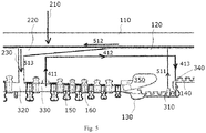
- the steam turbine comprises an outer casing 110 and an inner casing 120, and a rotor 130 having a thrust balancing piston 140, the rotor 130 being rotatably mounted inside the inner casing 120.
- a flow channel for a medium e.g., steam
- the flow channel is alternately arranged with impeller blades 150 fitted with the rotor 130 and guide blades 160 fitted with the inner casing 120, forming multiple stages of blade groups.
- the inner casing 120 and the outer casing 110 are provided with a live stream feed channel (not shown) via which the live steam is admitted into the inlet steam chamber 350 where the live steam enters the flow channel and circulates downstream around respective blade stage; with expansion and cooling of the live steam, heat energy is released to drive the rotor 130 to rotate.
- a live stream feed channel (not shown) via which the live steam is admitted into the inlet steam chamber 350 where the live steam enters the flow channel and circulates downstream around respective blade stage; with expansion and cooling of the live steam, heat energy is released to drive the rotor 130 to rotate.
- the steam is enabled to flow into a thrust balancing piston chamber 340 between the thrust balancing piston 140 and the inner casing 120 from the steam throughflow 330 when coursing through the flow channel, generating a counter force reacting against a rotor thrust, thereby achieving thrust balance and cooling the thrust balancing piston 140.
- the steam (e.g., a small portion of leakage steam from the live steam) is admissible into a steam supplementing chamber 220 between the inner casing 120 and the outer casing 110 from a sealed chamber 310 between the rotor 130 and the inner casing 120 (steam-tightness), so as to be mixed with the supplemental steam externally fed into the steam supplementing chamber 220 via the steam supplementing pipelines so as to balance, in the steam supplementing chamber 220, the throughput and pressure differentials of the supplemental steam entering the steam turbine from the two lines of steam supplementing pipelines; after the vibration excitation is eliminated, the steam is introduced into the blade staging downstream of the steam throughflow 330 via the communicating pipelines 230 evenly distributed in the circumference of the inner casing 120 to continue working, solving the vibration occurring upon opening the steam supplementing valve.
- the steam e.g., a small portion of leakage steam from the live steam
- the steam supplementing chamber 220 is arranged surrounding the outer side of the inner casing 120.
- the steam supplementing chamber 220 may be a spatial structure of any shape, which is defined by the shapes of the casing bodies of the outer casing 110 and the inner casing 120 at that position.
- the steam supplementing chamber 220 is an annular steam supplementing chamber.
- a section of the interlayer between the inner casing and the outer casing for the steam to circulate forms the steam supplementing chamber 220.
- the arrow 210 represents that one line of the steam supplementing pipelines accesses the region of the interlayer where the steam supplementing chamber 220 is located so as to feed the supplemental steam.
- the exemplary steam supplementing chamber 220 is located at the downstream segment of the interlayer, i.e., the side closer to the communicating pipe 230, wherein the closer to that side, the larger the volume of the steam supplementing chamber 220 is.
- Fig. 5 reflects that the closer the steam supplementing chamber 220 is to the communicating pipe 230, the greater the ring width of the cross section of the steam supplementing chamber 220 is. For example, by changing the structural design of the outer side of the inner casing 120, the inner diameter of the inner casing section corresponding to the position of the steam supplementing chamber 220 is diminished gradually.
- the shape/size design of the steam supplementing chamber, the location of the steam supplementing chamber in the interlayer between the inner casing and the outer casing, and the access location / supplemental steam throughput from the steam supplementing pipelines to the steam supplementing chamber may be adjusted according to actual application conditions of the steam turbine disclosed by the present disclosure; the depictions in the examples above are not limiting.
- a corresponding pipeline for the first steam channel is provided in the inner casing 120, such that the steam can start from downstream of one blade staging (referred to as the first designated blade staging) corresponding to the steam throughflow 330; the pipeline first extends perpendicular to the axial direction (schematically represented by arrow 411), and after the first turn, extends substantially parallel to the axial direction (schematically represented by the arrow 422), and then after the second turn, extends substantially perpendicular to the axial direction (schematically represented by the arrow 413), till entering the thrust balancing piston chamber 340.
- the pipeline first extends perpendicular to the axial direction (schematically represented by arrow 411), and after the first turn, extends substantially parallel to the axial direction (schematically represented by the arrow 422), and then after the second turn, extends substantially perpendicular to the axial direction (schematically represented by the arrow 413), till entering the thrust balancing piston chamber 340.
- the second steam channel includes a pipeline connecting the sealed chamber 310 to the interlayer between the inner casing and the outer casing, the interlayer between the inner casing and the outer casing, the steam supplementing chamber 220 formed in the interlayer, and a pipeline (including the communicating pipe 230) connecting the interlayer between the inner casing and the outer casing to the flow channel.
- Arrow 511 schematically represents that the steam starts from the sealed chamber 310, extending substantially perpendicular to the axial direction into the interlayer between the inner casing and the outer casing;
- Arrow 512 schematically represents that the steam extends in the upstream segment of the interlayer between the inner layer and the outer layer along the axial direction, and mixes, when coursing through the steam supplementing chamber 220 in the downstream segment, with the supplemental steam additionally fed thereinto (schematically represented by the arrow 210), and continues extending till being admitted into the communication pipe 230;
- Arrow 513 schematically represents that the steam extends substantially perpendicular to the axial direction again along the communicating pipe 230 till entering the flow channel to access the steam throughflow 320 downstream of another blade staging (referred to the second designated blade staging).
- the second designated blade staging disposed downstream of the first designated blade staging refers to one blade stage downstream of the first designated blade staging.
- the first designated blade staging corresponds to the fourth blade stage in the flow channel
- the second designated blade staging corresponds to the fifth blade stage in the flow channel.
- the present disclosure is not limited to structural adjustment based on the actual application scenarios of the steam turbine, such as changing the shape/size/turn/throughput of respective pipelines for the first and second steam channels, changing respective blade stage corresponding to the first and second designated blade staging, adjusting the number of blade stages between the first and second designated blade staging, or adjusting the feed port (corresponding to where the steam throughflow 300 is located) of the first steam channel to downstream of the output port (corresponding to where the steam throughflow 320 is located) of the second steam channel, etc.
- the steam turbine having a steam supplementing structure and the operating method therefor changes the steam flow direction in the cooling structure; besides, an appropriate annular steam supplementing chamber is provided between the inner casing and the outer casing, such that the steam may be mixed between the inner casing and the outer casing, which eliminates the throughput and pressure differentials when two lines of supplemental steam are inputted, thereby effectively overcoming the vibration upon opening of the steam supplementing valve when the steam turbine is operating.
Landscapes
- Engineering & Computer Science (AREA)
- Mechanical Engineering (AREA)
- General Engineering & Computer Science (AREA)
- Turbine Rotor Nozzle Sealing (AREA)
- Control Of Turbines (AREA)
Applications Claiming Priority (2)
| Application Number | Priority Date | Filing Date | Title |
|---|---|---|---|
| CN201811313093.8A CN109184823B (zh) | 2018-11-06 | 2018-11-06 | 一种具有补汽结构的汽轮机及其运行方法 |
| PCT/CN2019/081015 WO2020093648A1 (fr) | 2018-11-06 | 2019-04-02 | Turbine à vapeur dotée d'une structure d'ajout de vapeur et son procédé de fonctionnement |
Publications (3)
| Publication Number | Publication Date |
|---|---|
| EP3879077A1 true EP3879077A1 (fr) | 2021-09-15 |
| EP3879077A4 EP3879077A4 (fr) | 2022-08-31 |
| EP3879077B1 EP3879077B1 (fr) | 2024-08-14 |
Family
ID=64942150
Family Applications (1)
| Application Number | Title | Priority Date | Filing Date |
|---|---|---|---|
| EP19881794.2A Active EP3879077B1 (fr) | 2018-11-06 | 2019-04-02 | Turbine à vapeur dotée d'une structure d'ajout de vapeur et son procédé de fonctionnement |
Country Status (4)
| Country | Link |
|---|---|
| US (1) | US11572802B2 (fr) |
| EP (1) | EP3879077B1 (fr) |
| CN (1) | CN109184823B (fr) |
| WO (1) | WO2020093648A1 (fr) |
Cited By (1)
| Publication number | Priority date | Publication date | Assignee | Title |
|---|---|---|---|---|
| CN115234317A (zh) * | 2022-07-20 | 2022-10-25 | 上海电气电站设备有限公司 | 一种三层壳汽轮机进汽结构及汽轮机 |
Families Citing this family (8)
| Publication number | Priority date | Publication date | Assignee | Title |
|---|---|---|---|---|
| CN109184823B (zh) * | 2018-11-06 | 2024-03-19 | 上海电气电站设备有限公司 | 一种具有补汽结构的汽轮机及其运行方法 |
| CN109736905A (zh) * | 2019-03-21 | 2019-05-10 | 上海电气电站设备有限公司 | 汽轮机多级汽缸间联合冷却系统 |
| CN112127955B (zh) * | 2020-10-22 | 2025-02-11 | 中国船舶重工集团公司第七0四研究所 | 内置汽封管路及汽封压力调整器的汽缸结构 |
| CN112282870A (zh) * | 2020-11-23 | 2021-01-29 | 哈尔滨汽轮机厂有限责任公司 | 一种带有分段推力平衡系统的高压内缸 |
| CN113047911B (zh) * | 2021-03-10 | 2022-01-14 | 东方电气集团东方汽轮机有限公司 | 一种推力平衡结构 |
| CN113685236B (zh) * | 2021-08-23 | 2022-10-14 | 华能铜川照金煤电有限公司 | 一种用于单缸、单列复速级背压汽轮机的平衡活塞装置 |
| CN114508393B (zh) * | 2021-12-27 | 2023-07-18 | 东方电气集团东方汽轮机有限公司 | 甩负荷时轴向推力为零的汽缸、一次及二次再热汽轮机 |
| CN116201610B (zh) * | 2023-03-10 | 2026-04-21 | 上海电气电站设备有限公司 | 一种降低漏汽量的分段式过桥汽封、方法、及汽轮机 |
Family Cites Families (12)
| Publication number | Priority date | Publication date | Assignee | Title |
|---|---|---|---|---|
| US2823891A (en) * | 1953-05-20 | 1958-02-18 | Westinghouse Electric Corp | Steam turbine |
| US2796231A (en) * | 1954-03-24 | 1957-06-18 | Westinghouse Electric Corp | High pressure steam turbine casing structure |
| US2905434A (en) * | 1954-07-08 | 1959-09-22 | Westinghouse Electric Corp | Turbine apparatus |
| US3614255A (en) * | 1969-11-13 | 1971-10-19 | Gen Electric | Thrust balancing arrangement for steam turbine |
| EP1624155A1 (fr) * | 2004-08-02 | 2006-02-08 | Siemens Aktiengesellschaft | Turbine à vapeur et procédé d'opération d'une turbine à vapeur |
| CN100378296C (zh) * | 2006-07-19 | 2008-04-02 | 上海汽轮机有限公司 | 一种汽轮机高压内缸冷却方法 |
| EP2192266A1 (fr) * | 2008-11-26 | 2010-06-02 | Siemens Aktiengesellschaft | Dispositif de rotor pour une turbine à vapeur et turbine à vapeur |
| EP2412937A1 (fr) * | 2010-07-30 | 2012-02-01 | Siemens Aktiengesellschaft | Turbine à vapeur et procédé de refroidissement de celle-ci |
| CN103422916B (zh) * | 2013-08-30 | 2015-09-30 | 上海电气电站设备有限公司 | 汽轮机的抽、补汽通道结构 |
| CN209494598U (zh) * | 2018-11-06 | 2019-10-15 | 上海电气电站设备有限公司 | 一种具有补汽结构的汽轮机 |
| CN109162772B (zh) * | 2018-11-06 | 2024-03-19 | 上海电气电站设备有限公司 | 一种汽轮机及其内冷却方法 |
| CN109184823B (zh) | 2018-11-06 | 2024-03-19 | 上海电气电站设备有限公司 | 一种具有补汽结构的汽轮机及其运行方法 |
-
2018
- 2018-11-06 CN CN201811313093.8A patent/CN109184823B/zh active Active
-
2019
- 2019-04-02 WO PCT/CN2019/081015 patent/WO2020093648A1/fr not_active Ceased
- 2019-04-02 US US17/288,391 patent/US11572802B2/en active Active
- 2019-04-02 EP EP19881794.2A patent/EP3879077B1/fr active Active
Cited By (1)
| Publication number | Priority date | Publication date | Assignee | Title |
|---|---|---|---|---|
| CN115234317A (zh) * | 2022-07-20 | 2022-10-25 | 上海电气电站设备有限公司 | 一种三层壳汽轮机进汽结构及汽轮机 |
Also Published As
| Publication number | Publication date |
|---|---|
| WO2020093648A1 (fr) | 2020-05-14 |
| EP3879077A4 (fr) | 2022-08-31 |
| CN109184823A (zh) | 2019-01-11 |
| US11572802B2 (en) | 2023-02-07 |
| EP3879077B1 (fr) | 2024-08-14 |
| US20210381395A1 (en) | 2021-12-09 |
| CN109184823B (zh) | 2024-03-19 |
Similar Documents
| Publication | Publication Date | Title |
|---|---|---|
| US11572802B2 (en) | Steam turbine having a steam supplementing structure and operating method therefor | |
| US8858158B2 (en) | Steam turbine and steam turbine plant system | |
| CN100575671C (zh) | 汽轮机和汽轮机运行方法 | |
| CN102128054A (zh) | 汽轮机 | |
| JP5692966B2 (ja) | 蒸気タービン内部の回転部品を冷却するための方法及び装置 | |
| JP6479386B2 (ja) | 蒸気タービン | |
| EP3879078B1 (fr) | Turbine à vapeur et son procédé de refroidissement interne | |
| JP6639514B2 (ja) | 軸流タービン | |
| EP2596215B1 (fr) | Ensemble d'étanchéité permettant de commander un écoulement de fluide | |
| CN209494598U (zh) | 一种具有补汽结构的汽轮机 | |
| CN106574502B (zh) | 蒸汽轮机和用于运行蒸汽轮机的方法 | |
| EP3296514B1 (fr) | Spirale d'entrée de turbine à vapeur à commande fluidique | |
| KR20180073249A (ko) | 가스터빈 | |
| CN103052768B (zh) | 蒸汽轮机以及用于冷却这种蒸汽轮机的方法 | |
| JP2015158190A (ja) | 蒸気タービンシステム | |
| JP6637064B2 (ja) | 軸流タービン | |
| KR102087054B1 (ko) | 다단 배치되는 터빈 일체형 회전자가 구비된 발전기 및 이를 포함하는 발전 사이클 시스템 | |
| US20130323009A1 (en) | Methods and apparatus for cooling rotary components within a steam turbine | |
| CN107002494B (zh) | 涡轮轴的可控冷却 | |
| EP3205817A1 (fr) | Rotor refroidi par fluide pour une turbine à gaz | |
| KR102077731B1 (ko) | 터빈 일체형 회전자가 구비되는 발전기 및 이를 포함하는 발전 사이클 시스템 |
Legal Events
| Date | Code | Title | Description |
|---|---|---|---|
| STAA | Information on the status of an ep patent application or granted ep patent |
Free format text: STATUS: THE INTERNATIONAL PUBLICATION HAS BEEN MADE |
|
| PUAI | Public reference made under article 153(3) epc to a published international application that has entered the european phase |
Free format text: ORIGINAL CODE: 0009012 |
|
| STAA | Information on the status of an ep patent application or granted ep patent |
Free format text: STATUS: REQUEST FOR EXAMINATION WAS MADE |
|
| 17P | Request for examination filed |
Effective date: 20210426 |
|
| AK | Designated contracting states |
Kind code of ref document: A1 Designated state(s): AL AT BE BG CH CY CZ DE DK EE ES FI FR GB GR HR HU IE IS IT LI LT LU LV MC MK MT NL NO PL PT RO RS SE SI SK SM TR |
|
| DAV | Request for validation of the european patent (deleted) | ||
| DAX | Request for extension of the european patent (deleted) | ||
| A4 | Supplementary search report drawn up and despatched |
Effective date: 20220729 |
|
| RIC1 | Information provided on ipc code assigned before grant |
Ipc: F01D 3/04 20060101ALI20220725BHEP Ipc: F01D 25/26 20060101ALI20220725BHEP Ipc: F01D 25/14 20060101ALI20220725BHEP Ipc: F01D 25/12 20060101AFI20220725BHEP |
|
| REG | Reference to a national code |
Ref country code: DE Ref legal event code: R079 Free format text: PREVIOUS MAIN CLASS: F01D0025120000 Ipc: F01D0025040000 Ref country code: DE Ref legal event code: R079 Ref document number: 602019057155 Country of ref document: DE Free format text: PREVIOUS MAIN CLASS: F01D0025120000 Ipc: F01D0025040000 |
|
| RIC1 | Information provided on ipc code assigned before grant |
Ipc: F01D 3/04 20060101ALI20240304BHEP Ipc: F01D 25/26 20060101ALI20240304BHEP Ipc: F01D 25/14 20060101ALI20240304BHEP Ipc: F01D 25/12 20060101ALI20240304BHEP Ipc: F01D 25/04 20060101AFI20240304BHEP |
|
| GRAP | Despatch of communication of intention to grant a patent |
Free format text: ORIGINAL CODE: EPIDOSNIGR1 |
|
| STAA | Information on the status of an ep patent application or granted ep patent |
Free format text: STATUS: GRANT OF PATENT IS INTENDED |
|
| INTG | Intention to grant announced |
Effective date: 20240415 |
|
| GRAS | Grant fee paid |
Free format text: ORIGINAL CODE: EPIDOSNIGR3 |
|
| GRAA | (expected) grant |
Free format text: ORIGINAL CODE: 0009210 |
|
| STAA | Information on the status of an ep patent application or granted ep patent |
Free format text: STATUS: THE PATENT HAS BEEN GRANTED |
|
| AK | Designated contracting states |
Kind code of ref document: B1 Designated state(s): AL AT BE BG CH CY CZ DE DK EE ES FI FR GB GR HR HU IE IS IT LI LT LU LV MC MK MT NL NO PL PT RO RS SE SI SK SM TR |
|
| REG | Reference to a national code |
Ref country code: GB Ref legal event code: FG4D |
|
| REG | Reference to a national code |
Ref country code: CH Ref legal event code: EP |
|
| REG | Reference to a national code |
Ref country code: DE Ref legal event code: R096 Ref document number: 602019057155 Country of ref document: DE |
|
| REG | Reference to a national code |
Ref country code: IE Ref legal event code: FG4D |
|
| REG | Reference to a national code |
Ref country code: LT Ref legal event code: MG9D |
|
| REG | Reference to a national code |
Ref country code: NL Ref legal event code: MP Effective date: 20240814 |
|
| PG25 | Lapsed in a contracting state [announced via postgrant information from national office to epo] |
Ref country code: NO Free format text: LAPSE BECAUSE OF FAILURE TO SUBMIT A TRANSLATION OF THE DESCRIPTION OR TO PAY THE FEE WITHIN THE PRESCRIBED TIME-LIMIT Effective date: 20241114 |
|
| REG | Reference to a national code |
Ref country code: AT Ref legal event code: MK05 Ref document number: 1713478 Country of ref document: AT Kind code of ref document: T Effective date: 20240814 |
|
| PG25 | Lapsed in a contracting state [announced via postgrant information from national office to epo] |
Ref country code: FI Free format text: LAPSE BECAUSE OF FAILURE TO SUBMIT A TRANSLATION OF THE DESCRIPTION OR TO PAY THE FEE WITHIN THE PRESCRIBED TIME-LIMIT Effective date: 20240814 Ref country code: NL Free format text: LAPSE BECAUSE OF FAILURE TO SUBMIT A TRANSLATION OF THE DESCRIPTION OR TO PAY THE FEE WITHIN THE PRESCRIBED TIME-LIMIT Effective date: 20240814 Ref country code: GR Free format text: LAPSE BECAUSE OF FAILURE TO SUBMIT A TRANSLATION OF THE DESCRIPTION OR TO PAY THE FEE WITHIN THE PRESCRIBED TIME-LIMIT Effective date: 20241115 Ref country code: PT Free format text: LAPSE BECAUSE OF FAILURE TO SUBMIT A TRANSLATION OF THE DESCRIPTION OR TO PAY THE FEE WITHIN THE PRESCRIBED TIME-LIMIT Effective date: 20241216 Ref country code: PL Free format text: LAPSE BECAUSE OF FAILURE TO SUBMIT A TRANSLATION OF THE DESCRIPTION OR TO PAY THE FEE WITHIN THE PRESCRIBED TIME-LIMIT Effective date: 20240814 |
|
| PG25 | Lapsed in a contracting state [announced via postgrant information from national office to epo] |
Ref country code: BG Free format text: LAPSE BECAUSE OF FAILURE TO SUBMIT A TRANSLATION OF THE DESCRIPTION OR TO PAY THE FEE WITHIN THE PRESCRIBED TIME-LIMIT Effective date: 20240814 |
|
| PG25 | Lapsed in a contracting state [announced via postgrant information from national office to epo] |
Ref country code: LV Free format text: LAPSE BECAUSE OF FAILURE TO SUBMIT A TRANSLATION OF THE DESCRIPTION OR TO PAY THE FEE WITHIN THE PRESCRIBED TIME-LIMIT Effective date: 20240814 |
|
| PG25 | Lapsed in a contracting state [announced via postgrant information from national office to epo] |
Ref country code: IS Free format text: LAPSE BECAUSE OF FAILURE TO SUBMIT A TRANSLATION OF THE DESCRIPTION OR TO PAY THE FEE WITHIN THE PRESCRIBED TIME-LIMIT Effective date: 20241214 Ref country code: AT Free format text: LAPSE BECAUSE OF FAILURE TO SUBMIT A TRANSLATION OF THE DESCRIPTION OR TO PAY THE FEE WITHIN THE PRESCRIBED TIME-LIMIT Effective date: 20240814 |
|
| PG25 | Lapsed in a contracting state [announced via postgrant information from national office to epo] |
Ref country code: HR Free format text: LAPSE BECAUSE OF FAILURE TO SUBMIT A TRANSLATION OF THE DESCRIPTION OR TO PAY THE FEE WITHIN THE PRESCRIBED TIME-LIMIT Effective date: 20240814 |
|
| PG25 | Lapsed in a contracting state [announced via postgrant information from national office to epo] |
Ref country code: RS Free format text: LAPSE BECAUSE OF FAILURE TO SUBMIT A TRANSLATION OF THE DESCRIPTION OR TO PAY THE FEE WITHIN THE PRESCRIBED TIME-LIMIT Effective date: 20241114 Ref country code: ES Free format text: LAPSE BECAUSE OF FAILURE TO SUBMIT A TRANSLATION OF THE DESCRIPTION OR TO PAY THE FEE WITHIN THE PRESCRIBED TIME-LIMIT Effective date: 20240814 |
|
| PG25 | Lapsed in a contracting state [announced via postgrant information from national office to epo] |
Ref country code: RS Free format text: LAPSE BECAUSE OF FAILURE TO SUBMIT A TRANSLATION OF THE DESCRIPTION OR TO PAY THE FEE WITHIN THE PRESCRIBED TIME-LIMIT Effective date: 20241114 Ref country code: PT Free format text: LAPSE BECAUSE OF FAILURE TO SUBMIT A TRANSLATION OF THE DESCRIPTION OR TO PAY THE FEE WITHIN THE PRESCRIBED TIME-LIMIT Effective date: 20241216 Ref country code: PL Free format text: LAPSE BECAUSE OF FAILURE TO SUBMIT A TRANSLATION OF THE DESCRIPTION OR TO PAY THE FEE WITHIN THE PRESCRIBED TIME-LIMIT Effective date: 20240814 Ref country code: NO Free format text: LAPSE BECAUSE OF FAILURE TO SUBMIT A TRANSLATION OF THE DESCRIPTION OR TO PAY THE FEE WITHIN THE PRESCRIBED TIME-LIMIT Effective date: 20241114 Ref country code: NL Free format text: LAPSE BECAUSE OF FAILURE TO SUBMIT A TRANSLATION OF THE DESCRIPTION OR TO PAY THE FEE WITHIN THE PRESCRIBED TIME-LIMIT Effective date: 20240814 Ref country code: LV Free format text: LAPSE BECAUSE OF FAILURE TO SUBMIT A TRANSLATION OF THE DESCRIPTION OR TO PAY THE FEE WITHIN THE PRESCRIBED TIME-LIMIT Effective date: 20240814 Ref country code: IS Free format text: LAPSE BECAUSE OF FAILURE TO SUBMIT A TRANSLATION OF THE DESCRIPTION OR TO PAY THE FEE WITHIN THE PRESCRIBED TIME-LIMIT Effective date: 20241214 Ref country code: HR Free format text: LAPSE BECAUSE OF FAILURE TO SUBMIT A TRANSLATION OF THE DESCRIPTION OR TO PAY THE FEE WITHIN THE PRESCRIBED TIME-LIMIT Effective date: 20240814 Ref country code: GR Free format text: LAPSE BECAUSE OF FAILURE TO SUBMIT A TRANSLATION OF THE DESCRIPTION OR TO PAY THE FEE WITHIN THE PRESCRIBED TIME-LIMIT Effective date: 20241115 Ref country code: FI Free format text: LAPSE BECAUSE OF FAILURE TO SUBMIT A TRANSLATION OF THE DESCRIPTION OR TO PAY THE FEE WITHIN THE PRESCRIBED TIME-LIMIT Effective date: 20240814 Ref country code: ES Free format text: LAPSE BECAUSE OF FAILURE TO SUBMIT A TRANSLATION OF THE DESCRIPTION OR TO PAY THE FEE WITHIN THE PRESCRIBED TIME-LIMIT Effective date: 20240814 Ref country code: BG Free format text: LAPSE BECAUSE OF FAILURE TO SUBMIT A TRANSLATION OF THE DESCRIPTION OR TO PAY THE FEE WITHIN THE PRESCRIBED TIME-LIMIT Effective date: 20240814 Ref country code: AT Free format text: LAPSE BECAUSE OF FAILURE TO SUBMIT A TRANSLATION OF THE DESCRIPTION OR TO PAY THE FEE WITHIN THE PRESCRIBED TIME-LIMIT Effective date: 20240814 |
|
| PG25 | Lapsed in a contracting state [announced via postgrant information from national office to epo] |
Ref country code: DK Free format text: LAPSE BECAUSE OF FAILURE TO SUBMIT A TRANSLATION OF THE DESCRIPTION OR TO PAY THE FEE WITHIN THE PRESCRIBED TIME-LIMIT Effective date: 20240814 Ref country code: RO Free format text: LAPSE BECAUSE OF FAILURE TO SUBMIT A TRANSLATION OF THE DESCRIPTION OR TO PAY THE FEE WITHIN THE PRESCRIBED TIME-LIMIT Effective date: 20240814 Ref country code: SM Free format text: LAPSE BECAUSE OF FAILURE TO SUBMIT A TRANSLATION OF THE DESCRIPTION OR TO PAY THE FEE WITHIN THE PRESCRIBED TIME-LIMIT Effective date: 20240814 |
|
| PG25 | Lapsed in a contracting state [announced via postgrant information from national office to epo] |
Ref country code: EE Free format text: LAPSE BECAUSE OF FAILURE TO SUBMIT A TRANSLATION OF THE DESCRIPTION OR TO PAY THE FEE WITHIN THE PRESCRIBED TIME-LIMIT Effective date: 20240814 |
|
| PG25 | Lapsed in a contracting state [announced via postgrant information from national office to epo] |
Ref country code: CZ Free format text: LAPSE BECAUSE OF FAILURE TO SUBMIT A TRANSLATION OF THE DESCRIPTION OR TO PAY THE FEE WITHIN THE PRESCRIBED TIME-LIMIT Effective date: 20240814 |
|
| PG25 | Lapsed in a contracting state [announced via postgrant information from national office to epo] |
Ref country code: SK Free format text: LAPSE BECAUSE OF FAILURE TO SUBMIT A TRANSLATION OF THE DESCRIPTION OR TO PAY THE FEE WITHIN THE PRESCRIBED TIME-LIMIT Effective date: 20240814 |
|
| REG | Reference to a national code |
Ref country code: DE Ref legal event code: R097 Ref document number: 602019057155 Country of ref document: DE |
|
| PLBE | No opposition filed within time limit |
Free format text: ORIGINAL CODE: 0009261 |
|
| STAA | Information on the status of an ep patent application or granted ep patent |
Free format text: STATUS: NO OPPOSITION FILED WITHIN TIME LIMIT |
|
| PGFP | Annual fee paid to national office [announced via postgrant information from national office to epo] |
Ref country code: DE Payment date: 20250530 Year of fee payment: 7 |
|
| PGFP | Annual fee paid to national office [announced via postgrant information from national office to epo] |
Ref country code: IT Payment date: 20250429 Year of fee payment: 7 |
|
| PGFP | Annual fee paid to national office [announced via postgrant information from national office to epo] |
Ref country code: FR Payment date: 20250427 Year of fee payment: 7 |
|
| 26N | No opposition filed |
Effective date: 20250515 |
|
| PG25 | Lapsed in a contracting state [announced via postgrant information from national office to epo] |
Ref country code: SE Free format text: LAPSE BECAUSE OF FAILURE TO SUBMIT A TRANSLATION OF THE DESCRIPTION OR TO PAY THE FEE WITHIN THE PRESCRIBED TIME-LIMIT Effective date: 20240814 |
|
| REG | Reference to a national code |
Ref country code: CH Ref legal event code: H13 Free format text: ST27 STATUS EVENT CODE: U-0-0-H10-H13 (AS PROVIDED BY THE NATIONAL OFFICE) Effective date: 20251125 |
|
| PG25 | Lapsed in a contracting state [announced via postgrant information from national office to epo] |
Ref country code: LU Free format text: LAPSE BECAUSE OF NON-PAYMENT OF DUE FEES Effective date: 20250402 |
|
| PG25 | Lapsed in a contracting state [announced via postgrant information from national office to epo] |
Ref country code: MC Free format text: LAPSE BECAUSE OF FAILURE TO SUBMIT A TRANSLATION OF THE DESCRIPTION OR TO PAY THE FEE WITHIN THE PRESCRIBED TIME-LIMIT Effective date: 20240814 |
|
| GBPC | Gb: european patent ceased through non-payment of renewal fee |
Effective date: 20250402 |
|
| REG | Reference to a national code |
Ref country code: BE Ref legal event code: MM Effective date: 20250430 |
|
| PG25 | Lapsed in a contracting state [announced via postgrant information from national office to epo] |
Ref country code: GB Free format text: LAPSE BECAUSE OF NON-PAYMENT OF DUE FEES Effective date: 20250402 |
|
| PG25 | Lapsed in a contracting state [announced via postgrant information from national office to epo] |
Ref country code: BE Free format text: LAPSE BECAUSE OF NON-PAYMENT OF DUE FEES Effective date: 20250430 |
|
| PG25 | Lapsed in a contracting state [announced via postgrant information from national office to epo] |
Ref country code: CH Free format text: LAPSE BECAUSE OF NON-PAYMENT OF DUE FEES Effective date: 20250430 |
|
| PG25 | Lapsed in a contracting state [announced via postgrant information from national office to epo] |
Ref country code: IE Free format text: LAPSE BECAUSE OF NON-PAYMENT OF DUE FEES Effective date: 20250402 |