EP3879103B1 - Diaphragme à volume élevé doté d'un renforcement géométriquement amélioré - Google Patents
Diaphragme à volume élevé doté d'un renforcement géométriquement amélioré Download PDFInfo
- Publication number
- EP3879103B1 EP3879103B1 EP21161205.6A EP21161205A EP3879103B1 EP 3879103 B1 EP3879103 B1 EP 3879103B1 EP 21161205 A EP21161205 A EP 21161205A EP 3879103 B1 EP3879103 B1 EP 3879103B1
- Authority
- EP
- European Patent Office
- Prior art keywords
- wall
- support section
- diaphragm
- exterior
- volume large
- Prior art date
- Legal status (The legal status is an assumption and is not a legal conclusion. Google has not performed a legal analysis and makes no representation as to the accuracy of the status listed.)
- Active
Links
Images



Classifications
-
- F—MECHANICAL ENGINEERING; LIGHTING; HEATING; WEAPONS; BLASTING
- F04—POSITIVE - DISPLACEMENT MACHINES FOR LIQUIDS; PUMPS FOR LIQUIDS OR ELASTIC FLUIDS
- F04B—POSITIVE-DISPLACEMENT MACHINES FOR LIQUIDS; PUMPS
- F04B43/00—Machines, pumps, or pumping installations having flexible working members
- F04B43/0009—Special features
- F04B43/0054—Special features particularities of the flexible members
- F04B43/0063—Special features particularities of the flexible members bell-shaped flexible members
-
- F—MECHANICAL ENGINEERING; LIGHTING; HEATING; WEAPONS; BLASTING
- F04—POSITIVE - DISPLACEMENT MACHINES FOR LIQUIDS; PUMPS FOR LIQUIDS OR ELASTIC FLUIDS
- F04B—POSITIVE-DISPLACEMENT MACHINES FOR LIQUIDS; PUMPS
- F04B43/00—Machines, pumps, or pumping installations having flexible working members
- F04B43/02—Machines, pumps, or pumping installations having flexible working members having plate-like flexible members, e.g. diaphragms
Definitions
- This invention relates generally to diaphragm pumps, and, more particularly, to a high-volume large diaphragm of unitary construction that is comprised of geometrically enhanced reinforcement support sections.
- Diaphragm pumps are useful for transferring large volumes of fluids (e.g., liquid and gases) for many industries, including but not limited to agricultural, construction and marine industries. Such pumps are commonly utilized for displacing water and may even transfer highly viscous, mud-laden water.
- fluids e.g., liquid and gases
- Such pumps are commonly utilized for displacing water and may even transfer highly viscous, mud-laden water.
- high-volume large diaphragms, particularly diaphragms with relatively high walls risk premature failure as a result of augmented effects from distress mechanisms commonly encountered by diaphragms used in diaphragm pumps.
- a high-volume large diaphragm for use with a diaphragm pump must be capable of operating without failure for a considerable period of time.
- the high-volume large diaphragm should be capable of operating at least 600 hours and ideally at least 1200 hours. It is well known that improperly reinforced high-volume large diaphragms tend to fail after less than 600 hours of use.
- US 10 030 642B1 discloses a reinforced high-volume elastomeric pump diaphragm featuring several concentric circumferential reinforcing ribs (areas of increased thickness) integrally formed in the angled wall. Two ribs extend from the exterior to the interior. One rib, nearest the rim of the diaphragm, extends only to the exterior. This particular arrangement of ribs reduces rolling and appreciably improves performance by prolonging the useful life of the diaphragm.
- the high-volume large diaphragm be comprised of geometrically enhanced reinforcement to optimally withstand the distress mechanisms encountered during operation. With such geometrically enhanced reinforcement, the high-volume large diaphragm can be in use for at least 1,200 hours.
- the invention is intended to solve one or more of the issues noted above.
- a high-volume large diaphragm with geometrically enhanced reinforcement is provided.
- a high-volume large diaphragm is hat shaped in an undisturbed state.
- the vertical height of the wall (e.g. the wall height) of the high-volume large diaphragm, measured from the bottom surface of the diaphragm cap to the top surface of the diaphragm rim, is at least three inches.
- the wall of a high-volume large diaphragm has a maximum diameter of at least three times the wall height and a minimum diameter of at least twice the wall height.
- the design of the high-volume large diaphragm's wall is of importance to its functionality and its durability.
- the actuation of the high-volume large diaphragm results in periodic alternating stresses within the diaphragm wall.
- a diaphragm pump uses an eccentrically driven pushrod is used to actuate a high-volume large diaphragm the elliptical trajectory of the pushrod amplifies the magnitude of alternating stresses.
- the stresses imparted on the diaphragm wall are optimally resisted by a wall that have areas of increased thickness, hereinafter referred to as support sections.
- support sections are too thick or too closely spaced the diaphragm wall will be over-reinforced resulting in excessive stress concentrations that develop at the interface of the wall surfaces and support sections. Cracks will often form adjacent to the support sections when the diaphragm wall is over-reinforced as a result of excessive stress concentrations. Failure of the high-volume large diaphragm often occur at or near locations where cracks within the wall have previously formed.
- the wall of a high-volume large diaphragm is also subjected to wear from abrasion. Abrasion of the interior wall surfaces can also induce stress amplifications as a result of acute decreased cross-sectional thickness of the diaphragm wall.
- the diverse applications that the high-volume large diaphragm is equipped to handle can often increase the exposure of the interior wall surfaces to sharp or jagged debris that could abrade or even penetrate the diaphragm wall. Alternating stresses and abrasion are distress mechanisms that impact the wall of a high-volume large diaphragm and in turn the useful service life of the high-volume large diaphragm.
- Improvements for a high-volume large diaphragm are comprised of a collection of one or more pairs of continuous, circumferential support sections located on an angled wall. At least one pair of vertically offset exterior and interior circumferential support sections are provided on the wall. Each support section is comprised of a smoothly curved solid projection that protrudes from only one surface of the wall. The support sections are vertically offset from each other such that an exterior support section and an interior support section are not located at the same elevation along the wall.
- An anticipated embodiment of a high-volume large pump diaphragm has a pumping volume in excess of 250 cubic inches.
- the high-volume large diaphragm features a hat shaped structure, which includes a wall having a moderately thin-walled surface shaped as a hollow frustum.
- the wall defines a first end with a first diameter and a second end opposite the first end and having a second diameter. The second diameter is greater than the first diameter.
- the wall includes an exterior surface and an interior surface.
- a rim is formed at the second end. The rim is formed as a circular flange extending outwardly from the wall.
- a disk-shaped cap is formed across the first end and a plurality of openings are provided within the cap.
- An exterior support section is located closer to the rim. Importantly, the exterior support section extends only to the exterior. Similarly, the interior support section protrudes only to the interior. A pair of vertically offset support sections, as described above, reduces rolling of the diaphragm wall during compression while also reducing stress concentrations within the wall at the support sections.
- a non-limiting embodiment of a high-volume large diaphragm has a pumping volume of at least 250 cubic inches.
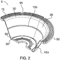
- the high-volume large diaphragm features a hat shaped structure, which includes a wall 20 having a moderately thin-walled surface shaped as a hollow frustum.
- the wall 20 defines a first end with a first diameter and a second end opposite the first end and having a second diameter. The second diameter is greater than the first diameter.
- the wall 20 has an exterior surface and an interior surface. The vertical distance between the first end of the wall to the second end of the wall (i.e. the wall height) is at least three inches.
- the wall 20 includes structural features at the first end and the second end.
- a rim 50 is formed at the second end of the wall 20 .
- the rim 50 is comprised of a circular flange extending outwardly from the wall.
- a cap 60 is formed across the first end of the wall 20 .
- the cap 60 includes a plurality of openings 80 , 81 .
- the rim 50 and the cap 60 each include an upper surface and a lower surface.
- a plurality of concentric rim ridges 15 are formed on the upper surface and the lower surface of the rim 50 .
- a plurality of concentric cap ridges 90 are formed on the upper surface and lower surface of the cap 60 .
- the wall 20 includes a pair of support sections 10 .
- Each support section of the pair of support section 10 is comprised of a solid projection.
- Each support section of the pair of support sections is circumferentially continuous around the diaphragm wall.
- An exterior support section 10a is furthest from the rim 50 and protrudes only from the exterior surface of the wall 20 and not from the interior surface of the wall 20 .
- An interior support section 10b is closest to the rim 50 and protrudes only from the interior surface of the wall 20 and not from the exterior surface of the wall 20 .
- an alternative support section configuration is anticipated to provide the exterior support section 10a closest to the rim 50 and the interior support section 10b is provided furthest from the rim 50 .
- the high-volume large diaphragm comprises relative dimensions defining certain structural features.
- the thickness of the wall 20 of the high-volume large diaphragm is preferably about 0.170 inches to 0.150 inches, and a pair of support sections 10 that protrude from the wall 20 a distance not greater than one times the wall 20 thickness.
- Each of the circumferential support sections 10a , 10b has a smoothly curved cross section shape comprised of a series of reverse curves.
- the exterior support section 10a is further from the rim 50 relative to the interior support section 10b and protrudes only from the exterior surface of the wall 20 and not from the interior surface of the wall 20 .
- the interior support section 10b is closer to the rim 50 relative to the exterior support section 10a and protrudes only from the interior surface of the wall 20 and not from the exterior surface of the wall 20 .
- the interior support section 10b is located approximately at mid height of the wall 20 .
- Each support section 10a, 10b respectively protrudes from the exterior and interior of the wall 20 a distance not greater than one times the wall thickness.
- the exterior support section 10a is located approximately mid height between the cap 60 and the interior support section 10b .
- the high-volume diaphragm 5 is generally hat shaped, with a rim 50 at the nominal bottom, a cap 60 at the nominal top, and a wall 20 protruding from the rim 50 to the cap 60 .
- a first filleted edge 30 provides a transition from the cap 60 to the top portion of the wall 20 and a second filleted edge provides a transition from the rim 50 to the bottom portion of the wall 20.
- the wall 20 has the shape of a hollow frustum.
- the angle of the wall 20 is a draft angle for molding.
- the diaphragm 5 is formed via an injection molding process that provides unitary construction of the diaphragm 5 , it may also be integrally formed.
- the diaphragm 5 features a pair of vertically offset support sections 10 , comprising an exterior support section 10a in the angled wall 20 and an interior support section 10b in the angled wall 20 .
- the top of the high-volume large diaphragm 5 or component thereof as shown in Figure 2 is referred to as the nominal top, and, likewise, the bottom of the diaphragm or component thereof as shown in Figure 2 is referred to as the nominal bottom.
- the support sections 10a, 10b are comprised of continuous circumferential areas of increased thickness along the wall 20 that smoothly transition from the wall 20 using a series of reverse curves. It is well known that a reverse curve is defined by a reversal of the concavity of the curve.
- the series of reverse curves are comprised of three reverse curves of which the upper and lower reverse curves have equal radii that are smaller relative to the radius of the middle curve.
- the detail view in Figure 3 provides further illustrative reference to this dimensional relationship.
- the exterior of the diaphragm 5 is illustrated in Figure 2 and 3 .
- the interior of the diaphragm is shown in Figures 1 , 2 , and 3 .
- the cap 60 is forced towards the rim 50 , forcing fluid out of the interior space.
- the interior support section 10b is shown in Figures 1 , 2 , and 3 .
- the arrangement of support sections 10a , 10b as shown in Figures 1 through 3 reduces rolling of the diaphragm wall 20 as the pushrod 100 traverses towards the diaphragm 5 and reduces wrinkling of the wall 20 as the pushrod 100 traverses away from the diaphragm 5 .
- the reduction in mechanical strain from the pair of vertically off-set support sections 10 results in a reduction in alternating stresses.
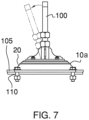
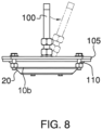
- the pushrod 100 is attached to an eccentric sheave driven by the motor of the diaphragm pump. As the pushrod 100 rotates about the eccentric sheave its inclination varies which results in an eccentric force being applied to the high-volume large diaphragm 5 .
- the eccentric force imparted on the high-volume large diaphragm 5 from the pushrod 100 creates additional stresses in the high-volume large diaphragm 5 that amplify the alternating stresses.
- the configuration of the pair of vertically offset support sections 10 optimally reinforce the walls of the high-volume large diaphragm 5 to resist these additional stresses resulting from the eccentrically driven pushrod 100 .
- the of the support sections 10a , 10b do not protrude from the wall 20 by more than one times the thickness of the wall 20 .
- the thickness of the wall 20 of the exemplary diaphragm 5 is about 0.150 inches.
- the exterior support section 10a protrudes from the exterior surface of the wall 20 up to one times the thickness of the wall 20 , preferably a maximum of about 0.5 to 0.6 times the thickness of the wall 20 .
- the interior support section 10b protrudes from the exterior surface of the wall 20 up to to one times the thickness of the wall 20 , preferably a maximum of about 0.5 to 0.6 times the thickness of the wall 20 .
- the rim 50 is a flange that extends peripherally outwardly (e.g., about 1 inch outwardly) at the base of the wall 20 .
- a plurality of concentric shallow rim ridges 15 are formed on the top surface and bottom surface of the rim 50 .
- the rim ridges 15 provide seals and improve the traction of the surfaces when the rim 50 is clamped for operation.
- a plurality of alignment cutouts 95 are provided in the free edge of the rim 50 . When installed, the rim 50 is clamped between a mounting surface and a ring plate 105 ( Fig. 7 and Fig. 8 ). Shanks of bolts 110 protrude through the ring plate 105 into the mounting surface. The alignment cutouts 95 align with the shank of each bolt 110 , such that the shank protrudes through the concavity.
- a disc-shaped cap 60 extends from the narrower end of the wall 20 .
- the interior surface of the wall 20 is visible in Figures 1 , 2 , and 3 .
- the plurality of openings 80 , 81 is provided in the cap 60 .
- Aplurality of concentric shallow cap ridges 90 are formed on the top surface and bottom surface of the cap 60 .
- the cap ridges 90 provide seals and increased traction between abutting surfaces when the cap 60 is clamped to the pushrod 100 for installation.
- This invention is not limited to use with a particular pumping mechanism. However, the invention is optimally reinforced for use with a pumping mechanism that is comprised of a pushrod 100 that is positively connected to the diaphragm 5 .
- a diaphragm 5 is comprised of a thermoplastic elastomer (TPE), and more particularly a thermoplastic vulcanizate (TPV), and even more particularly Exxon Mobile Corporation's Santoprene TM TPV.
- TPE thermoplastic elastomer
- TPV thermoplastic vulcanizate
- Santoprene TM TPV is a dynamically vulcanized alloy comprised of cured EPDM rubber particles encapsulated in a polypropylene (PP) matrix.
- PP polypropylene
- Santoprene TM TPV has been found effective for such a diaphragm 5 , providing flexibility (elasticity and resilience) and acceptable structural integrity for long-term performance.
- the diaphragm 5 is via injection molding.
- a diaphragm 6 further includes a rim 50 with a reduced plurality of alignment cutouts 95 .
- a diaphragm 7 is anticipated providing a pair of vertically offset support sections 10 and a second pair of vertically off-set ridges 12 .
- Providing more than one pair of vertically offset support sections 10 , 12 enhances durability of high-volume large diaphragms that have significantly greater wall height and prone to amplified stresses.
Landscapes
- Engineering & Computer Science (AREA)
- Mechanical Engineering (AREA)
- General Engineering & Computer Science (AREA)
- Reciprocating Pumps (AREA)
- Diaphragms For Electromechanical Transducers (AREA)
Claims (13)
- Grand diaphragme à volume élevé comprenant une structure en forme de chapeau, la structure en forme de chapeau comprenant :a. une paroi (20) ;ladite paroi (20) étant façonnée sous la forme d'un tronc creux ;ladite paroi (20) fournissant une première extrémité avec un premier diamètre et une seconde extrémité opposée à la première extrémité et possédant un second diamètre ;le second diamètre étant supérieur au premier diamètre ;la paroi (20) comprenant une surface extérieure et une surface intérieure ;b. un rebord (50) ;ledit rebord (50) étant disposé au niveau de la seconde extrémité de la paroi (20) ;ledit rebord (50) comprenant une bride circulaire s'étendant vers l'extérieur à partir de la paroi (20) ;c. un capuchon (60) ;
ledit capuchon (60) étant formé à travers la première extrémité de la paroi (20) ; etd. une paire de sections de support (10) ;ladite paire de sections de support (10) étant formée sur la paroi (20) ;la paire de sections de support (10) possédant une saillie solide qui fait saillie à partir de la paroi (20) ;la paire de sections de support (10) comprenant une section de support extérieure (10a) et une section de support intérieure (10b) ;caractérisé en ce quela section de support extérieure (10a) faisant saillie uniquement à partir de la surface extérieure de la paroi (20) et non à partir de la surface intérieure de la paroi (20) ;la section de support intérieure (10b) faisant saillie à partir de la surface intérieure de la paroi (20) et non à partir de la surface extérieure de la paroi (20) ;la section de support extérieure (10a) et la section de support intérieure (10b) étant décalées verticalement l'une par rapport à l'autre. - Grand diaphragme à volume élevé selon la revendication 1, ledit grand diaphragme à volume élevé étant actionné par une tige poussoir (100) entraînée de manière excentrique.
- Grand diaphragme à volume élevé selon la revendication 1, ladite section de support extérieure (10a) étant disposée plus loin du rebord (50) par rapport à la section de support intérieure (10b).
- Diaphragme à volume élevé selon la revendication 1, ladite section de support intérieure (10b) étant disposée plus loin du rebord (50) par rapport à la section de support extérieure (10a).
- Diaphragme à volume élevé selon la revendication 1, ladite section de support extérieure (10a) étant disposée approximativement à égale distance de la section de support intérieure (10b) et du capuchon (60).
- Grand diaphragme à volume élevé selon la revendication 1, chaque section de support (10) de la paire de sections de support circonférentielles possédant une forme de section transversale incurvée de façon régulière formée par une série de trois courbes inverses dont les courbes inverses inférieure et supérieure présentent un rayon égal inférieur au rayon de la courbe inverse médiane.
- Grand diaphragme à volume élevé selon la revendication 1,ledit capuchon (60) étant fixé à une tige poussoir (100) entraînée de manière excentrique ; etchaque section de support de la paire de sections de support (10) fournissant une forme de section transversale incurvée de façon régulière formée par une série de courbes inverses.
- Grand diaphragme à volume élevé selon la revendication 7, ledit grand diaphragme à volume élevé étant actionné par une tige poussoir entraînée de manière excentrique (100).
- Grand diaphragme à volume élevé selon la revendication 7, ladite section de support extérieure (10a) étant disposée la plus éloignée du rebord (50) par rapport à la section de support intérieure (10b).
- Diaphragme à volume élevé selon la revendication 7, ladite section de support intérieure (10b) étant disposée plus loin du rebord (50) par rapport à la section de support extérieure (10a).
- Diaphragme à volume élevé selon la revendication 7, ladite section de support extérieure (10a) étant disposée approximativement à égale distance de la section de support intérieure (10b) et du capuchon (60).
- Grand diaphragme à volume élevé selon la revendication 7, chaque section de support de la paire de sections de support circonférentielles (10) faisant saillie à partir de la paroi (20) sur une distance inférieure ou égale à une fois l'épaisseur de paroi.
- Grand diaphragme à volume élevé selon la revendication 7, ladite série de courbes inverses qui définit la section transversale de chacune des sections de support (10) comprenant des courbes inverses inférieure et supérieure qui possèdent des rayons égaux qui sont plus petits par rapport au rayon de la courbe inverse médiane.
Applications Claiming Priority (1)
| Application Number | Priority Date | Filing Date | Title |
|---|---|---|---|
| US16/814,986 US10837435B1 (en) | 2020-03-10 | 2020-03-10 | High-volume diaphragm with geometrically enhanced reinforcement |
Publications (2)
| Publication Number | Publication Date |
|---|---|
| EP3879103A1 EP3879103A1 (fr) | 2021-09-15 |
| EP3879103B1 true EP3879103B1 (fr) | 2023-02-08 |
Family
ID=73264173
Family Applications (1)
| Application Number | Title | Priority Date | Filing Date |
|---|---|---|---|
| EP21161205.6A Active EP3879103B1 (fr) | 2020-03-10 | 2021-03-08 | Diaphragme à volume élevé doté d'un renforcement géométriquement amélioré |
Country Status (3)
| Country | Link |
|---|---|
| US (1) | US10837435B1 (fr) |
| EP (1) | EP3879103B1 (fr) |
| ES (1) | ES2943560T3 (fr) |
Family Cites Families (9)
| Publication number | Priority date | Publication date | Assignee | Title |
|---|---|---|---|---|
| FR2050245B1 (fr) * | 1969-07-11 | 1973-03-16 | Lelandais Joseph | |
| JPS52122758A (en) | 1976-04-07 | 1977-10-15 | Daicel Chem Ind Ltd | Diaphgram for pressure regulator and preparation |
| US4411603A (en) * | 1981-06-24 | 1983-10-25 | Cordis Dow Corp. | Diaphragm type blood pump for medical use |
| US6067893A (en) * | 1998-03-10 | 2000-05-30 | Westinghouse Air Brake Company | Ribbed diaphragm |
| US6158327A (en) * | 1998-09-15 | 2000-12-12 | Westinghouse Air Brake Company | Extended wear pump diaphragm |
| US10330094B2 (en) * | 2013-08-26 | 2019-06-25 | Blue-White Industries, Ltd. | Sealing diaphragm and methods of manufacturing said diaphragm |
| JP2015169594A (ja) * | 2014-03-10 | 2015-09-28 | 横河電機株式会社 | ダイアフラム |
| US9121400B1 (en) * | 2014-09-04 | 2015-09-01 | Douglas D. Myers | High volume dual diaphragm pump with vacuum relief |
| US10030642B1 (en) | 2017-09-22 | 2018-07-24 | Douglas D. Myers | High-volume diaphragm with anti-rolling reinforcement |
-
2020
- 2020-03-10 US US16/814,986 patent/US10837435B1/en active Active
-
2021
- 2021-03-08 ES ES21161205T patent/ES2943560T3/es active Active
- 2021-03-08 EP EP21161205.6A patent/EP3879103B1/fr active Active
Also Published As
| Publication number | Publication date |
|---|---|
| EP3879103A1 (fr) | 2021-09-15 |
| ES2943560T3 (es) | 2023-06-14 |
| US10837435B1 (en) | 2020-11-17 |
Similar Documents
| Publication | Publication Date | Title |
|---|---|---|
| US9261157B2 (en) | Air spring modular piston | |
| CN1154582C (zh) | 非充气轮胎 | |
| US6334619B1 (en) | Hydrodynamic packing assembly | |
| US5960700A (en) | Replaceable mud pump piston seal | |
| WO2011103890A1 (fr) | Pompe à membrane | |
| US20110229352A1 (en) | High Pressure Double Membrane Pump and Membrane Element for Such a Pump | |
| JP2002537520A (ja) | ダイヤフラムポンプ | |
| EP1452735B1 (fr) | Plaque à clapets pour des compresseurs à piston | |
| WO2008009042A1 (fr) | Structure de pneu | |
| GB2023767A (en) | Rollers | |
| JP2016517926A (ja) | 改善されたチェックバルブ組立体を備える気体式往復動流体ポンプ、および、関連の方法 | |
| Feng et al. | On the Aα-spectral radius of graphs with given size and diameter | |
| US6055898A (en) | Diaphragm for a diaphragm pump | |
| EP3879103B1 (fr) | Diaphragme à volume élevé doté d'un renforcement géométriquement amélioré | |
| CN107654648B (zh) | 用于液体复合弹簧的密封件和液体复合弹簧 | |
| EP2072206B1 (fr) | Vessie de vulcanisation de peus. | |
| US7363850B2 (en) | Diaphragm pump | |
| US7823887B2 (en) | Sealing between components of a rotary machine | |
| US6019124A (en) | Valve assembly for use with high pressure pumps | |
| EP1179146B1 (fr) | Ressort pneumatique et dispositif de retenue pour ressort pneumatique | |
| US10030642B1 (en) | High-volume diaphragm with anti-rolling reinforcement | |
| JP4928757B2 (ja) | 鉄道車両用空気ばね | |
| JP6478551B2 (ja) | 掘削機用複合シール材 | |
| WO2009029990A1 (fr) | Ensemble roue | |
| CN107882990B (zh) | 用于液体复合弹簧的密封件和液体复合弹簧 |
Legal Events
| Date | Code | Title | Description |
|---|---|---|---|
| PUAI | Public reference made under article 153(3) epc to a published international application that has entered the european phase |
Free format text: ORIGINAL CODE: 0009012 |
|
| STAA | Information on the status of an ep patent application or granted ep patent |
Free format text: STATUS: THE APPLICATION HAS BEEN PUBLISHED |
|
| AK | Designated contracting states |
Kind code of ref document: A1 Designated state(s): AL AT BE BG CH CY CZ DE DK EE ES FI FR GB GR HR HU IE IS IT LI LT LU LV MC MK MT NL NO PL PT RO RS SE SI SK SM TR |
|
| STAA | Information on the status of an ep patent application or granted ep patent |
Free format text: STATUS: REQUEST FOR EXAMINATION WAS MADE |
|
| 17P | Request for examination filed |
Effective date: 20220304 |
|
| RBV | Designated contracting states (corrected) |
Designated state(s): AL AT BE BG CH CY CZ DE DK EE ES FI FR GB GR HR HU IE IS IT LI LT LU LV MC MK MT NL NO PL PT RO RS SE SI SK SM TR |
|
| GRAP | Despatch of communication of intention to grant a patent |
Free format text: ORIGINAL CODE: EPIDOSNIGR1 |
|
| STAA | Information on the status of an ep patent application or granted ep patent |
Free format text: STATUS: GRANT OF PATENT IS INTENDED |
|
| INTG | Intention to grant announced |
Effective date: 20220527 |
|
| GRAS | Grant fee paid |
Free format text: ORIGINAL CODE: EPIDOSNIGR3 |
|
| GRAA | (expected) grant |
Free format text: ORIGINAL CODE: 0009210 |
|
| STAA | Information on the status of an ep patent application or granted ep patent |
Free format text: STATUS: THE PATENT HAS BEEN GRANTED |
|
| AK | Designated contracting states |
Kind code of ref document: B1 Designated state(s): AL AT BE BG CH CY CZ DE DK EE ES FI FR GB GR HR HU IE IS IT LI LT LU LV MC MK MT NL NO PL PT RO RS SE SI SK SM TR |
|
| REG | Reference to a national code |
Ref country code: GB Ref legal event code: FG4D |
|
| REG | Reference to a national code |
Ref country code: CH Ref legal event code: EP Ref country code: AT Ref legal event code: REF Ref document number: 1547542 Country of ref document: AT Kind code of ref document: T Effective date: 20230215 |
|
| REG | Reference to a national code |
Ref country code: DE Ref legal event code: R096 Ref document number: 602021001352 Country of ref document: DE |
|
| REG | Reference to a national code |
Ref country code: IE Ref legal event code: FG4D |
|
| REG | Reference to a national code |
Ref country code: NL Ref legal event code: FP |
|
| REG | Reference to a national code |
Ref country code: LT Ref legal event code: MG9D |
|
| REG | Reference to a national code |
Ref country code: ES Ref legal event code: FG2A Ref document number: 2943560 Country of ref document: ES Kind code of ref document: T3 Effective date: 20230614 |
|
| REG | Reference to a national code |
Ref country code: AT Ref legal event code: MK05 Ref document number: 1547542 Country of ref document: AT Kind code of ref document: T Effective date: 20230208 |
|
| PG25 | Lapsed in a contracting state [announced via postgrant information from national office to epo] |
Ref country code: RS Free format text: LAPSE BECAUSE OF FAILURE TO SUBMIT A TRANSLATION OF THE DESCRIPTION OR TO PAY THE FEE WITHIN THE PRESCRIBED TIME-LIMIT Effective date: 20230208 Ref country code: PT Free format text: LAPSE BECAUSE OF FAILURE TO SUBMIT A TRANSLATION OF THE DESCRIPTION OR TO PAY THE FEE WITHIN THE PRESCRIBED TIME-LIMIT Effective date: 20230609 Ref country code: NO Free format text: LAPSE BECAUSE OF FAILURE TO SUBMIT A TRANSLATION OF THE DESCRIPTION OR TO PAY THE FEE WITHIN THE PRESCRIBED TIME-LIMIT Effective date: 20230508 Ref country code: LV Free format text: LAPSE BECAUSE OF FAILURE TO SUBMIT A TRANSLATION OF THE DESCRIPTION OR TO PAY THE FEE WITHIN THE PRESCRIBED TIME-LIMIT Effective date: 20230208 Ref country code: LT Free format text: LAPSE BECAUSE OF FAILURE TO SUBMIT A TRANSLATION OF THE DESCRIPTION OR TO PAY THE FEE WITHIN THE PRESCRIBED TIME-LIMIT Effective date: 20230208 Ref country code: HR Free format text: LAPSE BECAUSE OF FAILURE TO SUBMIT A TRANSLATION OF THE DESCRIPTION OR TO PAY THE FEE WITHIN THE PRESCRIBED TIME-LIMIT Effective date: 20230208 Ref country code: AT Free format text: LAPSE BECAUSE OF FAILURE TO SUBMIT A TRANSLATION OF THE DESCRIPTION OR TO PAY THE FEE WITHIN THE PRESCRIBED TIME-LIMIT Effective date: 20230208 |
|
| PGFP | Annual fee paid to national office [announced via postgrant information from national office to epo] |
Ref country code: ES Payment date: 20230421 Year of fee payment: 3 Ref country code: DE Payment date: 20230426 Year of fee payment: 3 |
|
| PG25 | Lapsed in a contracting state [announced via postgrant information from national office to epo] |
Ref country code: SE Free format text: LAPSE BECAUSE OF FAILURE TO SUBMIT A TRANSLATION OF THE DESCRIPTION OR TO PAY THE FEE WITHIN THE PRESCRIBED TIME-LIMIT Effective date: 20230208 Ref country code: PL Free format text: LAPSE BECAUSE OF FAILURE TO SUBMIT A TRANSLATION OF THE DESCRIPTION OR TO PAY THE FEE WITHIN THE PRESCRIBED TIME-LIMIT Effective date: 20230208 Ref country code: IS Free format text: LAPSE BECAUSE OF FAILURE TO SUBMIT A TRANSLATION OF THE DESCRIPTION OR TO PAY THE FEE WITHIN THE PRESCRIBED TIME-LIMIT Effective date: 20230608 Ref country code: GR Free format text: LAPSE BECAUSE OF FAILURE TO SUBMIT A TRANSLATION OF THE DESCRIPTION OR TO PAY THE FEE WITHIN THE PRESCRIBED TIME-LIMIT Effective date: 20230509 Ref country code: FI Free format text: LAPSE BECAUSE OF FAILURE TO SUBMIT A TRANSLATION OF THE DESCRIPTION OR TO PAY THE FEE WITHIN THE PRESCRIBED TIME-LIMIT Effective date: 20230208 |
|
| PG25 | Lapsed in a contracting state [announced via postgrant information from national office to epo] |
Ref country code: SM Free format text: LAPSE BECAUSE OF FAILURE TO SUBMIT A TRANSLATION OF THE DESCRIPTION OR TO PAY THE FEE WITHIN THE PRESCRIBED TIME-LIMIT Effective date: 20230208 Ref country code: RO Free format text: LAPSE BECAUSE OF FAILURE TO SUBMIT A TRANSLATION OF THE DESCRIPTION OR TO PAY THE FEE WITHIN THE PRESCRIBED TIME-LIMIT Effective date: 20230208 Ref country code: EE Free format text: LAPSE BECAUSE OF FAILURE TO SUBMIT A TRANSLATION OF THE DESCRIPTION OR TO PAY THE FEE WITHIN THE PRESCRIBED TIME-LIMIT Effective date: 20230208 Ref country code: DK Free format text: LAPSE BECAUSE OF FAILURE TO SUBMIT A TRANSLATION OF THE DESCRIPTION OR TO PAY THE FEE WITHIN THE PRESCRIBED TIME-LIMIT Effective date: 20230208 Ref country code: CZ Free format text: LAPSE BECAUSE OF FAILURE TO SUBMIT A TRANSLATION OF THE DESCRIPTION OR TO PAY THE FEE WITHIN THE PRESCRIBED TIME-LIMIT Effective date: 20230208 |
|
| REG | Reference to a national code |
Ref country code: DE Ref legal event code: R097 Ref document number: 602021001352 Country of ref document: DE |
|
| PG25 | Lapsed in a contracting state [announced via postgrant information from national office to epo] |
Ref country code: SK Free format text: LAPSE BECAUSE OF FAILURE TO SUBMIT A TRANSLATION OF THE DESCRIPTION OR TO PAY THE FEE WITHIN THE PRESCRIBED TIME-LIMIT Effective date: 20230208 |
|
| REG | Reference to a national code |
Ref country code: BE Ref legal event code: MM Effective date: 20230331 |
|
| PLBE | No opposition filed within time limit |
Free format text: ORIGINAL CODE: 0009261 |
|
| STAA | Information on the status of an ep patent application or granted ep patent |
Free format text: STATUS: NO OPPOSITION FILED WITHIN TIME LIMIT |
|
| PG25 | Lapsed in a contracting state [announced via postgrant information from national office to epo] |
Ref country code: LU Free format text: LAPSE BECAUSE OF NON-PAYMENT OF DUE FEES Effective date: 20230308 |
|
| 26N | No opposition filed |
Effective date: 20231109 |
|
| PG25 | Lapsed in a contracting state [announced via postgrant information from national office to epo] |
Ref country code: MC Free format text: LAPSE BECAUSE OF FAILURE TO SUBMIT A TRANSLATION OF THE DESCRIPTION OR TO PAY THE FEE WITHIN THE PRESCRIBED TIME-LIMIT Effective date: 20230208 |
|
| REG | Reference to a national code |
Ref country code: IE Ref legal event code: MM4A |
|
| PG25 | Lapsed in a contracting state [announced via postgrant information from national office to epo] |
Ref country code: SI Free format text: LAPSE BECAUSE OF FAILURE TO SUBMIT A TRANSLATION OF THE DESCRIPTION OR TO PAY THE FEE WITHIN THE PRESCRIBED TIME-LIMIT Effective date: 20230208 Ref country code: MC Free format text: LAPSE BECAUSE OF FAILURE TO SUBMIT A TRANSLATION OF THE DESCRIPTION OR TO PAY THE FEE WITHIN THE PRESCRIBED TIME-LIMIT Effective date: 20230208 Ref country code: IE Free format text: LAPSE BECAUSE OF NON-PAYMENT OF DUE FEES Effective date: 20230308 Ref country code: FR Free format text: LAPSE BECAUSE OF NON-PAYMENT OF DUE FEES Effective date: 20230408 |
|
| PG25 | Lapsed in a contracting state [announced via postgrant information from national office to epo] |
Ref country code: BE Free format text: LAPSE BECAUSE OF NON-PAYMENT OF DUE FEES Effective date: 20230331 |
|
| PGFP | Annual fee paid to national office [announced via postgrant information from national office to epo] |
Ref country code: IT Payment date: 20240401 Year of fee payment: 4 |
|
| REG | Reference to a national code |
Ref country code: DE Ref legal event code: R119 Ref document number: 602021001352 Country of ref document: DE |
|
| REG | Reference to a national code |
Ref country code: CH Ref legal event code: PL |
|
| REG | Reference to a national code |
Ref country code: NL Ref legal event code: MM Effective date: 20240401 |
|
| PG25 | Lapsed in a contracting state [announced via postgrant information from national office to epo] |
Ref country code: BG Free format text: LAPSE BECAUSE OF FAILURE TO SUBMIT A TRANSLATION OF THE DESCRIPTION OR TO PAY THE FEE WITHIN THE PRESCRIBED TIME-LIMIT Effective date: 20230208 |
|
| PG25 | Lapsed in a contracting state [announced via postgrant information from national office to epo] |
Ref country code: BG Free format text: LAPSE BECAUSE OF FAILURE TO SUBMIT A TRANSLATION OF THE DESCRIPTION OR TO PAY THE FEE WITHIN THE PRESCRIBED TIME-LIMIT Effective date: 20230208 |
|
| PG25 | Lapsed in a contracting state [announced via postgrant information from national office to epo] |
Ref country code: NL Free format text: LAPSE BECAUSE OF NON-PAYMENT OF DUE FEES Effective date: 20240401 |
|
| PG25 | Lapsed in a contracting state [announced via postgrant information from national office to epo] |
Ref country code: NL Free format text: LAPSE BECAUSE OF NON-PAYMENT OF DUE FEES Effective date: 20240401 |
|
| PG25 | Lapsed in a contracting state [announced via postgrant information from national office to epo] |
Ref country code: DE Free format text: LAPSE BECAUSE OF NON-PAYMENT OF DUE FEES Effective date: 20241001 |
|
| PG25 | Lapsed in a contracting state [announced via postgrant information from national office to epo] |
Ref country code: DE Free format text: LAPSE BECAUSE OF NON-PAYMENT OF DUE FEES Effective date: 20241001 Ref country code: CH Free format text: LAPSE BECAUSE OF NON-PAYMENT OF DUE FEES Effective date: 20240331 |
|
| REG | Reference to a national code |
Ref country code: ES Ref legal event code: FD2A Effective date: 20250425 |
|
| PG25 | Lapsed in a contracting state [announced via postgrant information from national office to epo] |
Ref country code: ES Free format text: LAPSE BECAUSE OF NON-PAYMENT OF DUE FEES Effective date: 20240309 |
|
| PG25 | Lapsed in a contracting state [announced via postgrant information from national office to epo] |
Ref country code: CY Free format text: LAPSE BECAUSE OF FAILURE TO SUBMIT A TRANSLATION OF THE DESCRIPTION OR TO PAY THE FEE WITHIN THE PRESCRIBED TIME-LIMIT; INVALID AB INITIO Effective date: 20210308 |
|
| PG25 | Lapsed in a contracting state [announced via postgrant information from national office to epo] |
Ref country code: NL Free format text: LAPSE BECAUSE OF NON-PAYMENT OF DUE FEES Effective date: 20240331 Ref country code: HU Free format text: LAPSE BECAUSE OF FAILURE TO SUBMIT A TRANSLATION OF THE DESCRIPTION OR TO PAY THE FEE WITHIN THE PRESCRIBED TIME-LIMIT; INVALID AB INITIO Effective date: 20210308 |
|
| GBPC | Gb: european patent ceased through non-payment of renewal fee |
Effective date: 20250308 |
|
| PG25 | Lapsed in a contracting state [announced via postgrant information from national office to epo] |
Ref country code: TR Free format text: LAPSE BECAUSE OF FAILURE TO SUBMIT A TRANSLATION OF THE DESCRIPTION OR TO PAY THE FEE WITHIN THE PRESCRIBED TIME-LIMIT Effective date: 20230208 |
|
| PG25 | Lapsed in a contracting state [announced via postgrant information from national office to epo] |
Ref country code: GB Free format text: LAPSE BECAUSE OF NON-PAYMENT OF DUE FEES Effective date: 20250308 |
|
| PG25 | Lapsed in a contracting state [announced via postgrant information from national office to epo] |
Ref country code: IT Free format text: LAPSE BECAUSE OF NON-PAYMENT OF DUE FEES Effective date: 20250308 |