EP3879104A1 - Pompe péristaltique - Google Patents
Pompe péristaltique Download PDFInfo
- Publication number
- EP3879104A1 EP3879104A1 EP21157044.5A EP21157044A EP3879104A1 EP 3879104 A1 EP3879104 A1 EP 3879104A1 EP 21157044 A EP21157044 A EP 21157044A EP 3879104 A1 EP3879104 A1 EP 3879104A1
- Authority
- EP
- European Patent Office
- Prior art keywords
- hose
- guide
- carrier disk
- rollers
- bed
- Prior art date
- Legal status (The legal status is an assumption and is not a legal conclusion. Google has not performed a legal analysis and makes no representation as to the accuracy of the status listed.)
- Granted
Links
Images


Classifications
-
- F—MECHANICAL ENGINEERING; LIGHTING; HEATING; WEAPONS; BLASTING
- F04—POSITIVE - DISPLACEMENT MACHINES FOR LIQUIDS; PUMPS FOR LIQUIDS OR ELASTIC FLUIDS
- F04B—POSITIVE-DISPLACEMENT MACHINES FOR LIQUIDS; PUMPS
- F04B43/00—Machines, pumps, or pumping installations having flexible working members
- F04B43/12—Machines, pumps, or pumping installations having flexible working members having peristaltic action
- F04B43/1253—Machines, pumps, or pumping installations having flexible working members having peristaltic action by using two or more rollers as squeezing elements, the rollers moving on an arc of a circle during squeezing
-
- F—MECHANICAL ENGINEERING; LIGHTING; HEATING; WEAPONS; BLASTING
- F04—POSITIVE - DISPLACEMENT MACHINES FOR LIQUIDS; PUMPS FOR LIQUIDS OR ELASTIC FLUIDS
- F04B—POSITIVE-DISPLACEMENT MACHINES FOR LIQUIDS; PUMPS
- F04B43/00—Machines, pumps, or pumping installations having flexible working members
- F04B43/08—Machines, pumps, or pumping installations having flexible working members having tubular flexible members
-
- F—MECHANICAL ENGINEERING; LIGHTING; HEATING; WEAPONS; BLASTING
- F04—POSITIVE - DISPLACEMENT MACHINES FOR LIQUIDS; PUMPS FOR LIQUIDS OR ELASTIC FLUIDS
- F04B—POSITIVE-DISPLACEMENT MACHINES FOR LIQUIDS; PUMPS
- F04B43/00—Machines, pumps, or pumping installations having flexible working members
- F04B43/12—Machines, pumps, or pumping installations having flexible working members having peristaltic action
-
- F—MECHANICAL ENGINEERING; LIGHTING; HEATING; WEAPONS; BLASTING
- F04—POSITIVE - DISPLACEMENT MACHINES FOR LIQUIDS; PUMPS FOR LIQUIDS OR ELASTIC FLUIDS
- F04B—POSITIVE-DISPLACEMENT MACHINES FOR LIQUIDS; PUMPS
- F04B51/00—Testing machines, pumps, or pumping installations
-
- F—MECHANICAL ENGINEERING; LIGHTING; HEATING; WEAPONS; BLASTING
- F04—POSITIVE - DISPLACEMENT MACHINES FOR LIQUIDS; PUMPS FOR LIQUIDS OR ELASTIC FLUIDS
- F04B—POSITIVE-DISPLACEMENT MACHINES FOR LIQUIDS; PUMPS
- F04B53/00—Component parts, details or accessories not provided for in, or of interest apart from, groups F04B1/00 - F04B23/00 or F04B39/00 - F04B47/00
- F04B53/22—Arrangements for enabling ready assembly or disassembly
Definitions
- the invention relates to a hose pump according to the preamble of claim 1.
- Such peristaltic pumps are for example from the DE 20 2016 101 907 U1 and the EP 2 924 288 A2 known. These known peristaltic pumps have a hose bed into which a hose section of a hose bent in the shape of a loop can be inserted.
- the known peristaltic pumps furthermore comprise a counter bearing and a carrier disk which is rotatable relative to the counter bearing and on the upper side of which a plurality of squeezing rollers and a plurality of guide rollers are arranged.
- Both the squeezing rollers and the guide rollers in the radially outer region of the carrier disk and in the circumferential direction of the carrier disk are each arranged equidistant from one another, with a guide roller being arranged between two squeezing rollers following one another in the circumferential direction of the carrier disk.
- three squeeze rollers and three guide rollers are provided, each of which has an angular distance of 60 ° to the adjacent squeeze roller or guide roller in the circumferential direction of the carrier disk.
- the squeezing rollers have a smooth outer circumference and, with the carrier disk rotating in a conveying direction, press a hose inserted into the hose bed, squeezing the hose against the counter bearing, in order to transport a fluid located in the hose in the conveying direction.
- the cylindrical guide rollers have a circumferential guide groove on their outer circumference for receiving the radially inner tube half of the tube section and ensure exact positioning and guidance of the tube in the tube bed both when threading the tube section into the tube bed and during pumping operation.
- the downstream end of a hose section that is too long may slip out of the guide groove of the guide rollers and thereby lift off the support surface of the hose bed . This can lead to the hose section automatically and unintentionally unthreading itself during operation of the hose pump and becoming tangled in the process. This can block the peristaltic pump.
- the invention is based on the object of developing a hose pump of the generic type in such a way that hose sections of different pump hoses, in particular of different ones, can be reliably threaded in and out Pump hoses with a different material composition and with different material properties is made possible.
- a safe threading in and out of a hose section of the hose into the hose bed of the hose pump should also be ensured if the hose section should be a little too short or too long compared to the inner circumference of the counter bearing. Furthermore, it should be prevented that the inserted hose section does not automatically unthread during operation of the hose pump, especially under high pump pressures, and that the hose pump cannot become blocked if the hose is accidentally unthreaded during the threading process or during pump operation.
- the hose is first placed in a second guide plane, facing away from the carrier disk and formed by the guide cylinders of the guide rollers, and then the carrier disk is rotated in the conveying direction.
- the hose is brought from the second guide plane in the axial direction towards the carrier disk into the first guide plane defined by the guide grooves.
- the hose section initially inserted into the second guide level can be pushed downwards towards the surface of the carrier disk when threading in an area at the entrance of the hose bed either manually by an operator or by means of a mechanical hold-down device of the hose pump in order to ensure that at a rotation of the carrier disk, the inserted hose section is grasped by (at least) one guide roller and transferred from the upper, second guide plane down into the first guide plane.
- the guide groove running around the outer circumference of the guide rollers is preferably adapted to the shape of the hose and the guide groove can have an at least substantially semicircular cross-section, in particular for a hose with a circular cross-section. Due to the semicircular shape of the guide groove on the outer circumference of the guide rollers, they nestle against the surface of the hose when the hose pump is in operation, without squeezing it. This ensures that the hose is routed reliably and consistently in the hose bed when the hose pump is running.
- annular flange running around the outer circumference of the guide roller is preferably arranged between the guide groove and the guide cylinder arranged above the guide groove.
- This annular flange separates the guide groove from the guide cylinder of the respective guide roller and thereby defines the first guide plane facing the carrier disk in the region of the guide grooves and the second guide plane facing away from the carrier disk in the region of the guide cylinder Leadership roles.
- the second management level is axially offset from the first management level and is arranged above the first management level.
- an upper, second guide level facing away from the carrier disk enables when threading the hose that the operator of the hose pump can initially insert the hose section to be threaded into the upper, second guide level in a simple manner and without hindrance, the hose section inserted therein being initially guided.
- the guide cylinder around which the inserted hose section is placed exerts a pretension on the hose in its longitudinal direction, whereby the hose is stretched slightly, depending on its stretching properties.
- the carrier disk is then rotated in the conveying direction, a first guide roller gripping the tube section at an inlet of the tube bed.
- the carrier disk Due to the pretensioning of the hose, when the carrier disk is rotated, it is pulled from the upper, second guide level downwards onto the carrier disk into the lower, first guide level (with slight expansion of the hose) until the area of the inserted hose section at the entrance of the hose bed engages in the guide groove of the first guide roller. With further rotation of the carrier disk in the conveying direction, the inserted tube section is brought in this way over the entire circumference of the carrier disk from the upper, second guide level to the lower, first guide level, until the inserted tube section comes to rest neatly in the guide groove of all guide rollers and is therefore ready for use is inserted in the hose bed.
- the second guide level comprises a half-groove running around the outer circumference of the guide roller, because the inserted hose section can cling to the preferred half-groove shape of the second guide level.
- the semi-groove-shaped design of the second guide plane which in particular has a quarter-circle cross-section, also enables a simple and unimpeded insertion of a tube section to be threaded into the upper, second guide plane.
- the height of the guide cylinders of the guide rollers is preferably at least as large as the diameter of the hose for each guide roller. This also ensures good initial guidance of the hose in the second guide level when threading, because the hose is guided over its entire diameter by the guide cylinder.
- the squeezing rollers are preferably at least substantially cylindrical with a flat top, the guide cylinders of the guide rollers preferably lying in the axial direction above the top of the squeezing rollers. This prevents the inserted hose section from getting tangled when threading or during operation of the hose pump and thereby blocking the hose pump. Furthermore, this arrangement enables a hose section to be threaded into the hose bed to be inserted into the second guide plane without hindrance.
- the hose pump according to the invention is designed for operation with a single hose.
- a hose is inserted into the hose bed so that the squeezing rollers press the hose against the counter bearing while the carrier disk is rotating, in order to transport a fluid in the hose in the conveying direction.
- the annular flange is between the guide groove and the guide cylinder is arranged axially offset upwards away from the carrier disk in comparison to the annular flange of the other guide rollers.
- the guide groove of at least one or each guide roller has at least substantially a part-circular, in particular a semicircular, cross-section.
- the cross-section of the guide roller with the annular flange axially offset upward can also expediently deviate from a partially or semicircular cross-section in order to form an enlarged insertion cross-section in the area of the lower, first guide plane.
- the guide roller with an axially upwardly offset annular flange has an enlarged insertion cross-section in the area of the lower, first guide level due to the axial offset compared to the other guide rollers and therefore enables easier transfer of the hose from the upper, second guide level compared to the other guide rollers Management level to the lower, first management level.
- the other guide rollers when threading out the hose (which takes place by rotating the carrier disk counter to the conveying direction), ensure that the annular flange, which is axially offset slightly downwards towards the carrier disk, supports the hose section in the area of the outlet of the tube bed during the unwinding process and can thereby lift from the lower, first guide level to the upper, second guide level.
- an elevation is arranged at the outlet of the tube bed, which protrudes above the surface of the carrier disk, in order to support the ring flange of at least one of the guide rollers when threading out the tube while rotating the carrier disk counter to the conveying direction.
- a cover lying on the top of the guide rollers and covering the guide rollers is expediently provided.
- the cover is preferably designed in the shape of a cross or a star and in particular has indentations in the area between two adjacent guide rollers, which in particular can be convex or partially circular.
- the indentations are used for manual gripping of the cover, so that an operator can grasp the cover in an ergonomically optimized manner and manually set the carrier disk in rotation by exerting a torque on the cover and via the guide rollers attached to it.
- This enables a manual rotation of the carrier disk when threading in or threading out the hose, without having to use the motor of the pump for this purpose.
- the cover can also have bulges, which can in particular be convex or part-circular.
- openings can also be provided in the cover, into which an operator can insert one or more fingers to manually rotate the carrier disk (in the manner of a dial).
- the carrier disk is preferably connected to a shaft which is coupled to a motor and can be made to rotate by the latter.
- the guide rollers and the squeezing rollers are preferably rotatably mounted on the carrier disk in order to enable friction-free rolling on the surface of the hose. However, they can also each be connected to the carrier disk in a rotationally fixed manner.
- the axis of rotation of the carrier disk (axis of the shaft) and the axes of the Squeezing rollers and the guide rollers run parallel to one another. If the guide rollers and the squeezing rollers are rotatably mounted on the carrier disk, they can be set in rotation by the motor (if necessary via a gear). However, the guide rollers and the squeezing rollers can also be rotatably mounted on the carrier disk without coupling to a drive (passive).
- the guide rollers arranged rotatably on the carrier disk are actively set in rotation by the motor, a safe transfer of the hose from the upper, second guide level to the lower, first guide level can be achieved when threading, if at the same time the annular flange in the conveying direction helically towards the carrier disk is inclined downward.
- the hose section inserted into the second guide plane is brought from the upper, second guide plane to the lower, first guide plane through the downwardly coiled annular flange when the carrier disk is rotated and the guide rollers are simultaneously actively rotated in relation to the carrier disk.
- a guide roller is arranged between two squeezing rollers following one another in the circumferential direction on the carrier disk, with the squeezing rollers pressing a tube (or tube section) inserted into the tube bed while squeezing the tube against the counter bearing while the carrier disk is rotating in the conveying direction to transport fluid located in the hose in the conveying direction.
- the guide rollers are each set back in relation to the squeezing rollers following them in the conveying direction (direction of rotation of the carrier disk during pumping operation of the peristaltic pump), i.e. the angular distance ( ⁇ ) between a guide roller and the squeezing roller following in the conveying direction of this guide roller is smaller than the angular distance ( ⁇ ) between this guide roller and the squeezing roller preceding this guide roller in the conveying direction.
- This arrangement of the squeezing rollers and the guide rollers on the carrier disk prevents the upstream section of the hose when the hose is being threaded into the hose bed can slip out of the guide groove of a guide roller because the guide roller when the carrier disk rotates directly, ie at only a small angular distance ⁇ , is followed by a squeezing roller, which presses the upstream section of the hose against the counter bearing and thereby the position of the section of the already inserted into the hose bed Hose fixed in the hose bed.
- the preferred asymmetrical arrangement of the squeeze rollers and the guide rollers on the carrier disk prevents the hose from being unintentionally unraveled because each squeeze roller is immediately led by a guide roller when the carrier disk is rotated, i.e. at only a small angular distance ⁇ , which leads the downstream section of the Holds the hose securely in the hose bed even at high pumping pressures and prevents the downstream end of the hose from being able to bulge into a loop at the outlet of the hose bed, while the section of the hose that is a little further back in the conveying direction is pressed by the squeeze roller against the counter bearing.
- the amount of the relative angular difference ( ⁇ - ⁇ / ⁇ + ⁇ ) between the angular distance ⁇ between a guide roller and the squeezing roller preceding this guide roller in the conveying direction and the angular distance ⁇ between this guide roller and the squeezing roller following this guide roller in the conveying direction is preferably in the range of 0 , 2 to 0.5.
- the guide rollers and the squeezing rollers are expediently distributed rotationally symmetrically (with respect to the axis of rotation of the carrier disk as the center of symmetry) on the carrier disk, the symmetry angle being 360 ° / n if n is the number of guide rollers or the squeezing rollers.
- the hose pump according to the invention has three or more squeezing rollers and an equal number of guide rollers, which are arranged on the radially outer edge of the carrier disk in such a way that the angular distance ( ⁇ ) between each guide roller and the squeezing roller following in the conveying direction of a guide roller is less than 60 ° and in particular - with three guide rollers and three squeezing rollers - is preferably 45 °.
- the angular distance ( ⁇ ) between a guide roller and the squeezing roller preceding this guide roller in the conveying direction is correspondingly is greater than 60 ° and is in particular at least 75 °.
- the hose pump preferably comprises a device for monitoring the threading process when threading a hose into the hose bed.
- a device for monitoring the threading process that is particularly easy to implement comprises a device for detecting the torque acting on the carrier disk.
- a signal transmitter is preferably provided, which outputs a first signal when a torque threshold value is exceeded.
- the signal transmitter can also be set up in such a way that a second signal is output after a predetermined period of time has elapsed if the torque threshold value has not been reached or has not been exceeded within this period.
- the operator of the hose pump according to the invention expediently receives information about the state of the hose pump or the status of the threading process with each threading process.
- the status of the threading process determined by the device for monitoring the threading process can also be used to control an automatic threading routine, for example by automatically starting a further threading process after a failed threading process.
- the same preferably also applies to the threading out of the hose, in which case a successfully unthreaded hose is inferred if the torque falls below a threshold value.
- FIG 1 and Figure 2 is an embodiment of a hose pump according to the invention for conveying a fluid guided in a hose 16, in a perspective view ( Figure 1 , with inserted hose 16) or in a sectional view ( Figure 2 , with a sectional plane centered through a lower guide plane of the guide rollers).
- the peristaltic pump is used, for example, to convey an injection liquid for a medical, in particular an intravenous, injection, the injection liquid being carried out from a storage container into a patient hose connected to the patient, in particular intravenously.
- the hose pump is arranged in a pump housing 14 on which a housing cover, not shown here for reasons of clarity, is attached is articulated pivotably by means of a fastening device 18.
- a hold-down device is expediently formed on the housing cover.
- the pump housing 14 contains a cassette holder 13 designed as a recess in the housing ( Figure 2 ) for inserting an exchangeable cassette 15 ( Figure 1 ).
- the partially shown cassette 15 comprises a cassette housing 15a in which a guide channel 15b is formed.
- the guide channel 15b serves to guide a fluid to be conveyed with the hose pump.
- a loop-shaped or curved section of the tube 16 protrudes from the cassette housing 15a.
- the cassette 15 is connected to a plurality of connecting hoses which can be connected to storage containers for liquids (for example, injection liquids).
- a connector 15c is arranged on the side of the cassette housing 15a, to which, for example, a patient hose can be connected in order to connect it to the hose 16.
- the peristaltic pump further comprises a hose bed 2 with a hose inlet 2a and a hose outlet 2b, as well as a counter bearing 4.
- the counter bearing 4 is formed by the inner circumference of a segment of a circle, which is open in the area of the hose inlet 2a and the hose outlet 2b of the hose bed 2 for the introduction of a hose 16 is.
- the hose bed 2 is used to receive a hose section of a pump hose (the hose section is also generally referred to below as hose 16), a fluid (for example an injection liquid for intravenous injection into the bloodstream of a patient) being guided in the hose.
- a tube 16 inserted into the tube bed 2 rests on a guide surface formed by the surface of the carrier disk 1.
- the counter bearing 4 tapers outwards tangentially, as can be seen from the figures.
- squeezing rollers 3 On the surface of the carrier disk 1, in the radially outer section (near its outer circumference), several squeezing rollers 3 are rotatably mounted about an axis perpendicular to the carrier disk 1.
- the axes of the squeezing rollers 3 lie on a circular path running concentrically to the central axis of rotation of the carrier disk 1 (dashed line in Figure 2 ).
- three such squeezing rollers 3 a, 3 b, 3 c are provided and are evenly distributed over the circumference of the carrier disk 1. If in the following reference is made to the squeezing rollers 3a, 3b, 3c, each of which is configured identically, this is done with the reference symbol 3.
- a guide roller 5 is arranged on the carrier disk 1 between adjacent squeezing rollers 3.
- three such guide rollers 5a, 5b, 5c are provided and distributed evenly over the circumference of the carrier disk 1 (or on the dashed circular path). If in the following reference is made to the at least essentially identically designed guide rollers 5a, 5b, 5c, this is done with the reference number 5.
- the guide rollers 5 are rotatably mounted on the carrier disk 1, the axes of the guide rollers 5 as well as the axes of the squeezing rollers 3, run parallel to the drive shaft 10 and also on the circular path (dashed circle in Figure 2 ) lie.
- the squeezing rollers 3 and the guide rollers 5 can either be freely rotatably mounted on the carrier disk 1 or they can be coupled to the drive of the hose pump via a coupling. If the squeezing rollers 3 and / or the guide rollers 5 are coupled to the drive via a coupling, they are set in rotation by the drive in opposite directions to the carrier disk 1 when the drive is running.
- the squeezing rollers 3a, 3b, 3c and the guide rollers 5a, 5b, 5c are arranged on the radially outer edge of the carrier disk 1 in such a way that the angular distance ⁇ between each guide roller and the squeezing roller following in the conveying direction of a guide roller is less than 60 ° and - like in the illustrated embodiment of the Figures 1 and 2 - in particular is 45 °.
- the angular distance ⁇ between a guide roller and the squeezing roller preceding this guide roller in the conveying direction is greater than 60 ° and is 75 ° in the exemplary embodiment shown.
- This preferred arrangement of the pinch and guide rollers is in the EP 3 232 059 A2 which is referred to in this regard.
- the guide rollers 5 essentially have a cylindrical basic shape and, on their outer circumference (on the cylinder jacket), have a guide groove 25 running around the circumference.
- the guide grooves 25 of the guide rollers 5 form a first guide plane 25 in which a hose 16 inserted into the hose bed 2 is guided through the guide rollers 5 during operation of the hose pump, the carrier disk 1 being set in rotation by the drive when the pump is running and the The hose 16 engages in the guide grooves 25 of the guide rollers 5 and is thereby held on the guide surface of the hose bed 2.
- each guide roller 5 has a guide cylinder 26, as shown in FIG Figure 3 evident.
- the guide cylinder 26 of each guide roller 5 faces away from the carrier disk 1 and the guide cylinders 26 of the guide rollers 5 form an upper, second guide plane B, which is arranged offset axially upwards from the first guide plane A (i.e. pointing away from the carrier disk 1).
- the second guide plane B is separated from the first guide plane A by an annular flange 20 running around the outer circumference of each guide roller 5.
- the underside of the annular flange 20 forms the upper section of the guide groove 25 for each guide roller 5 and the upper side of the annular flange 20 merges into a semi-groove 21 which is approximately quarter-circular in cross section and which is part of the second guide plane B.
- the height of the guide cylinder 26 of the guide rollers 5 depends on the diameter of the tube to be inserted into the tube bed Hose 16 adapted and corresponds at least to the hose diameter.
- the height of the guide cylinder 26 is preferably (somewhat) greater than the hose diameter.
- the second guide plane B which is formed by the guide cylinders 26 of the guide rollers 5 and the annular flange 20, lies above the flat top side 23 of the squeezing rollers 3, as can be seen from the side view of FIG Figure 4 evident.
- a cover 22 connecting and covering the guide rollers 5 is arranged (the cover 22 is shown in FIG Figure 2 omitted).
- the cover 22 is designed in a star shape here and has a central opening and several convex indentations 27.
- one of the guide rollers 5 (here the guide roller 5a) has the annular flange 20 between the guide groove 25 and the guide cylinder 26 arranged above it, compared to the annular flange 20 of the other guide rollers (here the guide rollers 5b and 5c ) arranged axially offset away from the carrier disk 1 upwards.
- This guide roller 5a with axially upwardly offset annular flange 20 thus has a slightly modified cross-sectional shape of the guide groove 25 compared to the other guide rollers (5b and 5c) with a slightly enlarged cross-section in the upper section.
- the cross-sectional shape of the guide groove 25 of the guide roller 5a with the annular flange 20 offset axially upward therefore deviates somewhat from the shape of a semicircular groove, as from Figure 4 evident.
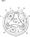
- the section of the pump hose 16 protruding from the cassette housing 15a is threaded into the hose bed 2, as follows with reference to FIG Figures 5 to 8 explained: First, an operator inserts a cassette 15 into the receptacle 13 provided for this on the pump housing 14. After the cassette 15 has been inserted into the receptacle 13 provided for it, the portion of the hose 16 protruding from the cassette housing 15a is manually placed around the guide cylinder 26 of the guide rollers 5 by the operator, as in FIG Figure 5 shown. The tube 16 is then located in the second guide plane B defined by the guide cylinder 26 of the guide rollers 25.
- the length of the section of the tube 16 protruding from the cassette housing 15a is based on the geometry of the Hose pump adapted so that when the hose 16 is placed around the guide cylinder 26 of the guide rollers 5, the hose 16 is brought under a slight pretension and is thereby slightly stretched in its longitudinal direction.
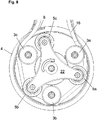
- the area of the hose 16, which is located at the hose inlet 2a of the hose bed 2 is pressed down in the direction of the carrier disk 1. This can be done manually by the operator with a finger, as in Figure 6 indicated.
- the pressing down of the hose 16 in the area of the hose inlet 2a of the hose bed 2 can, however, also take place in an automated manner by means of a mechanical hold-down device.
- the mechanical hold-down device can be, for example, a lever that is movably arranged on the pump housing 14.
- the carrier disk 1 is rotated in the conveying direction (clockwise in the exemplary embodiment shown). This rotation can either be done manually by the operator or automatically by the drive of the hose pump, which is coupled to the carrier disk 1.
- the operator can exert a torque on the carrier disk 1 with one hand via the cover 22.
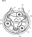
- the carrier disk 1 is rotated (either manually by the operator or automatically by the drive of the hose pump) in the conveying direction until the hose 16 engages in the guide groove 25 of a guide roller 5 (in Figure 7 this is the guide groove 5c).
- the hose 16 By pressing down the hose 16 in the area of the hose inlet 2a of the hose bed 2, the hose 16 is brought into the lower, first guide plane A in this area, in which the guide grooves 25 of the guide rollers 5 are located.
- the guide rollers 5 passes the hose inlet 2a as a result of the rotation of the carrier disk 1 in the conveying direction (here the guide groove 5c, as in FIG Figure 7 shown)
- the section of the hose 16 located in the lower, first guide plane A will therefore engage in the guide groove 25 of the relevant guide roller (here: the guide roller 5c).
- the hose 16 is located completely in the lower, first guide plane A, as in FIG Figure 8 shown, and is thereby completely inserted in the tube bed 2.
- the hose pump is now ready for operation to deliver a fluid located in the hose 16.
- the pump can be operated in its conveying direction F to convey the fluid in the hose.
- the carrier disk 1 in the embodiment shown in the drawing is set in rotation by the drive in the conveying direction (here: clockwise), whereby the squeezing rollers 3 press the hose intermittently with squeezing against the counter bearing 4 and thereby transport the fluid in the hose in the conveying direction .
- the guide rollers 5 provide a secure and constant positioning of the section of the hose 16 in the hose bed 2 securely in that the hose engages in the guide grooves 25 of the guide rollers 5 and is thereby guided.
- the tube 16 When the tube 16 has been properly threaded into the tube bed 2, it is guided through the guide groove 25 of the guide rollers 5 and runs at a small distance and essentially parallel to the surface of the carrier disk 1 and between the outer circumference of the squeezing rollers 3 and the counter bearing 4.
- the (radial) distance between the outer circumference of the squeezing rollers 3 is selected to be smaller than the diameter of the tube 16, so that the tube is clamped between the outer circumference of the squeezing rollers 3 and the counter bearing 4, squeezing the flexible tube.
- the carrier disk 1 is rotated further in the conveying direction until the following guide roller on the carrier disk 1 in the conveying direction (in Figure 7 the guide roller 5b) passes the hose inlet 2a. This can be repeated until the hose 16 engages in a guide groove 25 of one of the guide rollers 5.
- the guide roller 5a has an annular flange 20 which is arranged offset upwards and thus an enlarged insertion cross section in the area of its guide groove 25.
- the enlarged insertion cross-section of the guide roller 5a ensures that the section of the hose 16 that is pressed down in the area of the hose inlet 2a is always grasped by the guide groove 25 of this guide roller 5a and thereby from the upper, second guide plane B to the lower, first Management level A is drawn.
- a corresponding device is expediently provided in the hose pump to monitor the threading process.
- This device for monitoring the threading process can for example comprise a device for detecting the torque acting on the carrier disk 1.
- the rotational resistance of the carrier disk 1 increases, which is why the drive of the hose pump must apply a higher torque to further rotate the carrier disk 1 (at the same rotational speed).
- a signal transmitter outputs a signal which indicates to the operator that the hose 16 has been properly inserted into the hose bed 2.
- the signal transmitter emits a second signal after a specified period of time if the specified torque threshold value is not reached or has not been exceeded within this period is.
- the operator receives the information that the threading process was not successful. In this case, the operator can insert another cassette 15 into the receptacle 13 provided for this purpose on the hose pump and start a new threading process.
- a blockage of the hose pump occurs during a threading process, for example due to the hose 16 becoming tangled, this is also detected via the device for monitoring the threading process and the signal transmitter can output a corresponding signal.
- the threading process is blocked and the operator is requested to insert a new cassette 15.
- the signals can be output, for example, in the form of an acoustic signal or in the form of an indication on a display.
- the hose 16 can be unthreaded from the hose bed 2 via an automatic unthreading routine.
- the carrier disk 1 is rotated by the drive of the peristaltic pump against the conveying direction (that is to say in the counter-clockwise direction in the exemplary embodiment shown).
- the hose arranged at the hose outlet 2b of the hose bed 2 is removed Figure 9 visible survey 8 used. The elevation 8 protrudes above the surface of the carrier disk 1 and lifts the tube 16 somewhat from the surface of the carrier disk 1 in the region of the tube outlet 2a.
- the hose 16 With further rotation of the carrier disk 1 against the conveying direction, the hose 16 is raised over the entire circumference of the hose bed 2 from the lower, first guide level A into the upper, second guide level B, until after a complete rotation of the carrier disk 1 (by 360 °) in the conveying direction, the hose 16 is located completely and over the entire circumference of the hose bed 2 in the upper, second guide level B (corresponding to the in Figure 5 position shown). In this position, the hose 16 can be pulled upwards from the guide rollers 5 by the operator and removed from the hose pump together with the cassette 15.
- this distance between the guiding or squeezing rollers is 90 °.
- the angular distance between the Squeezing rollers 3 and the guide rollers 5 can expediently be different, as described above, or they can also be equidistant.
- a central cylinder projecting above the surface of the carrier disk 1 can be arranged in the center of the carrier disk 1 coaxially to its axis of rotation, which cylinder surrounds the drive shaft 10 and its outer diameter at least approximately to the outer circumference of the radially further outward squeezing rollers and leadership roles is enough.
- the central cylinder can be designed as a hollow cylinder or also as a solid cylinder and is expediently connected to the carrier disk 1 in a rotationally fixed manner.
- the central cylinder When threading the hose, the central cylinder prevents it from coming to rest on the radially inward-facing side of the guide rollers 5 and therefore cannot be properly threaded into the hose bed 2 between the outer circumference of the squeezing rollers 3 and the counter bearing 4.
- the radial distance between the outer surface of the cylinder and the outer circumference of the guide rollers should be smaller than the diameter of the hose to be inserted into the hose bed.
- the height of the central cylinder (in the axial direction) is expediently adapted to the height of the guide rollers and has at least the same height as the guide rollers.
Landscapes
- Engineering & Computer Science (AREA)
- Mechanical Engineering (AREA)
- General Engineering & Computer Science (AREA)
- Reciprocating Pumps (AREA)
- External Artificial Organs (AREA)
Applications Claiming Priority (1)
| Application Number | Priority Date | Filing Date | Title |
|---|---|---|---|
| DE102020106372.5A DE102020106372A1 (de) | 2020-03-09 | 2020-03-09 | Schlauchpumpe |
Publications (2)
| Publication Number | Publication Date |
|---|---|
| EP3879104A1 true EP3879104A1 (fr) | 2021-09-15 |
| EP3879104B1 EP3879104B1 (fr) | 2023-07-26 |
Family
ID=74625844
Family Applications (1)
| Application Number | Title | Priority Date | Filing Date |
|---|---|---|---|
| EP21157044.5A Active EP3879104B1 (fr) | 2020-03-09 | 2021-02-15 | Pompe péristaltique |
Country Status (6)
| Country | Link |
|---|---|
| US (1) | US11639716B2 (fr) |
| EP (1) | EP3879104B1 (fr) |
| CN (1) | CN113374675B (fr) |
| DE (1) | DE102020106372A1 (fr) |
| ES (1) | ES2956538T3 (fr) |
| RU (1) | RU2770629C1 (fr) |
Families Citing this family (6)
| Publication number | Priority date | Publication date | Assignee | Title |
|---|---|---|---|---|
| JP2023184169A (ja) * | 2022-06-17 | 2023-12-28 | 澁谷工業株式会社 | チューブポンプ |
| CN116006447B (zh) * | 2022-12-22 | 2025-11-18 | 浙江小伦智能制造股份有限公司 | 可调式蠕动泵 |
| CN116085251B (zh) * | 2023-03-03 | 2025-11-14 | 深圳市巨鼎医疗股份有限公司 | 一种蠕动泵软管拆装方法 |
| DE102023115055A1 (de) * | 2023-06-07 | 2024-12-12 | B.Braun Avitum Ag | Schlauchrollenpumpe |
| CN118009105B (zh) * | 2024-04-07 | 2024-07-09 | 山西建筑工程集团有限公司 | 一种具有对管线固定作用的建筑施工管线支架 |
| CN119367648A (zh) * | 2024-11-04 | 2025-01-28 | 广州君霖医疗科技有限公司 | 一种蠕动泵自动上下管机构 |
Citations (6)
| Publication number | Priority date | Publication date | Assignee | Title |
|---|---|---|---|---|
| DE2162998A1 (de) * | 1971-12-18 | 1973-06-20 | Siegfried Klusch | Peristaltik-schlauchpumpe fuer extracorporale blutkreislaeufe |
| US20090263256A1 (en) * | 2005-04-07 | 2009-10-22 | Bobo Marion H | Head for a peristaltic pump |
| EP2542781A1 (fr) | 2010-03-01 | 2013-01-09 | Ulrich GmbH & Co. KG | Pompe à tuyau |
| US20130045122A1 (en) * | 2010-03-01 | 2013-02-21 | Ulrich Gmbh & Co. Kg | Peristaltic pump |
| EP2924288A2 (fr) | 2014-03-27 | 2015-09-30 | Ulrich GmbH & Co. KG | Pompe tubulaire doté d'un dispositif de sortie de courant de circulation |
| DE202016101907U1 (de) | 2016-04-11 | 2017-07-12 | Ulrich Gmbh & Co. Kg | Schlauchpumpe |
Family Cites Families (8)
| Publication number | Priority date | Publication date | Assignee | Title |
|---|---|---|---|---|
| US2987004A (en) * | 1955-07-29 | 1961-06-06 | Jerome L Murray | Fluid pressure device |
| US3841799A (en) * | 1971-08-23 | 1974-10-15 | East West Med Prod | Medical cassette pump |
| US5387088A (en) * | 1994-01-18 | 1995-02-07 | Haemonetics Corporation | Peristaltic pump tube loading assembly |
| US7223079B2 (en) * | 2003-07-28 | 2007-05-29 | The Coca-Cola Company | Quick loading peristaltic pump |
| JP3750689B1 (ja) * | 2005-02-04 | 2006-03-01 | セイコーエプソン株式会社 | 流体輸送装置及び流体輸送器 |
| US9869308B2 (en) | 2016-04-26 | 2018-01-16 | Orbis Wheels, Inc. | Centerless pump |
| WO2018013088A1 (fr) * | 2016-07-12 | 2018-01-18 | Hewlett-Packard Development Company, L.P. | Pompage d'encre |
| CN107725343B (zh) * | 2017-11-09 | 2024-01-30 | 四川君汇科技有限公司 | 组合式蠕动泵及组合定位安装方法 |
-
2020
- 2020-03-09 DE DE102020106372.5A patent/DE102020106372A1/de active Pending
-
2021
- 2021-02-15 ES ES21157044T patent/ES2956538T3/es active Active
- 2021-02-15 EP EP21157044.5A patent/EP3879104B1/fr active Active
- 2021-03-03 RU RU2021105481A patent/RU2770629C1/ru active
- 2021-03-08 CN CN202110251836.9A patent/CN113374675B/zh active Active
- 2021-03-08 US US17/195,018 patent/US11639716B2/en active Active
Patent Citations (7)
| Publication number | Priority date | Publication date | Assignee | Title |
|---|---|---|---|---|
| DE2162998A1 (de) * | 1971-12-18 | 1973-06-20 | Siegfried Klusch | Peristaltik-schlauchpumpe fuer extracorporale blutkreislaeufe |
| US20090263256A1 (en) * | 2005-04-07 | 2009-10-22 | Bobo Marion H | Head for a peristaltic pump |
| EP2542781A1 (fr) | 2010-03-01 | 2013-01-09 | Ulrich GmbH & Co. KG | Pompe à tuyau |
| US20130045122A1 (en) * | 2010-03-01 | 2013-02-21 | Ulrich Gmbh & Co. Kg | Peristaltic pump |
| EP2924288A2 (fr) | 2014-03-27 | 2015-09-30 | Ulrich GmbH & Co. KG | Pompe tubulaire doté d'un dispositif de sortie de courant de circulation |
| DE202016101907U1 (de) | 2016-04-11 | 2017-07-12 | Ulrich Gmbh & Co. Kg | Schlauchpumpe |
| EP3232059A2 (fr) | 2016-04-11 | 2017-10-18 | Ulrich GmbH & Co. KG | Pompe tubulaire |
Also Published As
| Publication number | Publication date |
|---|---|
| RU2770629C1 (ru) | 2022-04-19 |
| EP3879104B1 (fr) | 2023-07-26 |
| CN113374675B (zh) | 2023-07-04 |
| ES2956538T3 (es) | 2023-12-22 |
| BR102021004302A2 (pt) | 2021-09-21 |
| CN113374675A (zh) | 2021-09-10 |
| US20210277884A1 (en) | 2021-09-09 |
| US11639716B2 (en) | 2023-05-02 |
| DE102020106372A1 (de) | 2021-09-09 |
Similar Documents
| Publication | Publication Date | Title |
|---|---|---|
| EP3879104B1 (fr) | Pompe péristaltique | |
| EP3232059B1 (fr) | Pompe tubulaire | |
| DE2900743C2 (fr) | ||
| DE60309042T2 (de) | Vortriebssystem für spritzenkolbenstangen | |
| DE68911618T2 (de) | Pumpenvorrichtung für Spritzen. | |
| DE60208131T2 (de) | Öffnungssystem für eine Kappe | |
| DE3326784C2 (de) | Peristaltisch arbeitende Rollenpumpe | |
| DE69626140T2 (de) | Peristaltische pumpe sowie flüssigkeitsabgabeset | |
| DE2352157C3 (de) | Bindevorrichtung zum Umbinden von Bündeln mit Bindedraht | |
| DE202020101287U1 (de) | Schlauchpumpe | |
| EP2924288B1 (fr) | Pompe tubulaire doté d'un dispositif de sortie de courant de circulation | |
| DE3708517A1 (de) | Schlauchpumpe | |
| WO2011107179A1 (fr) | Pompe péristaltique à engrenage planétaire | |
| EP2682607B1 (fr) | Pompe à rouleau tubulaire avec logement de tuyau pivotant et appareil médical pour le traitement extracorporel du sang | |
| WO2010040521A1 (fr) | Dispositif pour ouvrir une ligne | |
| DE2461622C3 (de) | Vorrichtung zur Übergabe von Spinnhülsen | |
| DE2461621B2 (de) | Fadenschneidvorrichtung an ringspinn- und ringzwirnmaschinen | |
| DE2747771A1 (de) | Spanndorn fuer eine huelse als spulentraeger | |
| CH637227A5 (de) | Kopiergeraet mit einer auf eine huelse gewickelten papierrolle und huelse fuer das kopiergeraet. | |
| EP2138623B1 (fr) | Crochet pour une machine à coudre à double point noué | |
| EP0858733A1 (fr) | Dispositif de fixation des ficelles | |
| DE3226492A1 (de) | Vorrichtung zum ordnen von muenzen | |
| DE69917703T2 (de) | Verfahren zur Herstellung einer spiralförmigen Dichtung und Vorrichtung und Einrichtung zur Herstellung derselben | |
| DE3326785A1 (de) | Pumpenrotor fuer peristaltisch arbeitende rollenpumpen | |
| DE19517439B4 (de) | Vorrichtung zum Öffnen von mit Kappen oder Stopfen verschlossenen Behältnissen |
Legal Events
| Date | Code | Title | Description |
|---|---|---|---|
| PUAI | Public reference made under article 153(3) epc to a published international application that has entered the european phase |
Free format text: ORIGINAL CODE: 0009012 |
|
| STAA | Information on the status of an ep patent application or granted ep patent |
Free format text: STATUS: THE APPLICATION HAS BEEN PUBLISHED |
|
| AK | Designated contracting states |
Kind code of ref document: A1 Designated state(s): AL AT BE BG CH CY CZ DE DK EE ES FI FR GB GR HR HU IE IS IT LI LT LU LV MC MK MT NL NO PL PT RO RS SE SI SK SM TR |
|
| STAA | Information on the status of an ep patent application or granted ep patent |
Free format text: STATUS: REQUEST FOR EXAMINATION WAS MADE |
|
| 17P | Request for examination filed |
Effective date: 20220315 |
|
| RBV | Designated contracting states (corrected) |
Designated state(s): AL AT BE BG CH CY CZ DE DK EE ES FI FR GB GR HR HU IE IS IT LI LT LU LV MC MK MT NL NO PL PT RO RS SE SI SK SM TR |
|
| GRAP | Despatch of communication of intention to grant a patent |
Free format text: ORIGINAL CODE: EPIDOSNIGR1 |
|
| STAA | Information on the status of an ep patent application or granted ep patent |
Free format text: STATUS: GRANT OF PATENT IS INTENDED |
|
| INTG | Intention to grant announced |
Effective date: 20230509 |
|
| GRAS | Grant fee paid |
Free format text: ORIGINAL CODE: EPIDOSNIGR3 |
|
| GRAA | (expected) grant |
Free format text: ORIGINAL CODE: 0009210 |
|
| STAA | Information on the status of an ep patent application or granted ep patent |
Free format text: STATUS: THE PATENT HAS BEEN GRANTED |
|
| AK | Designated contracting states |
Kind code of ref document: B1 Designated state(s): AL AT BE BG CH CY CZ DE DK EE ES FI FR GB GR HR HU IE IS IT LI LT LU LV MC MK MT NL NO PL PT RO RS SE SI SK SM TR |
|
| REG | Reference to a national code |
Ref country code: CH Ref legal event code: EP |
|
| REG | Reference to a national code |
Ref country code: DE Ref legal event code: R096 Ref document number: 502021001053 Country of ref document: DE |
|
| REG | Reference to a national code |
Ref country code: IE Ref legal event code: FG4D Free format text: LANGUAGE OF EP DOCUMENT: GERMAN |
|
| REG | Reference to a national code |
Ref country code: LT Ref legal event code: MG9D |
|
| REG | Reference to a national code |
Ref country code: NL Ref legal event code: MP Effective date: 20230726 |
|
| REG | Reference to a national code |
Ref country code: ES Ref legal event code: FG2A Ref document number: 2956538 Country of ref document: ES Kind code of ref document: T3 Effective date: 20231222 |
|
| PG25 | Lapsed in a contracting state [announced via postgrant information from national office to epo] |
Ref country code: NL Free format text: LAPSE BECAUSE OF FAILURE TO SUBMIT A TRANSLATION OF THE DESCRIPTION OR TO PAY THE FEE WITHIN THE PRESCRIBED TIME-LIMIT Effective date: 20230726 |
|
| PG25 | Lapsed in a contracting state [announced via postgrant information from national office to epo] |
Ref country code: GR Free format text: LAPSE BECAUSE OF FAILURE TO SUBMIT A TRANSLATION OF THE DESCRIPTION OR TO PAY THE FEE WITHIN THE PRESCRIBED TIME-LIMIT Effective date: 20231027 |
|
| PG25 | Lapsed in a contracting state [announced via postgrant information from national office to epo] |
Ref country code: IS Free format text: LAPSE BECAUSE OF FAILURE TO SUBMIT A TRANSLATION OF THE DESCRIPTION OR TO PAY THE FEE WITHIN THE PRESCRIBED TIME-LIMIT Effective date: 20231126 |
|
| PG25 | Lapsed in a contracting state [announced via postgrant information from national office to epo] |
Ref country code: SE Free format text: LAPSE BECAUSE OF FAILURE TO SUBMIT A TRANSLATION OF THE DESCRIPTION OR TO PAY THE FEE WITHIN THE PRESCRIBED TIME-LIMIT Effective date: 20230726 Ref country code: RS Free format text: LAPSE BECAUSE OF FAILURE TO SUBMIT A TRANSLATION OF THE DESCRIPTION OR TO PAY THE FEE WITHIN THE PRESCRIBED TIME-LIMIT Effective date: 20230726 Ref country code: PT Free format text: LAPSE BECAUSE OF FAILURE TO SUBMIT A TRANSLATION OF THE DESCRIPTION OR TO PAY THE FEE WITHIN THE PRESCRIBED TIME-LIMIT Effective date: 20231127 Ref country code: NO Free format text: LAPSE BECAUSE OF FAILURE TO SUBMIT A TRANSLATION OF THE DESCRIPTION OR TO PAY THE FEE WITHIN THE PRESCRIBED TIME-LIMIT Effective date: 20231026 Ref country code: LV Free format text: LAPSE BECAUSE OF FAILURE TO SUBMIT A TRANSLATION OF THE DESCRIPTION OR TO PAY THE FEE WITHIN THE PRESCRIBED TIME-LIMIT Effective date: 20230726 Ref country code: LT Free format text: LAPSE BECAUSE OF FAILURE TO SUBMIT A TRANSLATION OF THE DESCRIPTION OR TO PAY THE FEE WITHIN THE PRESCRIBED TIME-LIMIT Effective date: 20230726 Ref country code: IS Free format text: LAPSE BECAUSE OF FAILURE TO SUBMIT A TRANSLATION OF THE DESCRIPTION OR TO PAY THE FEE WITHIN THE PRESCRIBED TIME-LIMIT Effective date: 20231126 Ref country code: HR Free format text: LAPSE BECAUSE OF FAILURE TO SUBMIT A TRANSLATION OF THE DESCRIPTION OR TO PAY THE FEE WITHIN THE PRESCRIBED TIME-LIMIT Effective date: 20230726 Ref country code: GR Free format text: LAPSE BECAUSE OF FAILURE TO SUBMIT A TRANSLATION OF THE DESCRIPTION OR TO PAY THE FEE WITHIN THE PRESCRIBED TIME-LIMIT Effective date: 20231027 Ref country code: FI Free format text: LAPSE BECAUSE OF FAILURE TO SUBMIT A TRANSLATION OF THE DESCRIPTION OR TO PAY THE FEE WITHIN THE PRESCRIBED TIME-LIMIT Effective date: 20230726 |
|
| PG25 | Lapsed in a contracting state [announced via postgrant information from national office to epo] |
Ref country code: PL Free format text: LAPSE BECAUSE OF FAILURE TO SUBMIT A TRANSLATION OF THE DESCRIPTION OR TO PAY THE FEE WITHIN THE PRESCRIBED TIME-LIMIT Effective date: 20230726 |
|
| REG | Reference to a national code |
Ref country code: DE Ref legal event code: R097 Ref document number: 502021001053 Country of ref document: DE |
|
| PG25 | Lapsed in a contracting state [announced via postgrant information from national office to epo] |
Ref country code: SM Free format text: LAPSE BECAUSE OF FAILURE TO SUBMIT A TRANSLATION OF THE DESCRIPTION OR TO PAY THE FEE WITHIN THE PRESCRIBED TIME-LIMIT Effective date: 20230726 Ref country code: RO Free format text: LAPSE BECAUSE OF FAILURE TO SUBMIT A TRANSLATION OF THE DESCRIPTION OR TO PAY THE FEE WITHIN THE PRESCRIBED TIME-LIMIT Effective date: 20230726 Ref country code: EE Free format text: LAPSE BECAUSE OF FAILURE TO SUBMIT A TRANSLATION OF THE DESCRIPTION OR TO PAY THE FEE WITHIN THE PRESCRIBED TIME-LIMIT Effective date: 20230726 Ref country code: DK Free format text: LAPSE BECAUSE OF FAILURE TO SUBMIT A TRANSLATION OF THE DESCRIPTION OR TO PAY THE FEE WITHIN THE PRESCRIBED TIME-LIMIT Effective date: 20230726 Ref country code: CZ Free format text: LAPSE BECAUSE OF FAILURE TO SUBMIT A TRANSLATION OF THE DESCRIPTION OR TO PAY THE FEE WITHIN THE PRESCRIBED TIME-LIMIT Effective date: 20230726 Ref country code: SK Free format text: LAPSE BECAUSE OF FAILURE TO SUBMIT A TRANSLATION OF THE DESCRIPTION OR TO PAY THE FEE WITHIN THE PRESCRIBED TIME-LIMIT Effective date: 20230726 |
|
| PLBE | No opposition filed within time limit |
Free format text: ORIGINAL CODE: 0009261 |
|
| STAA | Information on the status of an ep patent application or granted ep patent |
Free format text: STATUS: NO OPPOSITION FILED WITHIN TIME LIMIT |
|
| 26N | No opposition filed |
Effective date: 20240429 |
|
| PG25 | Lapsed in a contracting state [announced via postgrant information from national office to epo] |
Ref country code: SI Free format text: LAPSE BECAUSE OF FAILURE TO SUBMIT A TRANSLATION OF THE DESCRIPTION OR TO PAY THE FEE WITHIN THE PRESCRIBED TIME-LIMIT Effective date: 20230726 |
|
| PG25 | Lapsed in a contracting state [announced via postgrant information from national office to epo] |
Ref country code: MC Free format text: LAPSE BECAUSE OF FAILURE TO SUBMIT A TRANSLATION OF THE DESCRIPTION OR TO PAY THE FEE WITHIN THE PRESCRIBED TIME-LIMIT Effective date: 20230726 |
|
| REG | Reference to a national code |
Ref country code: CH Ref legal event code: PL |
|
| PG25 | Lapsed in a contracting state [announced via postgrant information from national office to epo] |
Ref country code: LU Free format text: LAPSE BECAUSE OF NON-PAYMENT OF DUE FEES Effective date: 20240215 |
|
| PG25 | Lapsed in a contracting state [announced via postgrant information from national office to epo] |
Ref country code: CH Free format text: LAPSE BECAUSE OF NON-PAYMENT OF DUE FEES Effective date: 20240229 |
|
| PG25 | Lapsed in a contracting state [announced via postgrant information from national office to epo] |
Ref country code: LU Free format text: LAPSE BECAUSE OF NON-PAYMENT OF DUE FEES Effective date: 20240215 Ref country code: CH Free format text: LAPSE BECAUSE OF NON-PAYMENT OF DUE FEES Effective date: 20240229 |
|
| PG25 | Lapsed in a contracting state [announced via postgrant information from national office to epo] |
Ref country code: BG Free format text: LAPSE BECAUSE OF FAILURE TO SUBMIT A TRANSLATION OF THE DESCRIPTION OR TO PAY THE FEE WITHIN THE PRESCRIBED TIME-LIMIT Effective date: 20230726 |
|
| PG25 | Lapsed in a contracting state [announced via postgrant information from national office to epo] |
Ref country code: BG Free format text: LAPSE BECAUSE OF FAILURE TO SUBMIT A TRANSLATION OF THE DESCRIPTION OR TO PAY THE FEE WITHIN THE PRESCRIBED TIME-LIMIT Effective date: 20230726 |
|
| REG | Reference to a national code |
Ref country code: BE Ref legal event code: MM Effective date: 20240229 |
|
| PG25 | Lapsed in a contracting state [announced via postgrant information from national office to epo] |
Ref country code: BE Free format text: LAPSE BECAUSE OF NON-PAYMENT OF DUE FEES Effective date: 20240229 |
|
| PG25 | Lapsed in a contracting state [announced via postgrant information from national office to epo] |
Ref country code: IE Free format text: LAPSE BECAUSE OF NON-PAYMENT OF DUE FEES Effective date: 20240215 |
|
| PG25 | Lapsed in a contracting state [announced via postgrant information from national office to epo] |
Ref country code: IE Free format text: LAPSE BECAUSE OF NON-PAYMENT OF DUE FEES Effective date: 20240215 Ref country code: BE Free format text: LAPSE BECAUSE OF NON-PAYMENT OF DUE FEES Effective date: 20240229 |
|
| PGFP | Annual fee paid to national office [announced via postgrant information from national office to epo] |
Ref country code: TR Payment date: 20250206 Year of fee payment: 5 |
|
| PG25 | Lapsed in a contracting state [announced via postgrant information from national office to epo] |
Ref country code: CY Free format text: LAPSE BECAUSE OF FAILURE TO SUBMIT A TRANSLATION OF THE DESCRIPTION OR TO PAY THE FEE WITHIN THE PRESCRIBED TIME-LIMIT; INVALID AB INITIO Effective date: 20210215 |
|
| PG25 | Lapsed in a contracting state [announced via postgrant information from national office to epo] |
Ref country code: HU Free format text: LAPSE BECAUSE OF FAILURE TO SUBMIT A TRANSLATION OF THE DESCRIPTION OR TO PAY THE FEE WITHIN THE PRESCRIBED TIME-LIMIT; INVALID AB INITIO Effective date: 20210215 |
|
| PGFP | Annual fee paid to national office [announced via postgrant information from national office to epo] |
Ref country code: GB Payment date: 20260219 Year of fee payment: 6 |
|
| PGFP | Annual fee paid to national office [announced via postgrant information from national office to epo] |
Ref country code: ES Payment date: 20260319 Year of fee payment: 6 |
|
| PGFP | Annual fee paid to national office [announced via postgrant information from national office to epo] |
Ref country code: DE Payment date: 20260306 Year of fee payment: 6 |
|
| PGFP | Annual fee paid to national office [announced via postgrant information from national office to epo] |
Ref country code: AT Payment date: 20260216 Year of fee payment: 6 |
|
| PGFP | Annual fee paid to national office [announced via postgrant information from national office to epo] |
Ref country code: IT Payment date: 20260227 Year of fee payment: 6 |
|
| PGFP | Annual fee paid to national office [announced via postgrant information from national office to epo] |
Ref country code: FR Payment date: 20260219 Year of fee payment: 6 |