EP3879121B1 - Support pour un palier de pompe électrique et pompe électrique dotée d'un tel support - Google Patents
Support pour un palier de pompe électrique et pompe électrique dotée d'un tel support Download PDFInfo
- Publication number
- EP3879121B1 EP3879121B1 EP21152603.3A EP21152603A EP3879121B1 EP 3879121 B1 EP3879121 B1 EP 3879121B1 EP 21152603 A EP21152603 A EP 21152603A EP 3879121 B1 EP3879121 B1 EP 3879121B1
- Authority
- EP
- European Patent Office
- Prior art keywords
- support
- bearing
- receptacle
- electric pump
- axis
- Prior art date
- Legal status (The legal status is an assumption and is not a legal conclusion. Google has not performed a legal analysis and makes no representation as to the accuracy of the status listed.)
- Active
Links
Images


Classifications
-
- F—MECHANICAL ENGINEERING; LIGHTING; HEATING; WEAPONS; BLASTING
- F04—POSITIVE - DISPLACEMENT MACHINES FOR LIQUIDS; PUMPS FOR LIQUIDS OR ELASTIC FLUIDS
- F04D—NON-POSITIVE-DISPLACEMENT PUMPS
- F04D29/00—Details, component parts, or accessories
- F04D29/04—Shafts or bearings, or assemblies thereof
- F04D29/046—Bearings
-
- F—MECHANICAL ENGINEERING; LIGHTING; HEATING; WEAPONS; BLASTING
- F04—POSITIVE - DISPLACEMENT MACHINES FOR LIQUIDS; PUMPS FOR LIQUIDS OR ELASTIC FLUIDS
- F04D—NON-POSITIVE-DISPLACEMENT PUMPS
- F04D29/00—Details, component parts, or accessories
- F04D29/04—Shafts or bearings, or assemblies thereof
- F04D29/046—Bearings
- F04D29/0462—Bearing cartridges
-
- F—MECHANICAL ENGINEERING; LIGHTING; HEATING; WEAPONS; BLASTING
- F04—POSITIVE - DISPLACEMENT MACHINES FOR LIQUIDS; PUMPS FOR LIQUIDS OR ELASTIC FLUIDS
- F04D—NON-POSITIVE-DISPLACEMENT PUMPS
- F04D1/00—Radial-flow pumps, e.g. centrifugal pumps; Helico-centrifugal pumps
- F04D1/06—Multi-stage pumps
-
- F—MECHANICAL ENGINEERING; LIGHTING; HEATING; WEAPONS; BLASTING
- F04—POSITIVE - DISPLACEMENT MACHINES FOR LIQUIDS; PUMPS FOR LIQUIDS OR ELASTIC FLUIDS
- F04D—NON-POSITIVE-DISPLACEMENT PUMPS
- F04D13/00—Pumping installations or systems
- F04D13/02—Units comprising pumps and their driving means
- F04D13/06—Units comprising pumps and their driving means the pump being electrically driven
-
- F—MECHANICAL ENGINEERING; LIGHTING; HEATING; WEAPONS; BLASTING
- F04—POSITIVE - DISPLACEMENT MACHINES FOR LIQUIDS; PUMPS FOR LIQUIDS OR ELASTIC FLUIDS
- F04D—NON-POSITIVE-DISPLACEMENT PUMPS
- F04D29/00—Details, component parts, or accessories
- F04D29/02—Selection of particular materials
- F04D29/026—Selection of particular materials especially adapted for liquid pumps
-
- F—MECHANICAL ENGINEERING; LIGHTING; HEATING; WEAPONS; BLASTING
- F04—POSITIVE - DISPLACEMENT MACHINES FOR LIQUIDS; PUMPS FOR LIQUIDS OR ELASTIC FLUIDS
- F04D—NON-POSITIVE-DISPLACEMENT PUMPS
- F04D29/00—Details, component parts, or accessories
- F04D29/04—Shafts or bearings, or assemblies thereof
- F04D29/046—Bearings
- F04D29/049—Roller bearings
-
- F—MECHANICAL ENGINEERING; LIGHTING; HEATING; WEAPONS; BLASTING
- F04—POSITIVE - DISPLACEMENT MACHINES FOR LIQUIDS; PUMPS FOR LIQUIDS OR ELASTIC FLUIDS
- F04D—NON-POSITIVE-DISPLACEMENT PUMPS
- F04D29/00—Details, component parts, or accessories
- F04D29/08—Sealings
- F04D29/10—Shaft sealings
- F04D29/106—Shaft sealings especially adapted for liquid pumps
-
- F—MECHANICAL ENGINEERING; LIGHTING; HEATING; WEAPONS; BLASTING
- F04—POSITIVE - DISPLACEMENT MACHINES FOR LIQUIDS; PUMPS FOR LIQUIDS OR ELASTIC FLUIDS
- F04D—NON-POSITIVE-DISPLACEMENT PUMPS
- F04D29/00—Details, component parts, or accessories
- F04D29/40—Casings; Connections of working fluid
- F04D29/42—Casings; Connections of working fluid for radial or helico-centrifugal pumps
- F04D29/426—Casings; Connections of working fluid for radial or helico-centrifugal pumps especially adapted for liquid pumps
-
- F—MECHANICAL ENGINEERING; LIGHTING; HEATING; WEAPONS; BLASTING
- F04—POSITIVE - DISPLACEMENT MACHINES FOR LIQUIDS; PUMPS FOR LIQUIDS OR ELASTIC FLUIDS
- F04D—NON-POSITIVE-DISPLACEMENT PUMPS
- F04D29/00—Details, component parts, or accessories
- F04D29/60—Mounting; Assembling; Disassembling
- F04D29/62—Mounting; Assembling; Disassembling of radial or helico-centrifugal pumps
- F04D29/628—Mounting; Assembling; Disassembling of radial or helico-centrifugal pumps especially adapted for liquid pumps
Definitions
- the present invention relates to a support for a bearing for electric pump.
- the invention also relates to an electric pump with such a bearing support.
- An electric pump is a device for pumping a liquid, which comprises a wet region, which has intake and delivery ducts, in which one or more impellers are submerged, diffusers being interleaved between said impellers, which are keyed on a rotating shaft turned by an electric motor.
- This electric motor comprises a stator and a rotor, from which the rotating shaft extends.
- the electric motor see e.g. EP 3290712 A1 , is contained in a substantially tubular motor housing, which is isolated from the wet region, on the rotating shaft, by means of a mechanical seal.
- This mechanical seal surrounds the rotating shaft and is carried by an annular supporting element which also surrounds the rotating shaft at the interface between the motor housing and the wet region.
- the rotating shaft supports two bearings between which the rotor of the electric motor is interposed.
- the two bearings are adapted to keep the rotating shaft, and therefore the rotor, in axial alignment during operation and when not in use.
- one of the two bearings is arranged, inside the motor housing, proximate to the interface region between the latter and the wet region.
- the bearing supporting element proximate to the wet region is made of metallic material, usually aluminum, while the supporting element of the mechanical seal is made of plastic material.
- the support of the bearing made of metal, is centered on the support of the mechanical seal, made of plastic material.
- the support for the mechanical seal made of plastic material entails that it is impossible to achieve dimensional tolerances of the centering between the two supports that would be achieved by using other materials.
- a support for the bearing and of a support for the sealing element which are separate and are proximate to/at the interface between the wet region and the motor housing can determine a non-perfect coaxiality between the two supports, also as a result of deformations on the support for the mechanical seal made of plastic material, and therefore the generation of bending moments on the rotating shaft, with consequent malfunctioning of the electric pump.
- a non-perfect coaxiality between the support of the mechanical seal and the support of the bearing reduces the operating life of the seal and therefore of the electric pump.
- the aim of the present invention is to provide a support for a bearing for electric pump that is capable of improving the background art in one or more of the aspects mentioned above.
- an object of the invention is to provide a support for a bearing for electric pump that allows to reduce the number of components of the electric pump.
- Another object of the invention is to devise a support for a mechanical seal for an electric pump that is less subject to deformations than similar bearing supports of a known type.
- Another object of the invention is to provide a support for a bearing for electric pump that allows to achieve centering dimensional tolerances with the support for the mechanical seal which are lower than those achieved by similar supports of a known type.
- a further object of the invention is to devise a support for a bearing for electric pump that allows a better coaxiality with the support of the sealing element for the wet region than similar supports of a known type and therefore allows to reduce the bending moments generated on the rotating shaft.
- a still further object of the present invention is to overcome the drawbacks of the background art in a manner that is alternative to any existing solutions.
- Another object of the invention is to provide a support for a bearing for electric pump that is highly reliable, relatively easy to provide and at competitive costs.
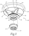
- a support for a bearing 12 for electric pump 50 according to the invention is generally designated by the reference numeral 10.
- the support 10 has a contoured portion which forms in a single body:
- the invention provides a common support for the bearing and the mechanical seal.
- the receptacle 13 for the sealing element 14 is arranged inside a flange element 26 which comprises a disk-like portion 15 provided with a first through hole 25 and a surface from which an annular portion 16 extends which is coaxial to the disk-like portion 15 and surrounds the first through hole 25.
- the sealing element 14 which is constituted by a mechanical seal, is inserted into the annular portion 16 and is seated in the first through hole at/proximate to the disk-like portion 15.
- the support 10 is made of metallic material, such as for example aluminum, and has an element 17 for covering the annular portion 16, which forms the receptacle 13 for the sealing element 14.
- the sealing element 14 is accommodated inside the covering element 17 in the first through hole 25 of the annular portion 16.
- the covering element 17 is made of metallic material, advantageously stainless steel, and is adapted to protect the support 10 from water, being arranged at the interface between the wet region 51 of the electric pump 50 and its motor housing 52.
- the covering element 17 is a first covering element
- the sealing element 14 rests inside the covering element 17 and is surrounded by it.
- the support 10 comprises, at the opposite end with respect to the end provided with the receptacle 13 for the sealing element 14, a tray element 19 which has a circular profile with a flanged perimetric rim 20.
- the tray element 19 comprises a base 21 and a side wall 22 from which the flanged rim 20 is extended.
- the base 21 is provided with a second through hole 23 for the insertion of the rotating shaft 18 of the electric pump 50.
- the inside diameter of the tubular portion 24 is comparable with the outside diameter of the bearing 12 and is greater than the diameter of the second through hole 23.
- the bearing 12 is inserted in the tubular portion 24 and is substantially in contact with the base 21 of the tray portion 19.
- the tubular portion 24, the tray element 19, the disk-like portion 15 and the annular portion 16 are coaxial and their axis coincides with the extension axis X of the support 10.
- the flange element 26 and the tray element 19 are connected and joined by one or more bridge elements 27 which give greater stiffness to the support 10.
- These bridge elements 27 have a substantially triangular profile.
- the bridge elements 27 are four, arranged in a radial manner with respect to the extension axis X of the support 10 and mutually equidistant.
- the first through hole 25 and the second through hole 23 form a single passage for the rotating shaft 18 of the electric pump 50, around which the bridge elements 27 are arranged.
- the bearing 12 and the sealing element 14 are arranged at opposite ends and are directed toward the outside of the support 10, therefore toward opposite sides of the support 10.
- Figure 2 shows a cross-section of an electric pump 50 comprising a support 10 according to the invention.
- the electric pump 50 has, in the configuration for use, a vertical extension and comprises, from the bottom upward:
- One or more impellers 54 keyed on the rotating shaft 18 are arranged in the wet region 51.
- a motor is arranged inside the motor housing 52 and comprises a rotor 55 for the movement of the rotating shaft 18, which is keyed thereon, and a stator 56 which surrounds the rotor 55.
- the rotating shaft 18 is kept in axial alignment by means of two bearings arranged at the ends of the rotor 55, respectively:
- the support 10 for the bearing 12, as described above, is arranged inside the electric pump 50, at the interface between the wet region 51 and the motor housing 52.
- the sealing element 14 is keyed on the rotating shaft 18, at the interface between the wet region 51 and the motor housing 52, and hinders the passage of the liquid from the wet region 51 to the motor housing 52.
- the invention achieves the intended aim and objects, providing a support for a bearing for electric pump which allows to reduce the number of components of the electric pump.
- the invention provides a common support to the bearing and to the mechanical seal which is completely made of metallic material.
- the invention provides a support for a bearing for electric pump which allows to achieve centering dimensional tolerances with the support for the mechanical seal that are smaller than those achieved by similar supports of a known type, since it is provided monolithically with the support for the mechanical seal and is made of metallic material.
- the invention provides a support for a bearing for electric pump which allows a better coaxiality with the support of the sealing element for the wet region than similar supports of a known type and therefore allows to reduce the bending moments generated on the rotating shaft, since its flange element, which defines the receptacle for the sealing element, and its tubular element, which defines the receptacle for the bearing, are coaxial.
- the materials used may be any according to the requirements and the state of the art.
Landscapes
- Engineering & Computer Science (AREA)
- Mechanical Engineering (AREA)
- General Engineering & Computer Science (AREA)
- Structures Of Non-Positive Displacement Pumps (AREA)
Claims (11)
- Support (10) pour un palier (12) pour une pompe électrique (50), ayant une partie profilée qui forme dans un seul corps; et comprenant:- un logement (11) pour ledit palier (12),- un logement (13) pour un élément d'étanchéité (14) ledit réceptacle (13) pour ledit élément d'étanchéité (14) étant agencé à l'intérieur d'un élément de bride (26) qui comprend:- une partie en forme de disque (15) munie d'un premier trou traversant (25)- une partie annulaire (16), qui est coaxiale à ladite partie en forme de disque (15) et entoure ledit premier trou traversant (25);le support (10) étant pourvu d'un élément (17) pour recouvrir ladite partie annulaire (16), qui forme ledit réceptacle (13) pour ledit élément d'étanchéité (14), dans lequel ledit élément de recouvrement (17):- est réalisé en matériau métallique, de préférence en acier inoxydable;- est co-moulé avec ledit élément de bride (26),- est complémentaire de ladite portion annulaire (16),- a une forme qui reproduit la forme de ladite partie annulaire (16).
- Support (10) selon la revendication 1, caractérisé en ce qu'il est réalisé en matériau métallique.
- Support (10) selon la revendication 1, caractérisé en ce que ledit réceptacle (11) pour ledit palier (12) et ledit réceptacle (13) pour ledit élément d'étanchéité (14) sont agencés à deux extrémités opposées dudit support (10) le long son axe d'extension (X), en considérant ledit axe d'extension (X) comme:- un axe central, qui se trouve sur le plan de symétrie dudit support (10),- perpendiculairement aux plans d'agencement dudit logement (11) pour ledit palier (12) et dudit logement (13) pour ledit élément d'étanchéité (14).
- Support (10) selon la revendication 3, caractérisé en ce que, considérant ledit axe d'extension (X), il comprend un élément de plateau (19) qui présente un profil circulaire, à l'opposé de l'extrémité munie dudit réceptacle (13) pour ledit élément d'étanchéité (14).
- Support (10) selon la revendication 4, caractérisé en ce que ledit élément de plateau (19) comprend une base (21) et une paroi latérale (22), ladite base (21) étant pourvue d'un deuxième trou traversant (23).
- Support (10) selon la revendication 4, caractérisé en ce qu' à l'intérieur dudit élément de plateau (19) se trouve une partie tubulaire (24) qui est monolithique avec lui, ladite partie tubulaire (24) constituant le bord latéral dudit réceptacle (11) pour ledit palier (12).
- Support (10) selon la revendication 6, caractérisé en ce que le diamètre intérieur de ladite partie tubulaire (24) est supérieur au diamètre dudit deuxième trou traversant (23).
- Support (10) selon la revendication 6, caractérisé en ce que ladite partie tubulaire (24), ledit élément de plateau (19), ladite partie en forme de disque (15) et ladite partie annulaire (16) sont coaxiaux et leur axe coïncide avec ledit axe d'extension (X) dudit support (10).
- Support (10) selon la revendication 4, caractérisé en ce que ledit élément de rebord (26) et ledit élément de plateau (19) sont reliés et reliés par un ou plusieurs éléments de pont (27).
- Support (10) selon la revendication 9, caractérisé en ce que lesdits un ou plusieurs éléments de pont (27) ont un profil sensiblement triangulaire et sont disposés radialement par rapport audit axe d'extension (X) dudit support (10).
- Pompe électrique (50), comprenant:- une région humide (51), une ou plusieurs hélices (54) calées sur un arbre rotatif (18) étant agencées dans ladite région humide,- un carter moteur (52),- un moteur agencé à l'intérieur dudit carter de moteur (52), ledit moteur comprenant un rotor (55) pour le mouvement dudit arbre rotatif (18),qui est calé dessus, et un stator (56) qui entoure ledit rotor (55),ledit arbre rotatif (18) étant maintenu en alignement axial au moyen de deux paliers agencés aux extrémités dudit rotor (55):- un premier palier (57),- un deuxième palier (12), agencé à l'intérieur dudit carter de moteur (52), à proximité de ladite région humide (51), caractérisé en ce qu'il comprend, à l'interface entre ladite région humide (51) et ledit carter de moteur (52), un support (10) pour le support dudit deuxième palier (12) selon une ou plusieurs des revendications précédentes.
Applications Claiming Priority (1)
| Application Number | Priority Date | Filing Date | Title |
|---|---|---|---|
| IT102020000004873A IT202000004873A1 (it) | 2020-03-09 | 2020-03-09 | Supporto perfezionato per cuscinetto per elettropompa ed elettropompa con un simile supporto |
Publications (3)
| Publication Number | Publication Date |
|---|---|
| EP3879121A1 EP3879121A1 (fr) | 2021-09-15 |
| EP3879121B1 true EP3879121B1 (fr) | 2023-07-26 |
| EP3879121C0 EP3879121C0 (fr) | 2023-07-26 |
Family
ID=70804923
Family Applications (1)
| Application Number | Title | Priority Date | Filing Date |
|---|---|---|---|
| EP21152603.3A Active EP3879121B1 (fr) | 2020-03-09 | 2021-01-20 | Support pour un palier de pompe électrique et pompe électrique dotée d'un tel support |
Country Status (4)
| Country | Link |
|---|---|
| EP (1) | EP3879121B1 (fr) |
| CN (1) | CN113374726B (fr) |
| ES (1) | ES2953315T3 (fr) |
| IT (1) | IT202000004873A1 (fr) |
Family Cites Families (9)
| Publication number | Priority date | Publication date | Assignee | Title |
|---|---|---|---|---|
| JP3587544B2 (ja) * | 1993-08-31 | 2004-11-10 | 株式会社佐山製作所 | 陸上ポンプ |
| JP3008187B2 (ja) * | 1997-08-25 | 2000-02-14 | 株式会社久保田鉄工所 | 水ポンプ及びその製造方法 |
| JP2000045981A (ja) * | 1998-07-29 | 2000-02-15 | Teral Kyokuto Inc | 陸上ポンプ |
| EP2228538B1 (fr) * | 2009-03-10 | 2015-09-16 | Grundfos Management A/S | Agrégat de pompe centrifuge à plusieurs niveaux |
| ITPD20120284A1 (it) * | 2012-10-02 | 2014-04-03 | Dab Pumps Spa | Struttura di elettropompa centrifuga perfezionata |
| CN106122034A (zh) * | 2015-05-07 | 2016-11-16 | 江苏尚宝罗泵业有限公司 | 高效造纸工艺流程泵 |
| IT201600089875A1 (it) * | 2016-09-06 | 2018-03-06 | Calpeda A Spa | Elettropompa centrifuga con camera intermedia, particolarmente adatta al pompaggio di liquidi contenenti impurita’ solide |
| CN106989031A (zh) * | 2017-05-23 | 2017-07-28 | 六安海泉泵业有限公司 | 一种新型潜水排污泵 |
| CN109114037A (zh) * | 2018-10-30 | 2019-01-01 | 江苏优联环境发展有限公司 | 无泄漏轴密封潜水泵 |
-
2020
- 2020-03-09 IT IT102020000004873A patent/IT202000004873A1/it unknown
-
2021
- 2021-01-20 EP EP21152603.3A patent/EP3879121B1/fr active Active
- 2021-01-20 ES ES21152603T patent/ES2953315T3/es active Active
- 2021-03-05 CN CN202110243003.8A patent/CN113374726B/zh active Active
Also Published As
| Publication number | Publication date |
|---|---|
| CN113374726B (zh) | 2025-11-11 |
| CN113374726A (zh) | 2021-09-10 |
| EP3879121C0 (fr) | 2023-07-26 |
| IT202000004873A1 (it) | 2021-09-09 |
| EP3879121A1 (fr) | 2021-09-15 |
| ES2953315T3 (es) | 2023-11-10 |
Similar Documents
| Publication | Publication Date | Title |
|---|---|---|
| US8152484B2 (en) | Engine cooling fan assembly | |
| US7131823B2 (en) | Electrically driven pump and domestic appliance having the pump | |
| CN105308326B (zh) | 泵装置和制造泵装置的安全壳的方法 | |
| US20090081036A1 (en) | Axial flow fan | |
| JP4633396B2 (ja) | 遠心式ポンプ | |
| JP6410831B2 (ja) | 電気式の自動車用冷媒ポンプ | |
| CN109958635B (zh) | 离心风扇 | |
| KR101898348B1 (ko) | 모터 | |
| KR20160005090A (ko) | 펌프 장치 | |
| TW202102781A (zh) | 風扇馬達及其製造方法 | |
| JP2013204784A (ja) | 軸受装置および送風ファン | |
| US20160208805A1 (en) | Centrifugal pump | |
| CN104040182B (zh) | 泵机组 | |
| EP3879121B1 (fr) | Support pour un palier de pompe électrique et pompe électrique dotée d'un tel support | |
| KR20210007929A (ko) | 팬모터 및 그 제조방법 | |
| CN107733150A (zh) | 用于流体循环器的改进的电动机 | |
| KR102153561B1 (ko) | 원심형 혈액 펌프 | |
| US8591204B2 (en) | Turbo-molecular pump | |
| JP5934515B2 (ja) | 排水ポンプ | |
| US7261524B2 (en) | Rotation support with improved thrust-bearing for rotors of pump electric motors | |
| US10156238B2 (en) | Centrifugal pump | |
| CN105090054B (zh) | 离心泵 | |
| JP5977693B2 (ja) | インペラおよびウォーターポンプ | |
| US20100232967A1 (en) | Centrifugal fan | |
| US2862452A (en) | Pumps |
Legal Events
| Date | Code | Title | Description |
|---|---|---|---|
| PUAI | Public reference made under article 153(3) epc to a published international application that has entered the european phase |
Free format text: ORIGINAL CODE: 0009012 |
|
| STAA | Information on the status of an ep patent application or granted ep patent |
Free format text: STATUS: THE APPLICATION HAS BEEN PUBLISHED |
|
| AK | Designated contracting states |
Kind code of ref document: A1 Designated state(s): AL AT BE BG CH CY CZ DE DK EE ES FI FR GB GR HR HU IE IS IT LI LT LU LV MC MK MT NL NO PL PT RO RS SE SI SK SM TR |
|
| STAA | Information on the status of an ep patent application or granted ep patent |
Free format text: STATUS: REQUEST FOR EXAMINATION WAS MADE |
|
| 17P | Request for examination filed |
Effective date: 20220301 |
|
| RBV | Designated contracting states (corrected) |
Designated state(s): AL AT BE BG CH CY CZ DE DK EE ES FI FR GB GR HR HU IE IS IT LI LT LU LV MC MK MT NL NO PL PT RO RS SE SI SK SM TR |
|
| GRAP | Despatch of communication of intention to grant a patent |
Free format text: ORIGINAL CODE: EPIDOSNIGR1 |
|
| STAA | Information on the status of an ep patent application or granted ep patent |
Free format text: STATUS: GRANT OF PATENT IS INTENDED |
|
| INTG | Intention to grant announced |
Effective date: 20230504 |
|
| GRAS | Grant fee paid |
Free format text: ORIGINAL CODE: EPIDOSNIGR3 |
|
| P01 | Opt-out of the competence of the unified patent court (upc) registered |
Effective date: 20230515 |
|
| GRAA | (expected) grant |
Free format text: ORIGINAL CODE: 0009210 |
|
| STAA | Information on the status of an ep patent application or granted ep patent |
Free format text: STATUS: THE PATENT HAS BEEN GRANTED |
|
| AK | Designated contracting states |
Kind code of ref document: B1 Designated state(s): AL AT BE BG CH CY CZ DE DK EE ES FI FR GB GR HR HU IE IS IT LI LT LU LV MC MK MT NL NO PL PT RO RS SE SI SK SM TR |
|
| REG | Reference to a national code |
Ref country code: CH Ref legal event code: EP |
|
| REG | Reference to a national code |
Ref country code: DE Ref legal event code: R096 Ref document number: 602021003655 Country of ref document: DE |
|
| REG | Reference to a national code |
Ref country code: IE Ref legal event code: FG4D |
|
| U01 | Request for unitary effect filed |
Effective date: 20230809 |
|
| U07 | Unitary effect registered |
Designated state(s): AT BE BG DE DK EE FI FR IT LT LU LV MT NL PT SE SI Effective date: 20230816 |
|
| P04 | Withdrawal of opt-out of the competence of the unified patent court (upc) registered |
Effective date: 20230811 |
|
| REG | Reference to a national code |
Ref country code: LT Ref legal event code: MG9D Ref country code: ES Ref legal event code: FG2A Ref document number: 2953315 Country of ref document: ES Kind code of ref document: T3 Effective date: 20231110 |
|
| PG25 | Lapsed in a contracting state [announced via postgrant information from national office to epo] |
Ref country code: GR Free format text: LAPSE BECAUSE OF FAILURE TO SUBMIT A TRANSLATION OF THE DESCRIPTION OR TO PAY THE FEE WITHIN THE PRESCRIBED TIME-LIMIT Effective date: 20231027 |
|
| PG25 | Lapsed in a contracting state [announced via postgrant information from national office to epo] |
Ref country code: IS Free format text: LAPSE BECAUSE OF FAILURE TO SUBMIT A TRANSLATION OF THE DESCRIPTION OR TO PAY THE FEE WITHIN THE PRESCRIBED TIME-LIMIT Effective date: 20231126 |
|
| PG25 | Lapsed in a contracting state [announced via postgrant information from national office to epo] |
Ref country code: RS Free format text: LAPSE BECAUSE OF FAILURE TO SUBMIT A TRANSLATION OF THE DESCRIPTION OR TO PAY THE FEE WITHIN THE PRESCRIBED TIME-LIMIT Effective date: 20230726 Ref country code: NO Free format text: LAPSE BECAUSE OF FAILURE TO SUBMIT A TRANSLATION OF THE DESCRIPTION OR TO PAY THE FEE WITHIN THE PRESCRIBED TIME-LIMIT Effective date: 20231026 Ref country code: IS Free format text: LAPSE BECAUSE OF FAILURE TO SUBMIT A TRANSLATION OF THE DESCRIPTION OR TO PAY THE FEE WITHIN THE PRESCRIBED TIME-LIMIT Effective date: 20231126 Ref country code: HR Free format text: LAPSE BECAUSE OF FAILURE TO SUBMIT A TRANSLATION OF THE DESCRIPTION OR TO PAY THE FEE WITHIN THE PRESCRIBED TIME-LIMIT Effective date: 20230726 Ref country code: GR Free format text: LAPSE BECAUSE OF FAILURE TO SUBMIT A TRANSLATION OF THE DESCRIPTION OR TO PAY THE FEE WITHIN THE PRESCRIBED TIME-LIMIT Effective date: 20231027 |
|
| U20 | Renewal fee for the european patent with unitary effect paid |
Year of fee payment: 4 Effective date: 20240109 |
|
| PG25 | Lapsed in a contracting state [announced via postgrant information from national office to epo] |
Ref country code: PL Free format text: LAPSE BECAUSE OF FAILURE TO SUBMIT A TRANSLATION OF THE DESCRIPTION OR TO PAY THE FEE WITHIN THE PRESCRIBED TIME-LIMIT Effective date: 20230726 |
|
| REG | Reference to a national code |
Ref country code: DE Ref legal event code: R097 Ref document number: 602021003655 Country of ref document: DE |
|
| PG25 | Lapsed in a contracting state [announced via postgrant information from national office to epo] |
Ref country code: SM Free format text: LAPSE BECAUSE OF FAILURE TO SUBMIT A TRANSLATION OF THE DESCRIPTION OR TO PAY THE FEE WITHIN THE PRESCRIBED TIME-LIMIT Effective date: 20230726 Ref country code: RO Free format text: LAPSE BECAUSE OF FAILURE TO SUBMIT A TRANSLATION OF THE DESCRIPTION OR TO PAY THE FEE WITHIN THE PRESCRIBED TIME-LIMIT Effective date: 20230726 Ref country code: CZ Free format text: LAPSE BECAUSE OF FAILURE TO SUBMIT A TRANSLATION OF THE DESCRIPTION OR TO PAY THE FEE WITHIN THE PRESCRIBED TIME-LIMIT Effective date: 20230726 Ref country code: SK Free format text: LAPSE BECAUSE OF FAILURE TO SUBMIT A TRANSLATION OF THE DESCRIPTION OR TO PAY THE FEE WITHIN THE PRESCRIBED TIME-LIMIT Effective date: 20230726 |
|
| PLBE | No opposition filed within time limit |
Free format text: ORIGINAL CODE: 0009261 |
|
| STAA | Information on the status of an ep patent application or granted ep patent |
Free format text: STATUS: NO OPPOSITION FILED WITHIN TIME LIMIT |
|
| 26N | No opposition filed |
Effective date: 20240429 |
|
| PG25 | Lapsed in a contracting state [announced via postgrant information from national office to epo] |
Ref country code: MC Free format text: LAPSE BECAUSE OF FAILURE TO SUBMIT A TRANSLATION OF THE DESCRIPTION OR TO PAY THE FEE WITHIN THE PRESCRIBED TIME-LIMIT Effective date: 20230726 |
|
| PG25 | Lapsed in a contracting state [announced via postgrant information from national office to epo] |
Ref country code: MC Free format text: LAPSE BECAUSE OF FAILURE TO SUBMIT A TRANSLATION OF THE DESCRIPTION OR TO PAY THE FEE WITHIN THE PRESCRIBED TIME-LIMIT Effective date: 20230726 |
|
| REG | Reference to a national code |
Ref country code: CH Ref legal event code: PL |
|
| PG25 | Lapsed in a contracting state [announced via postgrant information from national office to epo] |
Ref country code: CH Free format text: LAPSE BECAUSE OF NON-PAYMENT OF DUE FEES Effective date: 20240131 |
|
| PG25 | Lapsed in a contracting state [announced via postgrant information from national office to epo] |
Ref country code: CH Free format text: LAPSE BECAUSE OF NON-PAYMENT OF DUE FEES Effective date: 20240131 |
|
| P05 | Withdrawal of opt-out of the competence of the unified patent court (upc) changed |
Free format text: CASE NUMBER: APP_561106/2023 Effective date: 20230816 |
|
| PG25 | Lapsed in a contracting state [announced via postgrant information from national office to epo] |
Ref country code: IE Free format text: LAPSE BECAUSE OF NON-PAYMENT OF DUE FEES Effective date: 20240120 |
|
| PG25 | Lapsed in a contracting state [announced via postgrant information from national office to epo] |
Ref country code: IE Free format text: LAPSE BECAUSE OF NON-PAYMENT OF DUE FEES Effective date: 20240120 |
|
| U20 | Renewal fee for the european patent with unitary effect paid |
Year of fee payment: 5 Effective date: 20250113 |
|
| PG25 | Lapsed in a contracting state [announced via postgrant information from national office to epo] |
Ref country code: CY Free format text: LAPSE BECAUSE OF FAILURE TO SUBMIT A TRANSLATION OF THE DESCRIPTION OR TO PAY THE FEE WITHIN THE PRESCRIBED TIME-LIMIT; INVALID AB INITIO Effective date: 20210120 |
|
| PG25 | Lapsed in a contracting state [announced via postgrant information from national office to epo] |
Ref country code: HU Free format text: LAPSE BECAUSE OF FAILURE TO SUBMIT A TRANSLATION OF THE DESCRIPTION OR TO PAY THE FEE WITHIN THE PRESCRIBED TIME-LIMIT; INVALID AB INITIO Effective date: 20210120 |
|
| PG25 | Lapsed in a contracting state [announced via postgrant information from national office to epo] |
Ref country code: TR Free format text: LAPSE BECAUSE OF FAILURE TO SUBMIT A TRANSLATION OF THE DESCRIPTION OR TO PAY THE FEE WITHIN THE PRESCRIBED TIME-LIMIT Effective date: 20230726 |
|
| PGFP | Annual fee paid to national office [announced via postgrant information from national office to epo] |
Ref country code: GB Payment date: 20251127 Year of fee payment: 6 |
|
| U20 | Renewal fee for the european patent with unitary effect paid |
Year of fee payment: 6 Effective date: 20251210 |
|
| PGFP | Annual fee paid to national office [announced via postgrant information from national office to epo] |
Ref country code: ES Payment date: 20260209 Year of fee payment: 6 |