EP3879143A1 - Dichtung - Google Patents
Dichtung Download PDFInfo
- Publication number
- EP3879143A1 EP3879143A1 EP19883033.3A EP19883033A EP3879143A1 EP 3879143 A1 EP3879143 A1 EP 3879143A1 EP 19883033 A EP19883033 A EP 19883033A EP 3879143 A1 EP3879143 A1 EP 3879143A1
- Authority
- EP
- European Patent Office
- Prior art keywords
- gasket
- attachment plate
- seal
- side wall
- along
- Prior art date
- Legal status (The legal status is an assumption and is not a legal conclusion. Google has not performed a legal analysis and makes no representation as to the accuracy of the status listed.)
- Withdrawn
Links
Images

Classifications
-
- F—MECHANICAL ENGINEERING; LIGHTING; HEATING; WEAPONS; BLASTING
- F16—ENGINEERING ELEMENTS AND UNITS; GENERAL MEASURES FOR PRODUCING AND MAINTAINING EFFECTIVE FUNCTIONING OF MACHINES OR INSTALLATIONS; THERMAL INSULATION IN GENERAL
- F16J—PISTONS; CYLINDERS; SEALINGS
- F16J15/00—Sealings
- F16J15/02—Sealings between relatively-stationary surfaces
- F16J15/06—Sealings between relatively-stationary surfaces with solid packing compressed between sealing surfaces
- F16J15/061—Sealings between relatively-stationary surfaces with solid packing compressed between sealing surfaces with positioning means
-
- F—MECHANICAL ENGINEERING; LIGHTING; HEATING; WEAPONS; BLASTING
- F16—ENGINEERING ELEMENTS AND UNITS; GENERAL MEASURES FOR PRODUCING AND MAINTAINING EFFECTIVE FUNCTIONING OF MACHINES OR INSTALLATIONS; THERMAL INSULATION IN GENERAL
- F16J—PISTONS; CYLINDERS; SEALINGS
- F16J15/00—Sealings
- F16J15/02—Sealings between relatively-stationary surfaces
- F16J15/06—Sealings between relatively-stationary surfaces with solid packing compressed between sealing surfaces
- F16J15/10—Sealings between relatively-stationary surfaces with solid packing compressed between sealing surfaces with non-metallic packing
- F16J15/104—Sealings between relatively-stationary surfaces with solid packing compressed between sealing surfaces with non-metallic packing characterised by structure
-
- F—MECHANICAL ENGINEERING; LIGHTING; HEATING; WEAPONS; BLASTING
- F16—ENGINEERING ELEMENTS AND UNITS; GENERAL MEASURES FOR PRODUCING AND MAINTAINING EFFECTIVE FUNCTIONING OF MACHINES OR INSTALLATIONS; THERMAL INSULATION IN GENERAL
- F16J—PISTONS; CYLINDERS; SEALINGS
- F16J15/00—Sealings
- F16J15/02—Sealings between relatively-stationary surfaces
- F16J15/021—Sealings between relatively-stationary surfaces with elastic packing
- F16J15/022—Sealings between relatively-stationary surfaces with elastic packing characterised by structure or material
- F16J15/024—Sealings between relatively-stationary surfaces with elastic packing characterised by structure or material the packing being locally weakened in order to increase elasticity
- F16J15/025—Sealings between relatively-stationary surfaces with elastic packing characterised by structure or material the packing being locally weakened in order to increase elasticity and with at least one flexible lip
-
- F—MECHANICAL ENGINEERING; LIGHTING; HEATING; WEAPONS; BLASTING
- F16—ENGINEERING ELEMENTS AND UNITS; GENERAL MEASURES FOR PRODUCING AND MAINTAINING EFFECTIVE FUNCTIONING OF MACHINES OR INSTALLATIONS; THERMAL INSULATION IN GENERAL
- F16J—PISTONS; CYLINDERS; SEALINGS
- F16J15/00—Sealings
- F16J15/02—Sealings between relatively-stationary surfaces
- F16J15/06—Sealings between relatively-stationary surfaces with solid packing compressed between sealing surfaces
- F16J15/062—Sealings between relatively-stationary surfaces with solid packing compressed between sealing surfaces characterised by the geometry of the seat
-
- F—MECHANICAL ENGINEERING; LIGHTING; HEATING; WEAPONS; BLASTING
- F16—ENGINEERING ELEMENTS AND UNITS; GENERAL MEASURES FOR PRODUCING AND MAINTAINING EFFECTIVE FUNCTIONING OF MACHINES OR INSTALLATIONS; THERMAL INSULATION IN GENERAL
- F16J—PISTONS; CYLINDERS; SEALINGS
- F16J15/00—Sealings
- F16J15/02—Sealings between relatively-stationary surfaces
- F16J15/06—Sealings between relatively-stationary surfaces with solid packing compressed between sealing surfaces
- F16J15/10—Sealings between relatively-stationary surfaces with solid packing compressed between sealing surfaces with non-metallic packing
- F16J15/102—Sealings between relatively-stationary surfaces with solid packing compressed between sealing surfaces with non-metallic packing characterised by material
-
- F—MECHANICAL ENGINEERING; LIGHTING; HEATING; WEAPONS; BLASTING
- F16—ENGINEERING ELEMENTS AND UNITS; GENERAL MEASURES FOR PRODUCING AND MAINTAINING EFFECTIVE FUNCTIONING OF MACHINES OR INSTALLATIONS; THERMAL INSULATION IN GENERAL
- F16J—PISTONS; CYLINDERS; SEALINGS
- F16J15/00—Sealings
- F16J15/02—Sealings between relatively-stationary surfaces
- F16J15/06—Sealings between relatively-stationary surfaces with solid packing compressed between sealing surfaces
- F16J15/10—Sealings between relatively-stationary surfaces with solid packing compressed between sealing surfaces with non-metallic packing
- F16J15/104—Sealings between relatively-stationary surfaces with solid packing compressed between sealing surfaces with non-metallic packing characterised by structure
- F16J15/106—Sealings between relatively-stationary surfaces with solid packing compressed between sealing surfaces with non-metallic packing characterised by structure homogeneous
-
- F—MECHANICAL ENGINEERING; LIGHTING; HEATING; WEAPONS; BLASTING
- F16—ENGINEERING ELEMENTS AND UNITS; GENERAL MEASURES FOR PRODUCING AND MAINTAINING EFFECTIVE FUNCTIONING OF MACHINES OR INSTALLATIONS; THERMAL INSULATION IN GENERAL
- F16J—PISTONS; CYLINDERS; SEALINGS
- F16J15/00—Sealings
- F16J15/02—Sealings between relatively-stationary surfaces
- F16J15/06—Sealings between relatively-stationary surfaces with solid packing compressed between sealing surfaces
- F16J15/10—Sealings between relatively-stationary surfaces with solid packing compressed between sealing surfaces with non-metallic packing
- F16J15/12—Sealings between relatively-stationary surfaces with solid packing compressed between sealing surfaces with non-metallic packing with metal reinforcement or covering
- F16J15/128—Sealings between relatively-stationary surfaces with solid packing compressed between sealing surfaces with non-metallic packing with metal reinforcement or covering with metal covering
-
- F—MECHANICAL ENGINEERING; LIGHTING; HEATING; WEAPONS; BLASTING
- F16—ENGINEERING ELEMENTS AND UNITS; GENERAL MEASURES FOR PRODUCING AND MAINTAINING EFFECTIVE FUNCTIONING OF MACHINES OR INSTALLATIONS; THERMAL INSULATION IN GENERAL
- F16J—PISTONS; CYLINDERS; SEALINGS
- F16J15/00—Sealings
- F16J15/02—Sealings between relatively-stationary surfaces
- F16J15/021—Sealings between relatively-stationary surfaces with elastic packing
- F16J15/022—Sealings between relatively-stationary surfaces with elastic packing characterised by structure or material
Definitions
- the present disclosure relates to a gasket.
- the battery case gaskets have a long peripheral length and a large plan view gasket shape corresponding to a size of such a battery case. For this reason, because such a long battery case gasket cannot be formed by press forming, it is necessarily formed by extrusion.
- Extruded parts have a fixed shape as viewed in a section from its peripheral direction. In order to attach such a gasket to an attachment part, additional processing on an extruded part of the gasket or an attachment groove is required.
- One aspect of the present disclosure provides a gasket configured to be attached to a support body, the gasket including:
- a gasket according to the present disclosure can have improved workability and attachment characteristics.
- a gasket according to this embodiment is a battery case gasket which seals against leakage from a gap between a car-body-side part of a vehicle (e.g., car) and a battery case arranged in the car-body-side part.
- the gasket is attached on a flat surface of the car-body-side part, and the battery case is arranged on a flat surface of the gasket.
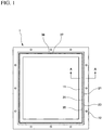
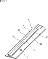
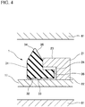
- the gasket 1 includes an attachment plate 11, a side wall part 22, a flange part 23, and a gasket body 31.
- the attachment plate 11 has a frame shape, and is fastened on the flat surface of the car-body- side part (support body) 51.
- the side wall part 22 extends along the peripheral direction of the attachment plate 11.
- the flange part 23 is arranged along the peripheral direction of the side wall part 22. Insertion space 24 is defined between the flange part 23 and the attachment plate 11.
- the gasket body 31 is formed of a rubber-like elastic material by extrusion to have a fixed sectional shape along its entire length.
- the gasket body 31 engages the attachment plate 11 along the entire length of the attachment plate 11 without bonded.
- the gasket body 31 includes an insertion protrusion 36.
- the insertion protrusion 36 is inserted into the insertion space 24.
- the attachment plate 11 is a plate-shaped metal part.
- the attachment plate 11 has a flat rectangular frame shape corresponding to the plan view shape of the battery case 61.
- the attachment plate 11 has screw through holes 12.
- the attachment plate 11 is fastened onto the car-body-side part 51 by screws.
- the screw through holes 12 in this embodiment are arranged on the outer periphery side with respect to a collar 21 and the gasket body 31, they may be arranged on the inner periphery side with respect to the collar 21 and the gasket body 31.
- the side wall part 22 and the flange part 23 are integrally formed to constitute the collar 21.
- the collar 21 is a metal part.
- the collar 21 has a flat rectangular frame shape similar to the attachment plate 11.
- the collar 21 is arranged on the attachment plate 11 along its entire length and fixed to the attachment plate 11 by welding.
- the collar 21 holds the gasket body 31 in place on the flat surface of the attachment plate 11 to reduce a tendency of the gasket body 31 to detach from the attachment plate 11.
- the flange part 23 is integrally formed to extend inward (toward inner periphery side) of the frame shape from the upper end of the side wall part 22. According to this arrangement, the insertion space 24 into which the insertion protrusion 36 is inserted without bonded is defined between the flange part 23 and the attachment plate 11.
- rounded parts which have an arc shape as viewed in a plan view turning roughly right angle may be formed in the corners of the flat rectangular frame shape.
- the gasket body 31 engages the attachment plate 11 and the collar 21 along their entire length without bonded.
- a lower end surface of the gasket body 31 serves as a seal part (first seal part) 32 which is brought in contact with the attachment plate 11.
- Two or more seal beads 33 which have an arc shape as viewed in a cross-sectional view are arranged in the seal part 32 parallel to each other. Stable attachment onto the attachment plate 11 can be provided by the seal beads 33, and as a result the gasket can have good sealing characteristics.
- An upper end surface of the gasket body 31 serves as another seal part (second seal part) 34 which is brought in contact with the battery case 61.
- a seal lip 35 which has a sectionally triangular shape with the same width as the gasket body 31 is arranged in the seal part 34. This seal lip 35 can be easily deformed when the weight of the battery case 61 is put onto the gasket, and as a result the gasket can have good sealing characteristics. All the seal parts 32 and 34, the seal beads 33, and the seal lip 35 extend along the entire length of the gasket body 31.
- the gasket body 31 is an extruded part, and is not endless but has ends.
- the gasket body 31 has ends 37 and 38 on its both ends in the length direction.
- the ends 37 and 38 push each other so that the ends 37 and 38 tightly contact each other.
- the ends 37 and 38 may be bonded to each other by an adhesive or other bonding means.
- the extruded part is not subjected to additional processing which changes a part of the shape of the gasket body 31.
- the insertion protrusion 36 is integrally formed to protrude outward of the frame shape (toward outer periphery side) from a lower end part of the gasket body 31.
- the insertion protrusion 36 is inserted into the insertion space 24 without bonded.
- the insertion protrusion 36 extends along the entire length of the gasket body 31.
- the gasket body 31 which is formed by extrusion as extruded part in the gasket 1 according to this embodiment, is not subjected to additional processing. Also, any gasket attachment groove is not formed by press working in the car-body-side part 51 as a part to which the gasket body 31 is attached. Although the arrangement is simple, the gasket body 31 can be held in place so that the gasket body 31 has a good sealing effect. Therefore, the gasket body 31 has improved workability and attachment characteristics.
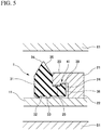
- the insertion protrusion 36 is inserted into the space 24 in the gasket 1 according to the first embodiment, it is not bonded onto the interior surface in the insertion space 24. For this reason, the gasket body 31 may be moved away from a part of the periphery of the collar 21, and the insertion protrusion 36 may be detached from the insertion space 24.
- the gasket 1 includes a gasket stopper structure 41 as shown in Fig. 5 . That is, the flange part 23 includes a first stopper protrusion 25 on its lower surface, and the insertion protrusion 36 includes a second stopper protrusion 39 on its upper surface.
- the stopper protrusions 25 and 39 can interlock with each other, and constitute the gasket stopper structure 41. According to this embodiment, because the stopper protrusions 25 and 39 interlock with each other, detachment of the insertion protrusion 36 from the insertion space 24 can be prevented.
- the side wall part 22 may be integrally formed with the attachment plate 11.
- the flange part 23 is fastened to the side wall part 22.
- Both the side wall part 22 and the flange part 23 may be integrally formed with the attachment plate 11.
- the gasket body 31 may be attached not on the inner periphery side of the side wall part 22 and the flange part 23 (collar 21) but on the outer periphery side.
- the flange part 23 protrudes toward the outer periphery side from the side wall part 22, and the insertion protrusion 36 protrudes toward the inner periphery side from the gasket body 31.
Landscapes
- Engineering & Computer Science (AREA)
- General Engineering & Computer Science (AREA)
- Mechanical Engineering (AREA)
- Physics & Mathematics (AREA)
- Geometry (AREA)
- Gasket Seals (AREA)
Applications Claiming Priority (2)
| Application Number | Priority Date | Filing Date | Title |
|---|---|---|---|
| JP2018208047 | 2018-11-05 | ||
| PCT/JP2019/036877 WO2020095547A1 (ja) | 2018-11-05 | 2019-09-20 | ガスケット |
Publications (1)
| Publication Number | Publication Date |
|---|---|
| EP3879143A1 true EP3879143A1 (de) | 2021-09-15 |
Family
ID=70612363
Family Applications (1)
| Application Number | Title | Priority Date | Filing Date |
|---|---|---|---|
| EP19883033.3A Withdrawn EP3879143A1 (de) | 2018-11-05 | 2019-09-20 | Dichtung |
Country Status (5)
| Country | Link |
|---|---|
| US (1) | US20200408304A1 (de) |
| EP (1) | EP3879143A1 (de) |
| JP (1) | JP6922103B2 (de) |
| CN (1) | CN111566394A (de) |
| WO (1) | WO2020095547A1 (de) |
Families Citing this family (3)
| Publication number | Priority date | Publication date | Assignee | Title |
|---|---|---|---|---|
| US12222036B2 (en) * | 2021-10-08 | 2025-02-11 | Hoffman Enclosures, Inc. | Sealing arrangement for an enclosure |
| DE102023133004B3 (de) * | 2023-11-27 | 2024-12-19 | Endress+Hauser Conducta Gmbh+Co. Kg | Formdichtung, Vorrichtung mit einer Formdichtung, und Verfahren zur Verwendung einer Formdichtung |
| EP4678950A1 (de) * | 2024-07-10 | 2026-01-14 | Carl Freudenberg KG | Dichtelement |
Family Cites Families (7)
| Publication number | Priority date | Publication date | Assignee | Title |
|---|---|---|---|---|
| JP2004108533A (ja) * | 2002-09-20 | 2004-04-08 | Nok Corp | ガスケット |
| JP5093554B2 (ja) * | 2006-06-12 | 2012-12-12 | Nok株式会社 | 燃料電池用ガスケット |
| JP5177690B2 (ja) * | 2009-06-12 | 2013-04-03 | 日本メクトロン株式会社 | 小型電子機器用防水ガスケット |
| JP5474499B2 (ja) * | 2009-11-11 | 2014-04-16 | 三洋電機株式会社 | 車両用の電源装置及びこの電源装置を搭載する車両 |
| JP5760411B2 (ja) | 2010-12-08 | 2015-08-12 | Nok株式会社 | ガスケット |
| JP6014710B1 (ja) * | 2015-04-16 | 2016-10-25 | 櫻護謨株式会社 | シール装置 |
| DE102016213899A1 (de) * | 2016-07-28 | 2018-02-01 | Mahle International Gmbh | Dichtungselement |
-
2019
- 2019-09-20 US US16/962,176 patent/US20200408304A1/en not_active Abandoned
- 2019-09-20 EP EP19883033.3A patent/EP3879143A1/de not_active Withdrawn
- 2019-09-20 WO PCT/JP2019/036877 patent/WO2020095547A1/ja not_active Ceased
- 2019-09-20 CN CN201980007576.1A patent/CN111566394A/zh active Pending
- 2019-09-20 JP JP2020556658A patent/JP6922103B2/ja active Active
Also Published As
| Publication number | Publication date |
|---|---|
| JPWO2020095547A1 (ja) | 2021-02-15 |
| WO2020095547A1 (ja) | 2020-05-14 |
| CN111566394A (zh) | 2020-08-21 |
| JP6922103B2 (ja) | 2021-08-18 |
| US20200408304A1 (en) | 2020-12-31 |
Similar Documents
| Publication | Publication Date | Title |
|---|---|---|
| EP2581631B1 (de) | Dichtung | |
| US20200408304A1 (en) | Gasket | |
| EP3923367A1 (de) | Dichtungsstruktur | |
| EP3923366A1 (de) | Dichtungsstruktur | |
| US7926818B2 (en) | Gasket and structure for sealing between two members | |
| EP3923368A1 (de) | Dichtungsstruktur | |
| JPWO2014080511A1 (ja) | シールワッシャ | |
| KR102532102B1 (ko) | 개스킷 및 그 제조방법 | |
| CN107305988A (zh) | 连接器和带连接器的单元 | |
| EP3141781A1 (de) | Dichtung und abdichtungsstruktur | |
| CN108700196A (zh) | 密封垫和密封装置 | |
| JP2010101490A (ja) | 密封構造 | |
| EP4425041B1 (de) | Leicht zu unterhaltendes wasserdichtes chassis und bühnenlampe damit | |
| US10831051B2 (en) | Display, electronic device and teach pendant for robot | |
| JP2009144765A (ja) | シールパッキン | |
| US11313469B2 (en) | Sealing structure | |
| CN109469730B (zh) | 用于密封的方法和密封设备 | |
| US20060038357A1 (en) | Wedging retainer gasket construction | |
| CN202879389U (zh) | 密封条 | |
| JP5742768B2 (ja) | 車両用ドアのインナパネル構造 | |
| CN110822093A (zh) | 一种硅橡胶密封件 | |
| JP7177195B2 (ja) | ガスケット及び密封装置 | |
| CN110572974A (zh) | 防水结构及led显示屏 | |
| JP7559585B2 (ja) | 照明器具 | |
| JP2015014130A (ja) | 車両用キャリアプレートの取付構造 |
Legal Events
| Date | Code | Title | Description |
|---|---|---|---|
| STAA | Information on the status of an ep patent application or granted ep patent |
Free format text: STATUS: THE INTERNATIONAL PUBLICATION HAS BEEN MADE |
|
| PUAI | Public reference made under article 153(3) epc to a published international application that has entered the european phase |
Free format text: ORIGINAL CODE: 0009012 |
|
| STAA | Information on the status of an ep patent application or granted ep patent |
Free format text: STATUS: REQUEST FOR EXAMINATION WAS MADE |
|
| 17P | Request for examination filed |
Effective date: 20200708 |
|
| AK | Designated contracting states |
Kind code of ref document: A1 Designated state(s): AL AT BE BG CH CY CZ DE DK EE ES FI FR GB GR HR HU IE IS IT LI LT LU LV MC MK MT NL NO PL PT RO RS SE SI SK SM TR |
|
| DAV | Request for validation of the european patent (deleted) | ||
| DAX | Request for extension of the european patent (deleted) | ||
| STAA | Information on the status of an ep patent application or granted ep patent |
Free format text: STATUS: THE APPLICATION HAS BEEN WITHDRAWN |
|
| 18W | Application withdrawn |
Effective date: 20220617 |