EP3879254B1 - Reifenprüfmethode - Google Patents
Reifenprüfmethode Download PDFInfo
- Publication number
- EP3879254B1 EP3879254B1 EP20382185.5A EP20382185A EP3879254B1 EP 3879254 B1 EP3879254 B1 EP 3879254B1 EP 20382185 A EP20382185 A EP 20382185A EP 3879254 B1 EP3879254 B1 EP 3879254B1
- Authority
- EP
- European Patent Office
- Prior art keywords
- tyre
- adjusting
- support
- devices
- frame
- Prior art date
- Legal status (The legal status is an assumption and is not a legal conclusion. Google has not performed a legal analysis and makes no representation as to the accuracy of the status listed.)
- Active
Links
Images




Classifications
-
- B—PERFORMING OPERATIONS; TRANSPORTING
- B60—VEHICLES IN GENERAL
- B60C—VEHICLE TYRES; TYRE INFLATION; TYRE CHANGING; CONNECTING VALVES TO INFLATABLE ELASTIC BODIES IN GENERAL; DEVICES OR ARRANGEMENTS RELATED TO TYRES
- B60C25/00—Apparatus or tools adapted for mounting, removing or inspecting tyres
- B60C25/002—Inspecting tyres
-
- G—PHYSICS
- G01—MEASURING; TESTING
- G01M—TESTING STATIC OR DYNAMIC BALANCE OF MACHINES OR STRUCTURES; TESTING OF STRUCTURES OR APPARATUS, NOT OTHERWISE PROVIDED FOR
- G01M17/00—Testing of vehicles
- G01M17/007—Wheeled or endless-tracked vehicles
- G01M17/02—Tyres
- G01M17/021—Tyre supporting devices, e.g. chucks
-
- G—PHYSICS
- G01—MEASURING; TESTING
- G01M—TESTING STATIC OR DYNAMIC BALANCE OF MACHINES OR STRUCTURES; TESTING OF STRUCTURES OR APPARATUS, NOT OTHERWISE PROVIDED FOR
- G01M17/00—Testing of vehicles
- G01M17/007—Wheeled or endless-tracked vehicles
- G01M17/02—Tyres
- G01M17/022—Tyres the tyre co-operating with rotatable rolls
-
- G—PHYSICS
- G01—MEASURING; TESTING
- G01M—TESTING STATIC OR DYNAMIC BALANCE OF MACHINES OR STRUCTURES; TESTING OF STRUCTURES OR APPARATUS, NOT OTHERWISE PROVIDED FOR
- G01M17/00—Testing of vehicles
- G01M17/007—Wheeled or endless-tracked vehicles
- G01M17/02—Tyres
- G01M17/027—Tyres using light, e.g. infrared, ultraviolet or holographic techniques
Definitions
- the invention tyre support device, relates to a device designed for supporting a tyre and thus enabling the inspection thereof, manually by a user or automated by means of vision systems or devices, enabling the repair thereof, or even enabling trimming or removal of burrs (also manually or automated).
- the device enables the tyre to be arranged in a specific position, after adjusting to the size of the tyre while the same rotates without longitudinal movement, avoiding deformation and reducing vibration.
- the field of application of the present invention falls within the automotive industry sector, specifically focussing on the field of the industry dedicated to the manufacture of apparatuses and devices to carry out tyre manufacturing and/or repairing tasks, and more particularly to tyre inspection tasks, preferably using automated vision systems.
- the tyre In addition to the constitution of the tyres, it must be taken into account that it is necessary to inspect all the surfaces completely, hence the tyre must be handled several times to complete the thorough inspection of the tyre.
- the constitution of the tyre can cause deformations that limit the precision that such automated inspection systems can offer, thereby losing the effectiveness sought by the same and causing human inspection of the tyres to be still necessary.
- tyre sector there are other devices for handling tyres for other purposes, such as tyre repair or removal of burrs after manufacture.
- Document US2011188052A relates to a method of determining geometrical dimensions of a tyre, especially of an inner surface of the tyre and/or a tyre bead, by contact-less sensing, wherein the tyre is received in a receiving means. At least one light beam is emitted onto a peripheral area of the tyre surface, especially on an inner surface of the tyre and/or on a tyre bead, and are evaluated for determining the shape and/or position of the respective impingement area on the tyre.
- the invention relates to an apparatus for determining the geometrical dimensions of a tyre comprising at least one sensing device and a computer-aided evaluation arrangement, wherein the evaluation arrangement is suitable for determining the position of the location sensed by the light beam on the tyre surface from the directions of the emitted light beam and the reflected light beam.
- Prior art document DE202006011739U1 refers to a device that has tires wound on a wheel rim.
- a wheel support has roller cylinders, on which a wheel is displaced in a fixed rolling position in rotation about a rolling axis.
- the wheel support has a wheel bearing for providing a lateral support of the wheel in a rolling position, where the wheel bearing is provided with freely rotatable supporting rollers for the lateral arrangement of the wheel.
- the object of the present invention is a tyre inspection method according to claim 1.
- the support device preferably comprises three adjusting devices on the inclined frame and is supported on a preferably horizontal surface, such that two of the adjusting devices are located on the lower portion of said frame and the third adjusting device is located on the upper surface, all of them concentric to the tyre axis.
- the support device comprises rest or support means for the tyre, which further comprise rotation means that cause the tangential rotation of the tyre on the axis thereof by providing traction on the tyre tread, that is, motorised support and rotation means.
- the device has the three adjusting devices located at 120° from each other, two in the lower portion and one in the upper portion, the three adjusting devices being concentric with respect to the tyre axis.
- the support device comprises only two adjusting devices located in the lower portion of the frame with the support and rotation means, that is, without the upper adjusting device, so that the tyre rests directly on the frame, or on a support element, in said upper area, and because the rotation and support would be done on the lower adjusting devices.
- an upper adjusting device could be provided without resting or support means since said upper adjusting device does not provide traction to the tyre and the main function thereof is to avoid vibrations in the event that they appear.
- an upper adjusting device could be provided with the adjusting means and with the support means but without motorised rotation means.
- the frame of the support device where the adjusting devices rest has an inclined structure with a window, so that the frame has the shape of an inclined frame on a support structure of all the elements of the device.
- the inclination of the frame structure is between 15° and 30°, preferably 20°, with respect to an approximately vertical plane, said approximately vertical plane being preferably perpendicular to the frame support structure and therefore also perpendicular to the surface where said support structure rests, this surface being therefore the one where the whole device rests. That is, the support structure has an inclination of between 60° and 75° with respect to a horizontal surface.
- the axis of the tyre will form 90° with said support structure on which it rests.
- the aforementioned inclination of the support structure enables the swinging of the tyre when it rotates to be prevented, swinging that does occur when the tyre is supported on the tread thereof, at the same time resting on a horizontal surface.
- Each of said lower adjusting devices comprises as support means an shaft or roller where the tyre rests, so that the rotation of said shaft constitutes at the same time the rotation means to rotate the tyre on the axis thereof and at the same time support the tyre that prevents deformation when it rotates, the speed of the tyre preferably being between 10 and 15 rpm.
- the upper adjusting device has, as support means, preferably two shafts or rollers, not motorised and slightly separated from each other, with the aim of preventing the tyre from coming out of the device when applying the corresponding turning speed from the shafts or rollers of the lower adjusting devices.
- the first adjusting means for adjusting to the width, the second adjusting means for adjusting to the diameter, as well as the rotation means of each adjusting device are preferably displaced and/or moved by servo motors.
- the first adjusting means to the width of the tyre comprise a first U-shaped support, with a fixed first end and a second end, parallel to the first end, movable by a servo motor, such that the second end can be adapted to the width of the tyre once the tyre tread is inserted into said U-shaped support.
- the second adjusting means for adjusting to the diameter of the tyre comprise a second support movable over a surface, preferably with one or two rails arranged in turn on the frame of the device or on an extension thereof, for example, on plates or flat sheets on which displacement rails are arranged.
- the first support is arranged on said second support with the first adjusting means for adjusting to the width of the tyre. In this way, the second adjusting means will move the second support along the rail or rails located in the frame and, in turn, will move the first adjusting means that are arranged over the second adjusting means.
- the adjusting means for the diameter are arranged so as to enable the movement of the adjusting means to the width of the tyre along shafts at 120°, maintaining equidistance between the three adjusting devices.
- the intersection point of said shafts is the point where the centre and axis of the tyre must be placed on the device. That is, the rails are arranged so that the first and second adjusting means, and therefore the adjusting devices, move concentrically with respect to the centre of the tyre that is arranged in the support device.
- This concentric movement in the upper adjusting device is preferably vertical.
- the rails on which they move are preferably arranged so that the lower adjusting devices move from one side to the other of the frame, parallel to a horizontal surface, varying the distance between them, while in the case of the upper adjusting device said rails are perpendicular to the previous ones and move from top to bottom.
- the support device object of the invention comprises support means and rotation means as described above.
- Said support and rotation means can correspond to the same means, such that the support means and the rotation means are the same drive shaft or roller, which happens in the lower adjusting devices, where the shaft or roller is arranged preferably on the U-shaped support, between the first end, which is fixed, and the second end, which is movable.
- the upper adjusting device may or may not have these support means and rotation means, it may have the support means but not the rotation means, or it may have both.
- the upper adjusting device has two shafts or rollers as support means.
- the device object of the invention can also incorporate, to facilitate access to the interior of the tyre, specifically to the interior of the tyre tread, as well as to the interior of the sides, a mechanism for opening the tyre that is integrated in the lower adjusting devices.
- Said mechanism preferably pneumatic, has claws that are inserted in the interior of the tyre from the side thereof and that when opened cause the separation of the sides of the tyre, thus facilitating access to the interior thereof, both to the interior of the tyre tread and to the interior of the sides.
- Said claws have rollers or cylinders at their ends that enable the tyre to rotate.
- the mechanical elements to achieve the movements and adjustments of the previous devices and means may vary, as well as the components that make them up.
- the tyre support device according to the claimed invention works as follows:
- the device includes a tyre opening mechanism, it will act before activating the rotation of the shafts or rollers of the lower adjusting devices.
- the device object of the invention is preferably used for automated tyre inspection, so it will be necessary to have vision systems or display elements, usually cameras and profilometers, to be able to inspect all parts of the tyre, namely:
- the vision systems will be installed, as far as possible, in the tyre support device itself and when this is not possible because either the handling of the tyre prevents it or the required angle of inclination of the vision system requires it, any necessary means will be used, mainly robotic arms that incorporate said vision systems at their ends.
- the systems for viewing the outer side of the tyre tread, as well as the outer side of the sides are arranged on the upper fixing device, in frames arranged for this purpose.
- Such frames could be arranged elsewhere as long as they do not interfere with the operation of the device components.
- vision systems are inserted through the hole of the tyre to access the interior of the tyre tread and the interior of the sides. Access to the interior can be done both from one side of the frame and from the opposite side through the hollow or window made in it.
- the support device comprises an inclined frame (10), which can be arranged on a support structure (not shown), preferably supported on a horizontal surface, with
- the frame (10) has an inclined structure with a central window or hollow (11), preferably in the shape of a housing, the inclination of the structure preferably being close to 20°, between 15° and 30°, with respect to a perpendicular to a supporting horizontal surface.
- the three adjusting devices (50, 60, 70) are arranged, the two lower adjusting devices (50, 60) having first adjusting means for adjusting to the width (3), second adjusting means for adjusting to the diameter (4) of the tyre and support means (5) of the tyre that coincide with the motorised rotation means of the tyre on the axis thereof, specifically rollers or cylinders (5).
- the upper adjusting device (70) preferably further has adjusting means (3, 4) as well as the above support means (5) present in the two lower adjusting devices (50, 60), although preferably it does not have any motorised rotation means, such that the support means (5) of the upper adjusting device (70) rotate due to the traction transmitted by the rotating tyre itself due to the action of the motorised rotation means (5) of the lower adjusting devices (50, 60).
- the support device object of the invention may not have (not shown) any upper adjusting device (70), such that the tyre would rest directly on the upper portion of the frame (10) or on a roller or rollers arranged for this purpose on the frame (10).
- Each of the lower adjusting devices (50, 60) comprises, as support means (5) and rotation means, an shaft, roller or cylinder (5) that performs said support and rotation of the tyre functions, said shaft, roller or cylinder (5) being motorised to be able to transmit that rotation to the tyre.
- Said shaft, roller or cylinder (5) is perpendicular to the frame (10) and constitutes the means for supporting and rotating the tyre on the very axis thereof since the tyre rests on said support and rotation shafts or rollers (5) of the lower adjusting devices (50, 60).
- the upper adjusting device (70) if the same does not exhibit rotation means, it is possible that it exhibits at least one shaft, roller or cylinder, as support means (5), which will also rotate dragged by the tyre.
- the shafts, rollers or cylinders of the support means (5) of the adjusting devices (50, 60, 70) are parallel to each other.
- said three adjusting devices (50, 60, 70) are incorporated into said frame (10) arranged in such a way that the two lower adjusting devices (50, 60) are located in the lower portion of the frame, (10) with their support and rotation shafts (5) separated and horizontally movable, and the upper adjusting device (70) is arranged on the upper portion of the frame (10) equidistant, at all times, to both lower adjusting devices (50, 60).
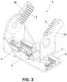
- Figure 2 shows the first adjusting means for adjusting to the width (3) which includes each adjusting device (50, 60, 70) and which are preferably determined by a U-shaped structure formed by two arms, one fixed (30) and one movable (31) (although they could be both movable), said structure moving on a runner (7) associated with a servomotor (6) and inserted into a rail (8) of a base plate (9), such that the movable arm (31) moves closer and further away from the fixed arm (30) to adjust to the width of the tyre.
- each arm (30, 31) the incorporation of a series of bearings (2) is envisaged, which are attached to the lateral surface of the tyre, rolling with it when turning it so as not to cause friction.
- the second adjusting means for adjusting to the diameter (4), shown in Figure 3 , of the adjusting devices (50, 60, 70) comprise a support plate (40) which, integrally attached to the frame (10) of the support device, is provided with rails (8) on which runners (7) run, associated with a servomotor (6), and on which a movable plate (41) is fixed on which, in turn, the U-shaped arms structure (30, 31) of the first adjusting means (3) is coupled with the corresponding support and rotation shaft (5) of the support means (5), to move said movable plate (41) from one end to the other of said support plate (40) and adjust the position thereof to the diameter of the tyre.
- Figure 3 shows how said second adjusting means for adjusting to the diameter (4), for the upper adjusting device (70), exhibit a vertical displacement movement of the movable plate (41), the support and rotation shaft (5), which rotates freely, being fastened directly to said plate (41), there being in said plate (41) spacers (42) on which the U-shaped arms structure (30, 31) of the first adjusting means (3) rests.
- the movable plate (41) exhibits a horizontal displacement movement, the support and rotation shafts (5) being drive rollers or cylinders.
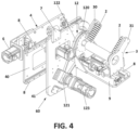
- the rotation system of said rollers 5 can be made up of a servo motor (123) associated with a belt (122) associated with a planetary gear reduction system (12) formed by a rotating plate (120) and a pinion (121), in order to transmit the movement from the servomotor (123) to the roller (5).
- Other systems could also be used.
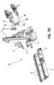
- FIGS 5 to 8 show a second exemplary embodiment of the invention.
- This second example shows a tyre support device (N) comprising an inclined frame (10) with a window or hollow (11) and arranged on a support structure (12).
- Said support device comprises:
- the adjusting devices (50, 60, 70) are arranged, as mentioned, on adjusting means for adjusting to the diameter (4) that serve to adjust the devices to the diameter of the tyre and stabilise the tyre, such that they move in parallel to axes at 120° that intersect at a point located on the axis (n) of the tyre arranged on the support device (10) object of the invention.
- this second example has an opening mechanism (80) of the tyre integrated in each of the lower adjusting devices (50, 60).
- This mechanism (80) which could also be integrated in the first exemplary embodiment, aims to facilitate access to the interior of the tyre, specifically to the interior of the tyre tread, as well as to the interior of the sides.
- Said mechanism (80) preferably actuated by pneumatic means, has claws (81) that are inserted inside the tyre (N) through the side thereof and when opened cause the separation of the sides of the tyre (N), thus facilitating access to the interior of the same, both to the interior of the tyre tread and the interior of the sides.
- Said claws (81) have at the ends thereof rollers or cylinders (82) that enable the tyre to rotate when the support and rotation means (5) arranged in the lower adjusting devices (50, 60) cause the rotation of the whole tyre.
- the adjusting means for adjusting to the diameter (4) of the three adjusting devices move, as mentioned, radially with respect to the centre of the tyre, each device maintaining equidistance with respect to the others as they approach or move away from the centre of the tyre depending on the dimensions of the tyre.
- the adjusting means to the width (3) also move on said adjusting means to the diameter.
- Said adjusting means to the width (3) have a configuration similar to that described for the first exemplary embodiment, wherein a first movable arm moves with respect to a second fixed arm, both arms being parallel and having bearings to facilitate the rotation of the tyre.
- the tyre rests on two arranged shafts, rollers or cylinders that form the support means (5), said support means being motorised and activated by servomotors (123) in the case of the lower adjusting devices (50, 60).
- the support means (5) are not motorised, but have a double support system formed by two rollers that are distanced from each other, acting as a stop and preventing the tyre from coming out of the support device as a result of rotation.
- This second example further shows how the upper adjusting device (70) integrates vision systems (90) formed by a camera or profilometer and a laser.
- vision systems 90
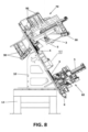
- FIG 8 although they are also seen in figures 5 and 6 , there are several vision devices or systems (90), two located in the upper portion to capture and record the tyre tread and two others located on each side of the tyre, capturing the sides thereof.
- the side of the tyre located on the side of the support device (10) is inspected by a vision system (90) that accesses said side through the window or hollow (11) of the frame (10).
- the light beams emitted by the necessary laser devices are observed so that the cameras or profilometers capture the surface with sufficient resolution.
Landscapes
- Physics & Mathematics (AREA)
- General Physics & Mathematics (AREA)
- Engineering & Computer Science (AREA)
- Mechanical Engineering (AREA)
- Tyre Moulding (AREA)
- Automobile Manufacture Line, Endless Track Vehicle, Trailer (AREA)
- Testing Of Balance (AREA)
- Investigating Materials By The Use Of Optical Means Adapted For Particular Applications (AREA)
- Vehicle Body Suspensions (AREA)
- Heating, Cooling, Or Curing Plastics Or The Like In General (AREA)
Claims (1)
- Ein automatisiertes Reifenprüfverfahren, dadurch gekennzeichnet, dass es die folgenden Schritte umfasst- Platzieren eines Reifens (N) auf einer Reifenstützvorrichtung, die einen Rahmen mit einer geneigten Struktur (10) mit einem Fenster (11) umfasst, Auflegen einer Seite des Reifens (N) auf die Struktur (10), Vorsehen von mindestens zwei Einstellvorrichtungen an dem Rahmen zum Positionieren des Reifens (N) auf dem Rahmen, wobei jede der Einstellvorrichtungen ferner umfasst:∘ zweite Einstellmittel (4), die sich auf der geneigten Struktur (10) des Rahmens bewegen, zum Anpassen an den Durchmesser des Reifens (N),∘ erste Einstellmittel (3), die auf den zweiten Einstellmitteln (4) angeordnet sind, um sich entlang derselben zu verschieben, um sich an die Breite des Reifens (N) anzupassen, und∘ Stützmittel (5), die mit den ersten Einstellmitteln (3) verbunden sind, um den Reifen (N) auf seiner Lauffläche zu stützen, die durch Drehmittel angetrieben werden, die die Stützmittel (5) in Drehung versetzen, um den Reifen (N) um seine Achse zu drehen,- Bewegen der zweiten Einstellmittel (4) von jeder der Einstellvorrichtungen, um sie an den Durchmesser des Reifens (N) anzupassen,- Bewegen der ersten Einstellmittel (3), bis sie an die Breite des Reifens (N) angepasst sind, und- Drehen der Stützmittel (5), um den Reifen (N) zum Drehen zu zwingen, und- Prüfen der Teile des Reifens (N) mit Sichtsystemen oder Anzeigeelementen.
Priority Applications (21)
| Application Number | Priority Date | Filing Date | Title |
|---|---|---|---|
| HUE20382185A HUE068928T2 (hu) | 2020-03-12 | 2020-03-12 | Gumiabroncs-vizsgáló eljárás |
| EP20382185.5A EP3879254B1 (de) | 2020-03-12 | 2020-03-12 | Reifenprüfmethode |
| ES20382185T ES2994169T3 (en) | 2020-03-12 | 2020-03-12 | Tyre inspection method |
| PL20382185.5T PL3879254T3 (pl) | 2020-03-12 | 2020-03-12 | Sposób kontroli opon |
| PT208453985T PT4095507T (pt) | 2020-03-12 | 2020-12-29 | Dispositivo de suporte de pneu |
| BR112022017929A BR112022017929A2 (pt) | 2020-03-12 | 2020-12-29 | Dispositivo de suporte de pneus |
| KR1020227035078A KR102808995B1 (ko) | 2020-03-12 | 2020-12-29 | 타이어 지지 장치 |
| CA3170935A CA3170935C (en) | 2020-03-12 | 2020-12-29 | Method for automated tyre inspection using a tyre support device |
| US17/910,644 US12594795B2 (en) | 2020-03-12 | 2020-12-29 | Tyre support device |
| ES20845398T ES2961977T3 (es) | 2020-03-12 | 2020-12-29 | Dispositivo de soporte de neumáticos |
| RS20231086A RS64868B1 (sr) | 2020-03-12 | 2020-12-29 | Potporni uređaj za gumu |
| HUE20845398A HUE064413T2 (hu) | 2020-03-12 | 2020-12-29 | Gumiabroncstartó eszköz |
| JP2022555107A JP7595081B2 (ja) | 2020-03-12 | 2020-12-29 | タイヤ支持装置 |
| PL20845398.5T PL4095507T3 (pl) | 2020-03-12 | 2020-12-29 | Urządzenie do podpierania opony |
| AU2020435660A AU2020435660B2 (en) | 2020-03-12 | 2020-12-29 | Tyre support device |
| EP20845398.5A EP4095507B1 (de) | 2020-03-12 | 2020-12-29 | Reifenstützvorrichtung |
| CR20220455A CR20220455A (es) | 2020-03-12 | 2020-12-29 | Dispositivo de soporte de neumaticos |
| PCT/ES2020/070825 WO2021180986A1 (es) | 2020-03-12 | 2020-12-29 | Dispositivo de soporte de neumaticos |
| EP23187430.6A EP4239309B1 (de) | 2020-03-12 | 2020-12-29 | Reifenprüfverfahren |
| MX2022011264A MX2022011264A (es) | 2020-03-12 | 2020-12-29 | Dispositivo de soporte de neumaticos. |
| CN202080098375.XA CN115280126B (zh) | 2020-03-12 | 2020-12-29 | 轮胎支撑设备 |
Applications Claiming Priority (1)
| Application Number | Priority Date | Filing Date | Title |
|---|---|---|---|
| EP20382185.5A EP3879254B1 (de) | 2020-03-12 | 2020-03-12 | Reifenprüfmethode |
Publications (3)
| Publication Number | Publication Date |
|---|---|
| EP3879254A1 EP3879254A1 (de) | 2021-09-15 |
| EP3879254B1 true EP3879254B1 (de) | 2024-09-11 |
| EP3879254C0 EP3879254C0 (de) | 2024-09-11 |
Family
ID=70108143
Family Applications (3)
| Application Number | Title | Priority Date | Filing Date |
|---|---|---|---|
| EP20382185.5A Active EP3879254B1 (de) | 2020-03-12 | 2020-03-12 | Reifenprüfmethode |
| EP20845398.5A Active EP4095507B1 (de) | 2020-03-12 | 2020-12-29 | Reifenstützvorrichtung |
| EP23187430.6A Active EP4239309B1 (de) | 2020-03-12 | 2020-12-29 | Reifenprüfverfahren |
Family Applications After (2)
| Application Number | Title | Priority Date | Filing Date |
|---|---|---|---|
| EP20845398.5A Active EP4095507B1 (de) | 2020-03-12 | 2020-12-29 | Reifenstützvorrichtung |
| EP23187430.6A Active EP4239309B1 (de) | 2020-03-12 | 2020-12-29 | Reifenprüfverfahren |
Country Status (15)
| Country | Link |
|---|---|
| US (1) | US12594795B2 (de) |
| EP (3) | EP3879254B1 (de) |
| JP (1) | JP7595081B2 (de) |
| KR (1) | KR102808995B1 (de) |
| CN (1) | CN115280126B (de) |
| AU (1) | AU2020435660B2 (de) |
| BR (1) | BR112022017929A2 (de) |
| CR (1) | CR20220455A (de) |
| ES (2) | ES2994169T3 (de) |
| HU (2) | HUE068928T2 (de) |
| MX (1) | MX2022011264A (de) |
| PL (2) | PL3879254T3 (de) |
| PT (1) | PT4095507T (de) |
| RS (1) | RS64868B1 (de) |
| WO (1) | WO2021180986A1 (de) |
Family Cites Families (24)
| Publication number | Priority date | Publication date | Assignee | Title |
|---|---|---|---|---|
| GB887321A (en) * | 1957-03-13 | 1962-01-17 | Yates Plant Ltd | Improvements in roller apparatus for supporting and rotating cylindrical objects |
| US3843000A (en) * | 1973-06-08 | 1974-10-22 | V Bennett | Painters wheel spinner |
| US3937343A (en) * | 1973-11-09 | 1976-02-10 | Reynold Spulak | Adjustable tire cart |
| US4293120A (en) * | 1980-03-03 | 1981-10-06 | Robins Robert R | Tire holder and bead expander |
| IT1243660B (it) * | 1990-10-22 | 1994-06-16 | Corghi Spa | Macchina smontagomme con autrocentrante reclinabile. |
| US6269689B1 (en) * | 1998-07-22 | 2001-08-07 | Oliver Rubber Company | Tire inspection equipment and method |
| JP2001235384A (ja) | 1999-12-14 | 2001-08-31 | Honda Motor Co Ltd | ホィール付タイヤの回転装置 |
| DE20314939U1 (de) * | 2003-09-30 | 2003-12-11 | Dengler, Stefan | Reifenprüfeinrichtung mit hängendem Reifen |
| US7699087B2 (en) * | 2005-06-29 | 2010-04-20 | Schenck Rotec Gmbh | Method for mounting a pneumatic tire |
| JP2007047089A (ja) | 2005-08-11 | 2007-02-22 | Bridgestone Corp | 空気のう外観検査装置及び空気のう外見検査方法 |
| DE202006011739U1 (de) * | 2006-07-28 | 2007-12-06 | 4 Wheels Service + Logistik Gmbh | Radkontrolleinrichtung |
| KR101141711B1 (ko) * | 2006-08-09 | 2012-05-04 | 삼성테크윈 주식회사 | 테이프 배출장치 및 테이프 배출방법 |
| JP5445738B2 (ja) | 2009-03-09 | 2014-03-19 | 横浜ゴム株式会社 | タイヤ撮影用補助装置 |
| JP5477550B2 (ja) * | 2009-08-11 | 2014-04-23 | 横浜ゴム株式会社 | タイヤ外観検査用補助装置 |
| JP2011143687A (ja) * | 2010-01-18 | 2011-07-28 | Bridgestone Corp | タイヤ製造装置 |
| EP2353890A1 (de) * | 2010-01-29 | 2011-08-10 | Snap-on Equipment Srl a unico socio | Vorrichtung und Verfahren zur Bestimmung geometrischer Abmessungen eines Reifens mittels optischer Sensoren |
| DE102010017031A1 (de) * | 2010-05-19 | 2011-11-24 | Schenck Rotec Gmbh | Vorrichtung und Verfahren zur Änderung der Drehwinkellage eines Luftreifens auf einer Felge |
| US8973639B2 (en) * | 2011-12-29 | 2015-03-10 | Android Industries Llc | System and method for processing a tire-wheel assembly |
| KR101708853B1 (ko) * | 2015-08-17 | 2017-02-21 | 선운(주) | 타이어 펑크 점검장치 |
| CN106733330A (zh) * | 2017-01-04 | 2017-05-31 | 卢文哲 | 一种轮胎喷胶机的轮胎定位装置 |
| CN207171676U (zh) * | 2017-08-25 | 2018-04-03 | 苏州鑫敬轩机电科技有限公司 | 轮胎内壁浮动打磨装置 |
| CN108501632A (zh) * | 2018-04-10 | 2018-09-07 | 孙涛 | 一种雪地快装防滑履带 |
| CN108534705B (zh) * | 2018-06-25 | 2020-11-24 | 嘉兴量创科技有限公司 | 一种自动轮胎花纹深度测量检测方法 |
| CN110316284B (zh) * | 2019-06-06 | 2021-11-23 | 聊城市洛溪信息科技有限公司 | 一种汽车轮胎一体化自动装配设备 |
-
2020
- 2020-03-12 HU HUE20382185A patent/HUE068928T2/hu unknown
- 2020-03-12 ES ES20382185T patent/ES2994169T3/es active Active
- 2020-03-12 PL PL20382185.5T patent/PL3879254T3/pl unknown
- 2020-03-12 EP EP20382185.5A patent/EP3879254B1/de active Active
- 2020-12-29 CR CR20220455A patent/CR20220455A/es unknown
- 2020-12-29 JP JP2022555107A patent/JP7595081B2/ja active Active
- 2020-12-29 WO PCT/ES2020/070825 patent/WO2021180986A1/es not_active Ceased
- 2020-12-29 PL PL20845398.5T patent/PL4095507T3/pl unknown
- 2020-12-29 ES ES20845398T patent/ES2961977T3/es active Active
- 2020-12-29 AU AU2020435660A patent/AU2020435660B2/en active Active
- 2020-12-29 BR BR112022017929A patent/BR112022017929A2/pt unknown
- 2020-12-29 RS RS20231086A patent/RS64868B1/sr unknown
- 2020-12-29 KR KR1020227035078A patent/KR102808995B1/ko active Active
- 2020-12-29 EP EP20845398.5A patent/EP4095507B1/de active Active
- 2020-12-29 US US17/910,644 patent/US12594795B2/en active Active
- 2020-12-29 CN CN202080098375.XA patent/CN115280126B/zh active Active
- 2020-12-29 HU HUE20845398A patent/HUE064413T2/hu unknown
- 2020-12-29 EP EP23187430.6A patent/EP4239309B1/de active Active
- 2020-12-29 PT PT208453985T patent/PT4095507T/pt unknown
- 2020-12-29 MX MX2022011264A patent/MX2022011264A/es unknown
Also Published As
| Publication number | Publication date |
|---|---|
| CN115280126A (zh) | 2022-11-01 |
| JP2023525438A (ja) | 2023-06-16 |
| EP4239309C0 (de) | 2026-02-18 |
| PL4095507T3 (pl) | 2024-02-19 |
| EP3879254C0 (de) | 2024-09-11 |
| HUE064413T2 (hu) | 2024-03-28 |
| PT4095507T (pt) | 2023-11-09 |
| EP4239309A1 (de) | 2023-09-06 |
| US12594795B2 (en) | 2026-04-07 |
| CR20220455A (es) | 2023-06-23 |
| WO2021180986A1 (es) | 2021-09-16 |
| EP4095507A1 (de) | 2022-11-30 |
| EP4239309B1 (de) | 2026-02-18 |
| MX2022011264A (es) | 2022-10-07 |
| RS64868B1 (sr) | 2023-12-29 |
| AU2020435660A1 (en) | 2022-09-22 |
| EP3879254A1 (de) | 2021-09-15 |
| KR102808995B1 (ko) | 2025-05-15 |
| HUE068928T2 (hu) | 2025-02-28 |
| AU2020435660B2 (en) | 2026-01-22 |
| EP4095507B1 (de) | 2023-09-27 |
| KR20220150969A (ko) | 2022-11-11 |
| BR112022017929A2 (pt) | 2022-10-18 |
| US20230150318A1 (en) | 2023-05-18 |
| ES2994169T3 (en) | 2025-01-20 |
| JP7595081B2 (ja) | 2024-12-05 |
| ES2961977T3 (es) | 2024-03-14 |
| CN115280126B (zh) | 2025-09-19 |
| PL3879254T3 (pl) | 2025-02-24 |
| CA3170935A1 (en) | 2021-09-16 |
Similar Documents
| Publication | Publication Date | Title |
|---|---|---|
| US11597091B2 (en) | Robotic target alignment for vehicle sensor calibration | |
| US11835646B2 (en) | Target alignment for vehicle sensor calibration | |
| KR102833769B1 (ko) | 차량 센서 보정을 위한 로봇 타겟 정렬 | |
| EP4100725B1 (de) | Systeme und verfahren zur rundum-inspektion eines objektes | |
| KR102195817B1 (ko) | 기판 반송 장치 | |
| US20050188755A1 (en) | Tire positioning sensor | |
| JP3148677B2 (ja) | タイヤとホイールの位相合わせ装置及びその制御方法 | |
| EP4239309B1 (de) | Reifenprüfverfahren | |
| CA3170935C (en) | Method for automated tyre inspection using a tyre support device | |
| JP7750943B2 (ja) | 装備済み車両上のセンサの校正のために装備済み車両にターゲットを位置合わせするためのシステム及び装備済み車両上のセンサの校正のために装備済み車両に対してターゲットを位置合わせする方法 | |
| JP4889381B2 (ja) | 支持リムへのタイヤの芯合わせ方法および装置 | |
| RU2817154C1 (ru) | Опорное устройство для шины | |
| CN118688210B (zh) | 焊接检测系统及焊接检测方法 | |
| JP2000126825A (ja) | スピニング製造方法 | |
| CN121925549A (zh) | 车辆传感器校准与测试系统 | |
| HK40089180A (zh) | 用於车辆传感器校准的目标对准 |
Legal Events
| Date | Code | Title | Description |
|---|---|---|---|
| PUAI | Public reference made under article 153(3) epc to a published international application that has entered the european phase |
Free format text: ORIGINAL CODE: 0009012 |
|
| STAA | Information on the status of an ep patent application or granted ep patent |
Free format text: STATUS: THE APPLICATION HAS BEEN PUBLISHED |
|
| AK | Designated contracting states |
Kind code of ref document: A1 Designated state(s): AL AT BE BG CH CY CZ DE DK EE ES FI FR GB GR HR HU IE IS IT LI LT LU LV MC MK MT NL NO PL PT RO RS SE SI SK SM TR |
|
| STAA | Information on the status of an ep patent application or granted ep patent |
Free format text: STATUS: REQUEST FOR EXAMINATION WAS MADE |
|
| 17P | Request for examination filed |
Effective date: 20220314 |
|
| RBV | Designated contracting states (corrected) |
Designated state(s): AL AT BE BG CH CY CZ DE DK EE ES FI FR GB GR HR HU IE IS IT LI LT LU LV MC MK MT NL NO PL PT RO RS SE SI SK SM TR |
|
| RAP1 | Party data changed (applicant data changed or rights of an application transferred) |
Owner name: METADATIA TECHNOLOGIES S.L. |
|
| STAA | Information on the status of an ep patent application or granted ep patent |
Free format text: STATUS: EXAMINATION IS IN PROGRESS |
|
| 17Q | First examination report despatched |
Effective date: 20230718 |
|
| RAP1 | Party data changed (applicant data changed or rights of an application transferred) |
Owner name: VRAIA CORP, S.L. |
|
| GRAP | Despatch of communication of intention to grant a patent |
Free format text: ORIGINAL CODE: EPIDOSNIGR1 |
|
| STAA | Information on the status of an ep patent application or granted ep patent |
Free format text: STATUS: GRANT OF PATENT IS INTENDED |
|
| INTG | Intention to grant announced |
Effective date: 20240506 |
|
| GRAS | Grant fee paid |
Free format text: ORIGINAL CODE: EPIDOSNIGR3 |
|
| GRAA | (expected) grant |
Free format text: ORIGINAL CODE: 0009210 |
|
| STAA | Information on the status of an ep patent application or granted ep patent |
Free format text: STATUS: THE PATENT HAS BEEN GRANTED |
|
| AK | Designated contracting states |
Kind code of ref document: B1 Designated state(s): AL AT BE BG CH CY CZ DE DK EE ES FI FR GB GR HR HU IE IS IT LI LT LU LV MC MK MT NL NO PL PT RO RS SE SI SK SM TR |
|
| REG | Reference to a national code |
Ref country code: GB Ref legal event code: FG4D |
|
| REG | Reference to a national code |
Ref country code: CH Ref legal event code: EP |
|
| REG | Reference to a national code |
Ref country code: DE Ref legal event code: R096 Ref document number: 602020037476 Country of ref document: DE |
|
| REG | Reference to a national code |
Ref country code: IE Ref legal event code: FG4D |
|
| U01 | Request for unitary effect filed |
Effective date: 20241010 |
|
| U07 | Unitary effect registered |
Designated state(s): AT BE BG DE DK EE FI FR IT LT LU LV MT NL PT RO SE SI Effective date: 20241029 |
|
| PG25 | Lapsed in a contracting state [announced via postgrant information from national office to epo] |
Ref country code: NO Free format text: LAPSE BECAUSE OF FAILURE TO SUBMIT A TRANSLATION OF THE DESCRIPTION OR TO PAY THE FEE WITHIN THE PRESCRIBED TIME-LIMIT Effective date: 20241211 |
|
| PG25 | Lapsed in a contracting state [announced via postgrant information from national office to epo] |
Ref country code: GR Free format text: LAPSE BECAUSE OF FAILURE TO SUBMIT A TRANSLATION OF THE DESCRIPTION OR TO PAY THE FEE WITHIN THE PRESCRIBED TIME-LIMIT Effective date: 20241212 |
|
| REG | Reference to a national code |
Ref country code: ES Ref legal event code: FG2A Ref document number: 2994169 Country of ref document: ES Kind code of ref document: T3 Effective date: 20250120 |
|
| PG25 | Lapsed in a contracting state [announced via postgrant information from national office to epo] |
Ref country code: HR Free format text: LAPSE BECAUSE OF FAILURE TO SUBMIT A TRANSLATION OF THE DESCRIPTION OR TO PAY THE FEE WITHIN THE PRESCRIBED TIME-LIMIT Effective date: 20240911 |
|
| PG25 | Lapsed in a contracting state [announced via postgrant information from national office to epo] |
Ref country code: RS Free format text: LAPSE BECAUSE OF FAILURE TO SUBMIT A TRANSLATION OF THE DESCRIPTION OR TO PAY THE FEE WITHIN THE PRESCRIBED TIME-LIMIT Effective date: 20241211 |
|
| PG25 | Lapsed in a contracting state [announced via postgrant information from national office to epo] |
Ref country code: RS Free format text: LAPSE BECAUSE OF FAILURE TO SUBMIT A TRANSLATION OF THE DESCRIPTION OR TO PAY THE FEE WITHIN THE PRESCRIBED TIME-LIMIT Effective date: 20241211 Ref country code: NO Free format text: LAPSE BECAUSE OF FAILURE TO SUBMIT A TRANSLATION OF THE DESCRIPTION OR TO PAY THE FEE WITHIN THE PRESCRIBED TIME-LIMIT Effective date: 20241211 Ref country code: HR Free format text: LAPSE BECAUSE OF FAILURE TO SUBMIT A TRANSLATION OF THE DESCRIPTION OR TO PAY THE FEE WITHIN THE PRESCRIBED TIME-LIMIT Effective date: 20240911 Ref country code: GR Free format text: LAPSE BECAUSE OF FAILURE TO SUBMIT A TRANSLATION OF THE DESCRIPTION OR TO PAY THE FEE WITHIN THE PRESCRIBED TIME-LIMIT Effective date: 20241212 |
|
| REG | Reference to a national code |
Ref country code: HU Ref legal event code: AG4A Ref document number: E068928 Country of ref document: HU |
|
| U20 | Renewal fee for the european patent with unitary effect paid |
Year of fee payment: 6 Effective date: 20250211 |
|
| PG25 | Lapsed in a contracting state [announced via postgrant information from national office to epo] |
Ref country code: IS Free format text: LAPSE BECAUSE OF FAILURE TO SUBMIT A TRANSLATION OF THE DESCRIPTION OR TO PAY THE FEE WITHIN THE PRESCRIBED TIME-LIMIT Effective date: 20250111 |
|
| PG25 | Lapsed in a contracting state [announced via postgrant information from national office to epo] |
Ref country code: SM Free format text: LAPSE BECAUSE OF FAILURE TO SUBMIT A TRANSLATION OF THE DESCRIPTION OR TO PAY THE FEE WITHIN THE PRESCRIBED TIME-LIMIT Effective date: 20240911 |
|
| PG25 | Lapsed in a contracting state [announced via postgrant information from national office to epo] |
Ref country code: CZ Free format text: LAPSE BECAUSE OF FAILURE TO SUBMIT A TRANSLATION OF THE DESCRIPTION OR TO PAY THE FEE WITHIN THE PRESCRIBED TIME-LIMIT Effective date: 20240911 |
|
| PG25 | Lapsed in a contracting state [announced via postgrant information from national office to epo] |
Ref country code: SK Free format text: LAPSE BECAUSE OF FAILURE TO SUBMIT A TRANSLATION OF THE DESCRIPTION OR TO PAY THE FEE WITHIN THE PRESCRIBED TIME-LIMIT Effective date: 20240911 |
|
| PGFP | Annual fee paid to national office [announced via postgrant information from national office to epo] |
Ref country code: ES Payment date: 20250401 Year of fee payment: 6 |
|
| PLBE | No opposition filed within time limit |
Free format text: ORIGINAL CODE: 0009261 |
|
| STAA | Information on the status of an ep patent application or granted ep patent |
Free format text: STATUS: NO OPPOSITION FILED WITHIN TIME LIMIT |
|
| 26N | No opposition filed |
Effective date: 20250612 |
|
| PG25 | Lapsed in a contracting state [announced via postgrant information from national office to epo] |
Ref country code: MC Free format text: LAPSE BECAUSE OF FAILURE TO SUBMIT A TRANSLATION OF THE DESCRIPTION OR TO PAY THE FEE WITHIN THE PRESCRIBED TIME-LIMIT Effective date: 20240911 |
|
| REG | Reference to a national code |
Ref country code: CH Ref legal event code: H13 Free format text: ST27 STATUS EVENT CODE: U-0-0-H10-H13 (AS PROVIDED BY THE NATIONAL OFFICE) Effective date: 20251023 |
|
| PG25 | Lapsed in a contracting state [announced via postgrant information from national office to epo] |
Ref country code: CH Free format text: LAPSE BECAUSE OF NON-PAYMENT OF DUE FEES Effective date: 20250331 |
|
| PG25 | Lapsed in a contracting state [announced via postgrant information from national office to epo] |
Ref country code: IE Free format text: LAPSE BECAUSE OF NON-PAYMENT OF DUE FEES Effective date: 20250312 |
|
| U20 | Renewal fee for the european patent with unitary effect paid |
Year of fee payment: 7 Effective date: 20260123 |
|
| PGFP | Annual fee paid to national office [announced via postgrant information from national office to epo] |
Ref country code: GB Payment date: 20260127 Year of fee payment: 7 |
|
| PGFP | Annual fee paid to national office [announced via postgrant information from national office to epo] |
Ref country code: HU Payment date: 20260323 Year of fee payment: 7 |
|
| PGFP | Annual fee paid to national office [announced via postgrant information from national office to epo] |
Ref country code: TR Payment date: 20260304 Year of fee payment: 7 |
|
| PGFP | Annual fee paid to national office [announced via postgrant information from national office to epo] |
Ref country code: PL Payment date: 20260225 Year of fee payment: 7 |