EP3879611A1 - Matériau composite ayant une structure ceur-enveloppe pour batterie, batterie secondaire, module de batterie, bloc-batterie et appareil - Google Patents
Matériau composite ayant une structure ceur-enveloppe pour batterie, batterie secondaire, module de batterie, bloc-batterie et appareil Download PDFInfo
- Publication number
- EP3879611A1 EP3879611A1 EP20892294.8A EP20892294A EP3879611A1 EP 3879611 A1 EP3879611 A1 EP 3879611A1 EP 20892294 A EP20892294 A EP 20892294A EP 3879611 A1 EP3879611 A1 EP 3879611A1
- Authority
- EP
- European Patent Office
- Prior art keywords
- composite material
- optionally
- battery
- secondary battery
- copper
- Prior art date
- Legal status (The legal status is an assumption and is not a legal conclusion. Google has not performed a legal analysis and makes no representation as to the accuracy of the status listed.)
- Granted
Links
Images


Classifications
-
- H—ELECTRICITY
- H01—ELECTRIC ELEMENTS
- H01M—PROCESSES OR MEANS, e.g. BATTERIES, FOR THE DIRECT CONVERSION OF CHEMICAL ENERGY INTO ELECTRICAL ENERGY
- H01M10/00—Secondary cells; Manufacture thereof
- H01M10/42—Methods or arrangements for servicing or maintenance of secondary cells or secondary half-cells
- H01M10/4235—Safety or regulating additives or arrangements in electrodes, separators or electrolyte
-
- H—ELECTRICITY
- H01—ELECTRIC ELEMENTS
- H01M—PROCESSES OR MEANS, e.g. BATTERIES, FOR THE DIRECT CONVERSION OF CHEMICAL ENERGY INTO ELECTRICAL ENERGY
- H01M10/00—Secondary cells; Manufacture thereof
- H01M10/05—Accumulators with non-aqueous electrolyte
- H01M10/052—Li-accumulators
- H01M10/0525—Rocking-chair batteries, i.e. batteries with lithium insertion or intercalation in both electrodes; Lithium-ion batteries
-
- H—ELECTRICITY
- H01—ELECTRIC ELEMENTS
- H01M—PROCESSES OR MEANS, e.g. BATTERIES, FOR THE DIRECT CONVERSION OF CHEMICAL ENERGY INTO ELECTRICAL ENERGY
- H01M4/00—Electrodes
- H01M4/02—Electrodes composed of, or comprising, active material
- H01M4/36—Selection of substances as active materials, active masses, active liquids
- H01M4/362—Composites
- H01M4/364—Composites as mixtures
-
- H—ELECTRICITY
- H01—ELECTRIC ELEMENTS
- H01M—PROCESSES OR MEANS, e.g. BATTERIES, FOR THE DIRECT CONVERSION OF CHEMICAL ENERGY INTO ELECTRICAL ENERGY
- H01M4/00—Electrodes
- H01M4/02—Electrodes composed of, or comprising, active material
- H01M4/36—Selection of substances as active materials, active masses, active liquids
- H01M4/362—Composites
- H01M4/366—Composites as layered products
-
- H—ELECTRICITY
- H01—ELECTRIC ELEMENTS
- H01M—PROCESSES OR MEANS, e.g. BATTERIES, FOR THE DIRECT CONVERSION OF CHEMICAL ENERGY INTO ELECTRICAL ENERGY
- H01M4/00—Electrodes
- H01M4/02—Electrodes composed of, or comprising, active material
- H01M4/36—Selection of substances as active materials, active masses, active liquids
- H01M4/38—Selection of substances as active materials, active masses, active liquids of elements or alloys
-
- H—ELECTRICITY
- H01—ELECTRIC ELEMENTS
- H01M—PROCESSES OR MEANS, e.g. BATTERIES, FOR THE DIRECT CONVERSION OF CHEMICAL ENERGY INTO ELECTRICAL ENERGY
- H01M4/00—Electrodes
- H01M4/02—Electrodes composed of, or comprising, active material
- H01M4/36—Selection of substances as active materials, active masses, active liquids
- H01M4/48—Selection of substances as active materials, active masses, active liquids of inorganic oxides or hydroxides
-
- H—ELECTRICITY
- H01—ELECTRIC ELEMENTS
- H01M—PROCESSES OR MEANS, e.g. BATTERIES, FOR THE DIRECT CONVERSION OF CHEMICAL ENERGY INTO ELECTRICAL ENERGY
- H01M4/00—Electrodes
- H01M4/02—Electrodes composed of, or comprising, active material
- H01M4/36—Selection of substances as active materials, active masses, active liquids
- H01M4/48—Selection of substances as active materials, active masses, active liquids of inorganic oxides or hydroxides
- H01M4/483—Selection of substances as active materials, active masses, active liquids of inorganic oxides or hydroxides for non-aqueous cells
-
- H—ELECTRICITY
- H01—ELECTRIC ELEMENTS
- H01M—PROCESSES OR MEANS, e.g. BATTERIES, FOR THE DIRECT CONVERSION OF CHEMICAL ENERGY INTO ELECTRICAL ENERGY
- H01M4/00—Electrodes
- H01M4/02—Electrodes composed of, or comprising, active material
- H01M4/62—Selection of inactive substances as ingredients for active masses, e.g. binders, fillers
- H01M4/628—Inhibitors, e.g. gassing inhibitors, corrosion inhibitors
-
- H—ELECTRICITY
- H01—ELECTRIC ELEMENTS
- H01M—PROCESSES OR MEANS, e.g. BATTERIES, FOR THE DIRECT CONVERSION OF CHEMICAL ENERGY INTO ELECTRICAL ENERGY
- H01M50/00—Constructional details or processes of manufacture of the non-active parts of electrochemical cells other than fuel cells, e.g. hybrid cells
- H01M50/40—Separators; Membranes; Diaphragms; Spacing elements inside cells
- H01M50/409—Separators, membranes or diaphragms characterised by the material
- H01M50/431—Inorganic material
-
- H—ELECTRICITY
- H01—ELECTRIC ELEMENTS
- H01M—PROCESSES OR MEANS, e.g. BATTERIES, FOR THE DIRECT CONVERSION OF CHEMICAL ENERGY INTO ELECTRICAL ENERGY
- H01M50/00—Constructional details or processes of manufacture of the non-active parts of electrochemical cells other than fuel cells, e.g. hybrid cells
- H01M50/40—Separators; Membranes; Diaphragms; Spacing elements inside cells
- H01M50/409—Separators, membranes or diaphragms characterised by the material
- H01M50/431—Inorganic material
- H01M50/434—Ceramics
-
- H—ELECTRICITY
- H01—ELECTRIC ELEMENTS
- H01M—PROCESSES OR MEANS, e.g. BATTERIES, FOR THE DIRECT CONVERSION OF CHEMICAL ENERGY INTO ELECTRICAL ENERGY
- H01M50/00—Constructional details or processes of manufacture of the non-active parts of electrochemical cells other than fuel cells, e.g. hybrid cells
- H01M50/40—Separators; Membranes; Diaphragms; Spacing elements inside cells
- H01M50/409—Separators, membranes or diaphragms characterised by the material
- H01M50/446—Composite material consisting of a mixture of organic and inorganic materials
-
- H—ELECTRICITY
- H01—ELECTRIC ELEMENTS
- H01M—PROCESSES OR MEANS, e.g. BATTERIES, FOR THE DIRECT CONVERSION OF CHEMICAL ENERGY INTO ELECTRICAL ENERGY
- H01M4/00—Electrodes
- H01M4/02—Electrodes composed of, or comprising, active material
- H01M2004/021—Physical characteristics, e.g. porosity, surface area
-
- H—ELECTRICITY
- H01—ELECTRIC ELEMENTS
- H01M—PROCESSES OR MEANS, e.g. BATTERIES, FOR THE DIRECT CONVERSION OF CHEMICAL ENERGY INTO ELECTRICAL ENERGY
- H01M4/00—Electrodes
- H01M4/02—Electrodes composed of, or comprising, active material
- H01M2004/026—Electrodes composed of, or comprising, active material characterised by the polarity
- H01M2004/027—Negative electrodes
-
- H—ELECTRICITY
- H01—ELECTRIC ELEMENTS
- H01M—PROCESSES OR MEANS, e.g. BATTERIES, FOR THE DIRECT CONVERSION OF CHEMICAL ENERGY INTO ELECTRICAL ENERGY
- H01M4/00—Electrodes
- H01M4/02—Electrodes composed of, or comprising, active material
- H01M2004/026—Electrodes composed of, or comprising, active material characterised by the polarity
- H01M2004/028—Positive electrodes
-
- H—ELECTRICITY
- H01—ELECTRIC ELEMENTS
- H01M—PROCESSES OR MEANS, e.g. BATTERIES, FOR THE DIRECT CONVERSION OF CHEMICAL ENERGY INTO ELECTRICAL ENERGY
- H01M2220/00—Batteries for particular applications
- H01M2220/10—Batteries in stationary systems, e.g. emergency power source in plant
-
- H—ELECTRICITY
- H01—ELECTRIC ELEMENTS
- H01M—PROCESSES OR MEANS, e.g. BATTERIES, FOR THE DIRECT CONVERSION OF CHEMICAL ENERGY INTO ELECTRICAL ENERGY
- H01M2220/00—Batteries for particular applications
- H01M2220/20—Batteries in motive systems, e.g. vehicle, ship, plane
-
- H—ELECTRICITY
- H01—ELECTRIC ELEMENTS
- H01M—PROCESSES OR MEANS, e.g. BATTERIES, FOR THE DIRECT CONVERSION OF CHEMICAL ENERGY INTO ELECTRICAL ENERGY
- H01M4/00—Electrodes
- H01M4/02—Electrodes composed of, or comprising, active material
- H01M4/36—Selection of substances as active materials, active masses, active liquids
- H01M4/48—Selection of substances as active materials, active masses, active liquids of inorganic oxides or hydroxides
- H01M4/52—Selection of substances as active materials, active masses, active liquids of inorganic oxides or hydroxides of nickel, cobalt or iron
- H01M4/525—Selection of substances as active materials, active masses, active liquids of inorganic oxides or hydroxides of nickel, cobalt or iron of mixed oxides or hydroxides containing iron, cobalt or nickel for inserting or intercalating light metals, e.g. LiNiO2, LiCoO2 or LiCoOxFy
-
- H—ELECTRICITY
- H01—ELECTRIC ELEMENTS
- H01M—PROCESSES OR MEANS, e.g. BATTERIES, FOR THE DIRECT CONVERSION OF CHEMICAL ENERGY INTO ELECTRICAL ENERGY
- H01M4/00—Electrodes
- H01M4/02—Electrodes composed of, or comprising, active material
- H01M4/36—Selection of substances as active materials, active masses, active liquids
- H01M4/58—Selection of substances as active materials, active masses, active liquids of inorganic compounds other than oxides or hydroxides, e.g. sulfides, selenides, tellurides, halogenides or LiCoFy; of polyanionic structures, e.g. phosphates, silicates or borates
- H01M4/583—Carbonaceous material, e.g. graphite-intercalation compounds or CFx
- H01M4/587—Carbonaceous material, e.g. graphite-intercalation compounds or CFx for inserting or intercalating light metals
-
- Y—GENERAL TAGGING OF NEW TECHNOLOGICAL DEVELOPMENTS; GENERAL TAGGING OF CROSS-SECTIONAL TECHNOLOGIES SPANNING OVER SEVERAL SECTIONS OF THE IPC; TECHNICAL SUBJECTS COVERED BY FORMER USPC CROSS-REFERENCE ART COLLECTIONS [XRACs] AND DIGESTS
- Y02—TECHNOLOGIES OR APPLICATIONS FOR MITIGATION OR ADAPTATION AGAINST CLIMATE CHANGE
- Y02E—REDUCTION OF GREENHOUSE GAS [GHG] EMISSIONS, RELATED TO ENERGY GENERATION, TRANSMISSION OR DISTRIBUTION
- Y02E60/00—Enabling technologies; Technologies with a potential or indirect contribution to GHG emissions mitigation
- Y02E60/10—Energy storage using batteries
Definitions
- This application belongs to the technical field of battery technology, and in particular to a composite material with a core-shell structure for battery, secondary battery, battery module, battery pack and apparatus.
- lithium batteries have the advantages of high specific energy density, high discharge rate and long cycle life, making them a mainstream position in the market for a long time.
- Lithium batteries usually use highly flammable organic solvents as electrolyte, so many safety issues may occur during battery use. Especially when the battery is overcharged, due to the increase in voltage, the stability of the positive electrode becomes worse, causing the side reaction between it and the electrolyte to intensify. As a result, the battery temperature rises sharply and the heat gradually accumulates, which eventually leads to battery failure, fire or even explosion, bringing great safety hazards to new energy vehicles.
- cathode passivation additives can be added to the electrolyte, so that when the battery is overcharged, the additive reacts with the cathode to form a dense polymer passivation film, which can block the current.
- the introduction of the additive will deteriorate the electrical performance of the battery; on the other hand, the redox shuttle additives can be added to the electrolyte, and the additive is oxidized at the cathode and reduced at the anode by itself, and shuttles back and forth to achieve the purpose of consuming current.
- such additives have the disadvantages of low oxidation potential and low consumption of overload current.
- the first aspect of the present application provides a composite material with a core-shell structure for battery, wherein the core is made of a core material including metallic copper or a copper-containing compound; the shell is made of a shell material including at least one of silicon dioxide (i.e. silica) and titanium dioxide; and the core material has an average particle size D50 of 0.01 ⁇ m-5 ⁇ m, optionally 0.1 ⁇ m-3 ⁇ m, and more optionally 0.1 ⁇ m-2 ⁇ m.
- the composite material with a core-shell structure for battery provided in the present application is applied to a lithium-ion battery, which effectively improves the safety performance of the battery caused by overcharge; at the same time, the composite material does not affect the electrical properties of the battery in normal voltage range, such as cycle, storage, gas production and the like, which can effectively solve the problem of battery failure caused by the oxidation of the electrolyte under the high voltage of the lithium-ion battery during the overcharge process.
- the above-mentioned copper-containing compound includes at least one of copper oxide, cuprous oxide, copper sulfide, cuprous sulfide, basic copper carbonate, copper sulfate, and copper sulfate-ammonia complex.
- the inventors of the present application have found that by selecting specific core material and shell material, a composite material with a core-shell structure is obtained, and the core material will react with the hydrofluoric acid generated by the electrolyte to generate copper ions. Under the action of the electric field force inside the battery, the copper ion will migrate to the surface of the negative electrode and be reduced to form copper dendrites. The copper dendrites gradually grow on the surface of the negative electrode and pierce the separator, causing a local internal short circuit inside the battery, causing the battery voltage to drop to a safe voltage of below 4.5V, so that the side reaction between the positive electrode and the electrolyte is reduced, the internal temperature rise and gas production of the battery are correspondingly reduced, and the heat accumulation is reduced. It can effectively solve the problem of the battery failure caused by the oxidation of the electrolyte under the high voltage of the lithium-ion battery during the overcharge process.
- the shell has an average thickness of 10nm to 2 ⁇ m, optionally 100nm to 1 ⁇ m, and more optionally from 200nm to 600nm.
- the average thickness of the shell within the above range can ensure the effective release of the core material in the overcharged state.
- the composite material has a resistivity of 10 6 ⁇ cm to 10 10 ⁇ cm, optionally 10 7 ⁇ cm to 10 8 ⁇ cm, and/or the composite material has a BET of 0.2 m 2 /g to 20m 2 /g, optional 7m 2 /g to 12 m 2 /g.
- the resistivity of the composite material within an appropriate range can further ensure the effective release of the core material under the premise of ensuring the normal charge and discharge of the battery.
- the BET of the composite material within an appropriate range can ensure good compatibility of the composite material in the positive and negative electrodes, and can provide a better overall effect.
- the weight ratio of the core to the shell is from 10:1 to 20:1, optionally from 14:1 to 18:1.
- the weight ratio of the core to the shell within an appropriate range can ensure the effective release of the core material in overcharge state.
- a second aspect of the present application provides a secondary battery, including the composite material described in the first aspect of the present application.
- the above-mentioned secondary battery includes an outer packaging and a battery and an electrolyte contained in the outer packaging, and the battery including a positive electrode plate, a negative electrode plate, and a separator, wherein at least one of the positive electrode plate, the negative electrode plate and the separator includes the composite material described in the first aspect of the present application, and optionally the secondary battery is a lithium-ion secondary battery.
- the secondary battery uses the composite material according to the first aspect of the embodiments of the present application, it effectively solves the problem of battery thermal failure due to side reactions caused by the oxidation of the electrolyte under a high voltage when the battery is overcharged, so that the battery has excellent overcharge resistance.
- the composite material when the separator includes the composite material, is added in an amount of 0.1g to 3g per unit area (m 2 ) of the separator, optionally 0.2g/m 2 -0.5g/m 2 .
- the added amount of the composite material within an appropriate range can ensure the overcharge resistance of the lithium-ion battery while not having a negative impact on the energy density of the secondary battery.
- the composite material when the negative electrode plate includes the composite material, is added in an amount of 0.2wt% to 20wt%, relative to the weight of the negative active material contained in the negative electrode plate, optionally 0.3wt% to 10wt%, and more optionally 0.5wt% to 5wt%.
- the amount of the composite material within an appropriate range can ensure the overcharge resistance of the lithium-ion battery while not having a negative impact on the energy density of the secondary battery.
- the composite material when the positive electrode plate includes the composite material, is added in an amount of 0.2wt% to 20wt%, relative to the weight of the positive active material contained in the positive electrode plate, optionally 0.3wt% to 10wt%, and more optionally 0.5wt% to 5wt%.
- the amount of the composite material within an appropriate range can ensure the overcharge resistance of the lithium-ion battery while not having a negative impact on the energy density of the secondary battery.
- the separator has a thickness of less than 20 ⁇ m, and optionally the separator has a thickness of 6 ⁇ m-16 ⁇ m.
- the separator has a thickness in an appropriate range, so that the formed copper dendrites can pierce it but the lithium dendrites are not easy to pierce it.
- a third aspect of the present application provides a battery module, including the secondary battery according to the second aspect of the present application.
- a fourth aspect of the present application provides a battery pack including the battery module according to the third aspect of the present application.
- a fifth aspect of the present application provides an apparatus, including the secondary battery according to the second aspect of the present application, wherein the secondary battery is used as a power source or an energy storage unit of the apparatus.
- the battery module, battery pack, and apparatus of the present application include the secondary battery described in the present application, and therefore have at least the same or similar technical effects as the secondary battery.
- any lower limit may be combined with any upper limit to form a range that is not explicitly described; and any lower limit may be combined with other lower limits to form an unspecified range, and any upper limit may be combined with any other upper limit to form an unspecified range.
- each point or single value between the endpoints of the range is included in the range. Thus, each point or single value can be combined with any other point or single value or combined with other lower or upper limits to form a range that is not explicitly specified.
- SOC State of Charge
- the first aspect of the present application provides a composite material with a core-shell structure for battery, wherein the core is made of a core material comprising metallic copper or a copper-containing compound; the shell is made of a shell material comprising at least one of silicon dioxide and titanium dioxide; and the core material has an average particle size D50 of 0.01 ⁇ m to 5 ⁇ m, optionally 0.1 ⁇ m to 3 ⁇ m, and more optionally 0.1 ⁇ m to 2 ⁇ m.
- the shell material is selected from at least one of silicon dioxide and titanium dioxide, because these two compounds can react with HF, thereby ensuring the release of the core material in overcharge state.
- the core material has an average particle size of 0.01 ⁇ m to 5 ⁇ m, optionally 0.1 ⁇ m to 3 ⁇ m, and more optionally 0.1 ⁇ m to 2 ⁇ m. If the particle size is too small, it cannot guarantee to play a short-circuit effect in time in overcharge state; if the particle size is too large, it will affect the coating effect.
- the average particle size D50 is used to characterize the particle size of the core material, and its physical meaning is the particle size corresponding to 50% of the volume distribution of the core material particles, i.e., volume average particle size.
- D50 can be measured by methods known in the art, for example, by laser diffraction.
- a laser diffraction particle size distribution analyzer such as Mastersizer 3000
- Mastersizer 3000 can be used to measure the particle size distribution according to Particle size analysis-Laser diffraction methods GB/T19077-2016, and then the average particle size corresponding to the median value of the volume distribution can be obtained.
- the electrolyte is oxidized under high voltage to produce hydrofluoric acid.
- the hydrofluoric acid reacts with the shell material of the composite material, thereby releasing the core material in the shell. Therefore, if the shell is too thick, the effective release of the core material in overcharge state cannot be guaranteed; and if the shell is too thin, the release of the core material during the normal charge and discharge process may cause the battery to fail. Therefore, according to the embodiment of the present application, the shell has an average thickness of 10 nm to 2 ⁇ m, optionally 100 nm to 1 ⁇ m, and more optionally 200 nm to 600 nm.
- Suitable copper-containing compounds comprises at least one of copper oxide, cuprous oxide, copper sulfide, cuprous sulfide, basic copper carbonate, copper sulfate, and copper sulfate-ammonia complex.
- the core material is selected from at least one of metallic copper, cuprous oxide and copper sulfide.
- the inventors of the present application have found that by selecting specific core materials and shell materials to obtain a composite material with a core-shell structure, the following effects can be achieved: the core material will react with the hydrofluoric acid generated by the electrolyte and copper ions are generated, which will migrate to the surface of the negative electrode under the action of the internal electric field of the battery and be reduced to form copper dendrites.
- the copper dendrites gradually grow on the surface of the negative electrode and pierce the separator, causing a local internal short circuit inside the battery, which makes the voltage of battery drastically drop below the safe voltage of 4.5V, thus reducing the side reactions between the positive electrode and the electrolyte, reducing the internal temperature rise and gas production of the battery, and reducing the heat accumulation, which can effectively solve problem of lithium ion battery failure caused by the oxidation of the electrolyte under a high voltage during the overcharge process.
- the composite material with a core-shell structure for battery according to the present application can be formed by any suitable method known in the art.
- the composite material is formed by one or more methods selected from a solid phase heating method, a liquid phase precipitation coating method, a thermal precipitation method, and a sol-gel method.
- the weight ratio of the core to the shell is from 10:1 to 20:1, and may be from 14:1 to 18:1. If the core-shell weight ratio is too large, it will cause the release of core material during normal charging and discharging and cause the battery to fail; if the core-shell weight ratio is too small, the effective release of the core material in overcharge state cannot be guaranteed.
- the composite material can be applied to the surface of a positive electrode plate or a negative electrode plate or a separator.
- it When it is applied to the surface of the positive electrode plate, it can be realized by coating the surface of the positive electrode plate; when it is applied to the surface of the negative electrode plate, it can be realized by coating the surface of the negative electrode plate; when it is applied to the surface of the separator, it can be realized by coating the surface of the separator.
- the added amount of the composite material When the added amount of the composite material is too low, the short-circuit effect cannot be achieved, which is insufficient to ensure the overcharge resistance performance of the lithium ion battery; and when the added amount of the composite material is too high, correspondingly, the weight percentage of the positive or negative active material in the electrode plate is relatively reduced, and the energy density of the lithium-ion battery will be reduced.
- the amount of the composite material is from 0.2wt% to 20wt%, relative to the weight of the negative active material contained in the negative electrode plate, optionally from 0.3wt% to 10wt%, more optionally from 0.5wt% to 5wt%; and/or when the positive electrode plate contains the composite material, relative to the weight of the positive active material contained in the positive electrode plate, the amount of the composite material is from 0.2wt% to 20wt%, optionally from 0.3wt% to 10wt%, more optionally from 0.5wt% to 5wt%; and/or, when the separator contains the composite material, the added amount of the composite material is from 0.1 g to 3 g per unit area (m 2 ) of the separator, optionally 0.2 g/m 2 -0.5 g/m 2 .
- the average particle size D50 of the composite material may be from 400 nm to 40 ⁇ m, optionally from 600 nm to 15 ⁇ m.
- the specific surface area (by BET method)of the composite material is from 0.2 m 2 /g to 20 m 2 /g, optionally from 7 m 2 /g to 12 m 2 /g.
- the specific surface area of the composite material is too large, the side reactions will increase and affect the battery performance; and if the specific surface area of the composite material is too large, a higher proportion of binder needs to be consumed.
- the specific surface area (by BET method) of the composite material is from 0.2m 2 /g to 20m 2 /g, optionally from 7m 2 /g to 12m 2 /g, since this range is the specific surface area range of the positive and negative materials, the specific surface area can consistently ensure that the compatibility of the composite material in the negative and positive electrode is good, which can provide a better overall effect.
- the resistivity of the composite material is from 10 6 ⁇ cm to 10 10 ⁇ cm, optionally from 10 7 ⁇ cm to 10 8 ⁇ cm.
- the secondary battery of the second aspect of the present application comprises an outer packaging and a battery and electrolyte contained in the outer packaging, the battery comprising a positive electrode plate, a negative electrode plate, and a separator. It can be understood that as long as the position can be in contact with the electrolyte in the battery, it can contain the composite material with a core-shell structure for battery of the first aspect of the present application.
- the second aspect of the present application provides a secondary battery, comprising a positive electrode plate, a negative electrode plate, a separator, an electrolyte, and the composite material according to the first aspect of the present application.
- the secondary battery according to the second aspect of the present application is a lithium-ion secondary battery.
- the secondary battery uses the composite material according to the first aspect of the embodiments of the present application, it effectively solves the problem of battery thermal failure due to side reactions caused by the oxidation of the electrolyte under a high voltage when the battery is overcharged, so that the battery has excellent overcharge resistance
- At least one of the positive electrode plate, the negative electrode plate and the separator comprises the composite material according to the first aspect of the present application.
- the positive electrode plate comprises a positive electrode current collector and a positive electrode layer disposed on at least one surface of the positive electrode current collector and comprising a positive active material, and the positive electrode layer may further comprise the composite material according to the first aspect of the present application.
- the present application has no special limitation on the composition of the positive active material.
- the positive active material can be selected from lithium cobalt oxide, lithium nickel oxide, lithium manganese oxide, lithium nickel manganese oxide, lithium nickel cobalt manganese oxide, lithium nickel cobalt aluminum oxide, lithium containing phosphate with olivine structure and the like.
- the present application is not limited to these materials, and other conventionally known materials that can be used as a positive active material for secondary battery can also be used. These positive active materials may be used alone or in combination of two or more.
- the positive active material comprises one or more of lithium nickel cobalt manganese oxide and lithium nickel cobalt aluminum oxide.
- the present application does not have special limitation on the composition of the positive active material of the positive electrode plate
- the composite material according to the first aspect of the present application has more prominent advantages when it is applied to the positive electrode plate that requires high overcharge resistance. Therefore, the composite material of the present application is particularly suitable for positive electrode plates with high requirements for overcharge resistance, for example, positive electrode plates containing high nickel ternary materials as positive active materials.
- high nickel ternary material refers to a ternary material in which the mole fraction of nickel is greater than or equal to 0.5, such as Li 1+x Ni a Co b Me (1-a-b) O 2 , in which -0.1 ⁇ x ⁇ 0.2, 0.5 ⁇ a ⁇ 1 (optionally, 0.8 ⁇ a ⁇ 1), 0 ⁇ b ⁇ 1, Me is selected from at least one of Mn, Al, Mg, Zn, Ga, Ba, Fe, Cr, Sn, V, Sc, Ti, and Zr (optionally Mn or Al).
- the positive active material layer contains Li 1+x Ni a Co b Me (1-a-b) O 2 , in which -0.1 ⁇ x ⁇ 0.2, 0.5 ⁇ a ⁇ 1 (optionally, 0.8 ⁇ a ⁇ 1), 0 ⁇ b ⁇ 1, Me is selected from at least one of Mn, Al, Mg, Zn, Ga, Ba, Fe, Cr, Sn, V, Sc, Ti, and Zr (optionally Mn or Al).
- Mn Li 1+x Ni a Co b Me (1-a-b) O 2 , in which -0.1 ⁇ x ⁇ 0.2, 0.5 ⁇ a ⁇ 1 (optionally, 0.8 ⁇ a ⁇ 1), 0 ⁇ b ⁇ 1, Me is selected from at least one of Mn, Al, Mg, Zn, Ga, Ba, Fe, Cr, Sn, V, Sc, Ti, and Zr (optionally Mn or Al).
- the positive electrode plate may optionally comprise a binder and a conductive agent.
- the type and content of the binder and the conductive agent are not specifically limited, and can be selected according to actual needs.
- the positive electrode current collector can use materials commonly used in the art, such as metal sheets or metal foils of stainless steel, aluminum, copper, titanium and the like.
- the positive electrode current collector is an aluminum foil.
- the negative electrode plate comprises a negative electrode current collector and a negative electrode layer disposed on at least one surface of the negative electrode current collector and comprising a negative active material
- the negative electrode layer may further comprise the composite material of the first aspect of the present application.
- the negative active material may be selected from artificial graphite, natural graphite, soft carbon, hard carbon, silicon-based materials, tin-based materials, and the like. However, the present application is not limited to these materials, and other conventionally known materials that can be used as a negative e active material for secondary battery can also be used. These negative active materials may be used alone or in combination of two or more. Optionally, the negative active material comprises one or more of artificial graphite, natural graphite, and silicon-based materials.
- the negative electrode layer may optionally comprises a binder and a conductive agent.
- the type and content of the binder and the conductive agent are not specifically limited, and can be selected according to actual needs.
- the negative electrode current collector can use materials commonly used in the art, such as metal foils or porous metal plates.
- the negative electrode current collector is a copper foil.
- the specific type of the separator is not specifically limited, and can be any separator material used in existing batteries, such as polyethylene, polypropylene, polyvinylidene fluoride, and a composite film thereof, but not limited to these.
- the separator may further comprise the composite material according to the first aspect of the present application.
- the electrolyte When the battery is overcharged, the electrolyte is oxidized at a high voltage to produce hydrofluoric acid.
- the hydrofluoric acid can react with the shell material of the composite material to release the core material in the shell, and the core material will react with the hydrofluoric acid generated in the electrolyte to produce copper ions.
- the copper ions will migrate to the surface of the negative electrode under the action of the internal electric field of the battery and be reduced to form copper dendrites.
- the copper dendrites gradually grow on the surface of the negative electrode and pierce the separator, causing local internal short circuit in the battery, making the voltage of the battery drop significantly below the safe voltage of 4.5V, thereby reducing the side reactions between the positive electrode and the electrolyte.
- the separator should not be too thick or too thin, and the separator should be such that the formed copper dendrites can pierce but the lithium dendrites are not easy to pierce.
- the thickness of the separator should be less than 20 ⁇ m, optionally, the thickness of the separator is from 6 ⁇ m to 16 um.
- the composite material can be applied to the surface of the positive electrode plate or the negative electrode plate or the separator. All can be achieved by coating.
- the added amount of the composite material is too low, the short-circuit effect cannot be achieved, and it is not enough to ensure the overcharge resistance performance of the lithium-ion battery; and if the added amount of the composite material is too high, correspondingly, the weight percentage of the positive or negative active material in the electrode plate is relatively reduced, and the energy density of the lithium-ion battery will be reduced.
- the amount of the composite material is from 0.2wt% to 20wt%, optionally from 0.3wt% to 10wt%, more optionally from 0.5wt% to 5wt%, relative to the weight of the negative active material contained in the negative electrode plate; and/or if the positive electrode plate contains the composite material, relative to the weight of the positive active material contained in the positive electrode plate, the amount of the composite material is from 0.2wt% to 20wt%, optionally from 0.3wt% to 10wt%, more optionally from 0.5wt% to 5wt%; and/or if the separator contains the composite material, based on the surface area of the separator, the added amount of the composite material is from 0.1g/m 2 to 3 g/m 2 , optionally from 0.2g/m 2 to 0.5 g/m 2 .
- the electrolyte comprises an electrolytic salt and a non-aqueous organic solvent.
- the types of the electrolytic salt and the non-aqueous organic solvent are not specifically limited, as long as the electrolyte can be oxidized at a high voltage to generate hydrofluoric acid, and therefore can be selected according to actual needs.
- the non-aqueous electrolyte the solution formed by dissolving an electrolytic salt in a non-aqueous organic solvent is generally used.
- the following lithium salt can be suitably exemplified.
- Li salt-Type I It may be "a complex salts of Lewis acid with LiF" suitably selected from one or more of LiPF 6 , LiBF 4 , LiAsF 6 , LiSbF 6 , LiPF 4 (CF 3 ) 2 , LiPF 3 (C 2 F 5 ) 3 , LiPF 3 (CF 3 ) 3 , LiPF 3 (iso-C 3 F 7 ) 3 , and LiPF 5 (iso-C3F7), optionally from LiPF 6 , LiBF 4 , LiAsF 6 , and more optionally from LiPF 6 and LiBF 4 .
- Li salt-Type II It may be "imine or methylated lithium salt" suitably selected from one or more of LiN(SO 2 F) 2 , LiN(SO 2 CF 3 ) 2 , LiN(SO 2 C 2 F 5 ) 2 , (CF 2 ) 2 (SO 2 ) 2 NLi (cyclic), (CF 2 ) 3 (SO 2 ) 2 NLi (cyclic), and LiC(SO 2 CF 3 ) 3 , optionally from LiN(SO 2 F) 2 , LiN(SO 2 CF 3 ) 2 or LiN(SO 2 C 2 F 5 ) 2 , more optionally from LiN(SO 2 F) 2 or LiN(SO 2 CF 3 ) 2 .
- LiTFMSB lithium trifluoro((methylsulfonyl)oxy)borate
- LiPFMSP lithium pentafluoro((methylsulfonyl)oxy)phosphate
- Li salt-Type V It may be "a lithium salt with an oxalate ligand as an anion"suitably selected from one or more of lithium bis[oxalate-O,O'] borate (LiBOB), lithium difluoro [oxalate-O, O'] borate, lithium difluorobis[oxalate-O,O'] phosphate (LiPFO) and lithium tetrafluoro [oxalate-O,O'] phosphate, more optionally selected from LiBOB and LiPFO.
- LiBOB lithium bis[oxalate-O,O'] borate
- LiPFO lithium difluorobis[oxalate-O,O'] phosphate
- LiPFO lithium tetrafluoro [oxalate-O,O'] phosphate
- the lithium salt is selected from one or more of LiPF 6 , LiPO 2 F 2 , Li 2 PO 3 F, LiBF 4 , LiSO 3 F, lithium trifluoro((methylsulfonyl)oxy)borate (LiTFMSB), LiN(SO 2 F) 2 , LiN(SO 2 CF 3 ) 2 , LiN (SO 2 C 2 F 5 ) 2 , lithium bis[oxalate-O,O'] borate (LiBOB), lithium difluorobis[oxalate-O,O'] phosphate (LiPFO) and lithium tetrafluoro [oxalate-O,O'] phosphate.
- LiPF 6 LiPO 2 F 2 , Li 2 PO 3 F, LiBF 4 , LiSO 3 F, lithium trifluoro((methylsulfonyl)oxy)borate
- LiN(SO 2 F) 2 LiN(SO 2 CF 3 ) 2
- LiN (SO 2 C 2 F 5 ) 2
- the lithium salt is selected from one or more of LiPF 6 , LiBF 4 , LiSO 3 F, lithium trifluoro((methylsulfonyl)oxy)borate (LiTFMSB), LiPO 2 F 2 , LiN(SO 2 CF 3 ) 2 , LiN(SO 2 F) 2 , lithium bis[oxalate-O,O'] borate (LiBOB) and lithium difluorobis[oxalate-O,O'] phosphate (LiPFO).
- the lithium salt is LiPF 6 .
- suitable non-aqueous organic solvent is selected from at least one of ethylene carbonate (EC), propylene carbonate (PC), butylene carbonate (BC), fluoroethylene carbonate, ethyl methyl carbonate (EMC), dimethyl carbonate (DMC), diethyl carbonate (DEC), dipropyl carbonate (DPC), methyl propyl carbonate (MPC), ethylene propyl carbonate (EPC), 1,4-butyrolactone, methyl propionate, methyl butyrate, ethyl acetate, ethyl propionate, and ethyl butyrate.
- EMC ethyl methyl carbonate
- DMC dimethyl carbonate
- DEC diethyl carbonate
- DPC dipropyl carbonate
- MPC methyl propyl carbonate
- EPC ethylene propyl carbonate
- 1,4-butyrolactone 1,4-butyrolactone
- non-aqueous organic solvent may also optionally comprises one or more solvents selected from methyl acrylate, dimethyl sulfite, diethyl sulfite, acid anhydride, N-methylpyrrolidone, N-methylformamide, N-methylacetamide, acetonitrile, N,N-dimethylformamide, dimethyl sulfoxide, methyl sulfide, and tetrahydrofuran.
- solvents selected from methyl acrylate, dimethyl sulfite, diethyl sulfite, acid anhydride, N-methylpyrrolidone, N-methylformamide, N-methylacetamide, acetonitrile, N,N-dimethylformamide, dimethyl sulfoxide, methyl sulfide, and tetrahydrofuran.
- the preparation method of the electrolyte is not limited, and can be prepared according to a conventional method.
- it can be obtained by the following method: mixing the above-mentioned organic solvent, and adding an electrolyte salt thereto.
- the third aspect of the present application relates to a battery module, comprising the secondary battery described in the second aspect of the present application.
- the number of secondary batteries in the battery module can be adjusted according to the application and capacity design of the battery module.
- the fourth aspect of the present application relates to a battery pack, comprising the battery module described in the third aspect of the present application.
- the fifth aspect of the present application relates to an apparatus, comprising the secondary battery according to the second aspect of the present application, and the secondary battery is used as a power source or an energy storage unit of the apparatus.
- the apparatus comprises a pure electric vehicle, a hybrid electric vehicle, a plug-in hybrid electric vehicle, an electric bicycle, an electric scooter, an electric golf cart, an electric truck, an electric ship, and an energy storage system.
- Tetraethyl orthosilicate was dispersed in ethanol, stirred and mixed to obtain an ethanol dispersion of tetraethyl orthosilicate; the core material was dispersed in the dispersion, and stirred at room temperature to make the material uniformly disperse to obtain a suspension; the dispersion of tetraethyl orthosilicate was slowly added dropwise into the suspension, and continued to stir during the dropping; the mixture was mechanically stirred and evaporated to dryness at a temperature of 80°C-100°C, and SiO 2 •nH 2 O obtained from the hydrolysis of the tetraethyl orthosilicate was coated on the surface of the core material. The resulting powder sample was transferred to an oven for drying and grinding to obtain a silica-coated composite material.
- TEOS Tetraethyl orthosilicate
- LiNi 0.8 Mn 0.1 Co 0.1 O 2 as a positive active material, the composite material, acetylene black as a conductive agent, and polyvinylidene fluoride (PVDF) as a binder were mixed thoroughly at a weight ratio of 95:X:3:2 in a solvent system of N-methyl pyrrolidone to obtain the positive electrode slurry.
- the positive electrode slurry was evenly coated on the front and back sides of the aluminum foil with a thickness of 14 ⁇ m; the aluminum foil was dried at room temperature and then transferred to a blower oven at 120°C to dry for 1h, then cold pressed and slit to obtain the positive electrode plate.
- the specific types and proportions of composite materials used in the preparation of positive electrode plate were shown in Table 1. In Table 1, the proportion of the composite material was the weight percentage based on the total weight of the positive active material.
- Lithium hexafluorophosphate was added to the non-aqueous organic solvent, and the concentration of the lithium salt was 1.0 mol/L, and then an additive was added to the non-aqueous organic solvent, and the electrolyte was formed after uniform mixing
- a 12 ⁇ m polyethylene film (PE) was used as the separator.
- the prepared positive electrode plate, separator, and negative electrode plate were laminated in order so that the separator was in the middle of the positive and negative electrode plates, wound to obtain the bare core, and welded with the tabs, then the bare core was placed in the outer packaging, and the above-prepared electrolyte was injected into the dried battery, encapsulated, stood, then charged to 3.3V with a constant current of 0.02C, then charged to 3.6V with a constant current of 0.1C, shaped, and tested the capacity to complete the preparation of the lithium-ion battery.
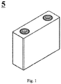
- the prepared soft-packed lithium-ion battery had a thickness of 4.0 mm, a width of 60 mm, and a length of 140 mm.
- LiNi 0.8 Mn 0.1 Co 0.1 O 2 as a positive active material, acetylene black as a conductive agent, and polyvinylidene fluoride (PVDF) as a binder were mixed thoroughly at a weight ratio of 95:3:2 in a solvent system of N-methyl pyrrolidone to obtain the positive electrode slurry.
- the positive electrode slurry was evenly coated on the front and back sides of the aluminum foil with a thickness of 14 ⁇ m; the aluminum foil was dried at room temperature and then transferred to a blower oven at 120°C to dry for 1h, then cold pressed and slit to obtain the positive electrode plate.
- the negative electrode slurry was then uniformly coated on the front and back sides of the current collector copper foil, and the coating amount was 0.0071g/cm 2 , and then it was dried at 85°C and then cold pressed, trimmed, cut, slit, then dried at 110°C for 4 hours under vacuum conditions, then the tabs were welded thereon to prepare the negative electrode plate for lithium ion battery.
- the specific types and proportions of composite materials used in the preparation of negative electrode plate were shown in Table 1. In Table 1, the proportion of the composite material was the weight percentage based on the total weight of the negative active material.
- LiNi 0.8 Mn 0.1 Co 0.1 O 2 as a positive active material, acetylene black as a conductive agent, and polyvinylidene fluoride (PVDF) as a binder were mixed thoroughly at a weight ratio of 95:3:2 in a solvent system of N-methyl pyrrolidone to obtain the positive electrode slurry.
- the positive electrode slurry was evenly coated on the front and back sides of the aluminum foil with a thickness of 14 ⁇ m; the aluminum foil was dried at room temperature and then transferred to a blower oven at 120°C to dry for 1h, then cold pressed and slit to obtain the positive electrode plate.
- a 12 ⁇ m polyethylene film (PE) was used as the separator matrix.
- the above composite material was dissolved in deionized water as a solvent and mixed uniformly to form a slurry, and then the slurry was uniformly coated on the front and back sides of the separator, and then dried at 85°C to form a separator containing the composite material.
- Example 1 No. Position (positive electrode, negative electrode, separator) Composite material Core material Particle size of core material ⁇ m Shell material Weight ratio of core to shell Proportion of composite materials wt% Ratio of weight of composite material in separator to surface area of separator g/m 2 Particle size of composite material ⁇ m Resistivity of composite material ⁇ cm BET of composite material m 2 /g Example 1 Positive electrode Copper 0.1 Silicon dioxide 16 2 ⁇ 1.4 10 7 9 Example 2 Positive electrode Copper 0.3 Silicon dioxide 16 2 ⁇ 1.4 10 7 9 Example 3 Positive electrode Copper 0.5 Silicon dioxide 16 2 ⁇ 1.4 10 7 9 Example 4 Positive electrode Copper 0.3 Silicon dioxide 10 2 ⁇ 1.4 10 7 9 Example 5 Positive electrode Copper 0.3 Silicon dioxide 20 2 ⁇ 1.4 10 7 9 Example 6 Positive electrode Copper 0.3 Silicon dioxide 16 0.5 ⁇ 1.4 10 7 9 Example 7 Positive electrode Copper 0.3 Silicon dioxide 16 5 ⁇ 1.4 10 7 9 Example 8 Positive electrode Copper 0.3 Silicon dioxide 16 2 ⁇
- the lithium-ion battery was charged at a constant current of 1C to 4.2V at 45°C, then charged at a constant voltage of 4.2V to a current of 0.05C, and then discharged at a constant current of 1C to 2.8V. This procedure formed a charge and discharge cycle. Then the battery was subjected to 1000 cycles of charge/discharge test according to the above conditions.
- the capacity retention rate (%) of a lithium-ion battery after 1,000 cycles (discharge capacity for the 1,000th cycle/discharge capacity for the first cycle) ⁇ 100%.
- Comparative Examples 1-2, Comparative Examples 4-7 and Examples 1-21 it can be seen that after adding copper, cuprous oxide or copper sulfide alone to the electrode plate or separator, the battery cannot be charged normally. However, when the core material was coated, i.e., when the composite material according to the present application was used, the basic electrical performance of the battery can be maintained; at the same time, it can be seen from Comparative Example 1 and Examples 1-21 that the addition of composite materials can significantly improve the overcharge performance of the battery .
- Example 2 and Examples 8-9 it can be seen that when the particle size of the composite material was too small, the specific surface area increased, side reactions increased, and the capacity retention rate decreased; and when the particle size of the composite material was too large, the overcharge effect was influenced. From Example 2 and Examples 6-7, it can be seen that when the composite material was present in a relatively low proportion, the overcharge effect was not good.
- Comparative Example 3 and Example 15 it can be seen from Comparative Example 3 and Example 15 that the addition of copper oxide alone can improve overcharge performance, but it affected the battery cycle capacity retention rate. After coating, the battery capacity retention rate was improved, and the improvement of overcharge effect was equivalent to that of uncoated copper oxide, which was related to the mechanism of copper oxide itself.
- Comparative Example 1 Comparative Example 4-5, Example 2 and Example 16-17, it can be seen that copper, cuprous oxide and copper sulfide can better improve the battery overcharge effect after being coated.
- Example 13 and Example 14 It can be seen from Example 13 and Example 14 that for the overcharge performance of lithium-ion batteries, the effect of the silica-coated composite material was better than that of the composite material coated with titanium dioxide.
Landscapes
- Chemical & Material Sciences (AREA)
- Chemical Kinetics & Catalysis (AREA)
- Electrochemistry (AREA)
- General Chemical & Material Sciences (AREA)
- Composite Materials (AREA)
- Engineering & Computer Science (AREA)
- Inorganic Chemistry (AREA)
- Manufacturing & Machinery (AREA)
- Materials Engineering (AREA)
- Ceramic Engineering (AREA)
- Secondary Cells (AREA)
Applications Claiming Priority (2)
| Application Number | Priority Date | Filing Date | Title |
|---|---|---|---|
| CN201911197009.5A CN112885990B (zh) | 2019-11-29 | 2019-11-29 | 一种二次电池 |
| PCT/CN2020/125485 WO2021103934A1 (fr) | 2019-11-29 | 2020-10-30 | Matériau composite ayant une structure cœur-enveloppe pour batterie, batterie secondaire, module de batterie, bloc-batterie et appareil |
Publications (3)
| Publication Number | Publication Date |
|---|---|
| EP3879611A1 true EP3879611A1 (fr) | 2021-09-15 |
| EP3879611A4 EP3879611A4 (fr) | 2022-02-23 |
| EP3879611B1 EP3879611B1 (fr) | 2023-03-29 |
Family
ID=76038341
Family Applications (1)
| Application Number | Title | Priority Date | Filing Date |
|---|---|---|---|
| EP20892294.8A Active EP3879611B1 (fr) | 2019-11-29 | 2020-10-30 | Matériau composite ayant une structure ceur-enveloppe pour batterie, batterie secondaire, module de batterie, bloc-batterie et appareil |
Country Status (4)
| Country | Link |
|---|---|
| US (1) | US11923536B2 (fr) |
| EP (1) | EP3879611B1 (fr) |
| CN (1) | CN112885990B (fr) |
| WO (1) | WO2021103934A1 (fr) |
Family Cites Families (21)
| Publication number | Priority date | Publication date | Assignee | Title |
|---|---|---|---|---|
| WO2002087809A1 (fr) * | 2001-04-27 | 2002-11-07 | Dowa Mining Co., Ltd. | Poudre de cuivre pour pate electroconductrice a excellente resistance a l'oxydation et procede de preparation |
| JP4026587B2 (ja) * | 2003-11-28 | 2007-12-26 | 新神戸電機株式会社 | リチウムイオン電池 |
| JP4670382B2 (ja) * | 2005-02-16 | 2011-04-13 | トヨタ自動車株式会社 | 電池パックおよび自動車 |
| US7498081B2 (en) * | 2005-03-02 | 2009-03-03 | Thw Shwphwed Color Company | Core-shell composite inorganic pigments and method of preparation for crystallizable glass frit compositions |
| US8883354B2 (en) * | 2006-02-15 | 2014-11-11 | Optodot Corporation | Separators for electrochemical cells |
| CN102335605B (zh) * | 2011-09-02 | 2013-04-17 | 中国科学院新疆理化技术研究所 | 一种铜-二氧化钛核壳型纳米粒子的制备方法 |
| EP2753180A1 (fr) * | 2011-09-08 | 2014-07-16 | Corning Incorporated | Matériau composite antimicrobien |
| WO2014095811A1 (fr) * | 2012-12-20 | 2014-06-26 | Umicore | Matière d'électrode négative pour batterie rechargeable et son procédé de production |
| JP5784804B2 (ja) * | 2013-08-22 | 2015-09-24 | シャープ株式会社 | 光触媒材料 |
| WO2015123005A1 (fr) * | 2014-02-14 | 2015-08-20 | Becton, Dickinson And Company | Nanoparticules sers et procédés d'utilisation de ces dernières |
| CN103862039B (zh) * | 2014-03-14 | 2015-12-30 | 中国科学院深圳先进技术研究院 | 核壳结构铜纳米微粒及其制备方法 |
| JP6735660B2 (ja) * | 2016-12-12 | 2020-08-05 | 国立大学法人東北大学 | リチウムイオン二次電池用負極活物質およびその製造方法並びに負極および電池 |
| CN106833024B (zh) * | 2017-01-18 | 2020-04-21 | 江苏泰禾金属工业有限公司 | 核壳结构改性二氧化硅包覆的氧化亚铜及其制备方法 |
| US20180229299A1 (en) * | 2017-02-15 | 2018-08-16 | The Board Of Trustees Of The University Of Arkansas | Copper-silica core-shell nanoparticles and methods |
| CN107302086A (zh) * | 2017-07-19 | 2017-10-27 | 苏州思创源博电子科技有限公司 | 一种氧化钛包覆钠离子三元正极材料的制备方法 |
| CN107732172B (zh) * | 2017-09-25 | 2020-10-30 | 中国计量大学 | 一种锂离子电池负极材料及其制备方法 |
| KR102362799B1 (ko) * | 2017-11-14 | 2022-02-15 | 주식회사 엘지에너지솔루션 | 이차 전지용 양극 및 이를 포함하는 이차 전지 |
| CN108461808A (zh) * | 2018-03-21 | 2018-08-28 | 上海力信能源科技有限责任公司 | 一种高能量密度的锂离子电池及其制备方法 |
| KR102065700B1 (ko) * | 2018-04-26 | 2020-01-13 | 인하대학교 산학협력단 | 애노드 활물질, 그 제조방법 및 이를 포함하는 리튬이온전지 |
| CN109742403A (zh) | 2019-01-16 | 2019-05-10 | 欣旺达电子股份有限公司 | 捕捉氢氟酸的浆料制备方法及锂离子电池 |
| CN110416525B (zh) * | 2019-08-08 | 2022-09-27 | 上海华谊(集团)公司 | 具有核壳结构的含磷酸锰铁锂的复合材料及其制备方法 |
-
2019
- 2019-11-29 CN CN201911197009.5A patent/CN112885990B/zh active Active
-
2020
- 2020-10-30 EP EP20892294.8A patent/EP3879611B1/fr active Active
- 2020-10-30 WO PCT/CN2020/125485 patent/WO2021103934A1/fr not_active Ceased
-
2021
- 2021-06-11 US US17/345,109 patent/US11923536B2/en active Active
Also Published As
| Publication number | Publication date |
|---|---|
| WO2021103934A1 (fr) | 2021-06-03 |
| EP3879611A4 (fr) | 2022-02-23 |
| CN112885990B (zh) | 2022-11-01 |
| US20210305552A1 (en) | 2021-09-30 |
| CN112885990A (zh) | 2021-06-01 |
| EP3879611B1 (fr) | 2023-03-29 |
| US11923536B2 (en) | 2024-03-05 |
Similar Documents
| Publication | Publication Date | Title |
|---|---|---|
| KR102502618B1 (ko) | 이차 전지, 이차 전지를 포함하는 전지 모듈, 전지 팩 및 장치 | |
| EP3905412B1 (fr) | Batterie lithium-ion et module de batterie, bloc-batterie et dispositif associés | |
| CN103563155B (zh) | 包含碳氟化合物电解质添加剂的锂离子电化学电池 | |
| EP4160773B1 (fr) | Électrolyte, batterie secondaire, module de batterie, bloc-batterie et dispositif électrique | |
| WO2020063371A1 (fr) | Élément d'électrode positive et batterie secondaire au lithium-ion | |
| EP3614462A1 (fr) | Plaque d'électrode négative et batterie secondaire | |
| EP4047711A1 (fr) | Module de batterie, bloc-batterie, appareil électronique, et procédé de fabrication de module de batterie et dispositif de fabrication | |
| CN110265625A (zh) | 负极极片及锂离子二次电池 | |
| JP2008300180A (ja) | 非水電解質二次電池 | |
| CN116848692A (zh) | 二次电池、电池模块、电池包和用电装置 | |
| EP4333117A1 (fr) | Matériau actif d'électrode positive et son procédé de préparation, batterie au lithium-ion le comprenant, module de batterie, bloc-batterie et appareil électrique | |
| JP7106762B2 (ja) | 正極シート及びその製造方法、並びにリチウムイオン二次電池 | |
| CN111162247B (zh) | 正极极片及锂离子二次电池 | |
| WO2022133961A1 (fr) | Batterie rechargeable au lithium, module de batterie la comprenant, bloc-batterie et appareil électrique | |
| CN111430801B (zh) | 锂离子二次电池的电解液及其应用 | |
| CN113130992B (zh) | 一种非水电解液及锂离子电池 | |
| EP4451452A1 (fr) | Séparateur, batterie secondaire l'utilisant, module de batterie, bloc-batterie et appareil électrique | |
| CN115842090A (zh) | 负极极片及其制备方法、二次电池、电池模块、电池包、用电装置 | |
| US20160204430A1 (en) | Nonaqueous electrolyte secondary battery | |
| CN113555604A (zh) | 锂离子电池 | |
| US8563179B2 (en) | Nonaqueous secondary battery | |
| CN120015825A (zh) | 一种电池单体、电池装置和用电装置 | |
| EP4213264A1 (fr) | Électrolyte, batterie secondaire, module de batterie, bloc-batterie et dispositif électrique | |
| EP4421916A1 (fr) | Batterie secondaire au lithium-ion, module de batterie, bloc-batterie et appareil électrique | |
| WO2023087241A1 (fr) | Groupe de batteries, bloc-batterie, appareil électrique, procédé de fabrication et dispositif de fabrication de groupe de batteries, et procédé de commande de groupe de batteries |
Legal Events
| Date | Code | Title | Description |
|---|---|---|---|
| STAA | Information on the status of an ep patent application or granted ep patent |
Free format text: STATUS: THE INTERNATIONAL PUBLICATION HAS BEEN MADE |
|
| PUAI | Public reference made under article 153(3) epc to a published international application that has entered the european phase |
Free format text: ORIGINAL CODE: 0009012 |
|
| STAA | Information on the status of an ep patent application or granted ep patent |
Free format text: STATUS: REQUEST FOR EXAMINATION WAS MADE |
|
| 17P | Request for examination filed |
Effective date: 20210610 |
|
| AK | Designated contracting states |
Kind code of ref document: A1 Designated state(s): AL AT BE BG CH CY CZ DE DK EE ES FI FR GB GR HR HU IE IS IT LI LT LU LV MC MK MT NL NO PL PT RO RS SE SI SK SM TR |
|
| A4 | Supplementary search report drawn up and despatched |
Effective date: 20220126 |
|
| RIC1 | Information provided on ipc code assigned before grant |
Ipc: H01M 4/02 20060101ALN20220120BHEP Ipc: H01M 4/525 20100101ALN20220120BHEP Ipc: H01M 4/587 20100101ALN20220120BHEP Ipc: H01M 10/42 20060101ALI20220120BHEP Ipc: H01M 50/434 20210101ALI20220120BHEP Ipc: H01M 50/431 20210101ALI20220120BHEP Ipc: H01M 10/0525 20100101ALI20220120BHEP Ipc: H01M 4/48 20100101ALI20220120BHEP Ipc: H01M 4/36 20060101ALI20220120BHEP Ipc: H01M 4/62 20060101AFI20220120BHEP |
|
| RIC1 | Information provided on ipc code assigned before grant |
Ipc: H01M 4/02 20060101ALN20221110BHEP Ipc: H01M 4/525 20100101ALN20221110BHEP Ipc: H01M 4/587 20100101ALN20221110BHEP Ipc: H01M 10/42 20060101ALI20221110BHEP Ipc: H01M 50/434 20210101ALI20221110BHEP Ipc: H01M 50/431 20210101ALI20221110BHEP Ipc: H01M 10/0525 20100101ALI20221110BHEP Ipc: H01M 4/48 20100101ALI20221110BHEP Ipc: H01M 4/36 20060101ALI20221110BHEP Ipc: H01M 4/62 20060101AFI20221110BHEP |
|
| GRAP | Despatch of communication of intention to grant a patent |
Free format text: ORIGINAL CODE: EPIDOSNIGR1 |
|
| STAA | Information on the status of an ep patent application or granted ep patent |
Free format text: STATUS: GRANT OF PATENT IS INTENDED |
|
| DAV | Request for validation of the european patent (deleted) | ||
| DAX | Request for extension of the european patent (deleted) | ||
| INTG | Intention to grant announced |
Effective date: 20221221 |
|
| GRAS | Grant fee paid |
Free format text: ORIGINAL CODE: EPIDOSNIGR3 |
|
| GRAA | (expected) grant |
Free format text: ORIGINAL CODE: 0009210 |
|
| STAA | Information on the status of an ep patent application or granted ep patent |
Free format text: STATUS: THE PATENT HAS BEEN GRANTED |
|
| AK | Designated contracting states |
Kind code of ref document: B1 Designated state(s): AL AT BE BG CH CY CZ DE DK EE ES FI FR GB GR HR HU IE IS IT LI LT LU LV MC MK MT NL NO PL PT RO RS SE SI SK SM TR |
|
| REG | Reference to a national code |
Ref country code: CH Ref legal event code: EP |
|
| REG | Reference to a national code |
Ref country code: DE Ref legal event code: R096 Ref document number: 602020009324 Country of ref document: DE |
|
| REG | Reference to a national code |
Ref country code: AT Ref legal event code: REF Ref document number: 1557284 Country of ref document: AT Kind code of ref document: T Effective date: 20230415 |
|
| REG | Reference to a national code |
Ref country code: IE Ref legal event code: FG4D |
|
| REG | Reference to a national code |
Ref country code: SE Ref legal event code: TRGR |
|
| P01 | Opt-out of the competence of the unified patent court (upc) registered |
Effective date: 20230516 |
|
| REG | Reference to a national code |
Ref country code: LT Ref legal event code: MG9D |
|
| PG25 | Lapsed in a contracting state [announced via postgrant information from national office to epo] |
Ref country code: RS Free format text: LAPSE BECAUSE OF FAILURE TO SUBMIT A TRANSLATION OF THE DESCRIPTION OR TO PAY THE FEE WITHIN THE PRESCRIBED TIME-LIMIT Effective date: 20230329 Ref country code: NO Free format text: LAPSE BECAUSE OF FAILURE TO SUBMIT A TRANSLATION OF THE DESCRIPTION OR TO PAY THE FEE WITHIN THE PRESCRIBED TIME-LIMIT Effective date: 20230629 Ref country code: LV Free format text: LAPSE BECAUSE OF FAILURE TO SUBMIT A TRANSLATION OF THE DESCRIPTION OR TO PAY THE FEE WITHIN THE PRESCRIBED TIME-LIMIT Effective date: 20230329 Ref country code: LT Free format text: LAPSE BECAUSE OF FAILURE TO SUBMIT A TRANSLATION OF THE DESCRIPTION OR TO PAY THE FEE WITHIN THE PRESCRIBED TIME-LIMIT Effective date: 20230329 Ref country code: HR Free format text: LAPSE BECAUSE OF FAILURE TO SUBMIT A TRANSLATION OF THE DESCRIPTION OR TO PAY THE FEE WITHIN THE PRESCRIBED TIME-LIMIT Effective date: 20230329 |
|
| REG | Reference to a national code |
Ref country code: NL Ref legal event code: MP Effective date: 20230329 |
|
| REG | Reference to a national code |
Ref country code: AT Ref legal event code: MK05 Ref document number: 1557284 Country of ref document: AT Kind code of ref document: T Effective date: 20230329 |
|
| PG25 | Lapsed in a contracting state [announced via postgrant information from national office to epo] |
Ref country code: NL Free format text: LAPSE BECAUSE OF FAILURE TO SUBMIT A TRANSLATION OF THE DESCRIPTION OR TO PAY THE FEE WITHIN THE PRESCRIBED TIME-LIMIT Effective date: 20230329 Ref country code: GR Free format text: LAPSE BECAUSE OF FAILURE TO SUBMIT A TRANSLATION OF THE DESCRIPTION OR TO PAY THE FEE WITHIN THE PRESCRIBED TIME-LIMIT Effective date: 20230630 Ref country code: FI Free format text: LAPSE BECAUSE OF FAILURE TO SUBMIT A TRANSLATION OF THE DESCRIPTION OR TO PAY THE FEE WITHIN THE PRESCRIBED TIME-LIMIT Effective date: 20230329 |
|
| PG25 | Lapsed in a contracting state [announced via postgrant information from national office to epo] |
Ref country code: SM Free format text: LAPSE BECAUSE OF FAILURE TO SUBMIT A TRANSLATION OF THE DESCRIPTION OR TO PAY THE FEE WITHIN THE PRESCRIBED TIME-LIMIT Effective date: 20230329 Ref country code: RO Free format text: LAPSE BECAUSE OF FAILURE TO SUBMIT A TRANSLATION OF THE DESCRIPTION OR TO PAY THE FEE WITHIN THE PRESCRIBED TIME-LIMIT Effective date: 20230329 Ref country code: PT Free format text: LAPSE BECAUSE OF FAILURE TO SUBMIT A TRANSLATION OF THE DESCRIPTION OR TO PAY THE FEE WITHIN THE PRESCRIBED TIME-LIMIT Effective date: 20230731 Ref country code: ES Free format text: LAPSE BECAUSE OF FAILURE TO SUBMIT A TRANSLATION OF THE DESCRIPTION OR TO PAY THE FEE WITHIN THE PRESCRIBED TIME-LIMIT Effective date: 20230329 Ref country code: EE Free format text: LAPSE BECAUSE OF FAILURE TO SUBMIT A TRANSLATION OF THE DESCRIPTION OR TO PAY THE FEE WITHIN THE PRESCRIBED TIME-LIMIT Effective date: 20230329 Ref country code: AT Free format text: LAPSE BECAUSE OF FAILURE TO SUBMIT A TRANSLATION OF THE DESCRIPTION OR TO PAY THE FEE WITHIN THE PRESCRIBED TIME-LIMIT Effective date: 20230329 |
|
| PG25 | Lapsed in a contracting state [announced via postgrant information from national office to epo] |
Ref country code: SK Free format text: LAPSE BECAUSE OF FAILURE TO SUBMIT A TRANSLATION OF THE DESCRIPTION OR TO PAY THE FEE WITHIN THE PRESCRIBED TIME-LIMIT Effective date: 20230329 Ref country code: PL Free format text: LAPSE BECAUSE OF FAILURE TO SUBMIT A TRANSLATION OF THE DESCRIPTION OR TO PAY THE FEE WITHIN THE PRESCRIBED TIME-LIMIT Effective date: 20230329 Ref country code: IS Free format text: LAPSE BECAUSE OF FAILURE TO SUBMIT A TRANSLATION OF THE DESCRIPTION OR TO PAY THE FEE WITHIN THE PRESCRIBED TIME-LIMIT Effective date: 20230729 |
|
| REG | Reference to a national code |
Ref country code: DE Ref legal event code: R097 Ref document number: 602020009324 Country of ref document: DE |
|
| PG25 | Lapsed in a contracting state [announced via postgrant information from national office to epo] |
Ref country code: DK Free format text: LAPSE BECAUSE OF FAILURE TO SUBMIT A TRANSLATION OF THE DESCRIPTION OR TO PAY THE FEE WITHIN THE PRESCRIBED TIME-LIMIT Effective date: 20230329 Ref country code: CZ Free format text: LAPSE BECAUSE OF FAILURE TO SUBMIT A TRANSLATION OF THE DESCRIPTION OR TO PAY THE FEE WITHIN THE PRESCRIBED TIME-LIMIT Effective date: 20230329 |
|
| PLBE | No opposition filed within time limit |
Free format text: ORIGINAL CODE: 0009261 |
|
| STAA | Information on the status of an ep patent application or granted ep patent |
Free format text: STATUS: NO OPPOSITION FILED WITHIN TIME LIMIT |
|
| 26N | No opposition filed |
Effective date: 20240103 |
|
| PG25 | Lapsed in a contracting state [announced via postgrant information from national office to epo] |
Ref country code: SI Free format text: LAPSE BECAUSE OF FAILURE TO SUBMIT A TRANSLATION OF THE DESCRIPTION OR TO PAY THE FEE WITHIN THE PRESCRIBED TIME-LIMIT Effective date: 20230329 |
|
| PG25 | Lapsed in a contracting state [announced via postgrant information from national office to epo] |
Ref country code: SI Free format text: LAPSE BECAUSE OF FAILURE TO SUBMIT A TRANSLATION OF THE DESCRIPTION OR TO PAY THE FEE WITHIN THE PRESCRIBED TIME-LIMIT Effective date: 20230329 Ref country code: IT Free format text: LAPSE BECAUSE OF FAILURE TO SUBMIT A TRANSLATION OF THE DESCRIPTION OR TO PAY THE FEE WITHIN THE PRESCRIBED TIME-LIMIT Effective date: 20230329 Ref country code: MC Free format text: LAPSE BECAUSE OF FAILURE TO SUBMIT A TRANSLATION OF THE DESCRIPTION OR TO PAY THE FEE WITHIN THE PRESCRIBED TIME-LIMIT Effective date: 20230329 |
|
| REG | Reference to a national code |
Ref country code: CH Ref legal event code: PL |
|
| REG | Reference to a national code |
Ref country code: BE Ref legal event code: MM Effective date: 20231031 |
|
| PG25 | Lapsed in a contracting state [announced via postgrant information from national office to epo] |
Ref country code: LU Free format text: LAPSE BECAUSE OF NON-PAYMENT OF DUE FEES Effective date: 20231030 |
|
| PG25 | Lapsed in a contracting state [announced via postgrant information from national office to epo] |
Ref country code: LU Free format text: LAPSE BECAUSE OF NON-PAYMENT OF DUE FEES Effective date: 20231030 |
|
| PG25 | Lapsed in a contracting state [announced via postgrant information from national office to epo] |
Ref country code: CH Free format text: LAPSE BECAUSE OF NON-PAYMENT OF DUE FEES Effective date: 20231031 |
|
| PG25 | Lapsed in a contracting state [announced via postgrant information from national office to epo] |
Ref country code: CH Free format text: LAPSE BECAUSE OF NON-PAYMENT OF DUE FEES Effective date: 20231031 |
|
| REG | Reference to a national code |
Ref country code: DE Ref legal event code: R081 Ref document number: 602020009324 Country of ref document: DE Owner name: CONTEMPORARY AMPEREX TECHNOLOGY (HONG KONG) LI, HK Free format text: FORMER OWNER: CONTEMPORARY AMPEREX TECHNOLOGY CO., LIMITED, NINGDE CITY, FUJIAN, CN |
|
| PG25 | Lapsed in a contracting state [announced via postgrant information from national office to epo] |
Ref country code: BE Free format text: LAPSE BECAUSE OF NON-PAYMENT OF DUE FEES Effective date: 20231031 |
|
| REG | Reference to a national code |
Ref country code: GB Ref legal event code: 732E Free format text: REGISTERED BETWEEN 20240829 AND 20240904 |
|
| PG25 | Lapsed in a contracting state [announced via postgrant information from national office to epo] |
Ref country code: IE Free format text: LAPSE BECAUSE OF NON-PAYMENT OF DUE FEES Effective date: 20231030 |
|
| PG25 | Lapsed in a contracting state [announced via postgrant information from national office to epo] |
Ref country code: IE Free format text: LAPSE BECAUSE OF NON-PAYMENT OF DUE FEES Effective date: 20231030 |
|
| PG25 | Lapsed in a contracting state [announced via postgrant information from national office to epo] |
Ref country code: BG Free format text: LAPSE BECAUSE OF FAILURE TO SUBMIT A TRANSLATION OF THE DESCRIPTION OR TO PAY THE FEE WITHIN THE PRESCRIBED TIME-LIMIT Effective date: 20230329 |
|
| PG25 | Lapsed in a contracting state [announced via postgrant information from national office to epo] |
Ref country code: BG Free format text: LAPSE BECAUSE OF FAILURE TO SUBMIT A TRANSLATION OF THE DESCRIPTION OR TO PAY THE FEE WITHIN THE PRESCRIBED TIME-LIMIT Effective date: 20230329 |
|
| PG25 | Lapsed in a contracting state [announced via postgrant information from national office to epo] |
Ref country code: CY Free format text: LAPSE BECAUSE OF FAILURE TO SUBMIT A TRANSLATION OF THE DESCRIPTION OR TO PAY THE FEE WITHIN THE PRESCRIBED TIME-LIMIT; INVALID AB INITIO Effective date: 20201030 |
|
| PG25 | Lapsed in a contracting state [announced via postgrant information from national office to epo] |
Ref country code: HU Free format text: LAPSE BECAUSE OF FAILURE TO SUBMIT A TRANSLATION OF THE DESCRIPTION OR TO PAY THE FEE WITHIN THE PRESCRIBED TIME-LIMIT; INVALID AB INITIO Effective date: 20201030 |
|
| PGFP | Annual fee paid to national office [announced via postgrant information from national office to epo] |
Ref country code: GB Payment date: 20250911 Year of fee payment: 6 |
|
| PGFP | Annual fee paid to national office [announced via postgrant information from national office to epo] |
Ref country code: FR Payment date: 20250908 Year of fee payment: 6 |
|
| PGFP | Annual fee paid to national office [announced via postgrant information from national office to epo] |
Ref country code: SE Payment date: 20250910 Year of fee payment: 6 |
|
| PG25 | Lapsed in a contracting state [announced via postgrant information from national office to epo] |
Ref country code: TR Free format text: LAPSE BECAUSE OF FAILURE TO SUBMIT A TRANSLATION OF THE DESCRIPTION OR TO PAY THE FEE WITHIN THE PRESCRIBED TIME-LIMIT Effective date: 20230329 |
|
| PGFP | Annual fee paid to national office [announced via postgrant information from national office to epo] |
Ref country code: DE Payment date: 20250902 Year of fee payment: 6 |