EP3880095B1 - Procédé de fixation de l'arbre d'un instrument chirurgical au boîtier d'instrument - Google Patents
Procédé de fixation de l'arbre d'un instrument chirurgical au boîtier d'instrument Download PDFInfo
- Publication number
- EP3880095B1 EP3880095B1 EP19818327.9A EP19818327A EP3880095B1 EP 3880095 B1 EP3880095 B1 EP 3880095B1 EP 19818327 A EP19818327 A EP 19818327A EP 3880095 B1 EP3880095 B1 EP 3880095B1
- Authority
- EP
- European Patent Office
- Prior art keywords
- pair
- outer shaft
- tracks
- tube stop
- housing
- Prior art date
- Legal status (The legal status is an assumption and is not a legal conclusion. Google has not performed a legal analysis and makes no representation as to the accuracy of the status listed.)
- Active
Links
Images


Classifications
-
- A—HUMAN NECESSITIES
- A61—MEDICAL OR VETERINARY SCIENCE; HYGIENE
- A61B—DIAGNOSIS; SURGERY; IDENTIFICATION
- A61B17/00—Surgical instruments, devices or methods
- A61B17/28—Surgical forceps
- A61B17/29—Forceps for use in minimally invasive surgery
-
- A—HUMAN NECESSITIES
- A61—MEDICAL OR VETERINARY SCIENCE; HYGIENE
- A61B—DIAGNOSIS; SURGERY; IDENTIFICATION
- A61B17/00—Surgical instruments, devices or methods
- A61B17/12—Surgical instruments, devices or methods for ligaturing or otherwise compressing tubular parts of the body, e.g. blood vessels or umbilical cord
- A61B17/12009—Implements for ligaturing other than by clamps or clips, e.g. using a loop with a slip knot
-
- A—HUMAN NECESSITIES
- A61—MEDICAL OR VETERINARY SCIENCE; HYGIENE
- A61B—DIAGNOSIS; SURGERY; IDENTIFICATION
- A61B17/00—Surgical instruments, devices or methods
- A61B2017/00367—Details of actuation of instruments, e.g. relations between pushing buttons, or the like, and activation of the tool, working tip, or the like
-
- A—HUMAN NECESSITIES
- A61—MEDICAL OR VETERINARY SCIENCE; HYGIENE
- A61B—DIAGNOSIS; SURGERY; IDENTIFICATION
- A61B17/00—Surgical instruments, devices or methods
- A61B2017/00477—Coupling
-
- A—HUMAN NECESSITIES
- A61—MEDICAL OR VETERINARY SCIENCE; HYGIENE
- A61B—DIAGNOSIS; SURGERY; IDENTIFICATION
- A61B17/00—Surgical instruments, devices or methods
- A61B2017/00526—Methods of manufacturing
-
- A—HUMAN NECESSITIES
- A61—MEDICAL OR VETERINARY SCIENCE; HYGIENE
- A61B—DIAGNOSIS; SURGERY; IDENTIFICATION
- A61B17/00—Surgical instruments, devices or methods
- A61B17/28—Surgical forceps
- A61B17/29—Forceps for use in minimally invasive surgery
- A61B2017/2901—Details of shaft
- A61B2017/2902—Details of shaft characterized by features of the actuating rod
-
- A—HUMAN NECESSITIES
- A61—MEDICAL OR VETERINARY SCIENCE; HYGIENE
- A61B—DIAGNOSIS; SURGERY; IDENTIFICATION
- A61B17/00—Surgical instruments, devices or methods
- A61B17/28—Surgical forceps
- A61B17/29—Forceps for use in minimally invasive surgery
- A61B2017/2926—Details of heads or jaws
- A61B2017/2927—Details of heads or jaws the angular position of the head being adjustable with respect to the shaft
- A61B2017/2929—Details of heads or jaws the angular position of the head being adjustable with respect to the shaft with a head rotatable about the longitudinal axis of the shaft
-
- A—HUMAN NECESSITIES
- A61—MEDICAL OR VETERINARY SCIENCE; HYGIENE
- A61B—DIAGNOSIS; SURGERY; IDENTIFICATION
- A61B17/00—Surgical instruments, devices or methods
- A61B17/28—Surgical forceps
- A61B17/29—Forceps for use in minimally invasive surgery
- A61B2017/2926—Details of heads or jaws
- A61B2017/2932—Transmission of forces to jaw members
- A61B2017/2939—Details of linkages or pivot points
- A61B2017/294—Connection of actuating rod to jaw, e.g. releasable
Definitions
- the present invention relates to surgical instruments and, more specifically, to an approach for securing an elongated shaft to a housing for rotational movement.
- Surgical instruments such as vessel sealers and like, include a handle from which a shaft extends and supports a surgical implement, such as a pair of jaws, that may be operated by a surgeon to perform a procedure. Positioning of the implement with a patient may require rotation of the entire surgical instrument to rotate the implement at the end of the shaft. For example, in order to position the jaws of a vessel sealer about a vessel, the jaws may need to be rotated by the surgeon so that the jaws can encompass the vessel prior to closing the jaws. As a result, there is a need in the art for an approach that can allow a user to more easily rotate the implement at the end of the shaft during a procedure so that the instrument can be more properly aligned for the procedure.
- DE 101 56 917 A1 discloses a surgical instrument with the features in the preamble of present claim 1. Further conventional surgical instruments are described in EP 3 241 510 A1 and WO 2017/100412 A1 .
- the present invention secures the shaft of a surgical instrument to the housing of the instrument while allowing for rotation of the shaft via a rotator knob. More specifically, disclosed is a surgical instrument having a housing, an outer shaft extending from the housing along a longitudinal axis, an inner shaft extending within the outer shaft along the longitudinal axis, a rotator knob position about the outer shaft, and a tube stop coupling the rotator knob to the outer shaft for collective rotation about the longitudinal axis and fixed within the housing against movement along the longitudinal axis.
- a pair of tracks extend longitudinally in the outer shaft.
- the tube stop has a pair of bearing surfaces that extend into the pair of tracks, respectively.
- the rotator knob includes a pair of rails that extend into the pair of tracks of the outer shaft, respectively.
- Each of the pair of tracks include a first portion extending longitudinally in the outer shaft and a second portion extending circumferentially from an end of the first portion.
- Each of the pair of bearing surfaces of the tube stop are positioned in the second portion of each of the pair of tracks, respectively.
- the rails of the rotator knob extend to the end of the portion of each of the tracks to block the tube stop from rotation out of the second portion of each of the tracks.
- the tube stop is captured between a pair of ribs in the housing.
- the tube stop includes a second pair of bearing surfaces that engage the outer shaft.
- the tube stop includes a third pair of bearing surfaces that engage the ribs of the rotator knob.
- the present invention also includes a method of coupling elements of a surgical instrument for common rotation.
- the method includes the steps of providing a housing, an outer shaft extending from the housing along a longitudinal axis, an inner shaft extending within the outer shaft along the longitudinal axis, positioning a tube stop about the outer shaft, positioning a rotator knob about the outer shaft in abutment with the tube stop and in interlocking engagement with the outer shaft, and fixing the tube stop within the housing to prevent movement of the tube stop along the longitudinal axis.
- the rotator knob includes a pair of rails that extend within a pair of tracks of the outer shaft, respectively. A pair of bearing surfaces of the tube stop extend into the pair of tracks, respectively, and are fixed in place by the pair of rails of the rotator knob.
- Each of the pair of tracks includes a first portion that accepts one of the pair of rails of the rotator knobs and a second portion that extends circumferentially from the first portion and accepts one of the bearing surfaces of the tube stop.
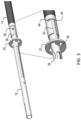
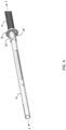
- FIG. 1 a surgical instrument 10 having a housing 12.
- housing 12 is shaped to allow a surgeon to grasp a proximal end of surgical instrument 10 for use during a surgical procedure.
- Surgical instrument 10 further comprises an outer shaft 14 that extends distally from a portion of housing 12 along a longitudinal axis X-X.
- An inner shaft 16 that extends within outer shaft 14.
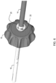
- a rotator knob 18 is interconnected to outer shaft 14 to allow a user to rotate outer shaft 14.
- a tube stop 20 engages both outer shaft 14 and rotator knob 18 to interlock outer shaft 14 and rotator knob 18 for common rotation.
- tube stop 20 comprises a body 22 formed as a disk and including an opening 24 therethrough. Opening 24 is defined by a first set of bearing surfaces 26, a second set of bearing surfaces 28, and a third set of bearing surfaces 30.
- First set of bearing surfaces 26 engage the outer surface 32 of outer shaft 14.
- Second set of bearing surfaces 28 engage the outer surface 34 of inner shaft 16 via a corresponding pair of tracks 36 formed through outer shaft 14.
- Third set of surfaces 30 engage a pair of corresponding rails 40 extending longitudinally from rotator knob 18, as seen in FIGS. 7A and 7B .
- tube stop 20 is positioned about outer shaft 14 and inner shaft 16 is positioned within outer shaft 14.
- Second set of bearing surfaces 28 are aligned with tracks 36 formed into the outer surface 38 of outer shaft 14.
- tracks 36 include a first portion 42 that extends longitudinally in parallel with axis X-X from the end of outer shaft 14 from the end of outer shaft 14 to an internal end 46.
- a second portion 44 extends circumferentially about a portion of outer shaft 14 from end 46 of first portion 42 at right angles to first portion 42 and thus axis X-X.
- second portion 44 is in communication with first portion 42 so that second set of bearing surfaces 28 of tube stop 20 may be passed along first portion 42 and then rotated into second portion 44, thereby capturing second set of bearing surfaces 28 within second portion 44 of tracks 36 and preventing longitudinal movement of bearing surfaces 28.
- rotator knob 18 is passed over inner shaft 16 so that rails 40 engage third set of bearing surfaces 30.
- Rails 40 are shaped to slide along tracks 36 of outer shaft 14 to end 46 of first portion 42, thereby blocking tube stop 20 from rotating out of second portion 44 of tracks 36.
- the interconnection between rails 40 of rotator knob 18 and tracks 36 interlocks rotator knob 18 with outer shaft 14 for co-rotation therewith.
- Third set of bearing surfaces 30 capture rails 40 securely to hold rails within tracks 36.
- housing 12 includes a pair of spaced apart ribs 50 positioned to capture and hold tube stop 20 within housing 12. Ribs 50 thus prevent proximal or distal movement of tube stop 20 along axis X-X, thereby securing outer shaft 14 relative to housing 12, as seen in FIG. 9 .
- Inner shaft 16 extends proximally through housing 12 and is capable of longitudinal movement along axis X-X while shaft 14 is fixed against movement. Rotation of rotator knob 18 will cause rotation of outer shaft 14 but not inner shaft 16.
- inner shaft 16 may be coupled to a mechanism in housing 12 that can cause movement of inner shaft 16 relative to outer shaft 14 to drive a surgical implement positioned at the distal end of inner shaft 16, such as a pair of opposing jaws or the like.
Landscapes
- Health & Medical Sciences (AREA)
- Surgery (AREA)
- Life Sciences & Earth Sciences (AREA)
- Heart & Thoracic Surgery (AREA)
- Molecular Biology (AREA)
- Veterinary Medicine (AREA)
- Engineering & Computer Science (AREA)
- Biomedical Technology (AREA)
- Public Health (AREA)
- Medical Informatics (AREA)
- Nuclear Medicine, Radiotherapy & Molecular Imaging (AREA)
- Animal Behavior & Ethology (AREA)
- General Health & Medical Sciences (AREA)
- Ophthalmology & Optometry (AREA)
- Reproductive Health (AREA)
- Vascular Medicine (AREA)
- Surgical Instruments (AREA)
Claims (9)
- Instrument chirurgical (10), comprenant :un boîtier (12) ;un arbre extérieur (14) s'étendant depuis le boîtier (12) le long d'un axe longitudinal (X) ;un arbre intérieur (16) s'étendant à l'intérieur de l'arbre extérieur (14) le long de l'axe longitudinal (X) ;un bouton rotatif (18) positionné autour de l'arbre extérieur (14) ;une butée de tube (20) couplant le bouton rotatif (18) à l'arbre extérieur (14) pour une rotation collective autour de l'axe longitudinal (X) et fixée à l'intérieur du boîtier (12) contre un mouvement le long de l'axe longitudinal (X) ; etune paire de pistes (36),caractérisé en ce quela paire de pistes (36) s'étend longitudinalement dans l'arbre extérieur (14),la butée de tube (20) comprend une paire de surfaces d'appui (28) s'étendant à l'intérieur de la paire de pistes (36), respectivement, etle bouton rotatif (18) inclut une paire de rails (40), qui s'étendent à l'intérieur de la paire de pistes (36) de l'arbre extérieur (14), respectivement.
- Instrument chirurgical (10) selon la revendication 1, dans lequel chacune de la paire de pistes (36) inclut une première partie (42) s'étend longitudinalement dans l'arbre extérieur (14) et une deuxième partie (44) s'étendant circonférentiellement depuis une extrémité de la première partie (42).
- Instrument chirurgical (10) selon la revendication 2, dans lequel chacune de la paire de surfaces d'appui (28) de la butée de tube (20) est positionnée dans la deuxième partie (44) de chacune de la paire de pistes (36), respectivement.
- Instrument chirurgical (10) selon la revendication 3, dans lequel la paire de rails (40) du bouton rotatif (18) s'étendent jusqu'à l'extrémité de la partie de chacune des pistes (36) pour empêcher la butée de tube (20) de tourner hors de la deuxième partie (44) de chacune des pistes (36).
- Instrument chirurgical (10) selon la revendication 4, dans lequel la butée de tube (20) est capturée entre une paire de nervures (50) dans le boîtier (12).
- Instrument chirurgical (10) selon la revendication 5, dans lequel la butée de tube (20) inclut une deuxième paire de surfaces d'appui (26) qui engagent l'arbre extérieur (14).
- Instrument chirurgical (10) selon la revendication 6, dans lequel la butée de tube (20) inclut une troisième paire de surfaces d'appui (30) qui engagent la paire de nervures (50) du bouton rotatif (18), respectivement.
- Procédé de couplage d'éléments d'un instrument chirurgical (10) pour une rotation commune, comprenant les étapes de :prévision d'un boîtier (12), d'un arbre extérieur (14) s'étendant depuis le boîtier (12) le long d'un axe longitudinal (X), d'un arbre intérieur (16) s'étendant à l'intérieur de l'arbre extérieur (14) le long de l'axe longitudinal (X) ;positionnement d'une butée de tube (20) autour de l'arbre extérieur (14) ;positionnement d'un bouton rotatif (18) autour de l'arbre extérieur (14) en butée avec la butée de tube (20) et en engagement d'inter-verrouillage avec l'arbre extérieur (14) ; etfixation de la butée de tube (20) à l'intérieur du boîtier (12) pour empêcher un mouvement de la butée de tube (20) le long de l'axe longitudinal (X),dans lequel une paire de pistes (36) s'étend longitudinalement dans l'arbre extérieur (14), et le bouton rotatif (18) inclut une paire de rails (40) qui s'étendent à l'intérieur de la paire de pistes (36) de l'arbre extérieur (14), respectivement, etdans lequel une paire de surfaces d'appui (28) de la butée de tube (20) s'étendent à l'intérieur de la paire de pistes (36), respectivement, et sont fixées en place par la paire de rails (40) du bouton rotatif (18).
- Procédé selon la revendication 8, dans lequel chacune de la paire de pistes (36) inclut une première partie (42) qui accepte un de la paire de rails (40) des boutons rotatifs (18) et une deuxième partie (44) qui s'étend circonférentiellement depuis la première partie (42) et accepte une des surfaces d'appui (28) de la butée de tube (20).
Applications Claiming Priority (2)
| Application Number | Priority Date | Filing Date | Title |
|---|---|---|---|
| US201862767014P | 2018-11-14 | 2018-11-14 | |
| PCT/US2019/061075 WO2020102275A1 (fr) | 2018-11-14 | 2019-11-13 | Procédé de fixation de l'arbre d'un instrument chirurgical au boîtier d'instrument |
Publications (2)
| Publication Number | Publication Date |
|---|---|
| EP3880095A1 EP3880095A1 (fr) | 2021-09-22 |
| EP3880095B1 true EP3880095B1 (fr) | 2023-06-28 |
Family
ID=68848384
Family Applications (1)
| Application Number | Title | Priority Date | Filing Date |
|---|---|---|---|
| EP19818327.9A Active EP3880095B1 (fr) | 2018-11-14 | 2019-11-13 | Procédé de fixation de l'arbre d'un instrument chirurgical au boîtier d'instrument |
Country Status (9)
| Country | Link |
|---|---|
| US (1) | US12295603B2 (fr) |
| EP (1) | EP3880095B1 (fr) |
| JP (1) | JP7220781B2 (fr) |
| KR (1) | KR102580180B1 (fr) |
| CN (1) | CN113038890B (fr) |
| AU (1) | AU2019380422B2 (fr) |
| CA (1) | CA3117472C (fr) |
| ES (1) | ES2957402T3 (fr) |
| WO (1) | WO2020102275A1 (fr) |
Families Citing this family (1)
| Publication number | Priority date | Publication date | Assignee | Title |
|---|---|---|---|---|
| CN119326464B (zh) * | 2024-08-08 | 2025-08-15 | 江苏孜航精密五金有限公司 | 摆头角度手动复位机构及其电动腔镜吻合器 |
Family Cites Families (13)
| Publication number | Priority date | Publication date | Assignee | Title |
|---|---|---|---|---|
| CA2050868C (fr) | 1990-10-05 | 2002-01-01 | Ernie Aranyi | Instrument chirurgical d'endoscopie |
| US5352235A (en) * | 1992-03-16 | 1994-10-04 | Tibor Koros | Laparoscopic grasper and cutter |
| DE10156917B4 (de) * | 2001-11-21 | 2006-04-20 | Günter Bissinger Medizintechnik GmbH | Instrument für die endoskopische Chirurgie |
| AU2003219465A1 (en) * | 2002-04-30 | 2003-11-17 | Precimed S.A. | Reamer spindle for minimally invasive joint surgery |
| EP2635221A1 (fr) * | 2010-11-05 | 2013-09-11 | Ethicon Endo-Surgery, Inc. | Instrument chirurgical avec bloc de pince modulaire |
| US8852185B2 (en) * | 2011-05-19 | 2014-10-07 | Covidien Lp | Apparatus for performing an electrosurgical procedure |
| DE102012207651A1 (de) * | 2012-05-08 | 2013-11-14 | Aesculap Ag | Schnellspann-Kupplung |
| US9549750B2 (en) * | 2014-03-31 | 2017-01-24 | Ethicon Endo-Surgery, Llc | Surgical devices with articulating end effectors and methods of using surgical devices with articulating end effectors |
| US10463422B2 (en) * | 2014-12-18 | 2019-11-05 | Covidien Lp | Surgical instrument with stopper assembly |
| US10111698B2 (en) * | 2015-04-16 | 2018-10-30 | Ethicon Llc | Surgical instrument with rotatable shaft having plurality of locking positions |
| WO2017100412A1 (fr) * | 2015-12-08 | 2017-06-15 | Reach Surgical, Inc. | Instrument chirurgical ultrasonore |
| US10368898B2 (en) | 2016-05-05 | 2019-08-06 | Covidien Lp | Ultrasonic surgical instrument |
| TWI721278B (zh) * | 2017-06-15 | 2021-03-11 | 大陸商天津瑞奇外科器械股份有限公司 | 超聲外科手術器械 |
-
2019
- 2019-11-13 WO PCT/US2019/061075 patent/WO2020102275A1/fr not_active Ceased
- 2019-11-13 KR KR1020217014621A patent/KR102580180B1/ko active Active
- 2019-11-13 JP JP2021525716A patent/JP7220781B2/ja active Active
- 2019-11-13 AU AU2019380422A patent/AU2019380422B2/en active Active
- 2019-11-13 US US17/293,629 patent/US12295603B2/en active Active
- 2019-11-13 EP EP19818327.9A patent/EP3880095B1/fr active Active
- 2019-11-13 CA CA3117472A patent/CA3117472C/fr active Active
- 2019-11-13 CN CN201980074832.9A patent/CN113038890B/zh active Active
- 2019-11-13 ES ES19818327T patent/ES2957402T3/es active Active
Also Published As
| Publication number | Publication date |
|---|---|
| JP2022507243A (ja) | 2022-01-18 |
| AU2019380422A1 (en) | 2021-05-27 |
| KR20210076963A (ko) | 2021-06-24 |
| CN113038890B (zh) | 2025-02-07 |
| US12295603B2 (en) | 2025-05-13 |
| ES2957402T3 (es) | 2024-01-18 |
| CA3117472C (fr) | 2023-09-19 |
| CA3117472A1 (fr) | 2020-05-22 |
| US20220015788A1 (en) | 2022-01-20 |
| WO2020102275A1 (fr) | 2020-05-22 |
| KR102580180B1 (ko) | 2023-09-20 |
| AU2019380422B2 (en) | 2022-04-14 |
| CN113038890A (zh) | 2021-06-25 |
| JP7220781B2 (ja) | 2023-02-10 |
| EP3880095A1 (fr) | 2021-09-22 |
Similar Documents
| Publication | Publication Date | Title |
|---|---|---|
| EP3768178B1 (fr) | Dispositifs et systèmes chirurgicaux avec ensembles effecteurs terminaux rotatifs ayant une lame ultrasonore | |
| US10925630B2 (en) | Surgical devices and systems with rotating end effector assemblies having an ultrasonic blade | |
| US7491212B2 (en) | Transmitting an actuating force along a curved instrument | |
| US9028493B2 (en) | In vivo attachable and detachable end effector assembly and laparoscopic surgical instrument and methods therefor | |
| US11839403B2 (en) | Tissue piercing assemblies | |
| JP7237923B2 (ja) | 超音波ブレードを有する、回転するエンドエフェクタ組立体を備える外科用装置及びシステム | |
| US20090240274A1 (en) | Medical Instrument | |
| CN114052928A (zh) | 机器人手术系统的手动端部执行器激活 | |
| AU2017268657A1 (en) | Methods and devices for cutting and removing tissue from a body | |
| JP2019512285A (ja) | 経皮的手術器具及び駆動ツールの無菌結合用装置並びに当該結合を実行する方法 | |
| EP3880095B1 (fr) | Procédé de fixation de l'arbre d'un instrument chirurgical au boîtier d'instrument | |
| JP2019502509A (ja) | ブレード交換機構を備えた超音波外科用器具 | |
| KR20200037839A (ko) | 캐뉼러형 t-핸들 드라이버 | |
| EP1736093B1 (fr) | Système de traitement endoscopique | |
| JP2020507392A (ja) | 組織穿孔用組立体 | |
| KR20210057754A (ko) | 캐뉼러 티-핸들 드라이버 및 더블 래치 캐뉼러 폐색장치 | |
| EP4125628B1 (fr) | Mécanisme de commande pour effecteurs terminaux | |
| WO2022137442A1 (fr) | Agrafeuse médicale et système médical |
Legal Events
| Date | Code | Title | Description |
|---|---|---|---|
| STAA | Information on the status of an ep patent application or granted ep patent |
Free format text: STATUS: UNKNOWN |
|
| STAA | Information on the status of an ep patent application or granted ep patent |
Free format text: STATUS: THE INTERNATIONAL PUBLICATION HAS BEEN MADE |
|
| PUAI | Public reference made under article 153(3) epc to a published international application that has entered the european phase |
Free format text: ORIGINAL CODE: 0009012 |
|
| STAA | Information on the status of an ep patent application or granted ep patent |
Free format text: STATUS: REQUEST FOR EXAMINATION WAS MADE |
|
| 17P | Request for examination filed |
Effective date: 20210428 |
|
| AK | Designated contracting states |
Kind code of ref document: A1 Designated state(s): AL AT BE BG CH CY CZ DE DK EE ES FI FR GB GR HR HU IE IS IT LI LT LU LV MC MK MT NL NO PL PT RO RS SE SI SK SM TR |
|
| DAV | Request for validation of the european patent (deleted) | ||
| DAX | Request for extension of the european patent (deleted) | ||
| GRAP | Despatch of communication of intention to grant a patent |
Free format text: ORIGINAL CODE: EPIDOSNIGR1 |
|
| STAA | Information on the status of an ep patent application or granted ep patent |
Free format text: STATUS: GRANT OF PATENT IS INTENDED |
|
| RIC1 | Information provided on ipc code assigned before grant |
Ipc: A61B 17/29 20060101AFI20230328BHEP |
|
| INTG | Intention to grant announced |
Effective date: 20230420 |
|
| GRAS | Grant fee paid |
Free format text: ORIGINAL CODE: EPIDOSNIGR3 |
|
| GRAA | (expected) grant |
Free format text: ORIGINAL CODE: 0009210 |
|
| STAA | Information on the status of an ep patent application or granted ep patent |
Free format text: STATUS: THE PATENT HAS BEEN GRANTED |
|
| AK | Designated contracting states |
Kind code of ref document: B1 Designated state(s): AL AT BE BG CH CY CZ DE DK EE ES FI FR GB GR HR HU IE IS IT LI LT LU LV MC MK MT NL NO PL PT RO RS SE SI SK SM TR |
|
| REG | Reference to a national code |
Ref country code: CH Ref legal event code: EP |
|
| P01 | Opt-out of the competence of the unified patent court (upc) registered |
Effective date: 20230526 |
|
| REG | Reference to a national code |
Ref country code: AT Ref legal event code: REF Ref document number: 1582014 Country of ref document: AT Kind code of ref document: T Effective date: 20230715 |
|
| REG | Reference to a national code |
Ref country code: IE Ref legal event code: FG4D |
|
| REG | Reference to a national code |
Ref country code: DE Ref legal event code: R096 Ref document number: 602019031841 Country of ref document: DE |
|
| RAP4 | Party data changed (patent owner data changed or rights of a patent transferred) |
Owner name: CONMED CORPORATION |
|
| REG | Reference to a national code |
Ref country code: LT Ref legal event code: MG9D Ref country code: DE Ref legal event code: R081 Ref document number: 602019031841 Country of ref document: DE Owner name: CONMED CORPORATION, LARGO, US Free format text: FORMER OWNER: CONMED CORPORATION, UTICA, NY, US |
|
| PG25 | Lapsed in a contracting state [announced via postgrant information from national office to epo] |
Ref country code: SE Free format text: LAPSE BECAUSE OF FAILURE TO SUBMIT A TRANSLATION OF THE DESCRIPTION OR TO PAY THE FEE WITHIN THE PRESCRIBED TIME-LIMIT Effective date: 20230628 Ref country code: NO Free format text: LAPSE BECAUSE OF FAILURE TO SUBMIT A TRANSLATION OF THE DESCRIPTION OR TO PAY THE FEE WITHIN THE PRESCRIBED TIME-LIMIT Effective date: 20230928 |
|
| REG | Reference to a national code |
Ref country code: NL Ref legal event code: MP Effective date: 20230628 |
|
| REG | Reference to a national code |
Ref country code: AT Ref legal event code: MK05 Ref document number: 1582014 Country of ref document: AT Kind code of ref document: T Effective date: 20230628 |
|
| PG25 | Lapsed in a contracting state [announced via postgrant information from national office to epo] |
Ref country code: RS Free format text: LAPSE BECAUSE OF FAILURE TO SUBMIT A TRANSLATION OF THE DESCRIPTION OR TO PAY THE FEE WITHIN THE PRESCRIBED TIME-LIMIT Effective date: 20230628 Ref country code: NL Free format text: LAPSE BECAUSE OF FAILURE TO SUBMIT A TRANSLATION OF THE DESCRIPTION OR TO PAY THE FEE WITHIN THE PRESCRIBED TIME-LIMIT Effective date: 20230628 Ref country code: LV Free format text: LAPSE BECAUSE OF FAILURE TO SUBMIT A TRANSLATION OF THE DESCRIPTION OR TO PAY THE FEE WITHIN THE PRESCRIBED TIME-LIMIT Effective date: 20230628 Ref country code: LT Free format text: LAPSE BECAUSE OF FAILURE TO SUBMIT A TRANSLATION OF THE DESCRIPTION OR TO PAY THE FEE WITHIN THE PRESCRIBED TIME-LIMIT Effective date: 20230628 Ref country code: HR Free format text: LAPSE BECAUSE OF FAILURE TO SUBMIT A TRANSLATION OF THE DESCRIPTION OR TO PAY THE FEE WITHIN THE PRESCRIBED TIME-LIMIT Effective date: 20230628 Ref country code: GR Free format text: LAPSE BECAUSE OF FAILURE TO SUBMIT A TRANSLATION OF THE DESCRIPTION OR TO PAY THE FEE WITHIN THE PRESCRIBED TIME-LIMIT Effective date: 20230929 |
|
| PG25 | Lapsed in a contracting state [announced via postgrant information from national office to epo] |
Ref country code: FI Free format text: LAPSE BECAUSE OF FAILURE TO SUBMIT A TRANSLATION OF THE DESCRIPTION OR TO PAY THE FEE WITHIN THE PRESCRIBED TIME-LIMIT Effective date: 20230628 |
|
| PG25 | Lapsed in a contracting state [announced via postgrant information from national office to epo] |
Ref country code: SK Free format text: LAPSE BECAUSE OF FAILURE TO SUBMIT A TRANSLATION OF THE DESCRIPTION OR TO PAY THE FEE WITHIN THE PRESCRIBED TIME-LIMIT Effective date: 20230628 |
|
| REG | Reference to a national code |
Ref country code: ES Ref legal event code: FG2A Ref document number: 2957402 Country of ref document: ES Kind code of ref document: T3 Effective date: 20240118 |
|
| PG25 | Lapsed in a contracting state [announced via postgrant information from national office to epo] |
Ref country code: IS Free format text: LAPSE BECAUSE OF FAILURE TO SUBMIT A TRANSLATION OF THE DESCRIPTION OR TO PAY THE FEE WITHIN THE PRESCRIBED TIME-LIMIT Effective date: 20231028 |
|
| PG25 | Lapsed in a contracting state [announced via postgrant information from national office to epo] |
Ref country code: SM Free format text: LAPSE BECAUSE OF FAILURE TO SUBMIT A TRANSLATION OF THE DESCRIPTION OR TO PAY THE FEE WITHIN THE PRESCRIBED TIME-LIMIT Effective date: 20230628 Ref country code: SK Free format text: LAPSE BECAUSE OF FAILURE TO SUBMIT A TRANSLATION OF THE DESCRIPTION OR TO PAY THE FEE WITHIN THE PRESCRIBED TIME-LIMIT Effective date: 20230628 Ref country code: RO Free format text: LAPSE BECAUSE OF FAILURE TO SUBMIT A TRANSLATION OF THE DESCRIPTION OR TO PAY THE FEE WITHIN THE PRESCRIBED TIME-LIMIT Effective date: 20230628 Ref country code: PT Free format text: LAPSE BECAUSE OF FAILURE TO SUBMIT A TRANSLATION OF THE DESCRIPTION OR TO PAY THE FEE WITHIN THE PRESCRIBED TIME-LIMIT Effective date: 20231030 Ref country code: IS Free format text: LAPSE BECAUSE OF FAILURE TO SUBMIT A TRANSLATION OF THE DESCRIPTION OR TO PAY THE FEE WITHIN THE PRESCRIBED TIME-LIMIT Effective date: 20231028 Ref country code: EE Free format text: LAPSE BECAUSE OF FAILURE TO SUBMIT A TRANSLATION OF THE DESCRIPTION OR TO PAY THE FEE WITHIN THE PRESCRIBED TIME-LIMIT Effective date: 20230628 Ref country code: CZ Free format text: LAPSE BECAUSE OF FAILURE TO SUBMIT A TRANSLATION OF THE DESCRIPTION OR TO PAY THE FEE WITHIN THE PRESCRIBED TIME-LIMIT Effective date: 20230628 Ref country code: AT Free format text: LAPSE BECAUSE OF FAILURE TO SUBMIT A TRANSLATION OF THE DESCRIPTION OR TO PAY THE FEE WITHIN THE PRESCRIBED TIME-LIMIT Effective date: 20230628 |
|
| PG25 | Lapsed in a contracting state [announced via postgrant information from national office to epo] |
Ref country code: PL Free format text: LAPSE BECAUSE OF FAILURE TO SUBMIT A TRANSLATION OF THE DESCRIPTION OR TO PAY THE FEE WITHIN THE PRESCRIBED TIME-LIMIT Effective date: 20230628 |
|
| REG | Reference to a national code |
Ref country code: DE Ref legal event code: R097 Ref document number: 602019031841 Country of ref document: DE |
|
| PG25 | Lapsed in a contracting state [announced via postgrant information from national office to epo] |
Ref country code: DK Free format text: LAPSE BECAUSE OF FAILURE TO SUBMIT A TRANSLATION OF THE DESCRIPTION OR TO PAY THE FEE WITHIN THE PRESCRIBED TIME-LIMIT Effective date: 20230628 |
|
| PLBE | No opposition filed within time limit |
Free format text: ORIGINAL CODE: 0009261 |
|
| STAA | Information on the status of an ep patent application or granted ep patent |
Free format text: STATUS: NO OPPOSITION FILED WITHIN TIME LIMIT |
|
| 26N | No opposition filed |
Effective date: 20240402 |
|
| REG | Reference to a national code |
Ref country code: CH Ref legal event code: PL |
|
| PG25 | Lapsed in a contracting state [announced via postgrant information from national office to epo] |
Ref country code: MC Free format text: LAPSE BECAUSE OF FAILURE TO SUBMIT A TRANSLATION OF THE DESCRIPTION OR TO PAY THE FEE WITHIN THE PRESCRIBED TIME-LIMIT Effective date: 20230628 |
|
| PG25 | Lapsed in a contracting state [announced via postgrant information from national office to epo] |
Ref country code: LU Free format text: LAPSE BECAUSE OF NON-PAYMENT OF DUE FEES Effective date: 20231113 |
|
| PG25 | Lapsed in a contracting state [announced via postgrant information from national office to epo] |
Ref country code: CH Free format text: LAPSE BECAUSE OF NON-PAYMENT OF DUE FEES Effective date: 20231130 |
|
| PG25 | Lapsed in a contracting state [announced via postgrant information from national office to epo] |
Ref country code: MC Free format text: LAPSE BECAUSE OF FAILURE TO SUBMIT A TRANSLATION OF THE DESCRIPTION OR TO PAY THE FEE WITHIN THE PRESCRIBED TIME-LIMIT Effective date: 20230628 Ref country code: LU Free format text: LAPSE BECAUSE OF NON-PAYMENT OF DUE FEES Effective date: 20231113 Ref country code: CH Free format text: LAPSE BECAUSE OF NON-PAYMENT OF DUE FEES Effective date: 20231130 Ref country code: SI Free format text: LAPSE BECAUSE OF FAILURE TO SUBMIT A TRANSLATION OF THE DESCRIPTION OR TO PAY THE FEE WITHIN THE PRESCRIBED TIME-LIMIT Effective date: 20230628 |
|
| REG | Reference to a national code |
Ref country code: BE Ref legal event code: MM Effective date: 20231130 |
|
| REG | Reference to a national code |
Ref country code: IE Ref legal event code: MM4A |
|
| PG25 | Lapsed in a contracting state [announced via postgrant information from national office to epo] |
Ref country code: IE Free format text: LAPSE BECAUSE OF NON-PAYMENT OF DUE FEES Effective date: 20231113 |
|
| PG25 | Lapsed in a contracting state [announced via postgrant information from national office to epo] |
Ref country code: BE Free format text: LAPSE BECAUSE OF NON-PAYMENT OF DUE FEES Effective date: 20231130 |
|
| PG25 | Lapsed in a contracting state [announced via postgrant information from national office to epo] |
Ref country code: IE Free format text: LAPSE BECAUSE OF NON-PAYMENT OF DUE FEES Effective date: 20231113 Ref country code: BE Free format text: LAPSE BECAUSE OF NON-PAYMENT OF DUE FEES Effective date: 20231130 |
|
| PG25 | Lapsed in a contracting state [announced via postgrant information from national office to epo] |
Ref country code: BG Free format text: LAPSE BECAUSE OF FAILURE TO SUBMIT A TRANSLATION OF THE DESCRIPTION OR TO PAY THE FEE WITHIN THE PRESCRIBED TIME-LIMIT Effective date: 20230628 |
|
| PG25 | Lapsed in a contracting state [announced via postgrant information from national office to epo] |
Ref country code: BG Free format text: LAPSE BECAUSE OF FAILURE TO SUBMIT A TRANSLATION OF THE DESCRIPTION OR TO PAY THE FEE WITHIN THE PRESCRIBED TIME-LIMIT Effective date: 20230628 |
|
| PG25 | Lapsed in a contracting state [announced via postgrant information from national office to epo] |
Ref country code: CY Free format text: LAPSE BECAUSE OF FAILURE TO SUBMIT A TRANSLATION OF THE DESCRIPTION OR TO PAY THE FEE WITHIN THE PRESCRIBED TIME-LIMIT; INVALID AB INITIO Effective date: 20191113 |
|
| PG25 | Lapsed in a contracting state [announced via postgrant information from national office to epo] |
Ref country code: HU Free format text: LAPSE BECAUSE OF FAILURE TO SUBMIT A TRANSLATION OF THE DESCRIPTION OR TO PAY THE FEE WITHIN THE PRESCRIBED TIME-LIMIT; INVALID AB INITIO Effective date: 20191113 |
|
| PG25 | Lapsed in a contracting state [announced via postgrant information from national office to epo] |
Ref country code: TR Free format text: LAPSE BECAUSE OF FAILURE TO SUBMIT A TRANSLATION OF THE DESCRIPTION OR TO PAY THE FEE WITHIN THE PRESCRIBED TIME-LIMIT Effective date: 20230628 |
|
| PGFP | Annual fee paid to national office [announced via postgrant information from national office to epo] |
Ref country code: DE Payment date: 20251028 Year of fee payment: 7 |
|
| PGFP | Annual fee paid to national office [announced via postgrant information from national office to epo] |
Ref country code: GB Payment date: 20251023 Year of fee payment: 7 |
|
| PGFP | Annual fee paid to national office [announced via postgrant information from national office to epo] |
Ref country code: IT Payment date: 20251030 Year of fee payment: 7 |
|
| PGFP | Annual fee paid to national office [announced via postgrant information from national office to epo] |
Ref country code: FR Payment date: 20251110 Year of fee payment: 7 |
|
| PGFP | Annual fee paid to national office [announced via postgrant information from national office to epo] |
Ref country code: ES Payment date: 20251211 Year of fee payment: 7 |