EP3880268B1 - Système de thérapie de plaies comprenant une détection de blocage et de fuite - Google Patents
Système de thérapie de plaies comprenant une détection de blocage et de fuite Download PDFInfo
- Publication number
- EP3880268B1 EP3880268B1 EP19836126.3A EP19836126A EP3880268B1 EP 3880268 B1 EP3880268 B1 EP 3880268B1 EP 19836126 A EP19836126 A EP 19836126A EP 3880268 B1 EP3880268 B1 EP 3880268B1
- Authority
- EP
- European Patent Office
- Prior art keywords
- pressure
- negative pressure
- decay curve
- circuit
- wound
- Prior art date
- Legal status (The legal status is an assumption and is not a legal conclusion. Google has not performed a legal analysis and makes no representation as to the accuracy of the status listed.)
- Active
Links
Images


Classifications
-
- A—HUMAN NECESSITIES
- A61—MEDICAL OR VETERINARY SCIENCE; HYGIENE
- A61M—DEVICES FOR INTRODUCING MEDIA INTO, OR ONTO, THE BODY; DEVICES FOR TRANSDUCING BODY MEDIA OR FOR TAKING MEDIA FROM THE BODY; DEVICES FOR PRODUCING OR ENDING SLEEP OR STUPOR
- A61M1/00—Suction or pumping devices for medical purposes; Devices for carrying-off, for treatment of, or for carrying-over, body-liquids; Drainage systems
- A61M1/71—Suction drainage systems
- A61M1/74—Suction control
- A61M1/742—Suction control by changing the size of a vent
-
- A—HUMAN NECESSITIES
- A61—MEDICAL OR VETERINARY SCIENCE; HYGIENE
- A61M—DEVICES FOR INTRODUCING MEDIA INTO, OR ONTO, THE BODY; DEVICES FOR TRANSDUCING BODY MEDIA OR FOR TAKING MEDIA FROM THE BODY; DEVICES FOR PRODUCING OR ENDING SLEEP OR STUPOR
- A61M1/00—Suction or pumping devices for medical purposes; Devices for carrying-off, for treatment of, or for carrying-over, body-liquids; Drainage systems
- A61M1/71—Suction drainage systems
- A61M1/74—Suction control
-
- A—HUMAN NECESSITIES
- A61—MEDICAL OR VETERINARY SCIENCE; HYGIENE
- A61M—DEVICES FOR INTRODUCING MEDIA INTO, OR ONTO, THE BODY; DEVICES FOR TRANSDUCING BODY MEDIA OR FOR TAKING MEDIA FROM THE BODY; DEVICES FOR PRODUCING OR ENDING SLEEP OR STUPOR
- A61M1/00—Suction or pumping devices for medical purposes; Devices for carrying-off, for treatment of, or for carrying-over, body-liquids; Drainage systems
- A61M1/90—Negative pressure wound therapy devices, i.e. devices for applying suction to a wound to promote healing, e.g. including a vacuum dressing
- A61M1/96—Suction control thereof
-
- A—HUMAN NECESSITIES
- A61—MEDICAL OR VETERINARY SCIENCE; HYGIENE
- A61M—DEVICES FOR INTRODUCING MEDIA INTO, OR ONTO, THE BODY; DEVICES FOR TRANSDUCING BODY MEDIA OR FOR TAKING MEDIA FROM THE BODY; DEVICES FOR PRODUCING OR ENDING SLEEP OR STUPOR
- A61M1/00—Suction or pumping devices for medical purposes; Devices for carrying-off, for treatment of, or for carrying-over, body-liquids; Drainage systems
- A61M1/90—Negative pressure wound therapy devices, i.e. devices for applying suction to a wound to promote healing, e.g. including a vacuum dressing
- A61M1/96—Suction control thereof
- A61M1/962—Suction control thereof having pumping means on the suction site, e.g. miniature pump on dressing or dressing capable of exerting suction
-
- A—HUMAN NECESSITIES
- A61—MEDICAL OR VETERINARY SCIENCE; HYGIENE
- A61M—DEVICES FOR INTRODUCING MEDIA INTO, OR ONTO, THE BODY; DEVICES FOR TRANSDUCING BODY MEDIA OR FOR TAKING MEDIA FROM THE BODY; DEVICES FOR PRODUCING OR ENDING SLEEP OR STUPOR
- A61M1/00—Suction or pumping devices for medical purposes; Devices for carrying-off, for treatment of, or for carrying-over, body-liquids; Drainage systems
- A61M1/90—Negative pressure wound therapy devices, i.e. devices for applying suction to a wound to promote healing, e.g. including a vacuum dressing
- A61M1/96—Suction control thereof
- A61M1/966—Suction control thereof having a pressure sensor on or near the dressing
-
- A—HUMAN NECESSITIES
- A61—MEDICAL OR VETERINARY SCIENCE; HYGIENE
- A61M—DEVICES FOR INTRODUCING MEDIA INTO, OR ONTO, THE BODY; DEVICES FOR TRANSDUCING BODY MEDIA OR FOR TAKING MEDIA FROM THE BODY; DEVICES FOR PRODUCING OR ENDING SLEEP OR STUPOR
- A61M1/00—Suction or pumping devices for medical purposes; Devices for carrying-off, for treatment of, or for carrying-over, body-liquids; Drainage systems
- A61M1/90—Negative pressure wound therapy devices, i.e. devices for applying suction to a wound to promote healing, e.g. including a vacuum dressing
- A61M1/98—Containers specifically adapted for negative pressure wound therapy
-
- A—HUMAN NECESSITIES
- A61—MEDICAL OR VETERINARY SCIENCE; HYGIENE
- A61M—DEVICES FOR INTRODUCING MEDIA INTO, OR ONTO, THE BODY; DEVICES FOR TRANSDUCING BODY MEDIA OR FOR TAKING MEDIA FROM THE BODY; DEVICES FOR PRODUCING OR ENDING SLEEP OR STUPOR
- A61M1/00—Suction or pumping devices for medical purposes; Devices for carrying-off, for treatment of, or for carrying-over, body-liquids; Drainage systems
- A61M1/90—Negative pressure wound therapy devices, i.e. devices for applying suction to a wound to promote healing, e.g. including a vacuum dressing
- A61M1/98—Containers specifically adapted for negative pressure wound therapy
- A61M1/982—Containers specifically adapted for negative pressure wound therapy with means for detecting level of collected exudate
-
- A—HUMAN NECESSITIES
- A61—MEDICAL OR VETERINARY SCIENCE; HYGIENE
- A61M—DEVICES FOR INTRODUCING MEDIA INTO, OR ONTO, THE BODY; DEVICES FOR TRANSDUCING BODY MEDIA OR FOR TAKING MEDIA FROM THE BODY; DEVICES FOR PRODUCING OR ENDING SLEEP OR STUPOR
- A61M1/00—Suction or pumping devices for medical purposes; Devices for carrying-off, for treatment of, or for carrying-over, body-liquids; Drainage systems
- A61M1/90—Negative pressure wound therapy devices, i.e. devices for applying suction to a wound to promote healing, e.g. including a vacuum dressing
- A61M1/92—Negative pressure wound therapy devices, i.e. devices for applying suction to a wound to promote healing, e.g. including a vacuum dressing with liquid supply means
-
- A—HUMAN NECESSITIES
- A61—MEDICAL OR VETERINARY SCIENCE; HYGIENE
- A61M—DEVICES FOR INTRODUCING MEDIA INTO, OR ONTO, THE BODY; DEVICES FOR TRANSDUCING BODY MEDIA OR FOR TAKING MEDIA FROM THE BODY; DEVICES FOR PRODUCING OR ENDING SLEEP OR STUPOR
- A61M2205/00—General characteristics of the apparatus
- A61M2205/15—Detection of leaks
-
- A—HUMAN NECESSITIES
- A61—MEDICAL OR VETERINARY SCIENCE; HYGIENE
- A61M—DEVICES FOR INTRODUCING MEDIA INTO, OR ONTO, THE BODY; DEVICES FOR TRANSDUCING BODY MEDIA OR FOR TAKING MEDIA FROM THE BODY; DEVICES FOR PRODUCING OR ENDING SLEEP OR STUPOR
- A61M2205/00—General characteristics of the apparatus
- A61M2205/18—General characteristics of the apparatus with alarm
-
- A—HUMAN NECESSITIES
- A61—MEDICAL OR VETERINARY SCIENCE; HYGIENE
- A61M—DEVICES FOR INTRODUCING MEDIA INTO, OR ONTO, THE BODY; DEVICES FOR TRANSDUCING BODY MEDIA OR FOR TAKING MEDIA FROM THE BODY; DEVICES FOR PRODUCING OR ENDING SLEEP OR STUPOR
- A61M2205/00—General characteristics of the apparatus
- A61M2205/33—Controlling, regulating or measuring
- A61M2205/3331—Pressure; Flow
-
- A—HUMAN NECESSITIES
- A61—MEDICAL OR VETERINARY SCIENCE; HYGIENE
- A61M—DEVICES FOR INTRODUCING MEDIA INTO, OR ONTO, THE BODY; DEVICES FOR TRANSDUCING BODY MEDIA OR FOR TAKING MEDIA FROM THE BODY; DEVICES FOR PRODUCING OR ENDING SLEEP OR STUPOR
- A61M2205/00—General characteristics of the apparatus
- A61M2205/33—Controlling, regulating or measuring
- A61M2205/3331—Pressure; Flow
- A61M2205/3344—Measuring or controlling pressure at the body treatment site
-
- A—HUMAN NECESSITIES
- A61—MEDICAL OR VETERINARY SCIENCE; HYGIENE
- A61M—DEVICES FOR INTRODUCING MEDIA INTO, OR ONTO, THE BODY; DEVICES FOR TRANSDUCING BODY MEDIA OR FOR TAKING MEDIA FROM THE BODY; DEVICES FOR PRODUCING OR ENDING SLEEP OR STUPOR
- A61M2205/00—General characteristics of the apparatus
- A61M2205/50—General characteristics of the apparatus with microprocessors or computers
-
- A—HUMAN NECESSITIES
- A61—MEDICAL OR VETERINARY SCIENCE; HYGIENE
- A61M—DEVICES FOR INTRODUCING MEDIA INTO, OR ONTO, THE BODY; DEVICES FOR TRANSDUCING BODY MEDIA OR FOR TAKING MEDIA FROM THE BODY; DEVICES FOR PRODUCING OR ENDING SLEEP OR STUPOR
- A61M2205/00—General characteristics of the apparatus
- A61M2205/50—General characteristics of the apparatus with microprocessors or computers
- A61M2205/52—General characteristics of the apparatus with microprocessors or computers with memories providing a history of measured variating parameters of apparatus or patient
Definitions
- Negative pressure wound therapy is a type of wound therapy that involves applying a negative pressure to a wound site to promote wound healing.
- Some wound treatment systems apply negative pressure to a wound using a pump to generate the negative pressure and flow required.
- NPWT neurotrophic factor
- the benefit of NPWT is typically dependent on the ability to apply and maintain the wound site at a predetermined negative pressure.
- a blockage and/or leak in the therapy system which interferes with or prevents the predetermined negative pressure from being applied to and/or sustained at the wound site negatively impacts the ability of the therapy system to effective treat the wound.
- WO2013/078214 discloses a reduced pressure treatment system for multiple tissue sites in which a pressure decay pattern may be utilized to identify leaks.
- EP 3 187 204 discloses a method for controlling a negative pressure therapy device utilizing the pressure gradient following opening a relief valve to monitor blockages.
- WO2017/044138 discloses detection of blockages by monitoring the decay of negative pressure when the pump is turned off.
- a wound therapy system comprising: a canister configured to contain fluid removed from a wound site; a conduit having a first end coupled to the canister and a second end operably coupled to the wound site; wherein an interior volume of the canister and an interior volume of the conduit define a negative pressure circuit; a pump fluidly operably coupled to the wound site via the conduit and configured to apply negative pressure to the wound site via the negative pressure circuit; a pressure indicator configured to indicate a pressure within the negative pressure circuit; and a controller configured to: store a baseline pressure decay curve representative of a change in pressure within the negative pressure circuit from a first negative pressure to a predetermined threshold pressure over a first period of time; generate a second pressure decay curve by operating the pump to apply a second applied negative pressure equal to the first negative pressure to the negative pressure circuit and measuring a change in pressure over a second period of time within the negative pressure circuit during which the pressure within the negative pressure circuit increases from the second applied negative pressure to the threshold pressure; compare the second pressure decay curve to
- the wound therapy system may include a therapy device and a wound dressing.
- the NPWT systems and methods described herein advantageously include blockage and/or leak detecting capabilities, while minimizing the structural components that define the NPWT system.
- the NPWT systems and methods described herein do not require the incorporation of additional structural component to achieved blockage detection function, but rather allow for blockages and/or leaks to be detected using a NPWT system defined by only a single conduit extending between the NPWT therapy device and wound site and only a single pressure sensor. Accordingly, as will be understood, the wound therapy system and methods disclosed herein provide a cost effective solution to detecting blockages and/or leaks within and system.
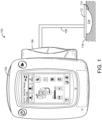
- a negative pressure wound therapy (NPWT) system 100 is shown according to an exemplary embodiment.
- NPWT system 100 is shown to include a therapy device 102 fluidly connected to a wound dressing 112 via a conduit 108.
- Wound dressing 112 may be adhered or sealed to a patient's skin 116 surrounding a wound 115.
- wound dressings 112 which can be used in combination with NPWT system 100 are described in detail in U.S. Patent No. 7,651,484 granted January 26, 2010 , U.S. Patent No. 8,394,081 granted March 12, 2013 , U.S. Patent Application No. 14/087,418 filed November 22, 2013 , and U.S. Provisional Patent Application No. 62/650,132 filed March 29, 2018 .
- Therapy device 102 is configured to provide negative pressure wound therapy by reducing the pressure at wound site 114.
- Therapy device 102 can draw a vacuum at wound site 114 (relative to atmospheric pressure) by removing fluids 107 such as wound exudate, air, and other fluids from wound 115.
- Wound exudate may include fluid that filters from a patient's circulatory system into lesions or areas of inflammation.
- wound exudate may include water and dissolved solutes such as blood, plasma proteins, white blood cells, platelets, and red blood cells.
- Other fluids removed from wound 115 may include instillation fluid previously delivered to wound 115.
- Instillation fluid can include, for example, a cleansing fluid, a prescribed fluid, a medicated fluid, an antibiotic fluid, or any other type of fluid which can be delivered to wound 115 during wound treatment.
- therapy device 102 is configured to deliver instillation fluid to wound 115, as described in U.S. Provisional Patent Application No. 62/650,132 filed March 29, 2018 .
- Fluids 107 removed from wound 115 pass through conduit 108 and are collected in a removed fluid canister 106.
- Conduit 108 may have a first end coupled to canister 106 and a second end coupled to the wound site (e.g., wound dressing 112).
- Canister 106 is a component of therapy device 102 configured to collect wound exudate and other fluids 107 removed from wound 115.
- canister 106 is detachable from therapy device 102 to allow canister 106 to be emptied and replaced as needed.
- a lower portion of canister 106 may be filled with wound exudate and other fluids 107 removed from wound 115, whereas an upper portion of canister 106 may be filled with air.
- Therapy device 102 can be configured to draw a vacuum within canister 106 by pumping air out of canister 106.
- the reduced pressure within canister 106 can be translated to wound dressing 112 and wound 115 via conduit 108 such that wound dressing 112 and wound 115 are maintained at substantially the same pressure as canister 106.
- Therapy device 102 is shown to include a pneumatic pump 120, a relief valve 132, a filter 128, and a controller 118.
- Pump 120 can be fluidly coupled to canister 106 (e.g., via conduit 126) and can be configured to draw a vacuum within canister 106 by pumping air out of canister 106.
- pump 120 is configured to operate in both a forward direction and a reverse direction.
- pump 120 can operate in the forward direction to pump air out of canister 106 and decrease the pressure within canister 106.
- Pump 120 can operate in the reverse direction to pump air into canister 106 and increase the pressure within canister 106.
- Pump 120 can be controlled by controller 118, described in greater detail below.
- Filter 128 can be positioned between canister 106 and pump 120 (e.g., along conduit 126) such that the air pumped out of canister 106 passes through filter 128.
- Filter 128 can be configured to prevent liquid or solid particles from entering conduit 126 and reaching pump 120.
- Filter 128 may include, for example, a bacterial filter that is hydrophobic and/or lipophilic such that aqueous and/or oily liquids will bead on the surface of filter 128.
- Pump 120 can be configured to provide sufficient airflow through filter 128 that the pressure drop across filter 128 is not substantial (e.g., such that the pressure drop will not substantially interfere with the application of negative pressure to wound 115 from therapy device 102).
- Valve 132 can be fluidly connected with pump 120 and filter 128 via conduit 126.
- valve 132 is configured to control airflow between conduit 126 and the environment around therapy device 102.
- valve 132 can be opened to allow airflow into conduit 126, and closed to prevent airflow into conduit 126.
- Valve 132 can be opened and closed by controller 118.
- the negative pressure circuit may include any component of NPWT system 100 that can be maintained at a negative pressure when performing negative pressure wound therapy (e.g., conduit 126, canister 106, conduit 108, wound dressing 112, and/or wound 115).
- therapy device 102 includes a pressure indicator.
- therapy device 102 is shown to include a pressure sensor 130 configured to measure the pressure within canister 106 and/or the pressure at wound dressing 112 or wound 115.
- the therapy device is defined by and includes only a single sensor.
- Pressure measurements recorded by pressure sensor 130 can be communicated to controller 118.
- Controller 118 uses the pressure measurements to ensure that wound 115 is maintained at negative pressure.
- controller 118 can activate pump 120 in response to the pressure measurement from pressure sensor 130 exceeding a negative pressure setpoint in order to reduce the pressure at wound 115.
- controller 118 is shown to include a processor 142 and memory 144.
- Processor 142 may be a general purpose or specific purpose processor, an application specific integrated circuit (ASIC), one or more field programmable gate arrays (FPGAs), a group of processing components, or other suitable processing components.
- Processor 142 is configured to execute computer code or instructions stored in memory 144 or received from other computer readable media (e.g., CDROM, network storage, a remote server, etc.).
- the processor 142 is configured to operate the controller to automatically effectuate the methods of detecting blockages and/or leaks disclosed herein.
- Memory 144 may include one or more devices (e.g., memory units, memory devices, storage devices, etc.) for storing data and/or computer code for completing and/or facilitating the various processes described in the present disclosure.
- Memory 144 may include random access memory (RAM), read-only memory (ROM), hard drive storage, temporary storage, non-volatile memory, flash memory, optical memory, or any other suitable memory for storing software objects and/or computer instructions.
- RAM random access memory
- ROM read-only memory
- ROM read-only memory
- Hard drive storage temporary storage
- non-volatile memory flash memory
- optical memory optical memory
- Memory 144 may include database components, object code components, script components, or any other type of information structure for supporting the various activities and information structures described in the present disclosure.
- Memory 144 may be communicably connected to processor 142 and may include computer code for executing (e.g., by processor 142) one or more processes described herein.
- processor 142 When processor 142 executes instructions stored in memory 144, processor 142 generally configures controller 118 to complete such activities.
- the memory 144 is configured to store the NPWT system monitoring logic 154, which, when executed, is configured to operate the controller to automatically effectuate the methods of detecting blockages and/or leaks disclosed using verification loop 700, leak loop 800, blockage loop 900 and/or issue identification loop 1000 as discussed in more detail below with reference to FIGS. 7-10 .
- the memory 144 additionally stores model pressure decay model data 148 that is used by the NPWT System monitoring logic 154 to detect blockages and/or leaks during operation of the NPWT system 100.
- Controller 118 is shown to include a pump controller 146 and a valve controller 150.
- Pump controller 146 can be configured to operate pump 120 by generating and providing control signals to pump 120.
- the control signals provided to pump 120 can cause pump 120 to activate, deactivate, or achieve a variable capacity or speed (e.g., operate at half speed, operate at full speed, etc.).
- valve controller 150 can be configured to operate valve 132 by generating and providing control signals to valve 132.
- the control signals provided to valve 132 can cause valve 132 to open, close, or achieve a specified intermediate position (e.g., one-third open, half open, etc.).
- NPWT system monitoring logic 154 may utilize the pump controller 146 and/or valve controller 150 are used to effectuate the operation of the pump 120 and/or the opening/closing of the valve 132 during any or all of the verification loop 700, leak loop 800, blockage loop 900 and/or issue identification loop 1000 described herein.
- pump controller 146 uses input from a canister sensor configured to detect whether canister 106 is present. Pump controller 146 can be configured to activate pump 120 only when canister 106 is present. For example, pump controller 146 can check whether canister 106 is present and can activate pump 120 in response to a determination that canister 106 is present. However, if canister 106 is not present, pump controller 146 may prevent pump 120 from activating.
- Controller 118 is shown to include a pressure monitor 152.
- Pressure monitor 152 can be configured to monitor the pressure within canister 106 and/or the pressure within wound dressing 112 or wound site 114 using feedback from pressure sensor 130.
- pressure sensor 130 may provide pressure measurements to pressure monitor 152.
- Pressure monitor 152 can use the pressure measurements to determine the pressure within canister 106 and/or the pressure within wound dressing 112 or wound site 114 in real-time.
- the pressure measurement values relied upon in performing any of the verification loop 700, leak loop 800, blockage loop 900 and/or issue identification loop 1000 may be pressure measurements provided by the pressure monitor 152.
- therapy device 102 includes a data communications interface 124 (e.g., a USB port, a wireless transceiver, etc.) configured to receive and transmit data.
- Communications interface 124 may include wired or wireless communications interfaces (e.g., jacks, antennas, transmitters, receivers, transceivers, wire terminals, etc.) for conducting data communications external systems or devices.
- the communications may be direct (e.g., local wired or wireless communications) or via a communications network (e.g., a WAN, the Internet, a cellular network, etc.).
- communications interface 124 can include a USB port or an Ethernet card and port for sending and receiving data via an Ethernet-based communications link or network.
- communications interface 124 can include a Wi-Fi transceiver for communicating via a wireless communications network or cellular or mobile phone communications transceivers.
- therapy device 102 includes a user interface 148.
- User interface 148 may include one or more buttons, dials, sliders, keys, or other input devices configured to receive input from a user.
- User interface 148 may also include one or more display devices (e.g., LEDs, LCD displays, etc.), speakers, tactile feedback devices, or other output devices configured to provide information to a user.
- the pressure measurements recorded by pressure sensor 130 are presented to a user via user interface 148.
- User interface 148 can also display alerts generated by controller 118.
- alert generator 156 can generate a "blockage detected” and/or a “leakage detected” alert if a blockage is detected within the negative pressure circuit when performing any of the verification loop 700, leak loop 800, blockage loop 900 and/or issue identification loop 1000 using the NPWT system monitoring logic 154.
- valve 132 is closed and pump 120 is operated to draw a vacuum within the negative pressure circuit by causing airflow through filter 128 in a first direction (such as, e.g., illustrated by the arrows of FIG. 2 ).
- a first direction such as, e.g., illustrated by the arrows of FIG. 2 .
- the negative pressure circuit fluidly couples the wound site 114 to the canister 106, causing air to be removed from the wound site 114 and thus allowing a vacuum to be drawn at the wound site 114.
- the negative pressure at the wound site 114 equilibrates to the pressure within the canister 106, such that the pressure at the wound site 114 is substantially the same as the pressure within the canister 106.
- a desired, predetermined pressure may be applied to the wound site 114 by operating the pump 120 until a pressure within the canister 106 is determined to have reached the predetermined negative pressure (as determined, e.g., by a pressure reading obtained by pressure sensor 130).
- the increase of pressure within the negative pressure circuit may be effectuated by opening valve 132 to allow airflow from the environment around therapy device 102 to enter conduit 126 and fill the vacuum within the negative pressure circuit.
- the airflow from conduit 126 into canister 106 and other volumes within the negative pressure circuit may pass through filter 128 in a second direction, opposite the direction, as shown in FIG. 3 .
- the NPWT system 100 system may encounter a number of variables or situations that impair the ability of the NPWT system 100 to maintain a wound site 114 at a target treatment pressure as intended.
- the NPWT system 100 may experience an obstruction, such as, e.g. a blockage 134 occluding an interior of the conduit 108, which may result in the pump 120 failing to draw a vacuum sufficient to achieve the target treatment pressure at the wound site 114.
- the obstruction may also, or alternatively, be caused by a restriction applied to an external portion of the conduit 108 such as, e.g. a kink in the conduit, a clamp applied to the conduit 108 that has been inadvertently left in a closed configuration, etc. and/or a restriction occurring in any other portions of the negative pressure circuit (e.g. wound dressing 112 inlet, canister 106).
- the fluid communication between the canister 106 and the wound site 114, as well as the ability of the pressure at the wound site 114 to equilibrate to the pressure within the canister 106, is prevented or restricted.
- the blockage 134 limits or prevents the flow of air out from the downstream portion of the negative pressure circuit (i.e. the portion of the negative pressure circuit defined between the blockage 134 and the wound site 114).
- the operation of the pump 120 to draw a vacuum may result in a difference between the pressure at the wound site 114 and the pressure within the canister 106. Because the attainment of target treatment pressure within the canister 106 in such a blockage scenario is not necessarily indicative of the pressure at the wound site 114 also being at the target treatment pressure, the operation of the pump 120 based on the monitored pressure within the canister 106 may fail to achieve the target treatment pressure at the wound site 114.
- FIG. 6 another scenario which may impair the ability of the NPWT system 100 to maintain a wound site 114 at a target treatment pressure as intended is illustrated.
- the wound site 114 may initially be subject to the target treatment pressure.
- a leak 136 in the negative pressure circuit through which air from the ambient environment may flow into the negative pressure circuit may prevent the wound site 114 from being maintained at the target treatment pressure for the intended period of time desired for NPWT treatment.
- the increase in pressure within the negative pressure circuit caused by flow of air into the negative pressure circuit through the leak 136 is distinct from, and in addition to, the normal, gradual increase in pressure that normally occurs within the negative pressure circuit as a result of pressure decay.
- the leak 136 may occur in any other components defining the negative pressure circuit (e.g. a hole in the canister 106, a tear in the wound dressing 112, etc.) and/or the connections between any of the components of the negative pressure circuit (e.g. impaired seal between the patient's skin 116 and wound dressing, an improperly attachment between the conduit 108 and canister 106, etc.).
- FIGS. 7-10 methods for monitoring and troubleshooting the operation of the NPWT system 100 are shown according to various embodiments.
- the method described in FIGS. 7-10 allows for detection of a blockage in the NPWT system 100 to include minimal structural components, such as only a single pressure sensor and a single conduit 108 extending between the therapy device 102 and wound dressing 112.
- the various methods described with reference to FIGS. 7-10 below allow the proper operation of the NPWT system 100 to be verified at one or more times prior to or during the use of the NPWT system 100 to provide NPWT treatment.
- the proper operation of the NPWT system 100 as assessed using the one or more processes described with reference to FIGS. 7-10 is based on the comparison of an observed dynamic pressure response within the negative pressure circuit during various points during the operation of the NPWT system 100 to a dynamic pressure response model representative of an expected dynamic pressure response of a properly functioning NPWT system 100 operating under similar conditions.
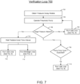
- a flowchart of a verification loop 700 for monitoring and troubleshooting the operation of a wound therapy system is shown, according to an exemplary embodiment.
- a dynamic pressure response of the negative pressure circuit to the purging of the negative pressure circuit is monitored and compared to an expected pressure response to determine whether a blockage and/or leak may be present in the NPWT system 100.
- each pressure decay model represents the dynamic pressure response of a negative pressure circuit defined by a particular set of parameters to a pressure stimulus.
- these pressure decay curves may vary based on various parameters, such as, e.g. an initial pressure within the negative pressure circuit, the volume of the negative pressure circuit, the leak rate of the valve 132, etc.
- the pressure decay models obtained 702 obtained at step 702 desirably include pressure decay models representative of a variety of various volumes, initial pressures, leak rates, etc.
- pressure decay models obtained at step 702 may be obtained from any number of sources.
- the pressure decay models are existing models stored by the memory 144 of the controller 118.
- the pressure decay models are obtained from an external source.
- the pressure decay models may be generated by the NPWT system 100 according to any number of different protocols for generating such dynamic pressure response data.
- the protocols that may be used to generate the pressure decay data at step 702 may be based on the methods disclosed in U.S. Patent Application No. 62/650,132 filed March 29, 2018 , titled WOUND THERAPY SYSTEM WITH WOUND VOLUME ESTIMATION, which is herein incorporated by reference in its entirety.
- the pump 120 is operated to draw a vacuum within the negative pressure circuit so as to attain a desired target pressure within the negative pressure circuit (and in particular, a target pressure desired at the wound site 114).
- the operation of the pump 120 at step 704 may occur immediately following an initial set-up of the NPWT system 100 (e.g. application of the wound dressing 112 to the wound site 114, connection of the conduit 108 to the canister 106, etc.), with the remaining steps of the verification loop 700 being used to verify the proper and correct set-up of the NPWT system 100 prior to an initial use of the NPWT system 100 to provide NPWT treatment.
- the operation of the pump 120 at step 704 may occur at any point during an existing NPWT treatment session using the NPWT system 100.
- the operation of the pump at step 704 may be based on, e.g., a user initiated request to run the verification loop 700, a reoccurring schedule for running the verification loop 700, etc.
- the target pressure may correspond to any desired predetermined pressure, which may be the same or different from a target pressure used when operating the NPWT system 100 to provide NPWT treatment.
- the target pressure will desirably correspond to a target pressure for which pressure decay data has been obtained at step 702.
- the determination of whether the negative pressure circuit is at the target pressure may be determined in any desired manner, such as, e.g., based on a pressure reading of the pressure within the canister 106 obtained by pressure sensor 130.
- a leak loop 800 (as described in more detail below with reference to FIG. 8 ) may optionally be run at step 708 to determine whether the inability to achieve the target pressure within the negative pressure circuit is attributable to a leak in the negative pressure circuit. If such a leak is detected, the leak is repaired, and the pump continues to run at 704 until the target pressure within the negative pressure circuit has been reached.
- the determination at step 706 that the target pressure has not been attained within the negative pressure circuit may be attributable to insufficient time having passed since the initial operation of the pump 120 at step 704. Accordingly, in such a situation, running the leak loop 800 at step 708 may indicate that there is no leak, with the pump continuing to be run at step 704.
- an optional alarm may be generated to the user in the event that the steps of determining that the target has yet to be attained (i.e. step 706) and determining that there is no leak (i.e.
- step 708) have been performed for a predetermined number of cycles, so as to alert the user to one or more possible issues with the NPWT system 100 (such as, e.g., an issue with the operation of the pump, an incorrect target pressure having been entered, etc.) that may be preventing the attainment of the target pressure within the negative pressure circuit.
- one or more possible issues with the NPWT system 100 such as, e.g., an issue with the operation of the pump, an incorrect target pressure having been entered, etc.
- a timer may be initiated at step 710 for a predetermined time interval.
- the timer is set/initiated automatically by the controller 118 in response to the determination at step 706 that the target pressure within the negative pressure circuit has been attained.
- the timer may be set manually by a user.
- one or both of blockage loop 900 (detailed in more description with reference to the FIG. 9 below) and/or leak loop 800 may be run at step 712 and/or step 714, respectively.
- the timer set at step 710 may be a single timer, with the verification loop 700 alternating between running the leak loop 800 and the blockage loop 900 subsequent to the expiration of the timer at step 710 (e.g., after completing blockage loop 900, steps 702-710 are repeated, with the expiration of the timer at step 710 resulting in the leak loop 800 being run).
- the timer set at step 710 may comprise two distinct timers, with the expiration of the first timer resulting in the running of the blockage loop 900 at step 712 and the expiration of the second timer resulting in the running of the leak loop 800 at step 714.
- step 710 of waiting the predetermined time set by the timer may altogether be omitted (or, the timer predetermined time may be set to zero), with the running of the leak loop 800 at step 714 and/or the blockage loop 900 at step 712 being determined based on one or more of, e.g., a user input request to run one or both of the blockage loop 900 and/or leak loop 800, a predetermined schedule based on the overall operation of the NPWT system 100, etc.
- the timer may be set for any desired interval of time at step 710.
- a lower limit of the time interval set by the timer at step 710 corresponds to a minimum time that would be required to detect deviations from expected pressure decay behavior when running the leak loop 800 and/or the blockage loop 900, so as to ensure that any potential leaks and/or blockages of the NPWT system 100 are not missed.
- An upper limit of the time interval set by the timer at step 710 advantageously corresponds to a time interval that is less than the expected time that it would take for the target pressure to decay to ambient pressure based on the data obtained at step 702 for a pressure and volume corresponding to the target pressure and volume of the negative pressure circuit. Additionally, in some embodiments, the upper limit of the time interval may be selected so as to minimize any interference with the use of the NPWT system 100.
- the pump 120 may be configured to periodically be operated to draw an additional vacuum in the negative pressure circuit in an attempt to offset the pressure decay within the negative pressure circuit, and thereby maintain a constant desired treatment pressure at the wound site 114 at a the wound site.
- the greater the rate of pressure decay within the negative pressure circuit the greater the duty cycle of the pump 120 (i.e. the number of times the pump 120 is operated) that will be needed to maintain the constant desired treatment pressure.
- the duty cycle of the pump 120 may be monitored and compared against a threshold duty cycle representative of the frequency with which the pump 120 operates to maintain a constant pressure at the wound site 114 under normal operating conditions.
- a threshold duty cycle representative of the frequency with which the pump 120 operates to maintain a constant pressure at the wound site 114 under normal operating conditions.
- the leak loop 800 may be performed at step 718 to determine whether the determined increased duty cycle may be attributed to a leak in the NPWT system 100.
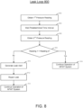
- a leak loop 800 is illustrated.
- the leak loop 800 may be performed any number of times and on either a scheduled or unscheduled basis as desired. Accordingly, in some embodiments the leak loop 800 may be run without first determining whether the pump duty cycle exceeds a threshold at step 716 and/or without being dependent on the expiration of the predetermined time at step 710 of the verification loop 700.
- a first pressure reading of the pressure within the negative pressure circuit is obtained.
- the determination of pressure within the negative pressure circuit may be determined in any desired manner, such as, e.g., based on a pressure reading of the pressure within the canister 106 obtained by pressure sensor 130.
- the leak loop 800 may be initiated concurrent with the operation of the pump 120 to attain the desired target pressure within the negative pressure circuit, in which case the pressure reading obtained at step 802 would correspond to the target pressure attained within the negative pressure circuit.
- the first pressure reading obtained at step 802 may correspond to the target pressure has been attained at step 704 of the verification loop 700.
- a leak timer is set.
- the timer may be set for any desired interval of time.
- a lower limit of the time interval set by the timer corresponds to a minimum time that would be sufficient to detect deviations from expected pressure decay behavior when running the leak loop 800, so as to ensure that the effects of any potential leaks in the NPWT system 100 on the pressure decay within the negative pressure circuit are not missed.
- An upper limit of the time interval set by the timer advantageously corresponds to a time interval that is less than the expected time that it would take for a pressure corresponding to the first pressure reading obtained at step 802 to decay to ambient pressure based on the data obtained at step 702 for a pressure and volume corresponding to the target pressure and volume of the negative pressure circuit.
- the upper limit of the time interval may be selected so as to minimize any interference with the use of the NPWT system 100.
- a second pressure reading of the pressure within the negative pressure circuit is obtained at step 806.
- the first pressure reading obtained at step 802 is compared to the second pressure reading obtained at step 806.
- a leak alert is generated in response to the determination at step 808 that the two readings are not substantially the same as one another.
- the leak may be repaired, following which at step 814 operation of the NPWT system 100 is continued. Alternatively, if the two readings are determined to be substantially the same as another at step 808, at step 816, operation of the NPWT system 100 may be continued.
- the first and second pressure readings may be determined to be substantially the same as one another at step 808 if the difference between the first pressure reading obtained at step 802 and the second pressure reading obtained at step 806 is between approximately 0 percent and approximately ⁇ 15 percent, and more specifically between approximately 0 percent and approximately ⁇ 5 percent.
- other suitable ranges may be used in defining the first pressure reading obtained at step 802 and the second pressure reading obtained at step 806 as being substantially similar to one another.
- the suitable range for the difference by which it is determined at step 808 if the first pressure reading obtained at step 802 and the second pressure reading obtained at step 806 are substantially similar may be based on the time interval set at step 804. In some such embodiments, the suitable range used at step 808 may be greater in embodiments in which a greater time interval is waited at step 804.
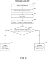
- a target pressure is attained within the negative pressure circuit.
- the target pressure attained at step 902 may be any desired pressure, which may be the same or different from the target pressure that is used during used of the NPWT system 100 to provide NPWT treatment.
- the target pressure may have been previously attained prior to the commencement of the blockage loop 900, in which situation step 902 is omitted.
- a timer is set for a predetermined time interval.
- the time period that is allowed to elapse at step 904 may be the same as the time interval waited at step 710 of the verification loop 700, or may be in addition to the time interval waited at step 710 of the verification loop 700.
- the considerations relevant to the selection of the time interval may be similar to those used in the selection of a time interval that have been described previously, e.g., with reference to the selection of a time interval at step 710 of the verification loop 700.
- the valve 132 Upon the expiration of the time interval at step 904, the valve 132 is opened at step 906 to allow air from the ambient environment to flow into the negative pressure circuit.
- any other number of manners of purging the negative pressure circuit in a controlled manner i.e. in which the rate of flow of air into the negative pressure circuit may reliably be accounted for
- the valve 132 may be defined by a calibrated leak that allows for a controlled rate of air to flow into the negative pressure circuit to equilibrate the negative pressure within the negative pressure circuit.
- the valve 132 may comprise one or more calibrated leaks.
- the valve 132 is shown in FIGS. 1-3 as being defined within the therapy device 102, according to other embodiments, the valve 132 may alternatively, or additionally, be provided by the canister 106 and/or the conduit 108.
- the dynamic pressure response to the opening of the valve 132 at step 906 is monitored at step 908.
- the monitoring of the increasing pressure within the negative pressure circuit at step 908 may be performed in any number of manners, including, e.g. monitoring the changes in pressure within the canister 106 as measured by pressure sensor 130.
- the monitoring of the pressure decay within the negative pressure circuit at step 908 continues until it has been determined (e.g., via the measurement of pressure within the canister 106 using pressure sensor 130) that the pressure within the removed fluid circuit has reached a predetermined threshold pressure, such as, e.g. a pressure equal to that of the ambient environment.
- the predetermined threshold pressure may be any pressure that is greater (i.e. less negative) that an initial target pressure attained within the negative pressure circuit prior to the opening of the valve at step 902.
- the pressure decay within the negative pressure circuit as observed during step 908 is compared against model pressure decay data obtained at step 704 for a model decay curve that corresponds to the parameters defining the negative pressure circuit (e.g. initial target pressure within the negative pressure loop, the volume of the negative pressure loop, the size/rate of flow ratings of the valve, the length of time during which the valve was opened, etc.) to determine whether the observed pressure decay at step 908 is substantially the same as the expected pressure decay based on the model pressure decay data.
- observed pressure decay at step 908 may be determined to be substantially the same as the expected data if the difference between the measured and expected pressure decay is between approximately 0 percent and approximately ⁇ 15 percent, and more specifically between approximately 0 percent and approximately ⁇ 5 percent.
- step 910 If it is determined at step 910 that the pressure decay observed at step 908 is substantially similar to the expected pressure decay, at step 912 the NPWT system 100 is identified as operating as intended, and the operation of the NPWT system 100 may be continued as originally intended. In contrast, if it is determined at step 910 that the pressure decay observed at step 908 is not substantially similar to the expected pressure decay, at step 914, an issue identification loop 1000 may be run to identify the source of the discrepancy between the observed pressure decay at step 908 with expected pressure decay determined at step 910.
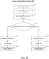
- an issue identification loop 1000 according to one embodiment is illustrated.
- the determination at step 910 that the observed pressure decay of step 908 is not substantially similar to the expected pressure decay may be sufficient to alert a user to an issue with the NPWT system 100, this determination alone may not be enough to allow the user to easily determine the underlying source of the issue with the NPWT system 100.
- the pump 120 is operated to apply the same target pressure to the negative pressure circuit as was applied to the negative pressure circuit during step 902 of the blockage loop (which, if the issue identification is being run in response to the running of the verification loop 700 of FIG. 7 , is the same target pressure applied to the negative pressure circuit at step 704).
- the predetermined time waited at step 904 or, if the issue identification loop 1000 is being run in response to the running of the verification loop 700 of FIG. 7 , the time interval waited at step 710) following the attainment of the target pressure within the negative pressure circuit, at step 1004, the valve is opened 128 immediately following the target pressure being reaching within the negative pressure circuit.
- the opening of the valve 132 at step 1004 (or the purging of the negative pressure circuit using other means) is carried out in a manner identical (e.g. same degree of opening of the valve 132, same duration of time for which the valve 132 is opened, etc.) to the manner in which the valve 132 or other purge mechanism was operated at step 906 of the blockage loop 900.
- the dynamic pressure response in response to the opening of the valve 132 at step 1004 is monitored as the pressure within the negative pressure circuit increases to the threshold pressure (e.g. ambient pressure).
- the monitoring of the increasing pressure within the negative pressure circuit at step 1006 may be performed in any number of manners, including, e.g. monitoring the changes in pressure within the canister 106 as measured by pressure sensor 130.
- the monitoring of the pressure decay within the negative pressure circuit at step 1006 continues until it has been determined (e.g., via the measurement of pressure within the canister 106 using pressure sensor 130) that the pressure within the removed fluid circuit has reached a predetermined threshold pressure that is the same as the predetermined threshold pressure reached at step 908 of the blockage loop 900.
- the dynamic pressure response observed at step 1006 is compared to the dynamic pressure response observed at step 908 to determine whether the second pressure decay reading obtained at step 1006 is substantially the same as the first pressure decay reading obtained at step 908 of the blockage loop 900.
- the first reading and second reading may be considered substantially similar to one another at step 1008 if the dynamic pressure response observed at step 1006 and the dynamic pressure response observed at step 908 are determined to be between 0 percent and approximately ⁇ 15 percent, and more specifically between approximately 0 percent and approximately ⁇ 5 percent of one another.
- other suitable ranges may be used in defining the dynamic pressure response observed at step 1006 and the dynamic pressure response observed at step 908 as being substantially similar to one another.
- the determination of whether the two reading are substantially the same at step 1008 may in some arrangements vary based on the time interval set with the timer at step 904 of the blockage loop 900 (which, as noted above, in some embodiments in which the blockage loop 900 is being performed at step 712 of the verification loop 700 may be equal to the time interval waited at step 710).
- the acceptable degree of difference and/or an acceptable absolute difference between the first dynamic pressure response observed at step 908 and the second dynamic pressure response observed at step 1006 that would be considered as being substantially similar at step 1008 may additionally, or alternatively, be based on the time interval waited at step 904 of the blockage loop 900.
- a blockage alarm is generated in response to a determination at step 1008 that the dynamic pressure response obtained at step 1008 is substantially the same as the dynamic pressure response obtained at step 908.
- a blockage 134 in the negative pressure circuit reduces the effective volume of the negative pressure circuit. Because smaller volumes (e.g., a negative pressure circuit with a blockage 134) require less time to be purged of negative pressure than larger volumes (e.g., the same negative pressure circuit without the blockage), a negative pressure circuit with a blockage would be expected to exhibit a different pressure decay curve that varies (i.e. one that reaches the predetermined threshold pressure in a lesser time) from a pressure decay curve of a negative pressure circuit without a blockage under similar conditions.
- the pressure decay curves of negative pressure circuits having the same volume and subject to the same initial target pressure would be substantially similar to one another, irrespective of the amount of time that may have passed between the attainment of the target pressure within negative pressure circuit and the purging of the negative pressure circuit.
- the blockage may be cleared, following which, at step 1014, normal operation of the NPWT system 100 may resume.
- a leak alarm is generated in response to a determination at step 1008 that the dynamic pressure response observed at step 1008 is not substantially the same as the dynamic pressure response observed at step 908.
- air that is introduced into the negative pressure circuit through the leak 136 results in the pressure in the negative circuit decaying (i.e. becoming more positive) at a faster rate than would be expected under normal operating conditions, with the pressure within the negative pressure circuit increasing as more air is introduced into the negative pressure circuit through the leak 136.
- the longer the time waited between the attainment of a target pressure within the negative pressure circuit and the purging of the negative pressure circuit the lower the pressure within the negative circuit will be at the point at which the valve 132 is opened to purge the negative pressure circuit.
- the dynamic pressure response within the negative pressure observed following the opening of the valve 132 in a situation in which a predetermined period of time was allowed to pass between the attainment of the target pressure and the purging of the negative pressure circuit will vary from the dynamic pressure response within the negative pressure observed following the opening of the valve 132 in a situation in which the purging of the negative pressure circuit occurred immediately after (or in less time than the predetermined time) following the attainment of the target pressure.
- the leak may be repaired, following which at step 1020 normal operation of the NPWT system 100 may resume.
- a blockage 134 in the negative pressure circuit may become dislodged by itself during the steps of drawing a vacuum in the negative pressure circuit and/or purging the negative pressure within the negative pressure circuit.
- a discrepancy between the observed dynamic pressure responses during the blockage loop 900 and/or issue identification loop 1000 may be determined at step 1008 as not being substantially similar to one another. Accordingly, in some embodiments, prior to generating the leak alarm at step 1016 and/or in the event that a leak cannot be found during step 1018, the blockage loop 900 and/or issue identification loop 1000 may be repeated to verify whether the initial discrepancy between the two observed dynamic pressure response determined at step 1008 has been resolved by itself.
- the verification loop 700, leak loop 800, blockage loop 900 and/or issue identification loop 1000 described with reference to FIGS. 7-10 may optionally be used with other existing wound therapy systems, allowing such existing NPWT therapy devices formed without blockage and/or leak detecting capabilities to be provided with such capabilities without requiring and physical reconfiguration and/or modification to do so.
- the present disclosure contemplates methods, systems and program products on any machine-readable media for accomplishing various operations.
- the embodiments of the present disclosure can be implemented using existing computer processors, or by a special purpose computer processor for an appropriate system, incorporated for this or another purpose, or by a hardwired system
- Embodiments within the scope of the present disclosure include program products comprising machine-readable media for carrying or having machine-executable instructions or data structures stored thereon.
- Such machine-readable media can be any available media that can be accessed by a general purpose or special purpose computer or other machine with a processor.
- machine-readable media can comprise RAM, ROM, EPROM, EEPROM, CD-ROM or other optical disk storage, magnetic disk storage or other magnetic storage devices, or any other medium which can be used to carry or store desired program code in the form of machine-executable instructions or data structures and which can be accessed by a general purpose or special purpose computer or other machine with a processor. Combinations of the above are also included within the scope of machine-readable media.
- Machine-executable instructions include, for example, instructions and data which cause a general purpose computer, special purpose computer, or special purpose processing machines to perform a certain function or group of functions.
Landscapes
- Health & Medical Sciences (AREA)
- Heart & Thoracic Surgery (AREA)
- Hematology (AREA)
- Engineering & Computer Science (AREA)
- Anesthesiology (AREA)
- Biomedical Technology (AREA)
- Vascular Medicine (AREA)
- Life Sciences & Earth Sciences (AREA)
- Animal Behavior & Ethology (AREA)
- General Health & Medical Sciences (AREA)
- Public Health (AREA)
- Veterinary Medicine (AREA)
- Media Introduction/Drainage Providing Device (AREA)
- External Artificial Organs (AREA)
Claims (13)
- Système de traitement des plaies, comprenant :une boîte (106) conçue pour contenir le fluide prélevé sur le site d'une plaie ;un conduit (108) ayant une première extrémité accouplée à la boîte (106) et une seconde extrémité accouplée de manière opérationnelle au site de la plaie ;dans lequel un volume intérieur de la boîte (106) et un volume intérieur du conduit (108) définissent un circuit de pression négative ;une pompe (120) accouplée de manière opérationnelle et fluidique au site de la plaie par l'intermédiaire du conduit (108) et conçue pour appliquer une pression négative au site de la plaie par l'intermédiaire du circuit de pression négative ;un indicateur de pression conçu pour indiquer une pression à l'intérieur du circuit de pression négative ; etun dispositif de commande (118) configuré pour :stocker (702) une courbe de décroissance de la pression de base représentative d'un changement de pression à l'intérieur du circuit de pression négative d'une première pression négative à une pression seuil prédéterminée sur un premier laps de temps ;générer une deuxième courbe de décroissance de la pression en faisant fonctionner (902) la pompe (120) pour appliquer une deuxième pression négative égale à la première pression négative au circuit de pression négative et en mesurant (908) un changement de pression sur un deuxième laps de temps à l'intérieur du circuit de pression négative au cours duquel la pression à l'intérieur du circuit de pression négative augmente de la deuxième pression négative appliquée à la pression seuil ;comparer (910) la deuxième courbe de décroissance de la pression à la courbe de décroissance de la pression de base : etgénérer une alerte en réponse à la détection qu'une différence entre la deuxième courbe de décroissance de la pression et la courbe de décroissance de la pression de base dépasse un premier seuil de variance prédéterminé ;caractérisé en ce que, en réponse à la génération de l'alerte, le dispositif de commande est en outre configuré pour :générer une troisième courbe de décroissance de la pression en faisant fonctionner (1002) la pompe (120) pour appliquer une troisième pression négative égale à la première pression négative au circuit de pression négative et en mesurant (1006) un changement de pression sur un troisième laps de temps à l'intérieur du circuit de pression négative au cours duquel la pression à l'intérieur du circuit de pression négative augmente de la troisième pression négative appliquée à la pression seuil ; etcomparer (1008) la troisième courbe de décroissance de la pression à la deuxième courbe de décroissance de la pression ;le dispositif de commande (118) est en outre configuré pour générer une alarme de blocage (1010) en réponse à la détection que la troisième courbe de décroissance de la pression est sensiblement la même que la deuxième courbe de décroissance de la pression ; etle dispositif de commande (118) est en outre configuré pour générer une alarme de fuite (1016) en réponse à la détection qu'une différence entre la troisième courbe de décroissance de la pression et la deuxième courbe de décroissance de la pression dépasse un second seuil de variance prédéterminé.
- Système de traitement des plaies selon la revendication 1, dans lequel, en réponse à la détection que la deuxième courbe de décroissance de la pression est sensiblement la même que la courbe de décroissance de la pression de base, le dispositif de commande (118) est en outre configuré pour, à la suite d'un intervalle de temps prédéterminé :générer une troisième courbe de décroissance de la pression en faisant fonctionner la pompe pour appliquer une troisième pression négative égale à la première pression négative au circuit de pression négative et en mesurant un changement de pression sur un troisième laps de temps à l'intérieur du circuit de pression négative au cours duquel la pression à l'intérieur du circuit de pression négative augmente de la troisième pression négative appliquée à la pression seuil ; etcomparer la troisième courbe de décroissance de la pression à la courbe de décroissance de la pression de base.
- Système de traitement des plaies selon la revendication 1, dans lequel la courbe de décroissance de la pression de base stockée par le dispositif de commande (118) est générée en fonction de la mesure de la décroissance de la pression à l'intérieur du circuit de pression négative avant une utilisation initiale du système de traitement des plaies pour fournir une thérapie par pression négative au site de la plaie.
- Système de traitement des plaies selon la revendication 1, comprenant en outre une fuite calibrée en communication fluidique avec le circuit de pression négative, la fuite calibrée étant conçue pour permettre à l'air ambiant de s'écouler dans le circuit de pression négative à un débit connu et d'augmenter la pression à l'intérieur du circuit de pression négative.
- Système de traitement des plaies selon la revendication 1, dans lequel la différence détectée entre la deuxième courbe de décroissance de la pression et la courbe de décroissance de la pression de base comprend au moins l'une parmi une différence entre une pente de la courbe de décroissance de la pression de base et une pente de la deuxième courbe de décroissance de la pression et une différence entre le premier laps de temps et le deuxième laps de temps.
- Système de traitement des plaies selon la revendication 5, dans lequel le premier seuil de variance est compris entre approximativement 5 % et approximativement 15 %.
- Système de traitement des plaies selon la revendication 1 ou selon la revendication 6, dans lequel la différence détectée entre la troisième courbe de décroissance de la pression et la deuxième courbe de décroissance de la pression comprend au moins l'une parmi une différence entre une pente de la troisième courbe de décroissance de la pression et une pente de la deuxième courbe de décroissance de la pression et une différence entre le troisième laps de temps et le deuxième laps de temps.
- Système de traitement des plaies selon la revendication 7, dans lequel le second seuil de variance est compris entre approximativement 5 % et approximativement 15 %.
- Système de traitement des plaies selon la revendication 1, dans lequel le volume intérieur du conduit est défini par une seule lumière.
- Système de traitement des plaies selon la revendication 9, dans lequel le conduit (108) définit le seul chemin de fluide entre la boîte et le site de la plaie.
- Système de traitement des plaies selon la revendication 1, dans lequel la courbe de décroissance de la pression de base stockée par le dispositif de commande (118) comprend une pluralité de courbes de décroissance de la pression de base spécifiques au volume, chacune des courbes de décroissance de la pression de base spécifiques au volume étant représentative d'un changement de pression à l'intérieur d'un circuit de pression négative défini par un volume spécifique ;
le dispositif de commande (118) étant en outre configuré pour déterminer un volume du circuit de pression négative, dans lequel la courbe de décroissance de la pression de base à laquelle la deuxième courbe de décroissance est comparée comprend une courbe de décroissance de la pression de base spécifique au volume correspondant au volume déterminé du circuit de pression négative. - Système de traitement des plaies selon la revendication 11, dans lequel le volume du circuit de pression négative est déterminé en fonction d'une identification par le dispositif de commande (118) du volume intérieur de la boîte (106).
- Système de traitement des plaies selon la revendication 12, dans lequel le volume du circuit de pression négative est en outre déterminé en fonction d'une identification par le dispositif de commande (118) d'une quantité de fluide qui a été instillée dans le site de la plaie.
Applications Claiming Priority (2)
| Application Number | Priority Date | Filing Date | Title |
|---|---|---|---|
| US201862767177P | 2018-11-14 | 2018-11-14 | |
| PCT/US2019/060590 WO2020102035A1 (fr) | 2018-11-14 | 2019-11-08 | Système de thérapie de plaies comprenant une détection de blocage et de fuite |
Publications (2)
| Publication Number | Publication Date |
|---|---|
| EP3880268A1 EP3880268A1 (fr) | 2021-09-22 |
| EP3880268B1 true EP3880268B1 (fr) | 2024-09-11 |
Family
ID=69160161
Family Applications (1)
| Application Number | Title | Priority Date | Filing Date |
|---|---|---|---|
| EP19836126.3A Active EP3880268B1 (fr) | 2018-11-14 | 2019-11-08 | Système de thérapie de plaies comprenant une détection de blocage et de fuite |
Country Status (3)
| Country | Link |
|---|---|
| US (1) | US12653940B2 (fr) |
| EP (1) | EP3880268B1 (fr) |
| WO (1) | WO2020102035A1 (fr) |
Families Citing this family (6)
| Publication number | Priority date | Publication date | Assignee | Title |
|---|---|---|---|---|
| GB202004181D0 (en) | 2020-03-23 | 2020-05-06 | Smith & Nephew | Self-tesing for negative pressure wound therapy devices |
| GB202005928D0 (en) | 2020-04-23 | 2020-06-10 | Smith & Nephew | Dual mode negative pressure source operation for provision of negative pressure wound therapy |
| US12582763B2 (en) | 2021-04-21 | 2026-03-24 | T.J.Smith And Nephew, Limited | Communication systems and methods for negative pressure wound therapy devices |
| USD1099288S1 (en) | 2022-03-23 | 2025-10-21 | T.J. Smith And Nephew, Limited | Device for applying negative pressure to a wound |
| AU2024360598A1 (en) * | 2023-10-10 | 2026-04-23 | International Medical Research Pty Ltd | Wound drainage pressure maintenance |
| EP4717283A1 (fr) * | 2024-09-25 | 2026-04-01 | Mölnlycke Health Care AB | Traitement de plaies par pression négative |
Family Cites Families (136)
| Publication number | Priority date | Publication date | Assignee | Title |
|---|---|---|---|---|
| US1355846A (en) | 1920-02-06 | 1920-10-19 | David A Rannells | Medical appliance |
| US2547758A (en) | 1949-01-05 | 1951-04-03 | Wilmer B Keeling | Instrument for treating the male urethra |
| US2632443A (en) | 1949-04-18 | 1953-03-24 | Eleanor P Lesher | Surgical dressing |
| GB692578A (en) | 1949-09-13 | 1953-06-10 | Minnesota Mining & Mfg | Improvements in or relating to drape sheets for surgical use |
| US2682873A (en) | 1952-07-30 | 1954-07-06 | Johnson & Johnson | General purpose protective dressing |
| NL189176B (nl) | 1956-07-13 | 1900-01-01 | Hisamitsu Pharmaceutical Co | Pleister op basis van een synthetische rubber. |
| US2969057A (en) | 1957-11-04 | 1961-01-24 | Brady Co W H | Nematodic swab |
| US3066672A (en) | 1960-09-27 | 1962-12-04 | Jr William H Crosby | Method and apparatus for serial sampling of intestinal juice |
| US3367332A (en) | 1965-08-27 | 1968-02-06 | Gen Electric | Product and process for establishing a sterile area of skin |
| US3520300A (en) | 1967-03-15 | 1970-07-14 | Amp Inc | Surgical sponge and suction device |
| US3568675A (en) | 1968-08-30 | 1971-03-09 | Clyde B Harvey | Fistula and penetrating wound dressing |
| US3682180A (en) | 1970-06-08 | 1972-08-08 | Coilform Co Inc | Drain clip for surgical drain |
| BE789293Q (fr) | 1970-12-07 | 1973-01-15 | Parke Davis & Co | Pansement medico-chirugical pour brulures et lesions analogues |
| US3826254A (en) | 1973-02-26 | 1974-07-30 | Verco Ind | Needle or catheter retaining appliance |
| DE2527706A1 (de) | 1975-06-21 | 1976-12-30 | Hanfried Dr Med Weigand | Einrichtung zum einleiten von kontrastmittel in einen kuenstlichen darmausgang |
| DE2640413C3 (de) | 1976-09-08 | 1980-03-27 | Richard Wolf Gmbh, 7134 Knittlingen | Katheter-Überwachungsgerät |
| NL7710909A (nl) | 1976-10-08 | 1978-04-11 | Smith & Nephew | Samengestelde hechtstrook. |
| GB1562244A (en) | 1976-11-11 | 1980-03-05 | Lock P M | Wound dressing materials |
| US4080970A (en) | 1976-11-17 | 1978-03-28 | Miller Thomas J | Post-operative combination dressing and internal drain tube with external shield and tube connector |
| US4139004A (en) | 1977-02-17 | 1979-02-13 | Gonzalez Jr Harry | Bandage apparatus for treating burns |
| US4184510A (en) | 1977-03-15 | 1980-01-22 | Fibra-Sonics, Inc. | Valued device for controlling vacuum in surgery |
| US4165748A (en) | 1977-11-07 | 1979-08-28 | Johnson Melissa C | Catheter tube holder |
| US4245637A (en) | 1978-07-10 | 1981-01-20 | Nichols Robert L | Shutoff valve sleeve |
| SE414994B (sv) | 1978-11-28 | 1980-09-01 | Landstingens Inkopscentral | Venkateterforband |
| GB2047543B (en) | 1978-12-06 | 1983-04-20 | Svedman Paul | Device for treating tissues for example skin |
| US4266545A (en) | 1979-04-06 | 1981-05-12 | Moss James P | Portable suction device for collecting fluids from a closed wound |
| US4284079A (en) | 1979-06-28 | 1981-08-18 | Adair Edwin Lloyd | Method for applying a male incontinence device |
| US4261363A (en) | 1979-11-09 | 1981-04-14 | C. R. Bard, Inc. | Retention clips for body fluid drains |
| US4569348A (en) | 1980-02-22 | 1986-02-11 | Velcro Usa Inc. | Catheter tube holder strap |
| US4480638A (en) | 1980-03-11 | 1984-11-06 | Eduard Schmid | Cushion for holding an element of grafted skin |
| US4297995A (en) | 1980-06-03 | 1981-11-03 | Key Pharmaceuticals, Inc. | Bandage containing attachment post |
| US4333468A (en) | 1980-08-18 | 1982-06-08 | Geist Robert W | Mesentery tube holder apparatus |
| US4465485A (en) | 1981-03-06 | 1984-08-14 | Becton, Dickinson And Company | Suction canister with unitary shut-off valve and filter features |
| US4392853A (en) | 1981-03-16 | 1983-07-12 | Rudolph Muto | Sterile assembly for protecting and fastening an indwelling device |
| US4373519A (en) | 1981-06-26 | 1983-02-15 | Minnesota Mining And Manufacturing Company | Composite wound dressing |
| US4392858A (en) | 1981-07-16 | 1983-07-12 | Sherwood Medical Company | Wound drainage device |
| US4419097A (en) | 1981-07-31 | 1983-12-06 | Rexar Industries, Inc. | Attachment for catheter tube |
| AU550575B2 (en) | 1981-08-07 | 1986-03-27 | Richard Christian Wright | Wound drainage device |
| SE429197B (sv) | 1981-10-14 | 1983-08-22 | Frese Nielsen | Anordning for behandling av sar |
| DE3146266A1 (de) | 1981-11-21 | 1983-06-01 | B. Braun Melsungen Ag, 3508 Melsungen | Kombinierte vorrichtung fuer eine medizinische saugdrainage |
| US4551139A (en) | 1982-02-08 | 1985-11-05 | Marion Laboratories, Inc. | Method and apparatus for burn wound treatment |
| US4475909A (en) | 1982-05-06 | 1984-10-09 | Eisenberg Melvin I | Male urinary device and method for applying the device |
| DE3361779D1 (en) | 1982-07-06 | 1986-02-20 | Dow Corning | Medical-surgical dressing and a process for the production thereof |
| NZ206837A (en) | 1983-01-27 | 1986-08-08 | Johnson & Johnson Prod Inc | Thin film adhesive dressing:backing material in three sections |
| US4548202A (en) | 1983-06-20 | 1985-10-22 | Ethicon, Inc. | Mesh tissue fasteners |
| US4540412A (en) | 1983-07-14 | 1985-09-10 | The Kendall Company | Device for moist heat therapy |
| US4543100A (en) | 1983-11-01 | 1985-09-24 | Brodsky Stuart A | Catheter and drain tube retainer |
| US4525374A (en) | 1984-02-27 | 1985-06-25 | Manresa, Inc. | Treating hydrophobic filters to render them hydrophilic |
| CA1286177C (fr) | 1984-05-03 | 1991-07-16 | Smith And Nephew Associated Companies Plc | Pansement adhesif |
| US4897081A (en) | 1984-05-25 | 1990-01-30 | Thermedics Inc. | Percutaneous access device |
| US5215522A (en) | 1984-07-23 | 1993-06-01 | Ballard Medical Products | Single use medical aspirating device and method |
| GB8419745D0 (en) | 1984-08-02 | 1984-09-05 | Smith & Nephew Ass | Wound dressing |
| US4872450A (en) | 1984-08-17 | 1989-10-10 | Austad Eric D | Wound dressing and method of forming same |
| US4655754A (en) | 1984-11-09 | 1987-04-07 | Stryker Corporation | Vacuum wound drainage system and lipids baffle therefor |
| US4826494A (en) | 1984-11-09 | 1989-05-02 | Stryker Corporation | Vacuum wound drainage system |
| US4605399A (en) | 1984-12-04 | 1986-08-12 | Complex, Inc. | Transdermal infusion device |
| US5037397A (en) | 1985-05-03 | 1991-08-06 | Medical Distributors, Inc. | Universal clamp |
| US4640688A (en) | 1985-08-23 | 1987-02-03 | Mentor Corporation | Urine collection catheter |
| US4710165A (en) | 1985-09-16 | 1987-12-01 | Mcneil Charles B | Wearable, variable rate suction/collection device |
| US4758220A (en) | 1985-09-26 | 1988-07-19 | Alcon Laboratories, Inc. | Surgical cassette proximity sensing and latching apparatus |
| US4733659A (en) | 1986-01-17 | 1988-03-29 | Seton Company | Foam bandage |
| WO1987004626A1 (fr) | 1986-01-31 | 1987-08-13 | Osmond, Roger, L., W. | Systeme de succion pour drainage de blessures et drainage gastro-intestinal |
| US4838883A (en) | 1986-03-07 | 1989-06-13 | Nissho Corporation | Urine-collecting device |
| JPS62281965A (ja) | 1986-05-29 | 1987-12-07 | テルモ株式会社 | カテ−テルおよびカテ−テル用固定部材 |
| GB8621884D0 (en) | 1986-09-11 | 1986-10-15 | Bard Ltd | Catheter applicator |
| GB2195255B (en) | 1986-09-30 | 1991-05-01 | Vacutec Uk Limited | Apparatus for vacuum treatment of an epidermal surface |
| US4743232A (en) | 1986-10-06 | 1988-05-10 | The Clinipad Corporation | Package assembly for plastic film bandage |
| DE3634569A1 (de) | 1986-10-10 | 1988-04-21 | Sachse Hans E | Kondomkatheter, ein harnroehrenkatheter zur verhinderung von aufsteigenden infektionen |
| JPS63135179A (ja) | 1986-11-26 | 1988-06-07 | 立花 俊郎 | 薬物の経皮投与具 |
| GB8628564D0 (en) | 1986-11-28 | 1987-01-07 | Smiths Industries Plc | Anti-foaming agent suction apparatus |
| GB8706116D0 (en) | 1987-03-14 | 1987-04-15 | Smith & Nephew Ass | Adhesive dressings |
| US4787888A (en) | 1987-06-01 | 1988-11-29 | University Of Connecticut | Disposable piezoelectric polymer bandage for percutaneous delivery of drugs and method for such percutaneous delivery (a) |
| US4863449A (en) | 1987-07-06 | 1989-09-05 | Hollister Incorporated | Adhesive-lined elastic condom cathether |
| US5176663A (en) | 1987-12-02 | 1993-01-05 | Pal Svedman | Dressing having pad with compressibility limiting elements |
| US4906240A (en) | 1988-02-01 | 1990-03-06 | Matrix Medica, Inc. | Adhesive-faced porous absorbent sheet and method of making same |
| US4985019A (en) | 1988-03-11 | 1991-01-15 | Michelson Gary K | X-ray marker |
| GB8812803D0 (en) | 1988-05-28 | 1988-06-29 | Smiths Industries Plc | Medico-surgical containers |
| US4919654A (en) | 1988-08-03 | 1990-04-24 | Kalt Medical Corporation | IV clamp with membrane |
| US5000741A (en) | 1988-08-22 | 1991-03-19 | Kalt Medical Corporation | Transparent tracheostomy tube dressing |
| US5059596A (en) | 1989-01-16 | 1991-10-22 | Roussel Uclaf | Azabicyclo compounds |
| GB8906100D0 (en) | 1989-03-16 | 1989-04-26 | Smith & Nephew | Laminates |
| US5100396A (en) | 1989-04-03 | 1992-03-31 | Zamierowski David S | Fluidic connection system and method |
| US5261893A (en) | 1989-04-03 | 1993-11-16 | Zamierowski David S | Fastening system and method |
| US4969880A (en) | 1989-04-03 | 1990-11-13 | Zamierowski David S | Wound dressing and treatment method |
| US5527293A (en) | 1989-04-03 | 1996-06-18 | Kinetic Concepts, Inc. | Fastening system and method |
| JP2719671B2 (ja) | 1989-07-11 | 1998-02-25 | 日本ゼオン株式会社 | 創傷被覆材 |
| US5358494A (en) | 1989-07-11 | 1994-10-25 | Svedman Paul | Irrigation dressing |
| US5232453A (en) | 1989-07-14 | 1993-08-03 | E. R. Squibb & Sons, Inc. | Catheter holder |
| GB2235877A (en) | 1989-09-18 | 1991-03-20 | Antonio Talluri | Closed wound suction apparatus |
| US5134994A (en) | 1990-02-12 | 1992-08-04 | Say Sam L | Field aspirator in a soft pack with externally mounted container |
| US5092858A (en) | 1990-03-20 | 1992-03-03 | Becton, Dickinson And Company | Liquid gelling agent distributor device |
| US5149331A (en) | 1991-05-03 | 1992-09-22 | Ariel Ferdman | Method and device for wound closure |
| US5278100A (en) | 1991-11-08 | 1994-01-11 | Micron Technology, Inc. | Chemical vapor deposition technique for depositing titanium silicide on semiconductor wafers |
| US5645081A (en) | 1991-11-14 | 1997-07-08 | Wake Forest University | Method of treating tissue damage and apparatus for same |
| US5636643A (en) | 1991-11-14 | 1997-06-10 | Wake Forest University | Wound treatment employing reduced pressure |
| US5279550A (en) | 1991-12-19 | 1994-01-18 | Gish Biomedical, Inc. | Orthopedic autotransfusion system |
| US5167613A (en) | 1992-03-23 | 1992-12-01 | The Kendall Company | Composite vented wound dressing |
| FR2690617B1 (fr) | 1992-04-29 | 1994-06-24 | Cbh Textile | Pansement adhesif transparent. |
| DE4306478A1 (de) | 1993-03-02 | 1994-09-08 | Wolfgang Dr Wagner | Drainagevorrichtung, insbesondere Pleuradrainagevorrichtung, und Drainageverfahren |
| US5342376A (en) | 1993-05-03 | 1994-08-30 | Dermagraphics, Inc. | Inserting device for a barbed tissue connector |
| US6241747B1 (en) | 1993-05-03 | 2001-06-05 | Quill Medical, Inc. | Barbed Bodily tissue connector |
| US5344415A (en) | 1993-06-15 | 1994-09-06 | Deroyal Industries, Inc. | Sterile system for dressing vascular access site |
| US5437651A (en) | 1993-09-01 | 1995-08-01 | Research Medical, Inc. | Medical suction apparatus |
| US5549584A (en) | 1994-02-14 | 1996-08-27 | The Kendall Company | Apparatus for removing fluid from a wound |
| US5607388A (en) | 1994-06-16 | 1997-03-04 | Hercules Incorporated | Multi-purpose wound dressing |
| US5556375A (en) | 1994-06-16 | 1996-09-17 | Hercules Incorporated | Wound dressing having a fenestrated base layer |
| US5664270A (en) | 1994-07-19 | 1997-09-09 | Kinetic Concepts, Inc. | Patient interface system |
| CA2198243C (fr) | 1994-08-22 | 2007-06-26 | Cesar Z. Lina | Materiel de drainage des plaies |
| DE29504378U1 (de) | 1995-03-15 | 1995-09-14 | MTG Medizinisch, technische Gerätebau GmbH, 66299 Friedrichsthal | Elektronisch geregelte Niedervakuumpumpe für die Thorax- und Wunddrainage |
| GB9523253D0 (en) | 1995-11-14 | 1996-01-17 | Mediscus Prod Ltd | Portable wound treatment apparatus |
| US6135116A (en) | 1997-07-28 | 2000-10-24 | Kci Licensing, Inc. | Therapeutic method for treating ulcers |
| AU755496B2 (en) | 1997-09-12 | 2002-12-12 | Kci Licensing, Inc. | Surgical drape and suction head for wound treatment |
| GB9719520D0 (en) | 1997-09-12 | 1997-11-19 | Kci Medical Ltd | Surgical drape and suction heads for wound treatment |
| US6071267A (en) | 1998-02-06 | 2000-06-06 | Kinetic Concepts, Inc. | Medical patient fluid management interface system and method |
| US6488643B1 (en) | 1998-10-08 | 2002-12-03 | Kci Licensing, Inc. | Wound healing foot wrap |
| US6287316B1 (en) | 1999-03-26 | 2001-09-11 | Ethicon, Inc. | Knitted surgical mesh |
| US7799004B2 (en) | 2001-03-05 | 2010-09-21 | Kci Licensing, Inc. | Negative pressure wound treatment apparatus and infection identification system and method |
| US6856821B2 (en) | 2000-05-26 | 2005-02-15 | Kci Licensing, Inc. | System for combined transcutaneous blood gas monitoring and vacuum assisted wound closure |
| US6991643B2 (en) | 2000-12-20 | 2006-01-31 | Usgi Medical Inc. | Multi-barbed device for retaining tissue in apposition and methods of use |
| JP4129536B2 (ja) | 2000-02-24 | 2008-08-06 | ヴェネテック インターナショナル,インコーポレイテッド | 高適合性カテーテルアンカリングシステム |
| US6540705B2 (en) | 2001-02-22 | 2003-04-01 | Core Products International, Inc. | Ankle brace providing upper and lower ankle adjustment |
| CN101378796B (zh) | 2006-02-06 | 2011-09-28 | 凯希特许有限公司 | 结合减压伤口处理系统改进伤口敷裹物连接的系统和方法 |
| US9907473B2 (en) * | 2015-04-03 | 2018-03-06 | Koninklijke Philips N.V. | Personal monitoring system |
| US8366690B2 (en) * | 2006-09-19 | 2013-02-05 | Kci Licensing, Inc. | System and method for determining a fill status of a canister of fluid in a reduced pressure treatment system |
| US10201647B2 (en) * | 2008-01-23 | 2019-02-12 | Deka Products Limited Partnership | Medical treatment system and methods using a plurality of fluid lines |
| US8998841B2 (en) * | 2009-12-11 | 2015-04-07 | Medtronic, Inc. | Monitoring conditions of implantable medical fluid delivery device |
| JP5727516B2 (ja) | 2010-01-29 | 2015-06-03 | ケーシーアイ ライセンシング インク | ポンプカセット及び創傷治療装置 |
| WO2012078561A2 (fr) * | 2010-12-07 | 2012-06-14 | Kci Licensing, Inc. | Drap ayant des projections induisant des micro-contraintes pour le traitement d'un site de plaie |
| CN103930138B (zh) * | 2011-11-23 | 2016-06-22 | 凯希特许有限公司 | 用于同时处理多个组织部位的减压系统、方法和装置 |
| JP6456911B2 (ja) * | 2013-03-15 | 2019-01-23 | デカ・プロダクツ・リミテッド・パートナーシップ | 血液処置システムおよび方法 |
| US10613553B2 (en) * | 2013-07-09 | 2020-04-07 | Deka Products Limited Partnership | Modular valve apparatus and system |
| WO2016103033A2 (fr) * | 2014-12-22 | 2016-06-30 | Smith & Nephew Plc | Appareil et procédés de traitement des plaies par pression négative |
| AU2016294259A1 (en) * | 2015-07-14 | 2018-01-25 | Kci Licensing, Inc. | Medical dressing interface devices, systems, and methods |
| US10828401B2 (en) * | 2015-09-11 | 2020-11-10 | Smith & Nephew, Inc. | Systems and methods for applying reduced negative pressure therapy |
| EP3511031B1 (fr) * | 2015-12-30 | 2023-05-03 | Paul Hartmann AG | Dispositifs permettant de commander le traitement de plaies par pression négative |
| GB201811449D0 (en) * | 2018-07-12 | 2018-08-29 | Smith & Nephew | Apparatuses and methods for negative pressure wound therapy |
-
2019
- 2019-11-08 EP EP19836126.3A patent/EP3880268B1/fr active Active
- 2019-11-08 WO PCT/US2019/060590 patent/WO2020102035A1/fr not_active Ceased
- 2019-11-08 US US17/292,979 patent/US12653940B2/en active Active
Also Published As
| Publication number | Publication date |
|---|---|
| WO2020102035A1 (fr) | 2020-05-22 |
| US20220001100A1 (en) | 2022-01-06 |
| US12653940B2 (en) | 2026-06-16 |
| EP3880268A1 (fr) | 2021-09-22 |
Similar Documents
| Publication | Publication Date | Title |
|---|---|---|
| US20220001100A1 (en) | Wound therapy system with blockage and leak detection | |
| EP3829667B1 (fr) | Système de traitement de plaie permettant une estimation du volume de la plaie | |
| EP3773777B1 (fr) | Système de traitement de plaie permettant une estimation du volume de la plaie | |
| US20230001070A1 (en) | Wound therapy system with wound volume estimation | |
| CN113395985B (zh) | 具有内部交替孔口的伤口治疗系统 | |
| CN112969482B (zh) | 用于伤口体积估计的伤口治疗管组系统 | |
| US20200338242A1 (en) | Negative pressure wound therapy device with automated filter purging | |
| EP3661571A1 (fr) | Système de traitement de plaie avec instillation et retrait de fluide | |
| EP3187203A1 (fr) | Procédés et dispositifs pour commander une pression négative au niveau d'un site d'une plaie | |
| EP3823685B1 (fr) | Système de thérapie de plaies doté d'une détection de blocage de conduit | |
| JP2026000941A (ja) | 創傷体積推定を伴う創傷療法システム | |
| US11266770B2 (en) | Wound therapy system with fluid canister volume detection |
Legal Events
| Date | Code | Title | Description |
|---|---|---|---|
| STAA | Information on the status of an ep patent application or granted ep patent |
Free format text: STATUS: UNKNOWN |
|
| STAA | Information on the status of an ep patent application or granted ep patent |
Free format text: STATUS: THE INTERNATIONAL PUBLICATION HAS BEEN MADE |
|
| PUAI | Public reference made under article 153(3) epc to a published international application that has entered the european phase |
Free format text: ORIGINAL CODE: 0009012 |
|
| STAA | Information on the status of an ep patent application or granted ep patent |
Free format text: STATUS: REQUEST FOR EXAMINATION WAS MADE |
|
| 17P | Request for examination filed |
Effective date: 20210601 |
|
| AK | Designated contracting states |
Kind code of ref document: A1 Designated state(s): AL AT BE BG CH CY CZ DE DK EE ES FI FR GB GR HR HU IE IS IT LI LT LU LV MC MK MT NL NO PL PT RO RS SE SI SK SM TR |
|
| DAV | Request for validation of the european patent (deleted) | ||
| DAX | Request for extension of the european patent (deleted) | ||
| RAP1 | Party data changed (applicant data changed or rights of an application transferred) |
Owner name: 3M INNOVATIVE PROPERTIES COMPANY |
|
| RAP1 | Party data changed (applicant data changed or rights of an application transferred) |
Owner name: SOLVENTUM INTELLECTUAL PROPERTIES COMPANY |
|
| GRAP | Despatch of communication of intention to grant a patent |
Free format text: ORIGINAL CODE: EPIDOSNIGR1 |
|
| GRAP | Despatch of communication of intention to grant a patent |
Free format text: ORIGINAL CODE: EPIDOSNIGR1 |
|
| STAA | Information on the status of an ep patent application or granted ep patent |
Free format text: STATUS: GRANT OF PATENT IS INTENDED |
|
| INTG | Intention to grant announced |
Effective date: 20240614 |
|
| GRAS | Grant fee paid |
Free format text: ORIGINAL CODE: EPIDOSNIGR3 |
|
| GRAA | (expected) grant |
Free format text: ORIGINAL CODE: 0009210 |
|
| STAA | Information on the status of an ep patent application or granted ep patent |
Free format text: STATUS: THE PATENT HAS BEEN GRANTED |
|
| AK | Designated contracting states |
Kind code of ref document: B1 Designated state(s): AL AT BE BG CH CY CZ DE DK EE ES FI FR GB GR HR HU IE IS IT LI LT LU LV MC MK MT NL NO PL PT RO RS SE SI SK SM TR |
|
| REG | Reference to a national code |
Ref country code: GB Ref legal event code: FG4D |
|
| REG | Reference to a national code |
Ref country code: CH Ref legal event code: EP |
|
| REG | Reference to a national code |
Ref country code: DE Ref legal event code: R096 Ref document number: 602019058836 Country of ref document: DE |
|
| REG | Reference to a national code |
Ref country code: IE Ref legal event code: FG4D |
|
| REG | Reference to a national code |
Ref country code: LT Ref legal event code: MG9D |
|
| PG25 | Lapsed in a contracting state [announced via postgrant information from national office to epo] |
Ref country code: NO Free format text: LAPSE BECAUSE OF FAILURE TO SUBMIT A TRANSLATION OF THE DESCRIPTION OR TO PAY THE FEE WITHIN THE PRESCRIBED TIME-LIMIT Effective date: 20241211 |
|
| REG | Reference to a national code |
Ref country code: NL Ref legal event code: MP Effective date: 20240911 |
|
| PG25 | Lapsed in a contracting state [announced via postgrant information from national office to epo] |
Ref country code: GR Free format text: LAPSE BECAUSE OF FAILURE TO SUBMIT A TRANSLATION OF THE DESCRIPTION OR TO PAY THE FEE WITHIN THE PRESCRIBED TIME-LIMIT Effective date: 20241212 Ref country code: FI Free format text: LAPSE BECAUSE OF FAILURE TO SUBMIT A TRANSLATION OF THE DESCRIPTION OR TO PAY THE FEE WITHIN THE PRESCRIBED TIME-LIMIT Effective date: 20240911 |
|
| PG25 | Lapsed in a contracting state [announced via postgrant information from national office to epo] |
Ref country code: BG Free format text: LAPSE BECAUSE OF FAILURE TO SUBMIT A TRANSLATION OF THE DESCRIPTION OR TO PAY THE FEE WITHIN THE PRESCRIBED TIME-LIMIT Effective date: 20240911 |
|
| PG25 | Lapsed in a contracting state [announced via postgrant information from national office to epo] |
Ref country code: LV Free format text: LAPSE BECAUSE OF FAILURE TO SUBMIT A TRANSLATION OF THE DESCRIPTION OR TO PAY THE FEE WITHIN THE PRESCRIBED TIME-LIMIT Effective date: 20240911 |
|
| PG25 | Lapsed in a contracting state [announced via postgrant information from national office to epo] |
Ref country code: HR Free format text: LAPSE BECAUSE OF FAILURE TO SUBMIT A TRANSLATION OF THE DESCRIPTION OR TO PAY THE FEE WITHIN THE PRESCRIBED TIME-LIMIT Effective date: 20240911 |
|
| PG25 | Lapsed in a contracting state [announced via postgrant information from national office to epo] |
Ref country code: RS Free format text: LAPSE BECAUSE OF FAILURE TO SUBMIT A TRANSLATION OF THE DESCRIPTION OR TO PAY THE FEE WITHIN THE PRESCRIBED TIME-LIMIT Effective date: 20241211 Ref country code: ES Free format text: LAPSE BECAUSE OF FAILURE TO SUBMIT A TRANSLATION OF THE DESCRIPTION OR TO PAY THE FEE WITHIN THE PRESCRIBED TIME-LIMIT Effective date: 20240911 |
|
| PG25 | Lapsed in a contracting state [announced via postgrant information from national office to epo] |
Ref country code: RS Free format text: LAPSE BECAUSE OF FAILURE TO SUBMIT A TRANSLATION OF THE DESCRIPTION OR TO PAY THE FEE WITHIN THE PRESCRIBED TIME-LIMIT Effective date: 20241211 Ref country code: NO Free format text: LAPSE BECAUSE OF FAILURE TO SUBMIT A TRANSLATION OF THE DESCRIPTION OR TO PAY THE FEE WITHIN THE PRESCRIBED TIME-LIMIT Effective date: 20241211 Ref country code: LV Free format text: LAPSE BECAUSE OF FAILURE TO SUBMIT A TRANSLATION OF THE DESCRIPTION OR TO PAY THE FEE WITHIN THE PRESCRIBED TIME-LIMIT Effective date: 20240911 Ref country code: HR Free format text: LAPSE BECAUSE OF FAILURE TO SUBMIT A TRANSLATION OF THE DESCRIPTION OR TO PAY THE FEE WITHIN THE PRESCRIBED TIME-LIMIT Effective date: 20240911 Ref country code: GR Free format text: LAPSE BECAUSE OF FAILURE TO SUBMIT A TRANSLATION OF THE DESCRIPTION OR TO PAY THE FEE WITHIN THE PRESCRIBED TIME-LIMIT Effective date: 20241212 Ref country code: FI Free format text: LAPSE BECAUSE OF FAILURE TO SUBMIT A TRANSLATION OF THE DESCRIPTION OR TO PAY THE FEE WITHIN THE PRESCRIBED TIME-LIMIT Effective date: 20240911 Ref country code: ES Free format text: LAPSE BECAUSE OF FAILURE TO SUBMIT A TRANSLATION OF THE DESCRIPTION OR TO PAY THE FEE WITHIN THE PRESCRIBED TIME-LIMIT Effective date: 20240911 Ref country code: BG Free format text: LAPSE BECAUSE OF FAILURE TO SUBMIT A TRANSLATION OF THE DESCRIPTION OR TO PAY THE FEE WITHIN THE PRESCRIBED TIME-LIMIT Effective date: 20240911 |
|
| REG | Reference to a national code |
Ref country code: AT Ref legal event code: MK05 Ref document number: 1722132 Country of ref document: AT Kind code of ref document: T Effective date: 20240911 |
|
| PG25 | Lapsed in a contracting state [announced via postgrant information from national office to epo] |
Ref country code: NL Free format text: LAPSE BECAUSE OF FAILURE TO SUBMIT A TRANSLATION OF THE DESCRIPTION OR TO PAY THE FEE WITHIN THE PRESCRIBED TIME-LIMIT Effective date: 20240911 |
|
| PG25 | Lapsed in a contracting state [announced via postgrant information from national office to epo] |
Ref country code: IS Free format text: LAPSE BECAUSE OF FAILURE TO SUBMIT A TRANSLATION OF THE DESCRIPTION OR TO PAY THE FEE WITHIN THE PRESCRIBED TIME-LIMIT Effective date: 20250111 Ref country code: PT Free format text: LAPSE BECAUSE OF FAILURE TO SUBMIT A TRANSLATION OF THE DESCRIPTION OR TO PAY THE FEE WITHIN THE PRESCRIBED TIME-LIMIT Effective date: 20250113 |
|
| PG25 | Lapsed in a contracting state [announced via postgrant information from national office to epo] |
Ref country code: SM Free format text: LAPSE BECAUSE OF FAILURE TO SUBMIT A TRANSLATION OF THE DESCRIPTION OR TO PAY THE FEE WITHIN THE PRESCRIBED TIME-LIMIT Effective date: 20240911 Ref country code: RO Free format text: LAPSE BECAUSE OF FAILURE TO SUBMIT A TRANSLATION OF THE DESCRIPTION OR TO PAY THE FEE WITHIN THE PRESCRIBED TIME-LIMIT Effective date: 20240911 |
|
| PG25 | Lapsed in a contracting state [announced via postgrant information from national office to epo] |
Ref country code: AT Free format text: LAPSE BECAUSE OF FAILURE TO SUBMIT A TRANSLATION OF THE DESCRIPTION OR TO PAY THE FEE WITHIN THE PRESCRIBED TIME-LIMIT Effective date: 20240911 Ref country code: EE Free format text: LAPSE BECAUSE OF FAILURE TO SUBMIT A TRANSLATION OF THE DESCRIPTION OR TO PAY THE FEE WITHIN THE PRESCRIBED TIME-LIMIT Effective date: 20240911 |
|
| PG25 | Lapsed in a contracting state [announced via postgrant information from national office to epo] |
Ref country code: CZ Free format text: LAPSE BECAUSE OF FAILURE TO SUBMIT A TRANSLATION OF THE DESCRIPTION OR TO PAY THE FEE WITHIN THE PRESCRIBED TIME-LIMIT Effective date: 20240911 Ref country code: PL Free format text: LAPSE BECAUSE OF FAILURE TO SUBMIT A TRANSLATION OF THE DESCRIPTION OR TO PAY THE FEE WITHIN THE PRESCRIBED TIME-LIMIT Effective date: 20240911 |
|
| PG25 | Lapsed in a contracting state [announced via postgrant information from national office to epo] |
Ref country code: SK Free format text: LAPSE BECAUSE OF FAILURE TO SUBMIT A TRANSLATION OF THE DESCRIPTION OR TO PAY THE FEE WITHIN THE PRESCRIBED TIME-LIMIT Effective date: 20240911 Ref country code: IT Free format text: LAPSE BECAUSE OF FAILURE TO SUBMIT A TRANSLATION OF THE DESCRIPTION OR TO PAY THE FEE WITHIN THE PRESCRIBED TIME-LIMIT Effective date: 20240911 |
|
| REG | Reference to a national code |
Ref country code: DE Ref legal event code: R097 Ref document number: 602019058836 Country of ref document: DE |
|
| REG | Reference to a national code |
Ref country code: CH Ref legal event code: PL |
|
| PG25 | Lapsed in a contracting state [announced via postgrant information from national office to epo] |
Ref country code: MC Free format text: LAPSE BECAUSE OF FAILURE TO SUBMIT A TRANSLATION OF THE DESCRIPTION OR TO PAY THE FEE WITHIN THE PRESCRIBED TIME-LIMIT Effective date: 20240911 |
|
| PG25 | Lapsed in a contracting state [announced via postgrant information from national office to epo] |
Ref country code: DK Free format text: LAPSE BECAUSE OF FAILURE TO SUBMIT A TRANSLATION OF THE DESCRIPTION OR TO PAY THE FEE WITHIN THE PRESCRIBED TIME-LIMIT Effective date: 20240911 |
|
| PG25 | Lapsed in a contracting state [announced via postgrant information from national office to epo] |
Ref country code: LU Free format text: LAPSE BECAUSE OF NON-PAYMENT OF DUE FEES Effective date: 20241108 |
|
| REG | Reference to a national code |
Ref country code: CH Ref legal event code: PL |
|
| PLBE | No opposition filed within time limit |
Free format text: ORIGINAL CODE: 0009261 |
|
| STAA | Information on the status of an ep patent application or granted ep patent |
Free format text: STATUS: NO OPPOSITION FILED WITHIN TIME LIMIT |
|
| PG25 | Lapsed in a contracting state [announced via postgrant information from national office to epo] |
Ref country code: CH Free format text: LAPSE BECAUSE OF NON-PAYMENT OF DUE FEES Effective date: 20241130 |
|
| 26N | No opposition filed |
Effective date: 20250612 |
|
| REG | Reference to a national code |
Ref country code: BE Ref legal event code: MM Effective date: 20241130 |
|
| PG25 | Lapsed in a contracting state [announced via postgrant information from national office to epo] |
Ref country code: SE Free format text: LAPSE BECAUSE OF FAILURE TO SUBMIT A TRANSLATION OF THE DESCRIPTION OR TO PAY THE FEE WITHIN THE PRESCRIBED TIME-LIMIT Effective date: 20240911 |
|
| PG25 | Lapsed in a contracting state [announced via postgrant information from national office to epo] |
Ref country code: BE Free format text: LAPSE BECAUSE OF NON-PAYMENT OF DUE FEES Effective date: 20241130 |
|
| PG25 | Lapsed in a contracting state [announced via postgrant information from national office to epo] |
Ref country code: FR Free format text: LAPSE BECAUSE OF NON-PAYMENT OF DUE FEES Effective date: 20241111 |
|
| PG25 | Lapsed in a contracting state [announced via postgrant information from national office to epo] |
Ref country code: IE Free format text: LAPSE BECAUSE OF NON-PAYMENT OF DUE FEES Effective date: 20241108 |
|
| PGFP | Annual fee paid to national office [announced via postgrant information from national office to epo] |
Ref country code: DE Payment date: 20251022 Year of fee payment: 7 |
|
| PGFP | Annual fee paid to national office [announced via postgrant information from national office to epo] |
Ref country code: GB Payment date: 20251023 Year of fee payment: 7 |
|
| PG25 | Lapsed in a contracting state [announced via postgrant information from national office to epo] |
Ref country code: HU Free format text: LAPSE BECAUSE OF FAILURE TO SUBMIT A TRANSLATION OF THE DESCRIPTION OR TO PAY THE FEE WITHIN THE PRESCRIBED TIME-LIMIT; INVALID AB INITIO Effective date: 20191108 |
|
| PG25 | Lapsed in a contracting state [announced via postgrant information from national office to epo] |
Ref country code: CY Free format text: LAPSE BECAUSE OF FAILURE TO SUBMIT A TRANSLATION OF THE DESCRIPTION OR TO PAY THE FEE WITHIN THE PRESCRIBED TIME-LIMIT; INVALID AB INITIO Effective date: 20191108 |
|
| REG | Reference to a national code |
Ref country code: DE Ref legal event code: R081 Ref document number: 602019058836 Country of ref document: DE Owner name: SOLVENTUM INTELLECTUAL PROPERTIES COMPANY, EAG, US Free format text: FORMER OWNER: SOLVENTUM INTELLECTUAL PROPERTIES COMPANY, MAPLEWOOD, MN, US |
|
| PG25 | Lapsed in a contracting state [announced via postgrant information from national office to epo] |
Ref country code: TR Free format text: LAPSE BECAUSE OF FAILURE TO SUBMIT A TRANSLATION OF THE DESCRIPTION OR TO PAY THE FEE WITHIN THE PRESCRIBED TIME-LIMIT Effective date: 20240911 |
|
| PG25 | Lapsed in a contracting state [announced via postgrant information from national office to epo] |
Ref country code: SI Free format text: LAPSE BECAUSE OF FAILURE TO SUBMIT A TRANSLATION OF THE DESCRIPTION OR TO PAY THE FEE WITHIN THE PRESCRIBED TIME-LIMIT Effective date: 20240911 |
|
| PG25 | Lapsed in a contracting state [announced via postgrant information from national office to epo] |
Ref country code: LT Free format text: LAPSE BECAUSE OF FAILURE TO SUBMIT A TRANSLATION OF THE DESCRIPTION OR TO PAY THE FEE WITHIN THE PRESCRIBED TIME-LIMIT Effective date: 20240911 |