EP3880389B1 - Dispositif d'application de poudre, procédé de fonctionnement d'un dispositif d'application de poudre et installation de fabrication d'une pièce tridimensionnelle - Google Patents
Dispositif d'application de poudre, procédé de fonctionnement d'un dispositif d'application de poudre et installation de fabrication d'une pièce tridimensionnelle Download PDFInfo
- Publication number
- EP3880389B1 EP3880389B1 EP19798631.8A EP19798631A EP3880389B1 EP 3880389 B1 EP3880389 B1 EP 3880389B1 EP 19798631 A EP19798631 A EP 19798631A EP 3880389 B1 EP3880389 B1 EP 3880389B1
- Authority
- EP
- European Patent Office
- Prior art keywords
- powder
- carrier
- movement
- group
- entrainer
- Prior art date
- Legal status (The legal status is an assumption and is not a legal conclusion. Google has not performed a legal analysis and makes no representation as to the accuracy of the status listed.)
- Active
Links
Images

Classifications
-
- B—PERFORMING OPERATIONS; TRANSPORTING
- B22—CASTING; POWDER METALLURGY
- B22F—WORKING METALLIC POWDER; MANUFACTURE OF ARTICLES FROM METALLIC POWDER; MAKING METALLIC POWDER; APPARATUS OR DEVICES SPECIALLY ADAPTED FOR METALLIC POWDER
- B22F12/00—Apparatus or devices specially adapted for additive manufacturing; Auxiliary means for additive manufacturing; Combinations of additive manufacturing apparatus or devices with other processing apparatus or devices
- B22F12/60—Planarisation devices; Compression devices
-
- B—PERFORMING OPERATIONS; TRANSPORTING
- B22—CASTING; POWDER METALLURGY
- B22F—WORKING METALLIC POWDER; MANUFACTURE OF ARTICLES FROM METALLIC POWDER; MAKING METALLIC POWDER; APPARATUS OR DEVICES SPECIALLY ADAPTED FOR METALLIC POWDER
- B22F10/00—Additive manufacturing of workpieces or articles from metallic powder
- B22F10/70—Recycling
- B22F10/73—Recycling of powder
-
- B—PERFORMING OPERATIONS; TRANSPORTING
- B22—CASTING; POWDER METALLURGY
- B22F—WORKING METALLIC POWDER; MANUFACTURE OF ARTICLES FROM METALLIC POWDER; MAKING METALLIC POWDER; APPARATUS OR DEVICES SPECIALLY ADAPTED FOR METALLIC POWDER
- B22F12/00—Apparatus or devices specially adapted for additive manufacturing; Auxiliary means for additive manufacturing; Combinations of additive manufacturing apparatus or devices with other processing apparatus or devices
- B22F12/50—Means for feeding of material, e.g. heads
-
- B—PERFORMING OPERATIONS; TRANSPORTING
- B22—CASTING; POWDER METALLURGY
- B22F—WORKING METALLIC POWDER; MANUFACTURE OF ARTICLES FROM METALLIC POWDER; MAKING METALLIC POWDER; APPARATUS OR DEVICES SPECIALLY ADAPTED FOR METALLIC POWDER
- B22F12/00—Apparatus or devices specially adapted for additive manufacturing; Auxiliary means for additive manufacturing; Combinations of additive manufacturing apparatus or devices with other processing apparatus or devices
- B22F12/60—Planarisation devices; Compression devices
- B22F12/67—Blades
-
- B—PERFORMING OPERATIONS; TRANSPORTING
- B28—WORKING CEMENT, CLAY, OR STONE
- B28B—SHAPING CLAY OR OTHER CERAMIC COMPOSITIONS; SHAPING SLAG; SHAPING MIXTURES CONTAINING CEMENTITIOUS MATERIAL, e.g. PLASTER
- B28B1/00—Producing shaped prefabricated articles from the material
- B28B1/001—Rapid manufacturing of 3D objects by additive depositing, agglomerating or laminating of material
-
- B—PERFORMING OPERATIONS; TRANSPORTING
- B29—WORKING OF PLASTICS; WORKING OF SUBSTANCES IN A PLASTIC STATE IN GENERAL
- B29C—SHAPING OR JOINING OF PLASTICS; SHAPING OF MATERIAL IN A PLASTIC STATE, NOT OTHERWISE PROVIDED FOR; AFTER-TREATMENT OF THE SHAPED PRODUCTS, e.g. REPAIRING
- B29C64/00—Additive manufacturing, i.e. manufacturing of three-dimensional [3D] objects by additive deposition, additive agglomeration or additive layering, e.g. by 3D printing, stereolithography or selective laser sintering
- B29C64/20—Apparatus for additive manufacturing; Details thereof or accessories therefor
- B29C64/205—Means for applying layers
- B29C64/214—Doctor blades
-
- B—PERFORMING OPERATIONS; TRANSPORTING
- B33—ADDITIVE MANUFACTURING TECHNOLOGY
- B33Y—ADDITIVE MANUFACTURING, i.e. MANUFACTURING OF THREE-DIMENSIONAL [3D] OBJECTS BY ADDITIVE DEPOSITION, ADDITIVE AGGLOMERATION OR ADDITIVE LAYERING, e.g. BY 3D PRINTING, STEREOLITHOGRAPHY OR SELECTIVE LASER SINTERING
- B33Y10/00—Processes of additive manufacturing
-
- B—PERFORMING OPERATIONS; TRANSPORTING
- B33—ADDITIVE MANUFACTURING TECHNOLOGY
- B33Y—ADDITIVE MANUFACTURING, i.e. MANUFACTURING OF THREE-DIMENSIONAL [3D] OBJECTS BY ADDITIVE DEPOSITION, ADDITIVE AGGLOMERATION OR ADDITIVE LAYERING, e.g. BY 3D PRINTING, STEREOLITHOGRAPHY OR SELECTIVE LASER SINTERING
- B33Y30/00—Apparatus for additive manufacturing; Details thereof or accessories therefor
-
- B—PERFORMING OPERATIONS; TRANSPORTING
- B33—ADDITIVE MANUFACTURING TECHNOLOGY
- B33Y—ADDITIVE MANUFACTURING, i.e. MANUFACTURING OF THREE-DIMENSIONAL [3D] OBJECTS BY ADDITIVE DEPOSITION, ADDITIVE AGGLOMERATION OR ADDITIVE LAYERING, e.g. BY 3D PRINTING, STEREOLITHOGRAPHY OR SELECTIVE LASER SINTERING
- B33Y40/00—Auxiliary operations or equipment, e.g. for material handling
-
- B—PERFORMING OPERATIONS; TRANSPORTING
- B22—CASTING; POWDER METALLURGY
- B22F—WORKING METALLIC POWDER; MANUFACTURE OF ARTICLES FROM METALLIC POWDER; MAKING METALLIC POWDER; APPARATUS OR DEVICES SPECIALLY ADAPTED FOR METALLIC POWDER
- B22F10/00—Additive manufacturing of workpieces or articles from metallic powder
- B22F10/20—Direct sintering or melting
- B22F10/28—Powder bed fusion, e.g. selective laser melting [SLM] or electron beam melting [EBM]
-
- B—PERFORMING OPERATIONS; TRANSPORTING
- B22—CASTING; POWDER METALLURGY
- B22F—WORKING METALLIC POWDER; MANUFACTURE OF ARTICLES FROM METALLIC POWDER; MAKING METALLIC POWDER; APPARATUS OR DEVICES SPECIALLY ADAPTED FOR METALLIC POWDER
- B22F10/00—Additive manufacturing of workpieces or articles from metallic powder
- B22F10/30—Process control
- B22F10/32—Process control of the atmosphere, e.g. composition or pressure in a building chamber
-
- B—PERFORMING OPERATIONS; TRANSPORTING
- B22—CASTING; POWDER METALLURGY
- B22F—WORKING METALLIC POWDER; MANUFACTURE OF ARTICLES FROM METALLIC POWDER; MAKING METALLIC POWDER; APPARATUS OR DEVICES SPECIALLY ADAPTED FOR METALLIC POWDER
- B22F10/00—Additive manufacturing of workpieces or articles from metallic powder
- B22F10/70—Recycling
- B22F10/77—Recycling of gas
-
- B—PERFORMING OPERATIONS; TRANSPORTING
- B22—CASTING; POWDER METALLURGY
- B22F—WORKING METALLIC POWDER; MANUFACTURE OF ARTICLES FROM METALLIC POWDER; MAKING METALLIC POWDER; APPARATUS OR DEVICES SPECIALLY ADAPTED FOR METALLIC POWDER
- B22F12/00—Apparatus or devices specially adapted for additive manufacturing; Auxiliary means for additive manufacturing; Combinations of additive manufacturing apparatus or devices with other processing apparatus or devices
- B22F12/70—Gas flow means
-
- Y—GENERAL TAGGING OF NEW TECHNOLOGICAL DEVELOPMENTS; GENERAL TAGGING OF CROSS-SECTIONAL TECHNOLOGIES SPANNING OVER SEVERAL SECTIONS OF THE IPC; TECHNICAL SUBJECTS COVERED BY FORMER USPC CROSS-REFERENCE ART COLLECTIONS [XRACs] AND DIGESTS
- Y02—TECHNOLOGIES OR APPLICATIONS FOR MITIGATION OR ADAPTATION AGAINST CLIMATE CHANGE
- Y02P—CLIMATE CHANGE MITIGATION TECHNOLOGIES IN THE PRODUCTION OR PROCESSING OF GOODS
- Y02P10/00—Technologies related to metal processing
- Y02P10/25—Process efficiency
Definitions
- the invention relates to a powder application device for use in a system for producing a three-dimensional workpiece using a generative layer construction process.
- the invention also relates to a method for operating such a powder application device.
- the invention relates to a system equipped with such a powder application device for producing a three-dimensional workpiece using a generative layer construction process.
- the workpiece is built up successively layer by layer, with each layer defining a cross-sectional area and/or a contour of the workpiece.
- CAD computerized tomography
- Known devices for the production of three-dimensional workpieces can be found, for example, in the EP 2 961 549 A1 and in the EP 2 878 402 A1
- the devices described in these documents each comprise a carrier which can be lowered vertically, layer by layer. A corresponding vertical movement of the carrier always takes place in these known devices when a layer of the raw material powder has been completely irradiated and before the next powder layer is applied. This ensures that a focal plane of the irradiation unit is always located in the layer to be solidified (ie in the top layer) of the raw material powder.
- these devices comprise a process chamber connected to a gas circuit.
- a gas, particularly a protective gas can be supplied to the process chamber via a gas inlet. After flowing through the process chamber, the gas is discharged from the process chamber via a gas outlet.
- a powder application device is usually used to apply the raw material powder to the carrier.
- the powder application device comprises a distribution element that can be moved over the surface of the carrier, which moves over the surface of the carrier or a powder layer that has already been applied to the surface of the carrier and is at least partially solidified, and in doing so applies a new layer of powder.
- the distribution element can comprise a roller, a slider or another component that is suitable for applying and distributing the raw material powder to the carrier.
- the powder to be applied can be taken from a powder reservoir that is integrated with the distribution element of the powder application device that can be moved over the surface of the carrier.
- the powder application device can also comprise a stationary powder reservoir that is arranged, for example, adjacent to the carrier and from which the distribution element that can be moved over the carrier takes powder and distributes it over the surface of the carrier.
- Powder application devices suitable for use in a system for producing a three-dimensional workpiece using a generative layer construction process are described, for example, in the EP 2 818 305 B1 or the WO 2018/029059 A1 described.
- CN 107 303 608 A discloses a powder application device for a generative layer build-up process.
- a new, flat powder layer is created by moving a powder distributor in a direction parallel to the new powder layer to be created and distributing powder accumulated in tracks for the new powder layer.
- the powder distributor is designed with tines on a front side like a comb and a tine divides an upper part of a track with accumulated powder so that the powder for the new layer is displaced into furrows between the tracks, thus creating a flat powder layer. Excess material from a track with accumulated powder that cannot be absorbed in the furrows is transported away on an upper side of the powder distributor.
- EP3391981 A1 discloses a powder application device for use in a system for producing a three-dimensional workpiece using a generative layer construction process, wherein the powder application device comprises a distribution element that is movable over a surface of a carrier in order to apply a raw material powder to the surface of the carrier for producing a workpiece using a generative layer construction process, and a powder carrier that is movable over a carrier plane and is provided with a surface profile in the region of a surface facing the carrier plane.
- the object of the invention is to provide a powder application device which is suitable for use in a plant for producing a three-dimensional workpiece using a generative layer construction process and which facilitates the efficient production of high-quality workpieces. Furthermore, the invention is based The invention is based on the object of providing a method for operating a powder application device which is suitable for use in a system for producing a three-dimensional workpiece using a generative layer construction method and which facilitates efficient production of high-quality workpieces. Finally, the invention is directed to the object of specifying a system equipped with such a powder application device for producing a three-dimensional workpiece using a generative layer construction method.
- a powder application device for use in a system for producing a three-dimensional workpiece using a generative layer construction method, a distribution element that can be moved over a surface of a carrier in order to apply a raw material powder to the surface of the carrier for producing a workpiece using a generative layer construction method.
- the carrier can have a horizontal surface onto which the raw material powder can be applied layer by layer, i.e. in horizontal layers.
- the carrier can be designed to be lowered downwards in a vertical direction, layer by layer.
- a powder reservoir can be integrated with the distribution element of the powder application device that can be moved over the surface of the carrier and can also move over the surface of the carrier when the powder application device is in operation. By appropriately controlling the powder discharge from the powder reservoir, a desired amount of the raw material powder can then be applied to the carrier during the movement of the distribution element over the surface of the carrier.
- the powder application device can also comprise a stationary powder reservoir that is arranged, for example, adjacent to the carrier and from which the distribution element of the powder application device takes powder and distributes it over the surface of the carrier.
- the raw material powder to be applied to the carrier can be, for example, a metallic or ceramic raw material powder.
- the raw material powder can have different properties depending on the desired properties of the workpiece to be manufactured. Particle sizes and particle size distributions. Preferably, however, the particle size of the raw material powder is below 100 ⁇ m.
- the powder application device further comprises a powder carrier that can be moved over a carrier plane.
- the carrier plane is a plane that extends parallel to the surface of the carrier and, at least in certain operating states of the carrier, for example when the carrier is in its maximum raised position, can also be arranged coplanar to the surface of the carrier and can be defined at least in part by the surface of the carrier. Additionally or alternatively, the carrier plane can be defined by an area of a base plate of a process chamber of the system for producing a workpiece using a generative layer construction process that is adjacent to the carrier.
- the powder carrier is provided with a surface profile in the area of a surface facing the carrier plane, which comprises a carrier element and a passage channel.
- the carrier element and the passage channel are shaped and arranged in such a way that, with respect to the movement of the powder carrier over the carrier plane, powdery material deposited on the carrier plane in front of the powder carrier is carried along by the carrier element when the powder carrier moves over the carrier plane in a first direction of movement.
- the powdery material deposited on the carrier plane is guided through the passage channel.
- the powder carrier is therefore able to take along powdery material deposited on the carrier plane in front of the powder carrier relative to the movement of the powder carrier over the carrier plane and push it over the carrier plane when it moves in the first direction of movement over the surface of the carrier.
- powdery material deposited on the carrier plane in front of the powder carrier relative to the movement of the powder carrier over the carrier plane remains essentially in its original position when the powder carrier moves in the second direction of movement over the surface of the carrier.
- the powder carrier can thus be used to remove powdery material that accumulates in a region of the carrier plane on the carrier plane by moving the powder carrier in the first direction of movement from this area. At the same time, it prevents the powder carrier from transporting powdery material into this area of the carrier plane when it is moved in the second direction of movement.
- powder and/or condensate carried along by a gas flow through the process chamber can be deposited in an area of the carrier plane adjacent to a gas outlet of the process chamber.
- This powder and/or condensate can be transported away from the area of the carrier plane by means of the powder carrier by moving the powder carrier in the first direction of movement and conveyed into a collecting shaft, for example.
- the design of the surface profile of the powder carrier prevents powder and/or condensate particles from being transported in an undesirable manner into the area of the carrier plane adjacent to the gas outlet when the powder carrier is moved in the second direction of movement.
- the distribution element and the powder carrier can be designed separately from one another and can be moved separately and independently of one another over the surface of the carrier or the carrier plane.
- the powder carrier is attached to the distribution element and is thus moved together with the distribution element during operation of the powder application device.
- the powder carrier can move in a direction substantially perpendicular to the first and second movement directions of the powder carrier over the carrier plane. Direction from a side surface of the distribution element.
- the powder carrier then sweeps over a region of the carrier plane which is arranged adjacent to the carrier in the direction substantially perpendicular to the first and second movement directions of the powder carrier over the carrier plane.
- the surface profile can comprise a plurality of entraining elements and a plurality of passage channels arranged between the entraining elements.
- a entraining element can also be designed such that its shape defines a plurality of passage channels.
- At least some of the entraining elements of the surface profile provided on the powder carrier can be tapered in the area of a front end in relation to the movement of the powder carrier over the carrier plane in the second direction of movement. "Tapered" can also be understood here as a design of the ends of the entraining elements with a minimal radius.
- Such a design of the entraining elements ensures that powdery material that is deposited on the carrier plane in front of the powder carrier in relation to the movement of the powder carrier over the carrier plane in the second direction of movement is guided past the entraining elements into the passage channels present between the entraining elements. It is understood that the tapered end of the driving elements forms a rear end of the driving elements when the powder driver moves over the carrier plane in the first direction of movement.
- the entrainment elements can be provided with a powder collecting section in the region of a front end relative to the movement of the powder carrier over the carrier plane in the first direction of movement.
- a powder collecting section in the region of a front end relative to the movement of the powder carrier over the carrier plane in the first direction of movement.
- At least some of the driving elements can be V-shaped, wedge-shaped and/or hook-shaped.
- the driving elements are then oriented in particular so that that their tapered end forms a front end in relation to the direction of movement of the powder carrier over the carrier plane when the powder carrier is moved in the second direction of movement over the carrier plane. As described above, this ensures that when the powder carrier moves over the carrier plane in the second direction of movement, powdery material deposited on the carrier plane is guided from the tapered ends of the carrier elements and along outer surfaces of the carrier elements into the passage channels present between the carrier elements.
- a passage cross-section of the passage channels delimited by the outer surfaces of the carrier elements preferably decreases in the second direction of movement of the powder carrier over the carrier plane.
- at least some of the carrier elements are designed in the form of a straight line.
- the carrier elements are oriented in particular such that their end provided with a powder collecting section forms a front end in relation to the direction of movement of the powder carrier over the carrier plane when the powder carrier is moved over the carrier plane in the first direction of movement. As described above, this ensures that when the powder carrier moves over the carrier plane in the first direction of movement, powdery material deposited on the carrier plane is caught and carried along by the powder collecting sections of the carrier elements.
- the surface profile of the powder carrier comprises a first group of carrier elements which are arranged next to one another in a row in the direction substantially perpendicular to the first and second movement directions of the powder carrier over the carrier plane. Between adjacent carrier elements of the first group there is preferably a passage channel. The distance between adjacent carrier elements of the first group then determines the dimensions of the passage channels defined between the carrier elements and can be selected, for example, depending on the particle size, the particle size distribution and the tendency to agglomerate of the powder particles deposited on the carrier plane and, depending on the movement direction of the powder carrier over the carrier plane, either to be carried along or to be guided through the passage channels and possibly influenced by the process in the process chamber.
- the height of the carrier elements can be selected as required. For example, the carrier elements can be constructed higher in order to be able to carry more powder if the powder carrier is moved less frequently, e.g. independently of the distribution element over the carrier plane.
- the surface profile of the powder carrier can comprise a second group of carrier elements which are arranged next to one another in a row in the direction substantially perpendicular to the first and second movement directions of the powder carrier over the carrier plane.
- the carrier elements of the second group are preferably arranged behind the first group of carrier elements, at least partially in the passage channels present between the carrier elements of the first group, with respect to the first movement direction of the powder carrier over the carrier plane.
- the entrainment elements of the second group are preferably shaped and arranged in such a way that they catch and entrain powdery material entering the passage channels between the entrainment elements of the first group when the powder entrainment element moves over the carrier plane in the first direction of movement.
- the entrainment elements of the second group i.e. in particular their powder catching sections, then catch the powdery material not entrained by the entrainment elements of the first group. This ensures that at least a large part of the powdery material deposited on the carrier plane is entrained when the powder entrainment element moves over the carrier plane in the first direction of movement.
- the carrier elements of the second group are preferably shaped and arranged in such a way that they guide powdery material entering the passage channels through the passage channels when the powder carrier moves over the carrier plane in the second direction of movement.
- the Carrier elements of the second group are preferably shaped and arranged such that they do not close the passage channels, but allow the powdery material to pass through the passage channels when the powder carrier moves over the carrier plane in the second direction of movement.
- the carrier elements of the second group can be arranged in front of the carrier elements of the first group.
- the carrier elements of the second group hit the material deposited on the carrier plane in front of the carrier elements of the first group.
- the surface profile of the powder carrier in such a way that the carrier elements of the second group are arranged at the same height as the carrier elements of the first group in relation to the second direction of movement of the powder carrier over the carrier plane.
- the carrier elements of the first and second groups simultaneously hit the powdery material deposited on the carrier plane, so that the powdery material is guided past the carrier elements of the second group through the passage channels provided between the carrier elements of the first group.
- the entrainment elements of the second group are arranged offset from the entrainment elements of the first group in the direction substantially perpendicular to the first and second directions of movement of the powder entrainment over the carrier plane.
- entrainment elements of the second group which are arranged behind the entrainment elements of the first group not only in relation to the first direction of movement of the powder entrainment over the carrier plane, but also in relation to the second direction of movement of the powder entrainment over the carrier plane, can be arranged offset relative to the entrainment elements of the first group in the direction substantially perpendicular to the first and second directions of movement in such a way that a entrainment element of the second group is arranged in each passage channel present between two entrainment elements of the first group.
- the surface profile of the powder carrier can comprise a third group of carrier elements.
- the carrier elements of the third group can be arranged in a row next to one another in the direction substantially perpendicular to the first and second movement directions of the powder carrier across the carrier plane. Additionally or alternatively, the carrier elements of the third group can be arranged offset from the carrier elements of the first and/or second group in the direction substantially perpendicular to the first and second movement directions.
- the carrier elements of the third group can be arranged behind the second group of carrier elements, at least partially, in passage channels between the carrier elements of the second group, relative to the first movement direction of the powder carrier across the carrier plane.
- the carrier elements of the third group then fulfill the same functions with respect to the carrier elements of the second group as were described above for the carrier elements of the second group with respect to the carrier elements of the first group.
- the surface profile of the powder carrier can also comprise further groups of carrier elements, for example depending on its area.
- the driving elements of the first group, the driving elements of the second group and/or the driving elements of the third group can be shaped essentially identically.
- all driving elements can be designed essentially hook-shaped and/or be the same size.
- the driving elements of the second group then preferably only partially protrude into the passage channels present between the driving elements of the first group, while the driving elements of the third group then similarly preferably only partially protrude into the passage channels present between the driving elements of the second group.
- the carrier elements of the second group are arranged completely in the passage channels present between the carrier elements of the first group.
- Such a configuration of the carrier elements is suitable, for example, for a surface profile in which the carrier elements of the second group are arranged at the same height as the carrier elements of the first group with respect to the second direction of movement of the powder carrier over the carrier plane.
- the driving elements of the first group and the driving elements of the second group can have a substantially identical basic geometric shape.
- both the driving elements of the first group and the driving elements of the second group can be V-shaped or wedge-shaped.
- the driving elements of the second group are preferably smaller than the driving elements of the first group.
- a distribution element is moved over a surface of a carrier in order to apply a raw material powder to the surface of the carrier for producing a workpiece using a generative layer construction process.
- a powder carrier is moved over a carrier plane, the powder carrier being provided with a surface profile in the region of a surface facing the carrier plane.
- the surface profile comprises a carrier element and a passage channel.
- the carrier element and the passage channel are shaped and arranged such that, with respect to the movement of the powder carrier over the carrier plane, powdery material deposited on the carrier plane in front of the powder carrier is carried along when the powder carrier moves over the carrier plane in a first direction of movement and is guided through the passage channel when the powder carrier moves over the carrier plane in a second direction of movement opposite to the first direction of movement.
- the powdery material deposited on the carrier plane in front of the powder carrier relative to the movement of the powder carrier over the carrier plane is preferably conveyed into a collecting shaft and/or a collecting area located outside a gas flow-critical area when the powder carrier moves over the surface of the carrier in the first direction of movement.
- the powdery material can be collected in the collecting shaft and then processed or disposed of.
- a system for producing a three-dimensional workpiece using a generative layer building process comprises a powder application device as described above.
- the system further comprises a collecting shaft and/or a collecting area located outside a gas flow-critical area, which is designed to receive powdery material carried along by the powder carrier during its movement over the carrier plane in the first direction of movement.
- the collecting shaft can be arranged behind the carrier.
- the system for producing a three-dimensional workpiece can further comprise at least one overflow shaft for receiving excess raw material powder, which is taken along by the distribution element as it moves over the surface of the carrier and is pushed from the surface of the carrier into an area of the carrier plane adjacent to the carrier.
- the system preferably comprises two overflow shafts, which are arranged on both sides of the carrier with respect to the movement of the distribution element over the surface of the carrier.
- the distribution element can then convey excess raw material powder from the surface of the carrier into a first overflow shaft, which is arranged behind the carrier with respect to the first direction of movement of the distribution element over the surface of the carrier.
- the distribution element When moving over the surface of the carrier in the second direction of movement, the distribution element can, on the other hand, convey excess raw material powder from the surface of the carrier into a second overflow shaft, which is arranged behind the carrier with respect to the second direction of movement of the distribution element over the surface of the carrier.
- the collecting shaft can be arranged adjacent to the first overflow shaft in the direction substantially perpendicular to the first and second movement directions of the powder carrier over the carrier plane.
- the collecting shaft and the first overflow shaft can be covered by a common shaft grid.
- the collecting shaft is separated from the first overflow shaft by a partition wall.
- the powdery material conveyed into the collecting shaft by the powder carrier can be separated from the excess raw material powder conveyed into the first overflow shaft by the distribution element.
- the powdery material from the collecting shaft and the excess raw material powder from the first overflow shaft can then be discharged from the process chamber separately from one another. While the uncontaminated excess raw material powder from the first overflow shaft then can be reused immediately, the powdery material from the collection shaft can either be disposed of or processed for further use.
- Figure 1 shows a schematic top view of the relevant components of a system 100 for producing a three-dimensional workpiece using a generative layer construction process.
- the system 100 comprises a process chamber 102 and a Figure 1 Irradiation device (not shown) arranged above the process chamber 102.
- the process chamber 102 is sealed from the ambient atmosphere so that an inert or reaction gas atmosphere or a pressure lower than atmospheric pressure can be set in the process chamber 102 if required.
- the process chamber 102 is connected to a gas circuit 104.
- Gas can be supplied to the process chamber 102 from a gas source 108 via a gas inlet 106. After flowing through the process chamber 102, the gas is discharged from the process chamber 102 via a gas outlet 110.
- a gas circuit 104 for example A conveying device 112 in the form of a blower is arranged. Gas discharged from the process chamber 102 via the gas outlet 110 can contain particulate contaminants, such as powder particles, welding fumes or condensate particles.
- a gas filter 114 is therefore arranged in the gas circuit 104, through which the gas discharged from the process chamber 102 is passed and freed of particulate contaminants before it is circulated through the gas inlet 106 into the process chamber 102.
- a carrier 116 is arranged in the process chamber 102 and serves to hold raw material powder and the workpiece produced from the raw material powder by a generative layer construction process.
- the carrier 116 is arranged vertically downwards relative to the process chamber 102 in a Figure 1 not shown build chamber. Alternatively, a reverse configuration is possible in which carrier 116 remains stationary while the other components are raised.
- a powder application device 10 can be moved over the surface of the carrier 116 in order to apply the raw material powder intended for producing the workpiece layer by layer to the surface of the carrier 116.
- the powder application device 10 comprises a distribution element 12 which, when the powder application device 10 is in operation, moves horizontally over the surface of the carrier 116 or a powder layer already applied to the surface of the carrier 116 and in the process applies a new powder layer.
- a powder reservoir 14 for receiving the raw material powder to be applied to the carrier 116 is integrated into the distribution element 12 of the powder application device 10 and consequently moves together with the distribution element 12 over the surface of the carrier 116.
- the raw material powder applied to the carrier 116 by the powder application device 10 is selectively exposed to the radiation emitted by the irradiation device.
- the heat input into the raw material powder caused by the irradiation causes the particles of the raw material powder to melt or sinter, whereby the workpiece is built up layer by layer on the carrier 116 from the raw material powder.
- the irradiation device comprises a beam source, preferably a laser source, which emits, for example, light at a wavelength of approximately 1064 nm.
- the irradiation device further comprises optical elements, such as a Scanning unit, a focusing unit and an F-Theta lens.
- the scanning unit is designed to scan the beam over the top raw material powder layer within a horizontal plane (in the x-direction and y-direction).
- the focusing unit is designed to change or adjust a focus position of the beam (in the z-direction).
- the irradiation device can also comprise several scanning units and possibly also several radiation sources.
- the powder application device 10 comprises a powder carrier 16.
- the powder carrier 16 is attached to the distribution element 12 and consequently moves back and forth together with the distribution element 12 in the process chamber 102. Since the powder carrier 16 extends from a side surface 18 of the distribution element 12, the powder carrier 16, unlike the distribution element 12, does not sweep or travel over the carrier 116, but rather over a carrier plane E.
- the support plane E is defined by a region of a base plate 118 of the process chamber 102 adjacent to the support 116.
- the powder carrier 16 is provided with a surface profile 22.
- the surface profile 22 comprises a plurality of carrier elements 24a, 24b, 24c and a plurality of passage channels 26a, 26b, 26c arranged between the carrier elements 24a, 24b, 24c.
- the carrier elements 24a, 24b, 24c and the passage channels 26a, 26b, 26c are shaped and arranged such that, with respect to the movement of the powder carrier 16 over the carrier plane E, powdery material M deposited in front of the powder carrier 16 on the carrier plane E is carried along by the carrier elements 24a, 24b, 24c when the powder carrier 16 moves over the carrier plane E in a first direction of movement R1.
- the powdery material M deposited on the carrier plane E is guided through the passage channels 26a, 26b, 26c.
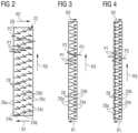
- the movement paths of the powdery material M relative to the surface profile 22 during a movement of the powder carrier 16 over the carrier plane E in a first movement direction R1 are shown in the Figures 2 to 4 illustrated by the arrows P1.
- the arrows P2 in the Figures 2 to 4 the movement paths of the powdery material M relative to the surface profile 22 during a movement of the powder driver 16 over the carrier plane E in a second movement direction R2.
- Powdery material M that accumulates on the support plane E in front of the gas outlet 110 can be removed from this area of the support plane E with the help of the powder carrier 16 and pushed over the support plane E by the powder carrier 16 in the first direction of movement R1 of the powder carrier 16.
- the powder carrier 16 is prevented from transporting powdery material M deposited on the support plane E into the area of the support plane E in front of the gas outlet 110 when moving over the support plane E in the second direction of movement R2. This can prevent an undesirable accumulation of powdery material M in the vicinity of the gas outlet 110.
- the driving elements 24a, 24b, 24c formed on the powder driver 16 are tapered in the region of a front end relative to the movement of the powder driver 16 over the carrier plane E in the second direction of movement R2.
- the powdery material M can be guided past the driving elements 24a, 24b, 24c into the passage channels 26a, 26b, 26c present between the driving elements 24a, 24b, 24c when the powder driver 16 moves over the carrier plane E in the second direction of movement R2.
- the driving elements 24a, 24b, 24c are provided with a powder collecting section 28 in the region of a front end relative to the movement of the powder driver 16 over the carrier plane E in the first direction of movement R1.
- the powder collecting section 28 is formed by a cavity delimited by side walls of the driving elements 24a, 24b, 24c.
- the Figure 4 The carrier elements 24a, 24b, 24c shown each have a powder collecting section 28 which is formed by a curved surface which, when the powder carrier 16 moves over the carrier plane E in the first direction of movement R1, comes into contact with the powdery material M deposited on the carrier plane E and accordingly carries it along.
- the driving elements 24a, 24b, 24c of the surface profile 22 according to Figure 2 are hook-shaped, while the driving elements 24a, 24b, 24c of the surface profile 22 according to Figure 3 V-shaped.
- the driving elements 24a, 24b, 24c of the surface profile 2 20 according to Figure 4 are, however, wedge-shaped and, as described above, are provided with a powder collecting section 28 defined by a curved surface.
- the driving elements 24a, 24b, 24c are divided into several groups in all three surface profile variants shown here.
- each of the Figures 2 to 4 shown surface profiles 22 a first group of driving elements 24a, which are arranged next to one another in a row in a direction R3 that is substantially perpendicular to the first and second movement directions R1, R2 of the powder driver 16 over the carrier plane E.
- the direction R3 that is perpendicular to the first and second movement directions R1, R2 extends parallel to a longitudinal axis L of the powder driver 16.
- a passage channel 26a Between each adjacent driving element 24a of the first group there is a passage channel 26a.
- each of the surface profiles 22 comprises a second group of carrier elements 24b, which are arranged next to one another in a row in the direction R3, which is substantially perpendicular to the first and second movement directions R1, R2.
- the carrier elements 24b of the second group are arranged at least partially in the passage channels 26a present between the carrier elements 24a of the first group, relative to the first movement direction R1 of the powder carrier 16, over the carrier plane E behind the first group of carrier elements 24a.
- the driving elements 24b of the second group are shaped and arranged so that they a movement of the powder carrier 16 over the carrier plane E in the first direction of movement R1 between the carrier elements 24a of the first group, collect and carry powdery material M entering the passage channels 26a, see arrows P1 in the Figures 2 to 4 .
- the carrier elements 24a of the first group initially strike the powdery material M deposited on the support plane E. Part of the powdery material M is then caught and carried along by the carrier elements 24a of the first group, i.e. in particular their powder collecting sections 28.
- Powdery material M which initially enters the passage channels 26a between the carrier elements 24a of the first group, on the other hand, strikes the carrier elements 24b of the second group as the powder carrier 16 continues to move over the support plane E in the first direction of movement R1 and is caught and carried along by these, i.e. in particular their powder collecting sections 28.
- the driving elements 24b of the second group are shaped and arranged in such a way that, when the powder driver 16 moves over the carrier plane E in the second direction of movement R2, they guide powdery material M entering the passage channels 26a through the passage channels 26a, ie they allow the powdery material M to pass through the passage channels 26a, see arrows P2 in the Figures 2 to 4 .
- the carrier elements 24a of the first group are arranged behind the carrier elements 24b of the second group with respect to the second direction of movement R2 of the powder carrier 16 over the carrier plane E. Consequently, when the powder carrier 16 moves over the carrier plane E in the second direction of movement R2, first the carrier elements 24b of the second group and only then the carrier elements 24a of the first group hit the material M deposited on the carrier plane E. In contrast, the carrier elements 24a of the first group are arranged behind the carrier elements 24b of the second group with respect to the second direction of movement R2 of the powder carrier 16 over the carrier plane E.
- Figures 3 and 4 shown surface profiles 22 are designed such that the driving elements 24b of the second group are arranged at the same height as the driving elements 24a of the first group with respect to the second direction of movement R2 of the powder driver 16 over the carrier plane E.
- the driving elements 24a, 24b of the first and second groups simultaneously hit the powdery material deposited on the carrier plane E. Material M, so that the powdery material is guided past the driving elements 24b of the second group through the passage channels 26a provided between the driving elements 24a of the first group.
- the driving elements 24b of the second group are further arranged offset from the driving elements 24a of the first group in the direction R3 which is substantially perpendicular to the first and second movement directions R1, R2 of the powder driver 16 over the carrier plane E, wherein a driving element 24b of the second group protrudes into each passage channel 26a present between two driving elements 24a of the first group.
- the Figure 2 shown surface profile 22 a third group of driving elements 24c.
- the driving elements 24c of the third group are arranged in a row next to one another in the direction R3, which is substantially perpendicular to the first and second movement directions R1, R2 of the powder driver 16 over the carrier plane E, and offset from the driving elements 24a, 24b of the first and second group.
- the carrier elements 24c of the third group are arranged behind the second group 24b of carrier elements and each protrude into passage channels 26b present between the carrier elements 24b of the second group.
- the surface profile 22 comprises Figure 2 Passage channels 26c, which are each arranged between two adjacent carrier elements 24c of the third group.
- Each passage channel 26a is connected to a passage channel 26b and each passage channel 26b is in turn connected to a passage channel 26c, so that material M deposited on the carrier plane E can pass through the passage channels 26c, 26b, 26a one after the other when the powder carrier 16 moves over the carrier plane E in the second movement direction R2, see arrows P2 in Figure 2 .
- the driving elements 24a of the first group, the driving elements 24b of the second group and the driving elements 24c of the third group are identically shaped.
- the driving elements 24a of the first group and the driving elements 24b of the second group in the surface profiles 22 according to the Figures 3 and 4 only an identical geometric basic shape, but are different sizes.
- the driving elements 24b of the second group are smaller than the driving elements 24b of the first group.
- the powder material M carried by the powder carrier 16 during a movement over the carrier plane E in the first direction of movement R1 is conveyed by the powder carrier 16 into a collecting shaft 120 which, with respect to the movement of the powder carrier 16 over the carrier plane E in the first direction of movement R1, is arranged behind the carrier 116 and offset from the carrier 116 in the direction R3 which is substantially perpendicular to the first and second directions of movement R1, R2 of the powder carrier 16 over the carrier plane E. Accordingly, the collecting shaft 120 is sufficiently far away from the gas outlet 110 of the process chamber 102.
- the collecting shaft 120 is arranged adjacent to a first overflow shaft 122.
- the first overflow shaft 122 serves to receive excess raw material powder that is transported away from the surface of the carrier 116 by the distribution element 12 during a movement over the surface of the carrier 116 in the first movement direction R1.
- a second overflow shaft 124 is provided, which serves to receive excess raw material powder that is transported away from the surface of the carrier 116 by the distribution element 12 during a movement over the surface of the carrier 116 in the second movement direction R2.
- the collecting shaft 120 and the first overflow shaft 122 are covered by a common shaft grid 126.
- the collecting shaft 120 is, however, separated from the first overflow shaft 122 by a partition wall 128.
- the powdery material M conveyed by the powder carrier 16 into the collecting shaft 120 can be separated from the excess raw material powder conveyed by the distribution element 12 into the first overflow shaft 122 and discharged separately from the process chamber 102.
- the uncontaminated excess raw material powder from the first overflow shaft 122 can then be reused immediately.
- the powdery material M from the collecting shaft 120 can either be disposed of or processed for further use.
Landscapes
- Engineering & Computer Science (AREA)
- Chemical & Material Sciences (AREA)
- Manufacturing & Machinery (AREA)
- Materials Engineering (AREA)
- Mechanical Engineering (AREA)
- Life Sciences & Earth Sciences (AREA)
- Sustainable Development (AREA)
- Ceramic Engineering (AREA)
- Physics & Mathematics (AREA)
- Optics & Photonics (AREA)
- Powder Metallurgy (AREA)
- Producing Shaped Articles From Materials (AREA)
Claims (15)
- Dispositif d'application de poudre (10) destiné à être utilisé dans une installation (100) pour la fabrication d'une pièce tridimensionnelle selon un procédé de fabrication additive, le dispositif d'application de poudre (10) comprenant:- un élément de distribution (12) mobile sur une surface d'un support (116) pour appliquer une poudre de matière première sur la surface du support (116) pour fabriquer une pièce selon un procédé de fabrication additive, et- un entraîneur de poudre (16) mobile sur un plan de support (E), qui est pourvu, dans la zone d'une surface (20) tournée vers le plan de support (E), d'un profil de surface (22) qui comprend un élément d'entraînement (24a, 24b, 24c) ainsi qu'un canal de passage (26a, 26b, 26c), l'élément d'entraînement (24a, 24b, 24c) et le canal de passage (26a, 26b, 26c) étant formés et disposés de manière à ce que, par rapport au mouvement de l'entraîneur de poudre (16) sur le plan de support (E), la matière pulvérulente déposée sur le plan de support (E) devant l'entraîneur de poudre (16) est entraînée par l'élément d'entraînement (24a, 24b, 24c, 24d) dans une première direction de déplacement (R1) et lors d'un déplacement de l'entraîneur de poudre (16) sur le plan de support (E), et, lors d'un déplacement de l'entraîneur de poudre (16) sur le plan de support (E), dans une deuxième direction de déplacement (R2) opposée à la première direction de déplacement (R1), est guidé à travers le canal de passage (26a, 26b, 26c).
- Dispositif d'application de poudre selon la revendication 1,
dans lequel l'entraîneur de poudre (16) est fixé à l'élément de distribution (12) et s'étend en particulier dans une direction (R3) sensiblement perpendiculaire à la première et à la deuxième direction de déplacement (R1, R2) de l'entraîneur de poudre (16) sur le plan de support (E) à partir d'une surface latérale de l'élément de distribution (12). - Dispositif d'application de poudre selon la revendication 1 ou 2,
dans lequel le profil de surface (22) comprend une pluralité d'éléments d'entraînement (24a, 24b, 24c) et une pluralité de canaux de passage (26a, 26b, 26c) disposés entre les éléments d'entraînement (24a, 24b, 24c), et dans lequel- au moins une partie des éléments d'entraînement (24a, 24b, 24c) est réalisée en se terminant en pointe dans la zone d'une extrémité avant par rapport au déplacement de l'entraîneur de poudre (16) sur le plan de support (E) dans la deuxième direction de déplacement (R2), et/ou- au moins une partie des éléments d'entraînement (24a, 24b, 24c) est pourvue d'une section de collecte de poudre (28) dans la zone d'une extrémité avant par rapport au déplacement de l'entraîneur de poudre (16) sur le plan de support (E) dans la première direction de déplacement (R1). - Dispositif d'application de poudre selon l'une quelconque des revendications 1 à 3,
dans lequel le profil de surface (22) comprend une pluralité d'éléments d'entraînement (24a, 24b, 24c) ainsi qu'une pluralité de canaux de passage (26a, 26b, 26c) disposés entre les éléments d'entraînement (24a, 24b, 24c) et au moins une partie des éléments d'entraînement (24a, 24b, 24c) étant réalisée en forme de V, de coin et/ou de crochet. - Dispositif d'application de poudre selon l'une quelconque des revendications 1 à 4,
dans lequel le profil de surface (22) de l'entraîneur de poudre (16) comprenant un premier groupe d'éléments d'entraînement (24a) qui sont disposés en une rangée les uns à côté des autres dans la direction (R3) essentiellement perpendiculaire à la première et à la deuxième direction de déplacement (R1, R2) de l'entraîneur de poudre (16) sur le plan de support (E), un canal de passage (26a) étant respectivement présent entre des éléments d'entraînement (24a) voisins les uns aux autres du premier groupe. - Dispositif d'application de poudre selon la revendication 5,
dans lequel le profil de surface (22) de l'entraîneur de poudre (16) comprend un deuxième groupe d'éléments d'entraînement (24b) qui sont disposés en une rangée les uns à côté des autres dans la direction perpendiculaire (R3) par rapport à la première et à la deuxième direction de déplacement (R1, R2) de l'entraîneur de poudre (16) sur le plan de support (E) et, par rapport à la première direction de déplacement (R1) de l'entraîneur de poudre (16) sur le plan de support (E), derrière le premier groupe d'éléments d'entraînement (24a) au moins partiellement dans les canaux de passage (26a) présents entre les éléments d'entraînement (24a) du premier groupe. - Dispositif d'application de poudre selon la revendication 6,
dans lequel les éléments d'entraînement (24b) du deuxième groupe étant formés et disposés de manière à ce que, lors d'un déplacement de l'entraîneur de poudre (16) sur le plan de support (E) dans la première direction de déplacement (R1), ils interceptent et entraînent dans les canaux de passage (26a) la matière pulvérulente qui pénètre entre les éléments d'entraînement (24a) du premier groupe. - Dispositif d'application de poudre selon la revendication 6 ou 7,
dans lequel les éléments d'entraînement (24b) du deuxième groupe sont formés et disposés de manière à ce que, lors d'un déplacement de l'entraîneur de poudre (16) sur le plan de support (E) dans la deuxième direction de déplacement (R2), ils guident la matière pulvérulente par les canaux de passage (26a) entrant dans les canaux de passage (26a). - Dispositif d'application de poudre selon l'une quelconque des revendications 6 à 8,
dans lequel- les éléments d'entraînement (24b) du deuxième groupe sont décalés par rapport aux éléments d'entraînement (24a) du premier groupe dans la direction (R3) essentiellement perpendiculaire à la première et à la deuxième direction de déplacement (R1, R2) de l'entraîneur de poudre (16) sur le plan de support (E),- le profil de surface (22) de l'entraîneur de poudre (16) comprend un troisième groupe d'éléments d'entraînement (24c) qui, dans la direction (R3) essentiellement perpendiculaire à la première et à la deuxième direction de déplacement (R1, R2) de l'entraîneur de poudre (16) sur le plan de support (E), sont disposés en une rangée les uns à côté des autres et/ou décalés par rapport aux éléments d'entraînement (24a, 24b) du premier et/ou du deuxième groupe, et/ou qui, par rapport à la première direction de déplacement (R1) de l'entraîneur de poudre (16) sur le plan porteur (E), sont disposés derrière le deuxième groupe d'éléments d'entraînement (24b) au moins partiellement dans des canaux de passage (26bc) présents entre les éléments d'entraînement (24b) du deuxième groupe, et/ou- les éléments d'entraînement (24a) du premier groupe, les éléments d'entraînement (24b) du deuxième groupe et/ou les éléments d'entraînement (24c) du troisième groupe sont formés de manière sensiblement identique. - Dispositif d'application de poudre selon l'une quelconque des revendications 6 à 8,
dans lequel- les éléments d'entraînement (24b) du deuxième groupe sont entièrement disposés dans les canaux de passage (26a) présents entre les éléments d'entraînement (24a) du premier groupe et/ou- les éléments d'entraînement (24a) du premier groupe et les éléments d'entraînement (24b) du deuxième groupe présentent une forme géométrique de base sensiblement identique et/ou les éléments d'entraînement (24b) du deuxième groupe sont plus petits que les éléments d'entraînement (24a) du premier groupe. - Procédé de fonctionnement d'un dispositif d'application de poudre (10), qui est adapté pour à être utilisé dans une installation (100) pour la fabrication d'une pièce tridimensionnelle selon un procédé de fabrication additive, le procédé comprend les étapes suivantes consistant:- déplacer un élément de distribution (12) sur une surface d'un support (116) afin de déposer une poudre de matière première sur la surface du support (116) pour fabriquer une pièce selon un procédé de fabrication additive, et- déplacer un entraîneur de poudre (16) sur un plan de support (E), l'entraîneur de poudre (16) étant pourvu, dans la zone d'une surface (20) tournée vers le plan de support (E), d'un profil de surface (22) qui comprend un élément d'entraînement (24a, 24b, 24c) ainsi qu'un canal de passage (26a, 26b, 26c), l'élément d'entraînement (24a, 24b, 24c) et le canal de passage (26a, 26b, 26c) étant formés et disposés de manière à ce que, par rapport au déplacement de l'entraîneur de poudre (16) sur le plan de support (E), la matière pulvérulente déposée sur le plan de support (E) devant l'entraîneur de poudre (16) soit entraînée par l'élément d'entraînement (24a, 24b, 24c) dans une première direction de déplacement (R1) et lors d'un déplacement de l'entraîneur de poudre (16) sur le plan de support (E), dans une deuxième direction de déplacement (R2) opposée à la première direction de déplacement (R1), soit guidé dans le canal de passage (26a, 26b, 26c).
- Procédé selon la revendication 11,
dans lequel la matière pulvérulente déposée sur le plan de support (E) devant l'entraîneur de poudre (16), par rapport au déplacement de l'entraîneur de poudre (16) sur le plan de support (E), est transportée, lors d'un déplacement de l'entraîneur de poudre (16) sur la surface du support (116) dans la première direction de déplacement (R1), dans un puits de collecte (120) et/ou une zone de collecte située en dehors d'une zone critique d'écoulement de gaz. - Installation (100) pour la fabrication d'une pièce tridimensionnelle selon un procédé de fabrication additive, qui comprend un dispositif d'application de poudre (10) selon l'une quelconque des revendications 1 à 10.
- Installation selon la revendication 13,
qui comprend en outre un puits de collecte (120) et/ou une zone de collecte située en dehors d'une zone critique d'écoulement de gaz qui est conçu pour recevoir la matière pulvérulente en provenance de l'entraîneur de poudre (16) lors de son déplacement dans le plan de support (E) dans une première direction de déplacement (R1). - Installation selon la revendication 14,
dans laquelle le puits de collecte (120)- est disposé derrière le support (116) dans la première direction de déplacement (R1) par rapport au déplacement de l'entraîneur de poudre (16) sur le plan de support (E ) et/ou- est décalé par rapport au support (116) dans la direction (R3) sensiblement perpendiculaire à la première et à la deuxième direction de déplacement (R1, R2) de l'entraîneur de poudre (16) sur le plan de support (E).
Applications Claiming Priority (2)
| Application Number | Priority Date | Filing Date | Title |
|---|---|---|---|
| DE102018128242.7A DE102018128242B4 (de) | 2018-11-12 | 2018-11-12 | Pulverauftragsvorrichtung, Verfahren zum Betreiben einer Pulverauftragsvorrichtung und Anlage zur Herstellung eines dreidimensionalen Werkstücks |
| PCT/EP2019/080384 WO2020099211A1 (fr) | 2018-11-12 | 2019-11-06 | Dispositif d'application de poudre, procédé de fonctionnement d'un dispositif d'application de poudre et installation de fabrication d'une pièce tridimensionnelle |
Publications (2)
| Publication Number | Publication Date |
|---|---|
| EP3880389A1 EP3880389A1 (fr) | 2021-09-22 |
| EP3880389B1 true EP3880389B1 (fr) | 2024-08-28 |
Family
ID=68470528
Family Applications (1)
| Application Number | Title | Priority Date | Filing Date |
|---|---|---|---|
| EP19798631.8A Active EP3880389B1 (fr) | 2018-11-12 | 2019-11-06 | Dispositif d'application de poudre, procédé de fonctionnement d'un dispositif d'application de poudre et installation de fabrication d'une pièce tridimensionnelle |
Country Status (6)
| Country | Link |
|---|---|
| US (1) | US12290859B2 (fr) |
| EP (1) | EP3880389B1 (fr) |
| JP (1) | JP7110487B2 (fr) |
| CN (1) | CN113165078B (fr) |
| DE (1) | DE102018128242B4 (fr) |
| WO (1) | WO2020099211A1 (fr) |
Families Citing this family (2)
| Publication number | Priority date | Publication date | Assignee | Title |
|---|---|---|---|---|
| CN116018271A (zh) * | 2020-09-04 | 2023-04-25 | 伏尔肯模型公司 | 用于增材制造用的重涂系统的缺陷减轻 |
| DE102021107265A1 (de) * | 2021-03-23 | 2022-09-29 | Eos Gmbh Electro Optical Systems | Vorrichtung zur additiven Fertigung von Fertigungsprodukten |
Family Cites Families (25)
| Publication number | Priority date | Publication date | Assignee | Title |
|---|---|---|---|---|
| US20050263934A1 (en) * | 2004-05-28 | 2005-12-01 | 3D Systems, Inc. | Single side feed parked powder wave heating with wave flattener |
| DE102012200161A1 (de) * | 2012-01-06 | 2013-07-11 | Evonik Industries Ag | Vorrichtung zur schichtweisen Herstellung von dreidimensionalen Objekten |
| JP6200969B2 (ja) | 2013-02-27 | 2017-09-20 | エスエルエム ソルーションズ グループ アーゲー | 調整された微細構造を備えるワークピースの製造装置及び製造方法 |
| EP2818305B1 (fr) | 2013-06-25 | 2016-03-23 | SLM Solutions GmbH | Appareil d'application de poudre et procédé de fonctionnement d'un appareil d'application de poudre |
| EP2862651B1 (fr) * | 2013-10-15 | 2019-07-17 | SLM Solutions Group AG | Procédé et appareil de fabrication additive de pièces tridimensionnelles de grande taille |
| WO2015119692A2 (fr) * | 2013-11-14 | 2015-08-13 | General Electric Company | Fabrication en couches de composants en alliage monocristallin |
| EP2878402A1 (fr) | 2013-12-02 | 2015-06-03 | SLM Solutions Group AG | Appareil et procédé de fabrication de pièces tridimensionnelle avec un dispositif de détection de rayonnement |
| CN106660123B (zh) * | 2014-08-20 | 2019-11-05 | 艾西塔股份公司 | 使用光束的增材制造方法和系统 |
| CN105562687B (zh) * | 2014-10-10 | 2018-12-25 | 南京理工大学 | 不同粉末复合使用的选区激光熔融送粉铺粉装置 |
| DE102015109848A1 (de) | 2015-06-19 | 2016-12-22 | Aconity3D Gmbh | PBLS-Anlage |
| DE102015213103A1 (de) | 2015-07-13 | 2017-01-19 | Eos Gmbh Electro Optical Systems | Verfahren und Vorrichtung zum Herstellen eines dreidimensionalen Objekts |
| US10814387B2 (en) | 2015-08-03 | 2020-10-27 | General Electric Company | Powder recirculating additive manufacturing apparatus and method |
| US10583483B2 (en) | 2015-10-15 | 2020-03-10 | Arcam Ab | Method and apparatus for producing a three-dimensional article |
| EP3159081B1 (fr) | 2015-10-21 | 2023-12-06 | Nikon SLM Solutions AG | Dispositif d'application de poudre comprenant deux caméras |
| FR3046095B1 (fr) | 2015-12-23 | 2018-01-26 | Addup | Machine de fabrication additive et procede de fabrication additive mettant en oeuvre une telle machine |
| FR3046094A1 (fr) | 2015-12-23 | 2017-06-30 | Michelin & Cie | Procede de fabrication additive d'une piece par fusion selective totale ou partielle d'une poudre et machine adaptee a la mise en oeuvre d'un tel procede |
| CN107303608B (zh) | 2016-04-23 | 2021-05-25 | 罗天珍 | 3d打印用微梳铺粉法及带有梳状刮粉片的打印机 |
| CN107433714B (zh) * | 2016-05-25 | 2024-03-19 | 罗天珍 | 粉末3d打印专用融合微梳铺粉法及铺粉装置 |
| DE102016211799A1 (de) * | 2016-06-30 | 2018-01-04 | Robert Bosch Gmbh | Vorrichtung zum generativen Herstellen von Werkstücken |
| EP3281727B8 (fr) | 2016-08-10 | 2023-11-22 | Nikon SLM Solutions AG | Appareil de production de pièces tridimensionnelles comprenant une pluralité de dispositifs d'application de poudre |
| WO2018090188A1 (fr) | 2016-11-15 | 2018-05-24 | 东台精机股份有限公司 | Épandeur de poudre à récupération automatique de poudre |
| EP3391981A1 (fr) * | 2017-04-18 | 2018-10-24 | Heraeus Additive Manufacturing GmbH | Revêtement continu de bandes métalliques par fabrication additive |
| CN108544753B (zh) * | 2018-05-07 | 2024-04-05 | 湖南华曙高科技股份有限公司 | 双向铺粉装置、供粉铺粉装置及增材制造设备 |
| CN108480639B (zh) * | 2018-05-30 | 2023-11-21 | 吉林大学 | 一种电子束钛合金粉末熔融成形的铺粉装置 |
| US11338519B2 (en) * | 2019-07-26 | 2022-05-24 | Arcam Ab | Devices, systems, and methods for monitoring a powder layer in additive manufacturing processes |
-
2018
- 2018-11-12 DE DE102018128242.7A patent/DE102018128242B4/de active Active
-
2019
- 2019-11-06 EP EP19798631.8A patent/EP3880389B1/fr active Active
- 2019-11-06 US US17/292,614 patent/US12290859B2/en active Active
- 2019-11-06 WO PCT/EP2019/080384 patent/WO2020099211A1/fr not_active Ceased
- 2019-11-06 CN CN201980081109.3A patent/CN113165078B/zh active Active
- 2019-11-06 JP JP2021525622A patent/JP7110487B2/ja active Active
Also Published As
| Publication number | Publication date |
|---|---|
| JP7110487B2 (ja) | 2022-08-01 |
| CN113165078A (zh) | 2021-07-23 |
| DE102018128242B4 (de) | 2025-02-20 |
| JP2022507174A (ja) | 2022-01-18 |
| DE102018128242A1 (de) | 2020-05-14 |
| WO2020099211A1 (fr) | 2020-05-22 |
| EP3880389A1 (fr) | 2021-09-22 |
| CN113165078B (zh) | 2023-02-28 |
| US12290859B2 (en) | 2025-05-06 |
| US20220009000A1 (en) | 2022-01-13 |
Similar Documents
| Publication | Publication Date | Title |
|---|---|---|
| EP1137504B1 (fr) | Chambre de processus pour la fusion selective par laser | |
| DE19935274C1 (de) | Vorrichtung und Verfahren zur Herstellung von Bauteilen aus einer Werkstoffkombination | |
| EP3174691B1 (fr) | Procédé, dispositif et unité de commande pour fabriquer un objet tridimensionnel | |
| EP2340925B1 (fr) | Procédé de fabrication générative d'un objet tridimensionnel doté d'une amenée de chaleur en continu | |
| DE102015116923B4 (de) | 3D-Drucker | |
| EP4116018B1 (fr) | Dispositif et procédé de fabrication de pièces tridimensionnelles | |
| DE102014209161A1 (de) | Steuereinheit, Vorrichtung und Verfahren zum Herstellen eines dreidimensionalen Objekts | |
| DE102014205875A1 (de) | Vorrichtung und Verfahren zum schichtweisen Herstellen eines dreidimensionalen Objekts | |
| WO2018054727A1 (fr) | Procédé de fabrication d'une pièce au moyen d'un procédé de fabrication additive et dispositif adapté à la mise en œuvre du procédé | |
| DE102018210260A1 (de) | Vorrichtung und Verfahren zum generativen Herstellen eines dreidimensionalen Objekts | |
| DE102017222645A1 (de) | Einrichtung zur Schutzgaszufuhr und Erwärmung und/oder Pulverzufuhr sowie Vorrichtung und Verfahren zur additiven Herstellung von Bauteilen und Bauteil | |
| EP3880389B1 (fr) | Dispositif d'application de poudre, procédé de fonctionnement d'un dispositif d'application de poudre et installation de fabrication d'une pièce tridimensionnelle | |
| EP3328619A1 (fr) | Procédé et dispositif de fabrication d'un objet tridimensionnel | |
| DE102017207256A1 (de) | Erhöhung der Oberflächenqualität | |
| DE102013221014A1 (de) | Beseitigungsvorrichtung und Verfahren zum Beseitigen zumindest von Schweißablagerungen in einer Anlage zum Herstellen eines Bauteils mittels Auftragung von Pulverschichten | |
| DE102011106380B4 (de) | Vorrichtung zur Herstellung von dreidimensionalen Objekten | |
| DE102016222947A1 (de) | Vorrichtung und Verfahren zur additiven Herstellung eines dreidimensionalen Produktes | |
| DE102023110357A1 (de) | Vorrichtung und Verfahren zur gerichteten Gasbeaufschlagung eines Bauraums zur additiven Fertigung | |
| WO2019166374A1 (fr) | Dispositif de fabrication d'un corps moulé | |
| DE102019113841A1 (de) | Verfahren zur additiven Fertigung dreidimensionaler Bauteile sowie entsprechende Vorrichtung | |
| EP3986645B1 (fr) | Procédé et dispositif de fabrication d'une pièce multi-matériaux | |
| DE102022201999A1 (de) | Strömungsmodifikationselement, Beströmungsvorrichtung und Beströmungsverfahren für eine additive Herstellvorrichtung | |
| DE102019214802A1 (de) | Beschichtervorrichtung für die Verwendung in einem additiven Fertigungsverfahren, Fertigungsanlage für die Verwendung in einem additiven Fertigungsverfahren sowie ein Gehäuse für eine Beschichtervorrichtung für die Verwendung in einem additiven Fertigungsverfahren | |
| DE102023108180A1 (de) | Vorrichtung zur additiven Herstellung eines Formkörpers durch sukzessive schichtweise selektive Bestrahlung | |
| DE102024200430A1 (de) | Schutzvorrichtung für einen Belichter einer additiven Herstellvorrichtung |
Legal Events
| Date | Code | Title | Description |
|---|---|---|---|
| STAA | Information on the status of an ep patent application or granted ep patent |
Free format text: STATUS: UNKNOWN |
|
| STAA | Information on the status of an ep patent application or granted ep patent |
Free format text: STATUS: THE INTERNATIONAL PUBLICATION HAS BEEN MADE |
|
| PUAI | Public reference made under article 153(3) epc to a published international application that has entered the european phase |
Free format text: ORIGINAL CODE: 0009012 |
|
| STAA | Information on the status of an ep patent application or granted ep patent |
Free format text: STATUS: REQUEST FOR EXAMINATION WAS MADE |
|
| 17P | Request for examination filed |
Effective date: 20210504 |
|
| AK | Designated contracting states |
Kind code of ref document: A1 Designated state(s): AL AT BE BG CH CY CZ DE DK EE ES FI FR GB GR HR HU IE IS IT LI LT LU LV MC MK MT NL NO PL PT RO RS SE SI SK SM TR |
|
| DAV | Request for validation of the european patent (deleted) | ||
| DAX | Request for extension of the european patent (deleted) | ||
| RAP1 | Party data changed (applicant data changed or rights of an application transferred) |
Owner name: NIKON SLM SOLUTIONS AG |
|
| RIN1 | Information on inventor provided before grant (corrected) |
Inventor name: FRANK, RALF Inventor name: KOERNER, PETER |
|
| REG | Reference to a national code |
Ref country code: DE Ref legal event code: R079 Free format text: PREVIOUS MAIN CLASS: B22F0003105000 Ipc: B22F0010730000 Ref country code: DE Ref legal event code: R079 Ref document number: 502019012010 Country of ref document: DE Free format text: PREVIOUS MAIN CLASS: B22F0003105000 Ipc: B22F0010730000 |
|
| GRAP | Despatch of communication of intention to grant a patent |
Free format text: ORIGINAL CODE: EPIDOSNIGR1 |
|
| STAA | Information on the status of an ep patent application or granted ep patent |
Free format text: STATUS: GRANT OF PATENT IS INTENDED |
|
| INTG | Intention to grant announced |
Effective date: 20240328 |
|
| RIC1 | Information provided on ipc code assigned before grant |
Ipc: B22F 12/70 20210101ALN20240315BHEP Ipc: B22F 10/77 20210101ALN20240315BHEP Ipc: B22F 10/32 20210101ALN20240315BHEP Ipc: B22F 10/28 20210101ALN20240315BHEP Ipc: B29C 64/214 20170101ALI20240315BHEP Ipc: B33Y 40/00 20200101ALI20240315BHEP Ipc: B33Y 30/00 20150101ALI20240315BHEP Ipc: B33Y 10/00 20150101ALI20240315BHEP Ipc: B22F 12/67 20210101ALI20240315BHEP Ipc: B22F 12/50 20210101ALI20240315BHEP Ipc: B22F 10/73 20210101AFI20240315BHEP |
|
| GRAS | Grant fee paid |
Free format text: ORIGINAL CODE: EPIDOSNIGR3 |
|
| GRAA | (expected) grant |
Free format text: ORIGINAL CODE: 0009210 |
|
| STAA | Information on the status of an ep patent application or granted ep patent |
Free format text: STATUS: THE PATENT HAS BEEN GRANTED |
|
| AK | Designated contracting states |
Kind code of ref document: B1 Designated state(s): AL AT BE BG CH CY CZ DE DK EE ES FI FR GB GR HR HU IE IS IT LI LT LU LV MC MK MT NL NO PL PT RO RS SE SI SK SM TR |
|
| REG | Reference to a national code |
Ref country code: GB Ref legal event code: FG4D Free format text: NOT ENGLISH |
|
| REG | Reference to a national code |
Ref country code: CH Ref legal event code: EP |
|
| REG | Reference to a national code |
Ref country code: DE Ref legal event code: R096 Ref document number: 502019012010 Country of ref document: DE |
|
| REG | Reference to a national code |
Ref country code: IE Ref legal event code: FG4D Free format text: LANGUAGE OF EP DOCUMENT: GERMAN |
|
| REG | Reference to a national code |
Ref country code: NL Ref legal event code: FP |
|
| REG | Reference to a national code |
Ref country code: LT Ref legal event code: MG9D |
|
| PG25 | Lapsed in a contracting state [announced via postgrant information from national office to epo] |
Ref country code: NO Free format text: LAPSE BECAUSE OF FAILURE TO SUBMIT A TRANSLATION OF THE DESCRIPTION OR TO PAY THE FEE WITHIN THE PRESCRIBED TIME-LIMIT Effective date: 20241128 |
|
| PG25 | Lapsed in a contracting state [announced via postgrant information from national office to epo] |
Ref country code: FI Free format text: LAPSE BECAUSE OF FAILURE TO SUBMIT A TRANSLATION OF THE DESCRIPTION OR TO PAY THE FEE WITHIN THE PRESCRIBED TIME-LIMIT Effective date: 20240828 Ref country code: GR Free format text: LAPSE BECAUSE OF FAILURE TO SUBMIT A TRANSLATION OF THE DESCRIPTION OR TO PAY THE FEE WITHIN THE PRESCRIBED TIME-LIMIT Effective date: 20241129 Ref country code: PT Free format text: LAPSE BECAUSE OF FAILURE TO SUBMIT A TRANSLATION OF THE DESCRIPTION OR TO PAY THE FEE WITHIN THE PRESCRIBED TIME-LIMIT Effective date: 20241230 Ref country code: PL Free format text: LAPSE BECAUSE OF FAILURE TO SUBMIT A TRANSLATION OF THE DESCRIPTION OR TO PAY THE FEE WITHIN THE PRESCRIBED TIME-LIMIT Effective date: 20240828 |
|
| PG25 | Lapsed in a contracting state [announced via postgrant information from national office to epo] |
Ref country code: BG Free format text: LAPSE BECAUSE OF FAILURE TO SUBMIT A TRANSLATION OF THE DESCRIPTION OR TO PAY THE FEE WITHIN THE PRESCRIBED TIME-LIMIT Effective date: 20240828 |
|
| PG25 | Lapsed in a contracting state [announced via postgrant information from national office to epo] |
Ref country code: LV Free format text: LAPSE BECAUSE OF FAILURE TO SUBMIT A TRANSLATION OF THE DESCRIPTION OR TO PAY THE FEE WITHIN THE PRESCRIBED TIME-LIMIT Effective date: 20240828 |
|
| PG25 | Lapsed in a contracting state [announced via postgrant information from national office to epo] |
Ref country code: IS Free format text: LAPSE BECAUSE OF FAILURE TO SUBMIT A TRANSLATION OF THE DESCRIPTION OR TO PAY THE FEE WITHIN THE PRESCRIBED TIME-LIMIT Effective date: 20241228 |
|
| PG25 | Lapsed in a contracting state [announced via postgrant information from national office to epo] |
Ref country code: HR Free format text: LAPSE BECAUSE OF FAILURE TO SUBMIT A TRANSLATION OF THE DESCRIPTION OR TO PAY THE FEE WITHIN THE PRESCRIBED TIME-LIMIT Effective date: 20240828 |
|
| PG25 | Lapsed in a contracting state [announced via postgrant information from national office to epo] |
Ref country code: RS Free format text: LAPSE BECAUSE OF FAILURE TO SUBMIT A TRANSLATION OF THE DESCRIPTION OR TO PAY THE FEE WITHIN THE PRESCRIBED TIME-LIMIT Effective date: 20241128 Ref country code: ES Free format text: LAPSE BECAUSE OF FAILURE TO SUBMIT A TRANSLATION OF THE DESCRIPTION OR TO PAY THE FEE WITHIN THE PRESCRIBED TIME-LIMIT Effective date: 20240828 |
|
| PG25 | Lapsed in a contracting state [announced via postgrant information from national office to epo] |
Ref country code: RS Free format text: LAPSE BECAUSE OF FAILURE TO SUBMIT A TRANSLATION OF THE DESCRIPTION OR TO PAY THE FEE WITHIN THE PRESCRIBED TIME-LIMIT Effective date: 20241128 Ref country code: PT Free format text: LAPSE BECAUSE OF FAILURE TO SUBMIT A TRANSLATION OF THE DESCRIPTION OR TO PAY THE FEE WITHIN THE PRESCRIBED TIME-LIMIT Effective date: 20241230 Ref country code: PL Free format text: LAPSE BECAUSE OF FAILURE TO SUBMIT A TRANSLATION OF THE DESCRIPTION OR TO PAY THE FEE WITHIN THE PRESCRIBED TIME-LIMIT Effective date: 20240828 Ref country code: NO Free format text: LAPSE BECAUSE OF FAILURE TO SUBMIT A TRANSLATION OF THE DESCRIPTION OR TO PAY THE FEE WITHIN THE PRESCRIBED TIME-LIMIT Effective date: 20241128 Ref country code: LV Free format text: LAPSE BECAUSE OF FAILURE TO SUBMIT A TRANSLATION OF THE DESCRIPTION OR TO PAY THE FEE WITHIN THE PRESCRIBED TIME-LIMIT Effective date: 20240828 Ref country code: IS Free format text: LAPSE BECAUSE OF FAILURE TO SUBMIT A TRANSLATION OF THE DESCRIPTION OR TO PAY THE FEE WITHIN THE PRESCRIBED TIME-LIMIT Effective date: 20241228 Ref country code: HR Free format text: LAPSE BECAUSE OF FAILURE TO SUBMIT A TRANSLATION OF THE DESCRIPTION OR TO PAY THE FEE WITHIN THE PRESCRIBED TIME-LIMIT Effective date: 20240828 Ref country code: GR Free format text: LAPSE BECAUSE OF FAILURE TO SUBMIT A TRANSLATION OF THE DESCRIPTION OR TO PAY THE FEE WITHIN THE PRESCRIBED TIME-LIMIT Effective date: 20241129 Ref country code: FI Free format text: LAPSE BECAUSE OF FAILURE TO SUBMIT A TRANSLATION OF THE DESCRIPTION OR TO PAY THE FEE WITHIN THE PRESCRIBED TIME-LIMIT Effective date: 20240828 Ref country code: ES Free format text: LAPSE BECAUSE OF FAILURE TO SUBMIT A TRANSLATION OF THE DESCRIPTION OR TO PAY THE FEE WITHIN THE PRESCRIBED TIME-LIMIT Effective date: 20240828 Ref country code: BG Free format text: LAPSE BECAUSE OF FAILURE TO SUBMIT A TRANSLATION OF THE DESCRIPTION OR TO PAY THE FEE WITHIN THE PRESCRIBED TIME-LIMIT Effective date: 20240828 |
|
| PG25 | Lapsed in a contracting state [announced via postgrant information from national office to epo] |
Ref country code: RO Free format text: LAPSE BECAUSE OF FAILURE TO SUBMIT A TRANSLATION OF THE DESCRIPTION OR TO PAY THE FEE WITHIN THE PRESCRIBED TIME-LIMIT Effective date: 20240828 Ref country code: DK Free format text: LAPSE BECAUSE OF FAILURE TO SUBMIT A TRANSLATION OF THE DESCRIPTION OR TO PAY THE FEE WITHIN THE PRESCRIBED TIME-LIMIT Effective date: 20240828 Ref country code: SM Free format text: LAPSE BECAUSE OF FAILURE TO SUBMIT A TRANSLATION OF THE DESCRIPTION OR TO PAY THE FEE WITHIN THE PRESCRIBED TIME-LIMIT Effective date: 20240828 |
|
| PG25 | Lapsed in a contracting state [announced via postgrant information from national office to epo] |
Ref country code: EE Free format text: LAPSE BECAUSE OF FAILURE TO SUBMIT A TRANSLATION OF THE DESCRIPTION OR TO PAY THE FEE WITHIN THE PRESCRIBED TIME-LIMIT Effective date: 20240828 |
|
| PG25 | Lapsed in a contracting state [announced via postgrant information from national office to epo] |
Ref country code: CZ Free format text: LAPSE BECAUSE OF FAILURE TO SUBMIT A TRANSLATION OF THE DESCRIPTION OR TO PAY THE FEE WITHIN THE PRESCRIBED TIME-LIMIT Effective date: 20240828 |
|
| PG25 | Lapsed in a contracting state [announced via postgrant information from national office to epo] |
Ref country code: SK Free format text: LAPSE BECAUSE OF FAILURE TO SUBMIT A TRANSLATION OF THE DESCRIPTION OR TO PAY THE FEE WITHIN THE PRESCRIBED TIME-LIMIT Effective date: 20240828 |
|
| REG | Reference to a national code |
Ref country code: DE Ref legal event code: R097 Ref document number: 502019012010 Country of ref document: DE |
|
| REG | Reference to a national code |
Ref country code: CH Ref legal event code: PL |
|
| PLBE | No opposition filed within time limit |
Free format text: ORIGINAL CODE: 0009261 |
|
| STAA | Information on the status of an ep patent application or granted ep patent |
Free format text: STATUS: NO OPPOSITION FILED WITHIN TIME LIMIT |
|
| PG25 | Lapsed in a contracting state [announced via postgrant information from national office to epo] |
Ref country code: MC Free format text: LAPSE BECAUSE OF FAILURE TO SUBMIT A TRANSLATION OF THE DESCRIPTION OR TO PAY THE FEE WITHIN THE PRESCRIBED TIME-LIMIT Effective date: 20240828 |
|
| PG25 | Lapsed in a contracting state [announced via postgrant information from national office to epo] |
Ref country code: LU Free format text: LAPSE BECAUSE OF NON-PAYMENT OF DUE FEES Effective date: 20241106 |
|
| REG | Reference to a national code |
Ref country code: CH Ref legal event code: PL |
|
| PG25 | Lapsed in a contracting state [announced via postgrant information from national office to epo] |
Ref country code: CH Free format text: LAPSE BECAUSE OF NON-PAYMENT OF DUE FEES Effective date: 20241130 |
|
| 26N | No opposition filed |
Effective date: 20250530 |
|
| PG25 | Lapsed in a contracting state [announced via postgrant information from national office to epo] |
Ref country code: SE Free format text: LAPSE BECAUSE OF FAILURE TO SUBMIT A TRANSLATION OF THE DESCRIPTION OR TO PAY THE FEE WITHIN THE PRESCRIBED TIME-LIMIT Effective date: 20240828 |
|
| PG25 | Lapsed in a contracting state [announced via postgrant information from national office to epo] |
Ref country code: IE Free format text: LAPSE BECAUSE OF NON-PAYMENT OF DUE FEES Effective date: 20241106 |
|
| PGFP | Annual fee paid to national office [announced via postgrant information from national office to epo] |
Ref country code: NL Payment date: 20251119 Year of fee payment: 7 |
|
| PGFP | Annual fee paid to national office [announced via postgrant information from national office to epo] |
Ref country code: DE Payment date: 20251118 Year of fee payment: 7 |
|
| PGFP | Annual fee paid to national office [announced via postgrant information from national office to epo] |
Ref country code: GB Payment date: 20251120 Year of fee payment: 7 |
|
| PG25 | Lapsed in a contracting state [announced via postgrant information from national office to epo] |
Ref country code: AT Free format text: LAPSE BECAUSE OF NON-PAYMENT OF DUE FEES Effective date: 20241106 |
|
| PGFP | Annual fee paid to national office [announced via postgrant information from national office to epo] |
Ref country code: IT Payment date: 20251128 Year of fee payment: 7 |
|
| PGFP | Annual fee paid to national office [announced via postgrant information from national office to epo] |
Ref country code: FR Payment date: 20251120 Year of fee payment: 7 |
|
| REG | Reference to a national code |
Ref country code: AT Ref legal event code: MM01 Ref document number: 1717419 Country of ref document: AT Kind code of ref document: T Effective date: 20241106 |
|
| PGFP | Annual fee paid to national office [announced via postgrant information from national office to epo] |
Ref country code: BE Payment date: 20251118 Year of fee payment: 7 |
|
| PG25 | Lapsed in a contracting state [announced via postgrant information from national office to epo] |
Ref country code: HU Free format text: LAPSE BECAUSE OF FAILURE TO SUBMIT A TRANSLATION OF THE DESCRIPTION OR TO PAY THE FEE WITHIN THE PRESCRIBED TIME-LIMIT; INVALID AB INITIO Effective date: 20191106 |
|
| PG25 | Lapsed in a contracting state [announced via postgrant information from national office to epo] |
Ref country code: CY Free format text: LAPSE BECAUSE OF FAILURE TO SUBMIT A TRANSLATION OF THE DESCRIPTION OR TO PAY THE FEE WITHIN THE PRESCRIBED TIME-LIMIT; INVALID AB INITIO Effective date: 20191106 |