EP3880863B1 - Chambre de réaction pour réacteur épitaxial de matériau semi-conducteur à section longitudinale non uniforme et réacteur - Google Patents
Chambre de réaction pour réacteur épitaxial de matériau semi-conducteur à section longitudinale non uniforme et réacteur Download PDFInfo
- Publication number
- EP3880863B1 EP3880863B1 EP19804841.5A EP19804841A EP3880863B1 EP 3880863 B1 EP3880863 B1 EP 3880863B1 EP 19804841 A EP19804841 A EP 19804841A EP 3880863 B1 EP3880863 B1 EP 3880863B1
- Authority
- EP
- European Patent Office
- Prior art keywords
- zone
- flat plate
- chamber according
- end zone
- susceptor
- Prior art date
- Legal status (The legal status is an assumption and is not a legal conclusion. Google has not performed a legal analysis and makes no representation as to the accuracy of the status listed.)
- Active
Links
Images





Classifications
-
- C—CHEMISTRY; METALLURGY
- C23—COATING METALLIC MATERIAL; COATING MATERIAL WITH METALLIC MATERIAL; CHEMICAL SURFACE TREATMENT; DIFFUSION TREATMENT OF METALLIC MATERIAL; COATING BY VACUUM EVAPORATION, BY SPUTTERING, BY ION IMPLANTATION OR BY CHEMICAL VAPOUR DEPOSITION, IN GENERAL; INHIBITING CORROSION OF METALLIC MATERIAL OR INCRUSTATION IN GENERAL
- C23C—COATING METALLIC MATERIAL; COATING MATERIAL WITH METALLIC MATERIAL; SURFACE TREATMENT OF METALLIC MATERIAL BY DIFFUSION INTO THE SURFACE, BY CHEMICAL CONVERSION OR SUBSTITUTION; COATING BY VACUUM EVAPORATION, BY SPUTTERING, BY ION IMPLANTATION OR BY CHEMICAL VAPOUR DEPOSITION, IN GENERAL
- C23C14/00—Coating by vacuum evaporation, by sputtering or by ion implantation of the coating forming material
- C23C14/22—Coating by vacuum evaporation, by sputtering or by ion implantation of the coating forming material characterised by the process of coating
- C23C14/54—Controlling or regulating the coating process
- C23C14/541—Heating or cooling of the substrates
-
- C—CHEMISTRY; METALLURGY
- C23—COATING METALLIC MATERIAL; COATING MATERIAL WITH METALLIC MATERIAL; CHEMICAL SURFACE TREATMENT; DIFFUSION TREATMENT OF METALLIC MATERIAL; COATING BY VACUUM EVAPORATION, BY SPUTTERING, BY ION IMPLANTATION OR BY CHEMICAL VAPOUR DEPOSITION, IN GENERAL; INHIBITING CORROSION OF METALLIC MATERIAL OR INCRUSTATION IN GENERAL
- C23C—COATING METALLIC MATERIAL; COATING MATERIAL WITH METALLIC MATERIAL; SURFACE TREATMENT OF METALLIC MATERIAL BY DIFFUSION INTO THE SURFACE, BY CHEMICAL CONVERSION OR SUBSTITUTION; COATING BY VACUUM EVAPORATION, BY SPUTTERING, BY ION IMPLANTATION OR BY CHEMICAL VAPOUR DEPOSITION, IN GENERAL
- C23C16/00—Chemical coating by decomposition of gaseous compounds, without leaving reaction products of surface material in the coating, i.e. chemical vapour deposition [CVD] processes
- C23C16/44—Chemical coating by decomposition of gaseous compounds, without leaving reaction products of surface material in the coating, i.e. chemical vapour deposition [CVD] processes characterised by the method of coating
- C23C16/458—Chemical coating by decomposition of gaseous compounds, without leaving reaction products of surface material in the coating, i.e. chemical vapour deposition [CVD] processes characterised by the method of coating characterised by the method used for supporting substrates in the reaction chamber
- C23C16/4582—Rigid and flat substrates, e.g. plates or discs
- C23C16/4583—Rigid and flat substrates, e.g. plates or discs the substrate being supported substantially horizontally
- C23C16/4586—Elements in the interior of the support, e.g. electrodes, heating or cooling devices
-
- C—CHEMISTRY; METALLURGY
- C23—COATING METALLIC MATERIAL; COATING MATERIAL WITH METALLIC MATERIAL; CHEMICAL SURFACE TREATMENT; DIFFUSION TREATMENT OF METALLIC MATERIAL; COATING BY VACUUM EVAPORATION, BY SPUTTERING, BY ION IMPLANTATION OR BY CHEMICAL VAPOUR DEPOSITION, IN GENERAL; INHIBITING CORROSION OF METALLIC MATERIAL OR INCRUSTATION IN GENERAL
- C23C—COATING METALLIC MATERIAL; COATING MATERIAL WITH METALLIC MATERIAL; SURFACE TREATMENT OF METALLIC MATERIAL BY DIFFUSION INTO THE SURFACE, BY CHEMICAL CONVERSION OR SUBSTITUTION; COATING BY VACUUM EVAPORATION, BY SPUTTERING, BY ION IMPLANTATION OR BY CHEMICAL VAPOUR DEPOSITION, IN GENERAL
- C23C16/00—Chemical coating by decomposition of gaseous compounds, without leaving reaction products of surface material in the coating, i.e. chemical vapour deposition [CVD] processes
- C23C16/44—Chemical coating by decomposition of gaseous compounds, without leaving reaction products of surface material in the coating, i.e. chemical vapour deposition [CVD] processes characterised by the method of coating
- C23C16/46—Chemical coating by decomposition of gaseous compounds, without leaving reaction products of surface material in the coating, i.e. chemical vapour deposition [CVD] processes characterised by the method of coating characterised by the method used for heating the substrate
-
- C—CHEMISTRY; METALLURGY
- C30—CRYSTAL GROWTH
- C30B—SINGLE-CRYSTAL GROWTH; UNIDIRECTIONAL SOLIDIFICATION OF EUTECTIC MATERIAL OR UNIDIRECTIONAL DEMIXING OF EUTECTOID MATERIAL; REFINING BY ZONE-MELTING OF MATERIAL; PRODUCTION OF A HOMOGENEOUS POLYCRYSTALLINE MATERIAL WITH DEFINED STRUCTURE; SINGLE CRYSTALS OR HOMOGENEOUS POLYCRYSTALLINE MATERIAL WITH DEFINED STRUCTURE; AFTER-TREATMENT OF SINGLE CRYSTALS OR A HOMOGENEOUS POLYCRYSTALLINE MATERIAL WITH DEFINED STRUCTURE; APPARATUS THEREFOR
- C30B23/00—Single-crystal growth by condensing evaporated or sublimed materials
- C30B23/02—Epitaxial-layer growth
- C30B23/06—Heating of the deposition chamber, the substrate or the materials to be evaporated
- C30B23/063—Heating of the substrate
-
- C—CHEMISTRY; METALLURGY
- C30—CRYSTAL GROWTH
- C30B—SINGLE-CRYSTAL GROWTH; UNIDIRECTIONAL SOLIDIFICATION OF EUTECTIC MATERIAL OR UNIDIRECTIONAL DEMIXING OF EUTECTOID MATERIAL; REFINING BY ZONE-MELTING OF MATERIAL; PRODUCTION OF A HOMOGENEOUS POLYCRYSTALLINE MATERIAL WITH DEFINED STRUCTURE; SINGLE CRYSTALS OR HOMOGENEOUS POLYCRYSTALLINE MATERIAL WITH DEFINED STRUCTURE; AFTER-TREATMENT OF SINGLE CRYSTALS OR A HOMOGENEOUS POLYCRYSTALLINE MATERIAL WITH DEFINED STRUCTURE; APPARATUS THEREFOR
- C30B25/00—Single-crystal growth by chemical reaction of reactive gases, e.g. chemical vapour-deposition growth
- C30B25/02—Epitaxial-layer growth
- C30B25/10—Heating of the reaction chamber or the substrate
Definitions
- the present invention relates to a reaction chamber for an epitaxial reactor adapted to deposit semiconductor material on a substrate with a non-uniform longitudinal cross-section and a reactor that uses it.
- the present invention relates to a "hot-wall" reaction chamber.
- reaction chamber is used in particular for the epitaxial deposition of silicone carbide on a silicone carbide substrate ("homoepitaxial” process) or on a substrate made of another material (“heteroepitaxial” process).
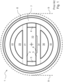
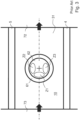
- FIG. 1 and Fig. 2 and Fig. 3 An example of a reaction chamber 1 of this type is illustrated schematically in Fig. 1 and Fig. 2 and Fig. 3 ; it extends uniformly along a longitudinal direction. It comprises a susceptor assembly comprised of four susceptor elements 2, 3, 4 and 5 that define a reaction and deposition zone 10 and that are contained in a casing 7 made of heat insulating material; the casing 7 is inserted in a quartz tube 8.
- the casing 7 is comprised of a tube 71 and two circular caps 72 and 73.
- an inductor 9 is wrapped, being adapted to heat by electromagnetic induction the elements 2, 3, 4 and 5 which are made of graphite; the inductor 9 is represented with a broken line because it is not strictly part of the reaction chamber 1.
- the inductor elements 4 and 5 are two strips and constitute the side walls of the zone 10.
- the elements 2 and 3 are two projection solids with a circular segment shaped section and with a through hole 20 and 30 having a circular segment shaped section; therefore, they are comprised of a flat plate 21 and 31 and a curved plate 22 and 32; the flat plates 21 and 31 constitute respectively the upper and lower walls of the zone 10.
- the lower wall 31 is adapted to house an assembly 6 that comprises, among other things, a support element 61 (typically rotatable during the deposition processes) adapted to support at least one substrate 62 subject to deposition; according to this example, the support element 61 can be inserted and extracted from the zone 10.
- the two caps 72 and 73 are shown as though they were closed; however, they represent openings, in particular an opening in the cap 73 for the inlet of precursor gases (see the black arrow) and an opening in the cap 72 for the outlet of exhaust gases (see the black arrow).
- the cross sections of the chamber 1 at positions P1, P2, P3, P4, P5, P6, P7 and P8 are identical (to be precise, almost identical).
- reaction chambers described and illustrated in these two patent applications had the aim, among other things, of maintaining a uniform temperature within the reaction and deposition zone (10 in Fig. 1 and Fig. 2 and Fig. 3 ) and, in particular, within the substrates subject to deposition (62 in Fig. 1 and Fig. 2 and Fig. 3 ).
- reaction chamber extends uniformly along a longitudinal direction.
- the Applicant realised that in order to obtain a desired temperature profile of the substrates subject to deposition during the deposition processes (e.g. a uniform temperature of the upper surfaces of the substrates during the deposition processes), such an equal contribution is not the best solution.
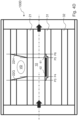
- a substrate for example made of silicon carbide is placed on the chamber support element, the reaction and deposition zone of the chamber is heated to the process temperature, hydrogen (instead of the usual mixtures of process gas) is allowed to flow into the reaction and deposition zone for a predetermined time, the reaction and deposition zone is cooled, the substrate thus treated is extracted from the reaction and deposition zone, and finally the thickness of the substrate thus treated is measured in various points; the temperature of the upper surface of the substrate (during treatment) in these various points can be detected from the respective thickness measurements there being a relationship between the "etching" speed of the hydrogen and the temperature.
- Fig. 3 The result of such indirect measurements is represented in Fig. 3 .
- the support element 61 does not rotate (and therefore the substrate 62 does not rotate either)
- the upper surface of the substrate 62 has a front zone Z1 that is colder as it is hit by the entering gases (see black arrow on the left of Fig. 3 ) in the reaction and deposition zone 10 which are relatively cold, and two side zones Z2 and Z3 which are hotter as they are close to the side walls 4 and 5 which are relatively hot.
- the support element 61 rotates during the deposition process, such temperature nonuniformity of the substrate 62 is reduced, but not completely cancelled out.
- the object of the present invention is to simply and effectively vary the contribution of the susceptor assembly to the heating of the reaction and deposition zone of the reaction chamber as a function of the longitudinal position.
- a further object of the present invention is to simply and effectively vary the contribution of the susceptor assembly to the heating of the reaction and deposition zone of the reaction chamber as a function of the transversal position.
- the subject matter of the present invention is also a reactor that uses such reaction chamber.
- alternating electrical currents are induced in the susceptor elements 2, 3, 4 and 5, especially in the elements 2 and 3 (it is to be noted, according to the present invention, that elements 4 and 5 could also be made in full or in part, of electrically insulating material and therefore provide a low contribution to the heating of the reaction and deposition zone 10).
- the most typical material for making the susceptor elements is, as known, graphite; this can be used bare or covered, for example, covered in silicon carbide or tantalum carbide.
- the induced currents follow closed paths around the hole 20; given the symmetry of the element 2, it can be assumed that each of these paths is within a plane perpendicular to the axis (see the "+" sign in Fig. 1 ) of the chamber 1; one of these planes is for example the plane of Fig. 1 .
- the currents induced in the susceptor elements create heat by the Joule effect.
- the Applicant decided to obtain heat generation of the susceptor assembly according to the longitudinal position by varying, in particular, the cross section of the susceptor element 2 as a function of the longitudinal position.
- the susceptor element with a variable cross section is similar to a projection solid, in particular a perforated projection solid.
- the main objective of such variation of the section was that of limiting or preventing the currents induced around the hole in one or more zones of the susceptor assembly.
- the Applicant decided to obtain heat generation of the susceptor assembly according to the longitudinal and/or transversal position by varying, in particular, the thickness of the susceptor element 2 as a function of the position.
- the first factor is the conduction of heat within the susceptor elements with particular regard to any heat flows in directions having a parallel component to the axis of the chamber (see "+" sign in Fig. 1 ).
- the second factor is the conduction of electrical energy within the susceptor elements with particular regard to any flows of electrical current in directions having a parallel component to the axis of the chamber (see "+" sign in Fig. 1 ).
- the embodiments of figures 4 and 5 can be considered variants of the solution of Fig. 1 and Fig. 2 and Fig. 3 .
- the examples of Fig. 4 differ from the solution of Fig. 1 and Fig. 2 and Fig. 3 only because of the configuration of the curved plate of the upper susceptor elements, i.e. the susceptor element opposite to the substrate support element; in particular, the flat plate of this susceptor element faces the substrate support element.
- the examples of Fig. 5 differ from the solution of Fig. 1 and Fig. 2 and Fig. 3 only because of the configuration of the flat plate of the upper susceptor elements, i.e. the susceptor element opposite to the substrate support element; in particular, the flat plate of this susceptor element faces the substrate support element.
- the example of Fig. 6 differs from the solution of Fig. 1 and Fig. 2 and Fig. 3 only because of the configuration of the upper susceptor element (i.e. the susceptor element opposite to the substrate support element) and is similar to a combination of the example of Fig. 4A of the example of Fig. 5A ; in general, the examples of Fig. 4 and the examples of Fig. 5 can be combined with one another.
- a plate may comprise one or more parts joined together; in particular, a plate may be obtained by joining two (or more) flat bodies having the same outline, and such two (or more bodies) can be simply overlapped or fixed to one another.
- the construction aspects can affect the behaviour of a solution; for example, if a component is obtained by joining two graphite bodies covered in silicon carbide, heat passes easily from one body to the other whereas electrical current does not pass easily from one body to the other.
- the longitudinal position P4 corresponds to the position of an end of the edge of the substrate 62; the longitudinal position P3 corresponds to the position of an end of the edge of the support element 61; the longitudinal positions P1 and P2 (distanced from one another) correspond to examples of intermediate positions between the end of the edge of the support element 61 and an end of the zone 10; the longitudinal position P5 corresponds to the position of another end of the edge of the substrate 62; the longitudinal position P6 corresponds to the position of another end of the edge of the support element 61; the longitudinal positions P7 and P8 (distanced from one another) correspond to examples of intermediate positions between the other end of the edge of the support element 61 and another end of the zone 10.
- the susceptor element 2 comprises:
- the example 100B of Fig. 4B is similar to the example 100A of Fig. 4A .
- a first curved plate 22C extends to position P3
- a second curved plate 22D extends from position P6, and between the two plates there is a volume VB.
- the example 100C of Fig. 4C is similar to the example 100A of Fig. 4A .
- a first curved plate 22E extends to position P2
- a second curved plate 22F extends from position P7, and between the two plates there is a volume VC.
- the example 100D of Fig. 4D is similar to the example 100A of Fig. 4A .
- a first curved plate 22G extends upwards to position P3 and downwards to position P4 (in particular, it is delimited longitudinally by an inclined plane)
- a second curved plate 22H extends upwards from position P6 and downwards from position P5 (in particular it is delimited longitudinally by an inclined plane)
- a volume VD between the two plates there is a volume VD.
- the example 100E of Fig. 4E is similar to the example 100A of Fig. 4A .
- a first curved plate 22L extends upwards to position P3 and downwards to position P4 (in particular, it is delimited longitudinally by an inclined plane)
- a second curved plate 22M extends from position P6 and between the two plates there is a volume VE.
- the example 100F of Fig. 4F is very similar to the example 100D of Fig. 4D .
- a first curved plate 22N and a second curved plate 22P have different radii of curvature and between the two plates there is a volume VF.
- the susceptor element 2 comprises:
- the example 100H of Fig. 5B is similar to the example 100G of Fig. 5A .
- a first flat plate S4 extends to position P3
- a second flat plate S5 extends from position P6
- a third flat plate S6 extends between position P3 and position P6 and the three plates are typically made of a single piece 21-2.
- the example 100L of Fig. 5C is similar to the example 100G of Fig. 5A .
- a first flat plate S4 extends to position P3
- a second flat plate S5 extends from position P6
- a third flat plate S3 extends between position P4 and position P
- the three plates and the two connectors are typically made of a single piece 21-3.
- the lowering of the flat plate 21-1, 21-2, 21-3, 21-4 in the examples 100G, 100H and 100L of figures 5 and in the example of the flat plate in example 600 of figures 6 is used to restrict the induced currents flowing into the intermediate zone of the susceptor element 2.
- the example 600 of figures 6 is very similar to the example 100A of Fig. 4A in relation to the curved plate 22 and to the example 100G of Fig. 5A in relation to the flat plate 21-4, and has a volume VM in the centre.
- the first plate S1 has a central lowering S7 (i.e. centred with respect to the axis of the chamber - see Fig. 6-2 ) which extends in the longitudinal direction (see Fig. 6-1 ).
- the lowering S7 is aligned with the assembly 6 (see Fig. 6-2 ); more in particular, the width of the lowering 7 corresponds to the diameter of the substrate 62.
- the lowering S7 faces the hole 20.
- the thickness of the plate S1 at the lowering S7 is greater than the thickness of the plate S3.
- the lowering S7 is used to heat the gases entering the reaction and deposition zone more (transversally) in the centre, in particular between the transverse positions D1 and D2 (symmetrical with respect to the axis of the zone 10) with respect to the sides (consider in Fig. 6-2 the position with respect to elements 4 and 5).
- a reaction chamber is used for an epitaxial reactor adapted for the deposition of semiconductor material (in particular silicon carbide) on a substrate (in particular silicon carbide); it extends in a longitudinal direction and comprises a reaction and deposition zone that extends in the longitudinal direction; this zone is defined by susceptor elements adapted to be heated by electromagnetic induction); (at least) a first susceptor element has a hole that extends in the longitudinal direction for the entire length thereof; the first susceptor element has a non-uniform cross section that depends on its longitudinal position.
- semiconductor material in particular silicon carbide
- substrate in particular silicon carbide
- susceptor elements adapted to be heated by electromagnetic induction
- a first susceptor element has a hole that extends in the longitudinal direction for the entire length thereof; the first susceptor element has a non-uniform cross section that depends on its longitudinal position.
- At least the first susceptor element typically resembles a projection solid, in particular a perforated projection solid.
- the first susceptor element has a first (longitudinal) end zone and a second (longitudinal) end zone and an intermediate (longitudinal) end zone; the first end zone and the second end zone can be equal.
- the sectional area in the intermediate zone is smaller than the sectional area in the first end zone and in the second end zone.
- the first susceptor element comprises (at least) a flat plate (that partially delimits the reaction and deposition zone) and (at least) a curved plate (that does not delimit the reaction and deposition zone) that is joined to the flat plate (similarly to the reaction chamber of Fig. 1 and Fig. 2 ); the flat plate and the curved plate surround the hole of the first susceptor element.
- a flat plate 21 is shown (which has a plurality of grooves 212) in particular of the upper susceptor element
- a curved plate 22 is shown (which has a plurality of cuts 222) in particular of the upper susceptor element; the plate 21 of Fig. 7 and the plate 22 of Fig.
- a susceptor element in particular an upper susceptor element (note the two arrows 22 in Fig. 7 ) that can also be a single piece; the reference 211 indicates the portion of the plate 21 that is not in contact with the plate 22.
- a first way of obtaining non-uniform generation of heat of the susceptor assembly envisages that the curved plate has at least one cut (see for example the cuts 222) and/or at least one hole of appropriate dimensions; the hole can be oriented radially i.e. in the perpendicular direction to the longitudinal direction of the first susceptor element; the cut can extend circumferentially (see for example the cuts 222).
- the number, width and position of the cuts 222 influence the generation of heat.
- a second way of obtaining non-uniform generation of heat of the susceptor assembly envisages the curved plate having a variable thickness.
- a third way of obtaining non-uniform generation of heat of the susceptor assembly envisages the flat plate having a variable thickness.
- Fig. 7 represents a case in which such thickness variability derives from grooves obtained on the side of the plate 21 facing towards the hole 20; the grooves 212 are rectilinear and oriented towards the width LA of the reaction chamber but, alternatively, they could be oriented for example according to the length LU of the reaction chamber.
- the number, the shape, the width, the length, the position and the orientation of the grooves influence the generation of heat.
- the first susceptor element has a first (longitudinal) end zone and a second (longitudinal) end zone and an intermediate (longitudinal) zone,
- These first embodiments can envisage a means adapted to conduct heat in the radial direction situated between the first curved plate and the second curved plate.
- the first susceptor element has a first (longitudinal) end zone and a second (longitudinal) end zone and an intermediate (longitudinal) zone,
- These second embodiments can envisage the first flat plate and/or the second flat plate having a (thin) central lowering or raising that extends in the longitudinal direction (see for example figures 6 ).
- third embodiments can combine characteristics of the first embodiments and characteristics of the second embodiments.
- the chamber according to the present invention comprises a disk-shaped support element (preferably rotatable) (consider for example reference 61) adapted to support (directly or indirectly) one or more substrates (consider for example reference 62) in the reaction and deposition zone;
- the first susceptor element can preferably be situated frontally with respect to this support element; in particular, the flat wall of the intermediate zone of the first susceptor element is situated frontally with respect to this support element. All this is valid for the examples of the figures.
- the support element can be placed at a certain distance from the third flat wall.
- the diameter of the support element 61 or of the substrate 62 can be equal to the product of the length of the reaction and deposition zone and is a factor of k1; wherein k1 is, for example, comprised between 0.3 and 0.9 or between 0.5 and 0.8.
- the diameter of the support element 61 or of the substrate 62 can be equal to the product of the width of the reaction and deposition zone and is a factor of k2; wherein k2 is, for example, comprised between 0.3 and 0.9 or between 0.5 and 0.8.
- the diameter of the support element 61 or of the substrate 62 can be equal to the product of the height of the reaction and deposition zone and is a factor of k3; wherein k3 is, for example, comprised between 0.1 and 0.3.
- the characteristic related to the height of the reaction and deposition zone can also be defined in absolute terms; in this case, the height is comprised, for example, between 10 and 100 mm or between 20 and 40 mm.
- the chamber according to the present invention comprises an inductor assembly adapted to create an electromagnetic field for heating the electromagnetic induction susceptor elements; the inductor assembly can preferably be arranged to heat differently a first (longitudinal) end zone and a second (longitudinal) end zone and a (longitudinal) intermediate zone of the first susceptor element.
- the inductor assembly can comprise a first inductor at the first (longitudinal) end zone and a second inductor at the second (longitudinal) end zone.
Landscapes
- Chemical & Material Sciences (AREA)
- Engineering & Computer Science (AREA)
- Materials Engineering (AREA)
- Metallurgy (AREA)
- Organic Chemistry (AREA)
- Chemical Kinetics & Catalysis (AREA)
- Mechanical Engineering (AREA)
- General Chemical & Material Sciences (AREA)
- Crystallography & Structural Chemistry (AREA)
- Chemical Vapour Deposition (AREA)
- Crystals, And After-Treatments Of Crystals (AREA)
Claims (14)
- Chambre de réaction pour un réacteur épitaxial adapté au dépôt de matériau semi-conducteur sur un substrat (62), qui s'étend dans une direction longitudinale et qui comprend une zone de réaction et de dépôt (10) s'étendant dans ladite direction longitudinale, dans laquelle ladite zone (10) est définie par des éléments suscepteurs adaptés pour être chauffés par induction électromagnétique, dans laquelle un premier élément suscepteur (21, 22) desdits éléments suscepteurs est opposé à un élément de support de substrat (61) de la chambre et comporte un trou (20) s'étendant dans ladite direction longitudinale sur toute sa longueur,
caractérisée en ce que
ledit premier élément suscepteur (21, 22) a une section transversale non uniforme qui dépend de sa position longitudinale. - Chambre selon la revendication 1, dans laquelle ledit premier élément suscepteur comporte une première zone d'extrémité et une seconde zone d'extrémité et une zone intermédiaire, dans laquelle la surface de section au niveau de ladite zone intermédiaire est plus petite que la surface de section au niveau de ladite première zone d'extrémité et au niveau de ladite seconde zone d'extrémité.
- Chambre selon la revendication 2, dans laquelle ladite première zone d'extrémité et ladite seconde zone d'extrémité sont égales.
- Chambre selon l'une quelconque des revendications précédentes, dans laquelle ledit premier élément suscepteur (21, 22) comprend une plaque plate (21) et une plaque incurvée (22) qui est jointe à ladite plaque plate (21), dans laquelle ladite plaque plate (21) et ladite plaque incurvée (22) entourent ledit trou (20).
- Chambre selon la revendication 4, dans laquelle ladite plaque incurvée (22) présente au moins une découpe (222) et/ou au moins un trou.
- Chambre selon la revendication 4 ou 5, dans laquelle ladite plaque incurvée a une épaisseur variable.
- Chambre selon la revendication 4 ou 5 ou 6, dans laquelle ladite plaque plate (21) a une épaisseur variable (212).
- Chambre selon la revendication 1 ou 2 ou 3, dans laquelle ledit premier élément suscepteur comporte une première zone d'extrémité et une seconde zone d'extrémité et une zone intermédiaire,- dans laquelle ladite première zone d'extrémité comprend une première plaque plate et une première plaque incurvée qui est jointe à la première plaque plate,- dans laquelle ladite seconde zone d'extrémité comprend une deuxième plaque plate et une seconde plaque incurvée qui est jointe à la deuxième plaque plate, et- dans laquelle ladite zone intermédiaire consiste en une troisième plaque plate.
- Chambre selon la revendication 8, comprenant des moyens adaptés pour conduire la chaleur dans une direction radiale, situés entre ladite première plaque incurvée et ladite seconde plaque incurvée.
- Chambre selon la revendication 1 ou 2 ou 3, dans laquelle ledit premier élément suscepteur comporte une première zone d'extrémité et une seconde zone d'extrémité et une zone intermédiaire,- dans laquelle ladite première zone d'extrémité comprend une première plaque plate avec une première épaisseur,- dans laquelle ladite seconde zone d'extrémité comprend une deuxième plaque plate d'une deuxième épaisseur, et- dans laquelle ladite zone intermédiaire comprend une troisième plaque plate avec une troisième épaisseur ;dans laquelle ladite troisième épaisseur est inférieure ou supérieure à ladite première épaisseur et à ladite deuxième épaisseur.
- Chambre selon la revendication 10, dans laquelle ladite première plaque plate et/ou ladite deuxième plaque plate présentent un abaissement central ou un soulèvement central qui se développe dans ladite direction longitudinale.
- Chambre selon l'une quelconque des revendications précédentes, comprenant un élément de support en forme de disque adapté pour supporter un ou plusieurs substrats dans ladite zone de réaction et de dépôt, dans laquelle ledit premier élément suscepteur est situé frontalement par rapport audit élément de support, en particulier ladite zone intermédiaire est située frontalement par rapport audit élément de support.
- Chambre selon l'une quelconque des revendications précédentes, comprenant un ensemble inducteur adapté pour créer un champ électromagnétique pour chauffer lesdits éléments suscepteurs à induction électromagnétique, dans laquelle ledit ensemble inducteur est agencé pour chauffer de manière différentielle une première zone d'extrémité et une seconde zone d'extrémité et une zone intermédiaire dudit premier élément suscepteur.
- Réacteur comprenant une chambre de réaction selon l'une quelconque des revendications précédentes.
Applications Claiming Priority (2)
| Application Number | Priority Date | Filing Date | Title |
|---|---|---|---|
| IT102018000011158A IT201800011158A1 (it) | 2018-12-17 | 2018-12-17 | Camera di reazione per un reattore epitassiale di materiale semiconduttore con sezione longitudinale non-uniforme e reattore |
| PCT/IB2019/058873 WO2020128653A1 (fr) | 2018-12-17 | 2019-10-17 | Chambre de réaction pour réacteur épitaxial de matériau semi-conducteur à section longitudinale non uniforme et réacteur |
Publications (2)
| Publication Number | Publication Date |
|---|---|
| EP3880863A1 EP3880863A1 (fr) | 2021-09-22 |
| EP3880863B1 true EP3880863B1 (fr) | 2023-02-15 |
Family
ID=66049441
Family Applications (1)
| Application Number | Title | Priority Date | Filing Date |
|---|---|---|---|
| EP19804841.5A Active EP3880863B1 (fr) | 2018-12-17 | 2019-10-17 | Chambre de réaction pour réacteur épitaxial de matériau semi-conducteur à section longitudinale non uniforme et réacteur |
Country Status (6)
| Country | Link |
|---|---|
| US (2) | US12435420B2 (fr) |
| EP (1) | EP3880863B1 (fr) |
| JP (1) | JP7073586B2 (fr) |
| CN (1) | CN113195780B (fr) |
| IT (1) | IT201800011158A1 (fr) |
| WO (1) | WO2020128653A1 (fr) |
Cited By (1)
| Publication number | Priority date | Publication date | Assignee | Title |
|---|---|---|---|---|
| EP4541934A2 (fr) | 2023-10-17 | 2025-04-23 | LPE S.p.A. | Appareil pour la fabrication de dispositifs semi-conducteurs |
Families Citing this family (4)
| Publication number | Priority date | Publication date | Assignee | Title |
|---|---|---|---|---|
| EP3961169B1 (fr) * | 2019-04-26 | 2025-04-16 | Kwansei Gakuin Educational Foundation | Procédé d'évaluation de distribution de température, dispositif d'évaluation de distribution de température et procédé d'évaluation de la distribution du chauffage uniforme |
| IT201900022047A1 (it) * | 2019-11-25 | 2021-05-25 | Lpe Spa | Dispositivo di supporto substrati per una camera di reazione di un reattore epitassiale con rotazione a flusso di gas, camera di reazione e reattore epitassiale |
| IT202000021517A1 (it) * | 2020-09-11 | 2022-03-11 | Lpe Spa | Metodo per deposizione cvd di carburo di silicio con drogaggio di tipo n e reattore epitassiale |
| US12270752B2 (en) * | 2022-05-23 | 2025-04-08 | Applied Materials, Inc. | EPI self-heating sensor tube as in-situ growth rate sensor |
Family Cites Families (9)
| Publication number | Priority date | Publication date | Assignee | Title |
|---|---|---|---|---|
| KR100478461B1 (ko) * | 1995-08-03 | 2005-09-05 | 에이에스엠 아메리카, 인코포레이티드 | 내부지지체를갖는프로세스챔버 |
| TW544775B (en) * | 2001-02-28 | 2003-08-01 | Japan Pionics | Chemical vapor deposition apparatus and chemical vapor deposition method |
| EP1570108B1 (fr) | 2002-12-10 | 2009-02-18 | E.T.C. Epitaxial Technology Center SRL | Systeme suscepteur |
| CN100507073C (zh) * | 2002-12-10 | 2009-07-01 | Etc外延技术中心有限公司 | 感受器系统 |
| JP4058364B2 (ja) * | 2003-03-18 | 2008-03-05 | 株式会社日立製作所 | 半導体製造装置 |
| ITMI20052498A1 (it) | 2005-12-28 | 2007-06-29 | Lpe Spa | Camera di reazione a temperatura differenziata |
| WO2008100917A1 (fr) * | 2007-02-16 | 2008-08-21 | Caracal, Inc. | Système de croissance épitaxiale pour un chauffage et un refroidissement rapide |
| ITCO20130073A1 (it) * | 2013-12-19 | 2015-06-20 | Lpe Spa | Camera di reazione di un reattore per crescite epitassiali adatta per l'uso con un dispositivo di carico/scarico e reattore |
| CN107723790B (zh) | 2016-08-12 | 2020-07-07 | 上海新昇半导体科技有限公司 | 一种外延设备、设备制作方法及外延方法 |
-
2018
- 2018-12-17 IT IT102018000011158A patent/IT201800011158A1/it unknown
-
2019
- 2019-10-17 CN CN201980083556.2A patent/CN113195780B/zh active Active
- 2019-10-17 US US17/414,763 patent/US12435420B2/en active Active
- 2019-10-17 WO PCT/IB2019/058873 patent/WO2020128653A1/fr not_active Ceased
- 2019-10-17 EP EP19804841.5A patent/EP3880863B1/fr active Active
- 2019-10-17 JP JP2021534151A patent/JP7073586B2/ja active Active
-
2025
- 2025-09-18 US US19/333,203 patent/US20260015726A1/en active Pending
Cited By (1)
| Publication number | Priority date | Publication date | Assignee | Title |
|---|---|---|---|---|
| EP4541934A2 (fr) | 2023-10-17 | 2025-04-23 | LPE S.p.A. | Appareil pour la fabrication de dispositifs semi-conducteurs |
Also Published As
| Publication number | Publication date |
|---|---|
| JP2022508364A (ja) | 2022-01-19 |
| CN113195780B (zh) | 2022-05-27 |
| JP7073586B2 (ja) | 2022-05-23 |
| WO2020128653A1 (fr) | 2020-06-25 |
| US20220074048A1 (en) | 2022-03-10 |
| EP3880863A1 (fr) | 2021-09-22 |
| IT201800011158A1 (it) | 2020-06-17 |
| US12435420B2 (en) | 2025-10-07 |
| CN113195780A (zh) | 2021-07-30 |
| US20260015726A1 (en) | 2026-01-15 |
Similar Documents
| Publication | Publication Date | Title |
|---|---|---|
| EP3880863B1 (fr) | Chambre de réaction pour réacteur épitaxial de matériau semi-conducteur à section longitudinale non uniforme et réacteur | |
| KR0160510B1 (ko) | 다구역 평면 히이터 어셈블리 및 그의 운전 방법 | |
| KR101046043B1 (ko) | 노용 다중 구역 히터 | |
| TWI619839B (zh) | Heating device for the susceptor of the CVD reactor | |
| JP2019508862A (ja) | 円筒状ヒータ | |
| US20240412988A1 (en) | Multi-zone azimuthal heater | |
| US20260027666A1 (en) | Electrostatic chuck | |
| TWM522949U (zh) | 加熱裝置 | |
| EP2610570B1 (fr) | Agencement d'élément chauffant pour four de traitement thermique sous vide | |
| KR20080079263A (ko) | 차등화된 온도의 반응 챔버 | |
| US20150361555A1 (en) | Cvd epitaxial reactor chamber with resistive heating, three channel substrate carrier and gas preheat structure | |
| TWI653697B (zh) | 用於減少熱能傳輸之基板載體及其使用及應用其之系統 | |
| JP2020098808A (ja) | 熱処理装置 | |
| EP2829155B1 (fr) | Élément de chauffage par résistance | |
| KR20190058330A (ko) | 가열식 기판 지지부 | |
| US12432820B2 (en) | Heater and production thereof | |
| KR102355535B1 (ko) | 플레이트 타입 가열장치 | |
| US3626153A (en) | Electric halide vapor heater | |
| EP2743971B1 (fr) | Dispositif de traitement thermique | |
| CN113025999A (zh) | 加热器 | |
| CN112430799A (zh) | 热蒸发坩埚和热蒸发装置 | |
| JPH0554690B2 (fr) | ||
| KR102599646B1 (ko) | 반도체 공정 설비 및 반도체 공정 설비 가열장치 | |
| KR20230063862A (ko) | 기판 처리 장치 | |
| KR20140106194A (ko) | 히터 |
Legal Events
| Date | Code | Title | Description |
|---|---|---|---|
| STAA | Information on the status of an ep patent application or granted ep patent |
Free format text: STATUS: UNKNOWN |
|
| STAA | Information on the status of an ep patent application or granted ep patent |
Free format text: STATUS: THE INTERNATIONAL PUBLICATION HAS BEEN MADE |
|
| PUAI | Public reference made under article 153(3) epc to a published international application that has entered the european phase |
Free format text: ORIGINAL CODE: 0009012 |
|
| STAA | Information on the status of an ep patent application or granted ep patent |
Free format text: STATUS: REQUEST FOR EXAMINATION WAS MADE |
|
| 17P | Request for examination filed |
Effective date: 20210528 |
|
| AK | Designated contracting states |
Kind code of ref document: A1 Designated state(s): AL AT BE BG CH CY CZ DE DK EE ES FI FR GB GR HR HU IE IS IT LI LT LU LV MC MK MT NL NO PL PT RO RS SE SI SK SM TR |
|
| DAV | Request for validation of the european patent (deleted) | ||
| DAX | Request for extension of the european patent (deleted) | ||
| GRAP | Despatch of communication of intention to grant a patent |
Free format text: ORIGINAL CODE: EPIDOSNIGR1 |
|
| STAA | Information on the status of an ep patent application or granted ep patent |
Free format text: STATUS: GRANT OF PATENT IS INTENDED |
|
| INTG | Intention to grant announced |
Effective date: 20221125 |
|
| GRAS | Grant fee paid |
Free format text: ORIGINAL CODE: EPIDOSNIGR3 |
|
| GRAA | (expected) grant |
Free format text: ORIGINAL CODE: 0009210 |
|
| STAA | Information on the status of an ep patent application or granted ep patent |
Free format text: STATUS: THE PATENT HAS BEEN GRANTED |
|
| AK | Designated contracting states |
Kind code of ref document: B1 Designated state(s): AL AT BE BG CH CY CZ DE DK EE ES FI FR GB GR HR HU IE IS IT LI LT LU LV MC MK MT NL NO PL PT RO RS SE SI SK SM TR |
|
| REG | Reference to a national code |
Ref country code: CH Ref legal event code: EP Ref country code: GB Ref legal event code: FG4D |
|
| REG | Reference to a national code |
Ref country code: DE Ref legal event code: R096 Ref document number: 602019025336 Country of ref document: DE |
|
| REG | Reference to a national code |
Ref country code: AT Ref legal event code: REF Ref document number: 1548256 Country of ref document: AT Kind code of ref document: T Effective date: 20230315 Ref country code: IE Ref legal event code: FG4D |
|
| REG | Reference to a national code |
Ref country code: SE Ref legal event code: TRGR |
|
| REG | Reference to a national code |
Ref country code: LT Ref legal event code: MG9D |
|
| REG | Reference to a national code |
Ref country code: NL Ref legal event code: MP Effective date: 20230215 |
|
| P01 | Opt-out of the competence of the unified patent court (upc) registered |
Effective date: 20230530 |
|
| REG | Reference to a national code |
Ref country code: AT Ref legal event code: MK05 Ref document number: 1548256 Country of ref document: AT Kind code of ref document: T Effective date: 20230215 |
|
| PG25 | Lapsed in a contracting state [announced via postgrant information from national office to epo] |
Ref country code: RS Free format text: LAPSE BECAUSE OF FAILURE TO SUBMIT A TRANSLATION OF THE DESCRIPTION OR TO PAY THE FEE WITHIN THE PRESCRIBED TIME-LIMIT Effective date: 20230215 Ref country code: PT Free format text: LAPSE BECAUSE OF FAILURE TO SUBMIT A TRANSLATION OF THE DESCRIPTION OR TO PAY THE FEE WITHIN THE PRESCRIBED TIME-LIMIT Effective date: 20230615 Ref country code: NO Free format text: LAPSE BECAUSE OF FAILURE TO SUBMIT A TRANSLATION OF THE DESCRIPTION OR TO PAY THE FEE WITHIN THE PRESCRIBED TIME-LIMIT Effective date: 20230515 Ref country code: NL Free format text: LAPSE BECAUSE OF FAILURE TO SUBMIT A TRANSLATION OF THE DESCRIPTION OR TO PAY THE FEE WITHIN THE PRESCRIBED TIME-LIMIT Effective date: 20230215 Ref country code: LV Free format text: LAPSE BECAUSE OF FAILURE TO SUBMIT A TRANSLATION OF THE DESCRIPTION OR TO PAY THE FEE WITHIN THE PRESCRIBED TIME-LIMIT Effective date: 20230215 Ref country code: LT Free format text: LAPSE BECAUSE OF FAILURE TO SUBMIT A TRANSLATION OF THE DESCRIPTION OR TO PAY THE FEE WITHIN THE PRESCRIBED TIME-LIMIT Effective date: 20230215 Ref country code: HR Free format text: LAPSE BECAUSE OF FAILURE TO SUBMIT A TRANSLATION OF THE DESCRIPTION OR TO PAY THE FEE WITHIN THE PRESCRIBED TIME-LIMIT Effective date: 20230215 Ref country code: ES Free format text: LAPSE BECAUSE OF FAILURE TO SUBMIT A TRANSLATION OF THE DESCRIPTION OR TO PAY THE FEE WITHIN THE PRESCRIBED TIME-LIMIT Effective date: 20230215 Ref country code: AT Free format text: LAPSE BECAUSE OF FAILURE TO SUBMIT A TRANSLATION OF THE DESCRIPTION OR TO PAY THE FEE WITHIN THE PRESCRIBED TIME-LIMIT Effective date: 20230215 |
|
| PG25 | Lapsed in a contracting state [announced via postgrant information from national office to epo] |
Ref country code: PL Free format text: LAPSE BECAUSE OF FAILURE TO SUBMIT A TRANSLATION OF THE DESCRIPTION OR TO PAY THE FEE WITHIN THE PRESCRIBED TIME-LIMIT Effective date: 20230215 Ref country code: IS Free format text: LAPSE BECAUSE OF FAILURE TO SUBMIT A TRANSLATION OF THE DESCRIPTION OR TO PAY THE FEE WITHIN THE PRESCRIBED TIME-LIMIT Effective date: 20230615 Ref country code: GR Free format text: LAPSE BECAUSE OF FAILURE TO SUBMIT A TRANSLATION OF THE DESCRIPTION OR TO PAY THE FEE WITHIN THE PRESCRIBED TIME-LIMIT Effective date: 20230516 Ref country code: FI Free format text: LAPSE BECAUSE OF FAILURE TO SUBMIT A TRANSLATION OF THE DESCRIPTION OR TO PAY THE FEE WITHIN THE PRESCRIBED TIME-LIMIT Effective date: 20230215 |
|
| PG25 | Lapsed in a contracting state [announced via postgrant information from national office to epo] |
Ref country code: SM Free format text: LAPSE BECAUSE OF FAILURE TO SUBMIT A TRANSLATION OF THE DESCRIPTION OR TO PAY THE FEE WITHIN THE PRESCRIBED TIME-LIMIT Effective date: 20230215 Ref country code: RO Free format text: LAPSE BECAUSE OF FAILURE TO SUBMIT A TRANSLATION OF THE DESCRIPTION OR TO PAY THE FEE WITHIN THE PRESCRIBED TIME-LIMIT Effective date: 20230215 Ref country code: EE Free format text: LAPSE BECAUSE OF FAILURE TO SUBMIT A TRANSLATION OF THE DESCRIPTION OR TO PAY THE FEE WITHIN THE PRESCRIBED TIME-LIMIT Effective date: 20230215 Ref country code: DK Free format text: LAPSE BECAUSE OF FAILURE TO SUBMIT A TRANSLATION OF THE DESCRIPTION OR TO PAY THE FEE WITHIN THE PRESCRIBED TIME-LIMIT Effective date: 20230215 |
|
| REG | Reference to a national code |
Ref country code: DE Ref legal event code: R097 Ref document number: 602019025336 Country of ref document: DE |
|
| PG25 | Lapsed in a contracting state [announced via postgrant information from national office to epo] |
Ref country code: SK Free format text: LAPSE BECAUSE OF FAILURE TO SUBMIT A TRANSLATION OF THE DESCRIPTION OR TO PAY THE FEE WITHIN THE PRESCRIBED TIME-LIMIT Effective date: 20230215 |
|
| PLBE | No opposition filed within time limit |
Free format text: ORIGINAL CODE: 0009261 |
|
| STAA | Information on the status of an ep patent application or granted ep patent |
Free format text: STATUS: NO OPPOSITION FILED WITHIN TIME LIMIT |
|
| 26N | No opposition filed |
Effective date: 20231116 |
|
| PG25 | Lapsed in a contracting state [announced via postgrant information from national office to epo] |
Ref country code: SI Free format text: LAPSE BECAUSE OF FAILURE TO SUBMIT A TRANSLATION OF THE DESCRIPTION OR TO PAY THE FEE WITHIN THE PRESCRIBED TIME-LIMIT Effective date: 20230215 |
|
| PG25 | Lapsed in a contracting state [announced via postgrant information from national office to epo] |
Ref country code: MC Free format text: LAPSE BECAUSE OF FAILURE TO SUBMIT A TRANSLATION OF THE DESCRIPTION OR TO PAY THE FEE WITHIN THE PRESCRIBED TIME-LIMIT Effective date: 20230215 |
|
| REG | Reference to a national code |
Ref country code: CH Ref legal event code: PL |
|
| REG | Reference to a national code |
Ref country code: BE Ref legal event code: MM Effective date: 20231031 |
|
| PG25 | Lapsed in a contracting state [announced via postgrant information from national office to epo] |
Ref country code: LU Free format text: LAPSE BECAUSE OF NON-PAYMENT OF DUE FEES Effective date: 20231017 |
|
| GBPC | Gb: european patent ceased through non-payment of renewal fee |
Effective date: 20231017 |
|
| PG25 | Lapsed in a contracting state [announced via postgrant information from national office to epo] |
Ref country code: LU Free format text: LAPSE BECAUSE OF NON-PAYMENT OF DUE FEES Effective date: 20231017 |
|
| PG25 | Lapsed in a contracting state [announced via postgrant information from national office to epo] |
Ref country code: GB Free format text: LAPSE BECAUSE OF NON-PAYMENT OF DUE FEES Effective date: 20231017 |
|
| PG25 | Lapsed in a contracting state [announced via postgrant information from national office to epo] |
Ref country code: CH Free format text: LAPSE BECAUSE OF NON-PAYMENT OF DUE FEES Effective date: 20231031 |
|
| PG25 | Lapsed in a contracting state [announced via postgrant information from national office to epo] |
Ref country code: GB Free format text: LAPSE BECAUSE OF NON-PAYMENT OF DUE FEES Effective date: 20231017 Ref country code: FR Free format text: LAPSE BECAUSE OF NON-PAYMENT OF DUE FEES Effective date: 20231031 Ref country code: CH Free format text: LAPSE BECAUSE OF NON-PAYMENT OF DUE FEES Effective date: 20231031 |
|
| PG25 | Lapsed in a contracting state [announced via postgrant information from national office to epo] |
Ref country code: BE Free format text: LAPSE BECAUSE OF NON-PAYMENT OF DUE FEES Effective date: 20231031 |
|
| PG25 | Lapsed in a contracting state [announced via postgrant information from national office to epo] |
Ref country code: IE Free format text: LAPSE BECAUSE OF NON-PAYMENT OF DUE FEES Effective date: 20231017 |
|
| PG25 | Lapsed in a contracting state [announced via postgrant information from national office to epo] |
Ref country code: IE Free format text: LAPSE BECAUSE OF NON-PAYMENT OF DUE FEES Effective date: 20231017 |
|
| PG25 | Lapsed in a contracting state [announced via postgrant information from national office to epo] |
Ref country code: BG Free format text: LAPSE BECAUSE OF FAILURE TO SUBMIT A TRANSLATION OF THE DESCRIPTION OR TO PAY THE FEE WITHIN THE PRESCRIBED TIME-LIMIT Effective date: 20230215 |
|
| PG25 | Lapsed in a contracting state [announced via postgrant information from national office to epo] |
Ref country code: BG Free format text: LAPSE BECAUSE OF FAILURE TO SUBMIT A TRANSLATION OF THE DESCRIPTION OR TO PAY THE FEE WITHIN THE PRESCRIBED TIME-LIMIT Effective date: 20230215 |
|
| PG25 | Lapsed in a contracting state [announced via postgrant information from national office to epo] |
Ref country code: CY Free format text: LAPSE BECAUSE OF FAILURE TO SUBMIT A TRANSLATION OF THE DESCRIPTION OR TO PAY THE FEE WITHIN THE PRESCRIBED TIME-LIMIT; INVALID AB INITIO Effective date: 20191017 |
|
| PG25 | Lapsed in a contracting state [announced via postgrant information from national office to epo] |
Ref country code: HU Free format text: LAPSE BECAUSE OF FAILURE TO SUBMIT A TRANSLATION OF THE DESCRIPTION OR TO PAY THE FEE WITHIN THE PRESCRIBED TIME-LIMIT; INVALID AB INITIO Effective date: 20191017 |
|
| PG25 | Lapsed in a contracting state [announced via postgrant information from national office to epo] |
Ref country code: TR Free format text: LAPSE BECAUSE OF FAILURE TO SUBMIT A TRANSLATION OF THE DESCRIPTION OR TO PAY THE FEE WITHIN THE PRESCRIBED TIME-LIMIT Effective date: 20230215 |
|
| PGFP | Annual fee paid to national office [announced via postgrant information from national office to epo] |
Ref country code: DE Payment date: 20251029 Year of fee payment: 7 |
|
| PGFP | Annual fee paid to national office [announced via postgrant information from national office to epo] |
Ref country code: IT Payment date: 20251021 Year of fee payment: 7 |
|
| PGFP | Annual fee paid to national office [announced via postgrant information from national office to epo] |
Ref country code: SE Payment date: 20251027 Year of fee payment: 7 |
|
| PGFP | Annual fee paid to national office [announced via postgrant information from national office to epo] |
Ref country code: CZ Payment date: 20251007 Year of fee payment: 7 |