EP3880909B1 - Zylinder für antriebsmechanismus - Google Patents
Zylinder für antriebsmechanismus Download PDFInfo
- Publication number
- EP3880909B1 EP3880909B1 EP19808914.6A EP19808914A EP3880909B1 EP 3880909 B1 EP3880909 B1 EP 3880909B1 EP 19808914 A EP19808914 A EP 19808914A EP 3880909 B1 EP3880909 B1 EP 3880909B1
- Authority
- EP
- European Patent Office
- Prior art keywords
- rotating body
- cylinder
- cam
- thrust
- cavity
- Prior art date
- Legal status (The legal status is an assumption and is not a legal conclusion. Google has not performed a legal analysis and makes no representation as to the accuracy of the status listed.)
- Active
Links
Images


Classifications
-
- E—FIXED CONSTRUCTIONS
- E05—LOCKS; KEYS; WINDOW OR DOOR FITTINGS; SAFES
- E05B—LOCKS; ACCESSORIES THEREFOR; HANDCUFFS
- E05B47/00—Operating or controlling locks or other fastening devices by electric or magnetic means
- E05B47/06—Controlling mechanically-operated bolts by electro-magnetically-operated detents
- E05B47/0611—Cylinder locks with electromagnetic control
- E05B47/0615—Cylinder locks with electromagnetic control operated by handles, e.g. by knobs
-
- E—FIXED CONSTRUCTIONS
- E05—LOCKS; KEYS; WINDOW OR DOOR FITTINGS; SAFES
- E05B—LOCKS; ACCESSORIES THEREFOR; HANDCUFFS
- E05B47/00—Operating or controlling locks or other fastening devices by electric or magnetic means
- E05B47/06—Controlling mechanically-operated bolts by electro-magnetically-operated detents
- E05B47/0611—Cylinder locks with electromagnetic control
- E05B47/0638—Cylinder locks with electromagnetic control by disconnecting the rotor
- E05B47/0642—Cylinder locks with electromagnetic control by disconnecting the rotor axially, i.e. with an axially disengaging coupling element
-
- E—FIXED CONSTRUCTIONS
- E05—LOCKS; KEYS; WINDOW OR DOOR FITTINGS; SAFES
- E05B—LOCKS; ACCESSORIES THEREFOR; HANDCUFFS
- E05B15/00—Other details of locks; Parts for engagement by bolts of fastening devices
- E05B15/04—Spring arrangements in locks
- E05B2015/0448—Units of springs; Two or more springs working together
-
- E—FIXED CONSTRUCTIONS
- E05—LOCKS; KEYS; WINDOW OR DOOR FITTINGS; SAFES
- E05B—LOCKS; ACCESSORIES THEREFOR; HANDCUFFS
- E05B47/00—Operating or controlling locks or other fastening devices by electric or magnetic means
- E05B47/0001—Operating or controlling locks or other fastening devices by electric or magnetic means with electric actuators; Constructional features thereof
- E05B2047/0014—Constructional features of actuators or power transmissions therefor
- E05B2047/0018—Details of actuator transmissions
- E05B2047/0026—Clutches, couplings or braking arrangements
- E05B2047/0031—Clutches, couplings or braking arrangements of the elastic type
-
- E—FIXED CONSTRUCTIONS
- E05—LOCKS; KEYS; WINDOW OR DOOR FITTINGS; SAFES
- E05B—LOCKS; ACCESSORIES THEREFOR; HANDCUFFS
- E05B47/00—Operating or controlling locks or other fastening devices by electric or magnetic means
- E05B2047/0048—Circuits, feeding, monitoring
- E05B2047/0057—Feeding
- E05B2047/0058—Feeding by batteries
-
- E—FIXED CONSTRUCTIONS
- E05—LOCKS; KEYS; WINDOW OR DOOR FITTINGS; SAFES
- E05B—LOCKS; ACCESSORIES THEREFOR; HANDCUFFS
- E05B47/00—Operating or controlling locks or other fastening devices by electric or magnetic means
- E05B47/0001—Operating or controlling locks or other fastening devices by electric or magnetic means with electric actuators; Constructional features thereof
- E05B47/0012—Operating or controlling locks or other fastening devices by electric or magnetic means with electric actuators; Constructional features thereof with rotary electromotors
Definitions
- the present invention relates to a cylinder, in particular an electronic cylinder, for driving mechanism.
- cylinders typically of standardized dimensions, which are coupled to driving mechanisms, typically frame locks or other mechanisms such as switches for the control of automatic devices (e.g. motors for opening/closing gates or doors).
- driving mechanisms typically frame locks or other mechanisms such as switches for the control of automatic devices (e.g. motors for opening/closing gates or doors).
- a cylinder for driving mechanisms can typically comprise a main body (also called stator) on which there is rotatably fixed a cam (commonly named tongue) having a protruding portion.
- the cam which typically serves to drive the driving mechanism to which the cylinder is applied, is mechanically couplable to a rotating body (commonly known as plug), housed in the main body, for being able to drive the driving mechanism after a rotation of the rotating body.
- cylinders for driving mechanisms called electric or electronic, i.e. cylinders containing, in addition to or in substitution of mechanical blocking mechanisms mechanically driveable by conventional keys or the like, at least one blocking mechanism, typically comprising at least one electric power supplier and one actuator (e.g. an electromagnet or an electric motor), which is usually operated on the basis of the result of an electronic identification.
- the electronic identification involves the reading, by an access control system, of digital data relating to access rights contained in an electronic key (such as an electronic card, a smartphone or other wireless device, or a device physically connectable to the access control system through a suitable entrance).
- EP2706172 and EP2706173 describe known electronic cylinder for driving mechanisms.
- the Applicant has found that the known electronic cylinders for driving mechanisms have some drawbacks and/or can be improved in some aspects.
- Object of the present invention is therefore to provide an electronic cylinder for driving mechanisms which does not require complicated operations and/or procedures for the assembly and/or the installation and/or the maintenance, such as the replacement of the electric batteries
- the invention relates to a cylinder for driving mechanisms according to claim 1.
- the combination of the aforesaid features in particular the presence of the electric power supplier (entirely) housed inside the handling body and the presence of the access opening to the supplier realized on a face of the handling body facing away from the cam and distal from the latter and/or on a surface of the handling body having (substantially) longitudinal development, i.e.
- the lateral surface of the handling body realizes an electronic cylinder for driving mechanisms which does not require complex maintenance operations and/or procedures, since the aforementioned access to the electric power supplier allows to replace the supplier itself (if exhausted and/or in general no longer functioning) without requiring the disassembly and the reassembly of the handling body from the rest of the cylinder and without the need for specifically dedicated tools (such as for example in the aforementioned EP2706172 and EP2706173 ).
- reversibly referred to a process/operation it is meant a process/operation which does not destroy or damage a device (or parts thereof) on which the process/operation is performed, i.e. that the process/operation can be performed not destructively on the device so that it can be repeated at will and such that its effect can be cancelled without consequences for the device itself.
- said electric power supplier comprises one or more accumulators, for example electric batteries or capacitors.
- the handling body comprises a removable cover for closing said opening and protecting the electric power supplier.
- said electric power supplier is housed in an end portion of said handling body distal from said cam. In this way the insertion and/or the extraction of the electric power supplier is facilitated.
- said cylinder comprises a command and control unit mainly, more preferably entirely, housed inside said handling body and electrically connected to said electric power supplier. In this way the electric contacts of the command unit remain confined inside the handling body
- said electric power supplier occupies a position (longitudinally) farther from said cam with respect to said command and control unit.
- said command and control unit is programmed and configured to receive as an input a signal (preferably a wireless signal) identifying an access right and for actuating said actuator on the basis of a verification of said signal identifying an access right.
- a signal preferably a wireless signal
- said actuator comprises an electric motor electrically connected to said electric power supplier and to said command and control unit.
- an electromagnet which typically continues to consume current for as long as the thrust element is driven (with a consequent reduction in the life of the accumulator/s)
- the electric motor can provide for the driving of the electronic cylinder with a lower overall consumption of electric power.
- said actuator (preferably said motor) is at least partially (more preferably mainly) housed in said handling body.
- said structure of the cylinder is simplified since it does not need for electric contacts between the handling body and the rest of the cylinder for connecting the motor to the electric power supplier and/or to the command and control unit (such as for example in EP2706172 and EP2706173 ).
- the present feature allows to free space inside the rotating body, thus loosening the design constraints.
- first element inside of a second element it is meant that more than 50% (preferably more than 60% or 70%) of the overall volume of the first element is enclosed in the second element.
- Said actuator is a linear actuator acting along said longitudinal direction. In this way it is possible to adapt the electric driving of the cylinder to the logic and to the components of a purely mechanical driving cylinder (as described below).
- Said actuator comprises a thrust element (a rod) having a main development direction along said axis of rotation, wherein said actuator is structured to rectilinearly displace said thrust element from an at-rest position distal from the cam to a thrust position proximal to the cam.
- a thrust element a rod
- said actuator is structured to rectilinearly displace said thrust element from an at-rest position distal from the cam to a thrust position proximal to the cam.
- Said thrust element is mechanically connected to said coupling element in such a way that a displacement of said thrust element from said at-rest position to said thrust position gives to said coupling element a thrust force towards said cam or towards said rotating body.
- the driving of the thrust element allows the coupling between the cam and the rotating body (if the rotating body is correctly angularly aligned with the cam).
- said cylinder comprises a first elastic element (e.g. a spring) operatively interposed between said coupling element and said thrust element and structured to oppose an (increasing) elastic reaction to a (increasing) displacement of said thrust element from said at-rest position to said thrust position.
- a first elastic element e.g. a spring
- the first elastic element keeps in thrust the coupling element towards the cam (or towards the rotating body), allowing the coupling between the cam and the rotating body, if there is a correct angular alignment between the two aforesaid elements.
- the first elastic element keeps in thrust the coupling element against an abutment wall of the cam (or of the rotating body) avoiding at the same time an effort by the motor (which instead would occur in an alternative embodiment of the invention wherein the thrust element is rigidly connected to the coupling element).
- the coupling element can assume the coupling position (in which, for example, suitable protuberances of the coupling element engage corresponding seats made in the cam and in the rotating body) and thus achieve the coupling between the cam and the rotating body.
- the first elastic element tends to bring the thrust element back to the at-rest position.
- said cylinder is structured and programmed to maintain said thrust element in said thrust position for a time interval (preferably definable at will), more preferably without electric power consumption by the actuator.
- a time interval preferably definable at will
- the thrust on the coupling element is maintained, and therefore the possibility of driving the driving mechanism to which the cylinder is applied, for the time necessary and established at will by the user, preferably without power consumption and therefore without effects on the life of the power supplier.
- said cylinder is structured and programmed so that, after said time interval, the motor ceases to give to said thrust element any force (including bind reaction forces) having longitudinal direction directed towards said cam. In this way, terminated the time interval, the motor stops acting on the thrust element, which is free to return to the at-rest position without further action by the motor and therefore without further electric power consumption (the motor consumes electric power only in the displacement of the thrust element from the at-rest position to the thrust position).
- said cylinder comprises a second elastic element (e.g. a spring) operatively interposed between said main body and said coupling element and structured to oppose an (increasing) elastic reaction to a (increasing) displacement of said coupling element from said decoupling position to said coupling position.
- a second elastic element e.g. a spring
- the second elastic element tends to bring the coupling element back to the decoupling position, preventing the driving of the driving mechanism by rotation of the rotating body.
- said first and/or second elastic element are compression springs, more preferably equal to each other, and arranged along said longitudinal direction at opposite sides of said coupling element. In this way the elastic reactions of the first and of the second elastic elements are suitably oriented.
- said first and/or second elastic element have a respective degree of preloading in a closing configuration of the cylinder in which said thrust element is in the at-rest position (and said coupling element is in the decoupling position). In this way it is ensured that the elastic elements correctly act in all the configurations of the cylinder even in the face of manufacturing tolerances.
- a degree of preloading of said second elastic element is greater than a degree of preloading of said first elastic element. In this way it is reduced the risk that the coupling element mistakenly remains in the coupling position even in absence of further external forces acting on the coupling element.
- said cylinder comprises a further rotating body rotatably housed in a further cavity of the main body realized at the opposite side of said cam with respect to said cavity, and having a respective axis of rotation coinciding with said axis of rotation of the rotating body.
- said further rotating body is firmly and rigidly coupled to said cam to rotate rigidly with said cam about said axis of rotation. In this way the rotation of the further rotating body always causes a driving of the driving mechanisms.
- said rotating body and said further rotating body comprise a respective cavity having (substantially) longitudinal development.
- said cylinder comprises a further handling body at longitudinally opposite side with respect to said handling body and structured to rotate said cam about said axis of rotation at least when said coupling element is in said coupling position. In this way it is possible to drive the driving mechanisms even at opposite side with respect to the handling body.
- said handling body is (firmly) fixed to said rotating body to rotate rigidly with said rotating body about said axis of rotation.
- said further handling body is (firmly) fixed to said further rotating body to rotate rigidly with said further rotating body about said axis of rotation.
- said handling body is (firmly) fixed to said further rotating body to rotate rigidly with said further rotating body about said axis of rotation.
- said further handling body is (firmly) fixed to said rotating body to rotate rigidly with said rotating body about said axis of rotation.
- the cylinder according to the last two embodiments can be advantageously mounted so that the handling body can be gripped respectively from the outside (in the first embodiment) or from the inside (in the second embodiment) of an environment whose access is controlled by a frame (or in general another access barrier device) on which a driving mechanism comprising the cylinder is mounted.
- brackets refer preferably to the aforesaid second embodiment while the text outside parenthesis refers preferably to the aforesaid first embodiment.
- said cavity of said rotating body comprises a first mouth placed at one end of said rotating body (or of said further rotating body) distal from said cam, said first mouth being facing towards (and preferably engaged by) said actuator.
- said cavity of said rotating body comprises a second mouth placed at one end of said rotating body (or of said further rotating body) proximal to said cam, said second mouth being facing towards, and engaged by, said coupling element. In this way, a connection channel between the actuator and the coupling element is made inside the rotating body (or the further rotating body).
- said thrust element in said thrust position develops at least partially inside said cavity of said rotating body (or of said further rotating body).
- said first elastic element is housed in said cavity of said rotating body (or of said further rotating body) and comprises a first end in contact with said coupling element and a second end structured to receive a thrust force from said thrust element. In this way it is possible to transfer to the coupling element the thrust force imparted by the thrust element, adapting at the same time the cylinder to the typical operating logic of a purely mechanical driving cylinder, since there are maintained the coupling element and its logic of coupling the rotating body to the cam.
- said cavity of said further rotating body comprises a mouth placed at one end of said further rotating body (or of said rotating body) proximal to said cam, said mouth being facing towards, and engaged by, said coupling element (at least when in the coupling position).
- said second elastic element is housed in said cavity of said further rotating body (or of said rotating body). In this way the second elastic element is suitably placed to impart an elastic reaction to said coupling element to bring the coupling element from the coupling position to the decoupling position, once all the further external forces acting on the coupling element (e.g. the thrust force of the thrust element) have been cancelled.
- said cylinder comprises a contact body interposed between said thrust element and said first elastic element.
- the present invention includes any type of electronic cylinder for driving mechanisms, for example electronic whole cylinder with a single actuator (wherein the cylinder comprises on one side an electronic driving and on the other a manual driving, as shown below in the first embodiment), electronic whole cylinder with a double actuator (not shown, wherein the cylinder comprises an electronic driving on both sides), electronic half cylinder (not shown, wherein the cylinder comprises an electronic driving on one side and no driving on the other side), or hybrid cylinder (wherein the cylinder comprises on one side an electronic driving and on the other a mechanical key driving, as shown in the second embodiment), and of any shape, such as for example the European cylinder shape exemplarily shown below, or, not shown, oval, round, etc.
- any shape such as for example the European cylinder shape exemplarily shown below, or, not shown, oval, round, etc.
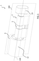
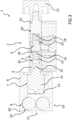
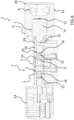
- the sections shown in figures 2 and 3 , for the first embodiment, and 5 and 6, for the second embodiment, are taken on a longitudinal median plane 200 (shown, for the first embodiment, in figure 1 ) of a cylinder 1 according to the present invention.
- the longitudinal plane 200 is preferably a plane of substantial geometrical symmetry for the cylinder 1 (e.g. except for minor asymmetries present in the second embodiment, such as, for example, the seat 51, the blocking mechanism associated with the additional rotating body 50, and the helical plane coupling system of the thrust body 52, better described below).
- a cylinder for driving mechanisms comprising a main body 2 having a cavity 3, a rotating body 4 rotatably housed in the cavity 3 and having an axis of rotation 100 along a longitudinal development direction of the cylinder 1, and a cam 5, rotatably fixed to the main body 2 (in a suitable notch thereof) and selectively couplable to the rotating body 4 to rotate about the axis of rotation 100 rigidly with the rotating body 4.
- the cylinder 1 comprises a coupling element 6 (in the shown examples consisting of a butterfly body with two diametrically opposed radial prominences) structured to alternatively assume a coupling position in which it couples the cam 5 with the rotating body 4 (e.g. shown in figures 3 and 6 ) and a decoupling position (e.g. shown in figures 2 and 5 ) in which it does not couple the cam 5 with the rotating body 4.
- a coupling element 6 in the shown examples consisting of a butterfly body with two diametrically opposed radial prominences structured to alternatively assume a coupling position in which it couples the cam 5 with the rotating body 4 (e.g. shown in figures 3 and 6 ) and a decoupling position (e.g. shown in figures 2 and 5 ) in which it does not couple the cam 5 with the rotating body 4.
- the cylinder 1 comprises an actuator 7 structured to move the coupling element 6 from the decoupling position to the coupling position.
- the cylinder 1 comprises an electric power supplier 8, for example consisting of one or more batteries as shown, electrically connected to the actuator 7.
- the cylinder 1 comprises a handling body 9 rotatably fixed to the main body 2 and structured to rotate the cam 5 about the axis of rotation 100 at least in the opening configuration of the cylinder 1 in which the coupling element is in the coupling position.
- the handling body rotates the cam 5 (only) when the cylinder is in the opening configuration (shown in fig. 3 ).
- the handling body 9 rotates the cam 5 in any configuration of the cylinder 1, the gripping body being integral with the cam 5 (through the further rotating body described below).
- the electric power supplier 8 is, exemplarily entirely, housed inside the handling body 9, exemplarily in a seat placed in a terminal end portion 33 of the handling body 9 distal from the cam 5.
- the handling body 9 comprises an access opening 10 to the electric power supplier 8 configured to allow reversible extraction/insertion of the electric power supplier 8 through the opening itself.
- the opening 10 is realized on a face 11 of the handling body 9 facing away from, and distal from, the cam 5.
- the opening 10 can be realized on a surface 12 of the handling body 9 having a substantially longitudinal development.
- the handling body preferably comprises a removable cover 40 for closing the opening 10 and protecting the electric power supplier 8 (when positioned in the seat).
- the cylinder 1 comprises a command and control unit 13 (shown in the figures in purely schematic way) entirely housed inside the handling body 9 and electrically connected to the electric power supplier 8.
- the electric power supplier 8 occupies a position longitudinally farther from the cam 5 with respect to the command and control unit 13.
- the unit 13 is longitudinally interposed between the electric power supplier 8 and the actuator 7 or (not shown) it can be placed longitudinally adjacent to the actuator 7, in a dedicated notch obtained on the handling body.
- command and control unit 13 is programmed and configured to receive as an input a signal identifying an access right (preferably a wireless signal for example RFID, Bluetooth, infrared or Wifi) emitted by an identification device (not shown, for example a smartphone, an electronic card, a remote control, etc., suitably programmed) and for actuating the actuator 7 on the basis of a verification of the signal identifying the access right.
- a signal identifying an access right preferably a wireless signal for example RFID, Bluetooth, infrared or Wifi
- an identification device not shown, for example a smartphone, an electronic card, a remote control, etc., suitably programmed
- the actuator 7 comprises an electric motor 14, electrically connected to the electric power supplier 8 and to the command and control unit 13 and exemplarily mainly housed in the handling body 9.
- the motor 14 is an electric motor PPML20C24 marketed by PrimoPal TM .
- the actuator 7 is a linear actuator acting along the longitudinal direction, comprising a thrust element 15 (a rod) having a main development direction along the axis of rotation 100, wherein the motor 14 is structured to rectilinearly displace the thrust element 15 from an at-rest position ( figures 2 and 5 ) distal from the cam 5 to a thrust position proximal to the cam ( figures 3 and 6 ).
- the cylinder 1 comprises a first elastic element 16 (exemplarily a spring) operatively interposed between the coupling element 6 and the thrust element 15.
- a second elastic element 18 exemplarily a spring operatively interposed between the main body 2 and the coupling element 6.
- first 16 and the second elastic element 18 are compression springs equal to each other and arranged along the longitudinal direction at opposite sides of the coupling element 6.
- the cylinder 1 comprises a further rotating body 19 rotatably housed in a further cavity 20 of the main body 2 realized at the opposite side of the cam 5 with respect to the cavity 3, and having a respective axis of rotation coinciding with the axis of rotation 100 of the rotating body 4.
- the further rotating body 19 is firmly and rigidly coupled to the cam 5 to rotate rigidly with the cam 5 about the axis of rotation 100.
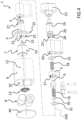
- the coupling of the further rotatable body 19 with the cam 5 is realized through a lap joint consisting of (as shown in figure 4 ) two flat faces realized at one end of the further rotating body (which supports the cam in cooperation with one end of the rotating body 4) and shaped to match with an internal profile of the cam itself.
- Exemplarily the rotating body 4 and the further rotating body 19 comprise a respective cavity 21, 22 having a longitudinal development.
- the cylinder 1 comprises a further handling body 23 rotatably fixed to the main body 2 at longitudinally opposite side with respect to said handling body 9 and structured to rotate the cam 5 about the axis of rotation 100 at least in an opening configuration of the cylinder 1.
- the handling body 9 is firmly fixed to the rotating body 4 to rotate rigidly with the rotating body 4 about the axis of rotation 100 and the further handling body 23 is firmly fixed to the further rotating body 19 to rotate rigidly with the further rotating body 19 about the axis of rotation 100. Therefore, the rotation of the further handling body 23 triggers the rotation of the cam 5 for any configuration of the cylinder.
- the handling body 9 is firmly fixed to the further rotating body 19 to rotate rigidly with the further rotating body 19 about the axis of rotation 100 and the further handling body 23 is firmly fixed to the rotating body 4 to rotate rigidly with the rotating body 4 about the axis of rotation 100. Therefore, the rotation of the further handling body 23 triggers the rotation of the cam 5 only in the two opening configurations of the cylinder in which a respective one of the two coupling elements 6 and 6' is in the coupling position.
- the cavity 21 of the rotating body 4 comprises a first mouth 24 placed at one end 25 of the rotating body 4 distal from the cam 5, the first mouth 24 being facing towards, and engaged by, the actuator 7 and a second mouth 26 placed at one end 27 of the rotating body 4 proximal to the cam 5, the second mouth 26 being facing towards, and engaged by, the coupling element 6.
- the cavity 22 of the further rotating body 19 comprises a first mouth 24 placed at one end 25 of the further rotating body 19 distal from the cam 5, the first mouth 24 being facing towards, and engaged by, the actuator 7 and a second mouth 26 placed at one end 27 of the further rotating body 19 proximal to the cam 5, the second mouth 26 being facing towards, and engaged by, the coupling element 6.
- the thrust element 15 in the thrust position develops at least partially inside the cavity 21 of the rotating body 4 and the first elastic element 16 is housed in the cavity 21 of the rotating body 4 and comprises a first end 34 in contact with the coupling element 6 and a second end 35 which receives a thrust force from the thrust element 15 by interposition of a contact body 30.
- the thrust element 15 in the thrust position develops at least partially inside the cavity 22 of the further rotating body 19 and the first elastic element 16 is housed in the cavity 22 of the further rotating body 19 and comprises a first end 34 in contact with the coupling element 6 and a second end 35 which receives a thrust force from the thrust element 15 by a contact body.
- the cavity 22 of the further rotating body 19 comprises a mouth 28 placed at one end 29 of the further rotating body 19 proximal to the cam 5, the mouth 28 being facing towards, and engaged by, the coupling element 6.
- the second elastic element 18 is housed in the cavity 22 of the further rotating body 19.
- the cavity 21 of the rotating body 4 comprises a mouth 28 placed at one end 29 of the rotating body 4 proximal to the cam 5, the mouth 28 facing towards the coupling element 6.
- the second elastic element 18 is housed in the cavity 21 of the rotating body 4.
- the further handling body houses inside itself an additional rotating body 50, having a seat 51 shaped for the insertion of a mechanical key (not shown), and a blocking mechanism with mechanical coding structured to prevent (in absence of a key having a correct coding) a rotation of the additional rotating body 50 with respect to the further handling body.
- the blocking mechanism allows the rotation of the additional rotating body if a key having the correct coding is inserted.
- the rotation of the additional rotating body 50 causes the advancement of a thrust body 52 (by a coupling with a helical plane formed in the thrust body) which imparts a thrust force to a further coupling element 6', which, in case of correct angular alignment with the cam, moves to a respective coupling position (not shown) to couple the rotating body 4 to the cam 5, so that a rotation of the further handling body 23 determines a rotation of the cam 5 (further opening configuration).
- the cylinder 1 comprises a respective elastic open ring 31 (e.g. of the "Seeger” type) for the rotating body 4 and for the further rotating body 19.
- a respective elastic open ring 31 e.g. of the "Seeger” type
- the cylinder 1 can be mounted in a lock for a frame placed to control the access to a specific circumscribed environment.
- the cylinder of the first embodiment can be advantageously used in frames that control the access to interiors in an environment/building (such as for example doors of offices, warehouses, departments within the same building, for example a factory or an hospital).
- the handling body 9 can be advantageously placed externally to the specific circumscribed interior and it allows the access to this interior only to users in possession of the access authorization.
- the further handling body 23 is placed on the opposite side, i.e. on the internal side, and it allows, for any configuration of the cylinder, through a rotation thereof, the opening of the lock, allowing the exit from the circumscribed interior.
- the cylinder of the second embodiment can advantageously be used in frames that divide interior spaces from the outside (such as for example the entrance door of a house or building).
- the handling body 9 can advantageously be placed inside the interior space, where it is safer from break-in and/or tampering attempts, and it allows with its rotation, for any configuration of the cylinder, the opening of the lock.
- the opening of the lock from the outside can instead be carried out by rotating the additional handling body 23 when the cylinder is in one of the two opening configurations (one of which shown in fig. 6 ).
- the coupling element 6 (and the possible further element 6') is in the decoupling position and the thrust element 15 (and the possible thrust body 52) is in the at-rest position.
- the first 16 and the second elastic element 18 have a respective degree of preloading wherein the degree of preloading of the second elastic element 18 is greater than the degree of preloading of the first elastic element 16.
- Exemplarily the greater degree of preloading of the second elastic element 18 is achieved housing the second elastic element 18 in a cavity (which corresponds to the cavity 22 for the first embodiment and to the cavity 21 for the second embodiment) having a longitudinal dimension about 0.05 mm smaller than a longitudinal dimension of the cavity (which corresponds to the cavity 21 for the first embodiment and to the cavity 22 for the second embodiment) wherein the first elastic element 16 is housed.
- a rotation of the handling body 9 (first embodiment) or of the further handling body 23 (second embodiment) is free, i.e. without a corresponding rotation of the cam 5, since the rotating body 4, integral with respectively the handling body 9 or the further handling body 23 is decoupled from the cam 5.
- the command and control unit 13 In presence of a signal identifying an access right, this signal is received and processed by the command and control unit 13 in order to verify a correct access authorization. In case of positive result, the command and control unit 13 commands the actuator 7, for example the motor 14, so that the thrust element 15 is moved from the at-rest position to the thrust position. The thrust element 15, through the contact body 30 and the first elastic element 16, generates a thrust force on the coupling element 6 towards the cam 5.
- Each of the cam 5 and the rotating body 4 has a pair of seats with longitudinal development, diametrically opposed with respect to the axis of rotation 100 and shaped to be engaged by the radial prominences of the coupling element 6.
- the first elastic element 16 keeps the coupling element 6 in thrust against an abutment wall 17 of the cam 5 (first embodiment), or an abutment wall 32 of the rotating body 4 (second embodiment), at the same time avoiding an effort by the motor 14 (which would instead occur in case of a rigid connection between the thrust element 15 and the coupling element 6).
- the coupling element 6 is free to reach the coupling position (e.g. it moves towards the cam in the first embodiment or towards the rotating body in the second embodiment) thus achieving the coupling between the cam 5 and the rotating body 4 (opening configuration shown in figures 3 and 6 ).
- a rotation of the handling body 9 in the first embodiment, or of the further handling body 23 in the second embodiment determines a rotation of the cam 5 and therefore an opening of the lock.
- the cylinder 1 (more preferably the actuator comprising the motor 14) is structured and programmed to keep the thrust element 15 in the thrust position for a time interval definable at will (for example from few seconds to several hours) and without electric power consumption. In this condition, when the cylinder is in the opening configuration the actuator overcomes the elastic reaction force of the second elastic element 18, which remains compressed.
- the cylinder 1 is preferably structured and programmed so that, terminated the time interval, the motor 14 ceases to impart to the thrust element 15 any force (including bind reaction forces) having longitudinal direction directed towards the cam 5.
- the first 16 and the second elastic element 18, structured to oppose a respective increasing elastic reaction to an increasing displacement respectively of the thrust element 15 from the at-rest position to the thrust position and of the coupling element 6 from the uncoupling position to the coupling position mutually cooperate to bring the thrust element 15 and the coupling element 6 respectively back to the at-rest and to the decoupling positions, bring the cylinder back to the closing configuration.
Landscapes
- Physics & Mathematics (AREA)
- Electromagnetism (AREA)
- Connection Of Motors, Electrical Generators, Mechanical Devices, And The Like (AREA)
- Lock And Its Accessories (AREA)
- Actuator (AREA)
- Vehicle Body Suspensions (AREA)
- Jib Cranes (AREA)
Claims (14)
- Zylinder (1) für Antriebsmechanismen, wobei der Zylinder einen Hauptkörper (2) mit einer Kavität (3), einen drehbaren Körper (4), der in besagter Kavität (3) drehbar gelagert ist und eine Drehachse (100) entlang einer längsverlaufenden Entwicklungsrichtung des Zylinders (1) hat, und eine Nocke (5) umfasst, die drehbar am Hauptkörper (2) befestigt ist und selektiv mit dem drehbaren Körper (4) gekuppelt werden kann, um sich starr mit dem drehbaren Körper (4) um besagte Drehachse (100) zu drehen, wobei der Zylinder (1) umfasst:• ein Kupplungselement (6), das strukturiert ist, um abwechselnd eine Kupplungsposition einzunehmen, in der es die Nocke (5) mit dem drehbaren Körper (4) kuppelt, und eine Entkopplungsposition, in der es die Nocke (5) nicht mit dem drehbaren Körper (4) kuppelt,• einen Aktuator (7), der strukturiert ist, um das Kupplungselement (6) von der Entkopplungsposition in die Kupplungsposition zu bewegen,• einen elektrischen Energieversorger (8), der elektrisch mit dem Aktuator (7) verbunden ist,• einen Handhabungskörper (9), der drehbar am Hauptkörper (2) befestigt ist und strukturiert ist, um die Nocke (5) um besagte Drehachse (100) zu drehen, zumindest wenn sich das Kupplungselement in der Kupplungsposition befindet, wobei der elektrische Energieversorger (8) im Inneren des Handhabungskörpers (9) untergebracht ist und der Handhabungskörper (9) eine Zugriffsöffnung (10) zum elektrischen Energieversorger (8) aufweist, die konfiguriert ist, um ein reversibles Herausnehmen/Einsetzen des elektrischen Energieversorgers (8) durch die Zugriffsöffnung (10) zu ermöglichen und an einer dem Nocke (5) abgewandten und distalen Seite des Handhabungskörpers (9) oder auf einer Oberfläche (12) des Handhabungskörpers (9) mit im Wesentlichen längsverlaufender Entwicklung realisiert ist, wobei der Aktuator (7) ein linearer Aktuator ist, der entlang einer längsverlaufenden Richtung wirkt, wobei der Aktuator (7) ein Schubelement (15) umfasst, das mechanisch mit dem Kupplungselement (6) verbunden ist, so dass eine Verschiebung des Schubelements (15) von einer Ruheposition zu einer Schubposition dem Kupplungselement (6) eine Schubkraft in Richtung auf die Nocke (5) oder auf den drehbaren Körper (4) verleiht, wobei der Aktuator (7) einen elektrischen Motor (14) umfasst, der elektrisch mit dem elektrischen Energieversorger (8) und einer Befehls- und Steuereinheit (13) verbunden ist, dadurch gekennzeichnet, dass das Schubelement in Form einer Stange ist, die eine Hauptentwicklungsrichtung entlang besagter Drehachse (100) hat, und dass der elektrische Motor (14) strukturiert ist, um das Schubelement (15) von der Ruheposition, die von der Nocke (5) entfernt ist, zur Schubposition, die der Nocke (5) nahe ist, linear zu verschieben.
- Zylinder (1) nach Anspruch 1, wobei der elektrische Energieversorger (8) in einem Endabschnitt (33) des Handhabungskörpers (9) entfernt von der Nocke (5) untergebracht ist, wobei der elektrische Energieversorger (8) zumindest einen elektrischen Energiespeicher umfasst, und wobei der Handhabungskörper einen abnehmbaren Deckel (40) zum Verschließen der Öffnung (10) und zum Schutz des elektrischen Energieversorgers (8) aufweist.
- Zylinder (1) nach einem der vorherigen Ansprüche, wobei die Befehls- und Steuereinheit (13) hauptsächlich im Inneren des Handhabungskörpers (9) untergebracht ist und elektrisch mit dem elektrischen Energieversorger (8) verbunden ist, wobei der elektrische Energieversorger (8) eine Position weiter von der Nocke (5) entfernt als die Befehls- und Steuereinheit (13) einnimmt, wobei die Befehls- und Steuereinheit (13) programmiert und konfiguriert ist, um ein Signal zu empfangen, das einen Zugriffsrecht identifiziert, und um den Aktuator (7) auf der Grundlage einer Überprüfung des Signals zu betätigen, das ein Zugriffsrecht identifiziert.
- Zylinder (1) nach einem der vorherigen Ansprüche, wobei der Aktuator (7) zumindest teilweise im Handhabungskörper (9) untergebracht ist.
- Zylinder (1) nach einem der vorherigen Ansprüche, der ein erstes elastisches Element (16) umfasst, das funktional zwischen dem Kupplungselement (6) und einem Schubelement (15) des Aktuators (7) angeordnet ist und so strukturiert ist, dass es einer elastischen Reaktion auf eine Verschiebung des Schubelements (15) von einer Ruheposition zu einer Schubposition entgegenwirkt, und ein zweites elastisches Element (18), das funktional zwischen dem Hauptkörper (2) und dem Kupplungselement (6) angeordnet ist und so strukturiert ist, dass es einer elastischen Reaktion auf eine Verschiebung des Kupplungselements (6) von der Entkopplungsposition in die Kupplungsposition entgegenwirkt, wobei das erste (16) und/oder zweite elastische Element (18) Druckfedern sind, die entlang der längsverlaufenden Richtung an gegenüberliegenden Seiten des Kupplungselements (6) angeordnet sind, wobei das erste (16) und/oder zweite elastische Element (18) einen jeweiligen Vorspannungsgrad in einer Schließkonfiguration des Zylinders aufweisen, in der das Kupplungselement (6) sich in der Entkopplungsposition befindet und das Schubelement (15) sich in der Ruheposition befindet, und wobei in dieser Schließkonfiguration ein Vorspannungsgrad des zweiten elastischen Elements (18) größer ist als ein Vorspannungsgrad des ersten elastischen Elements (16).
- Zylinder (1) nach einem der vorherigen Ansprüche, wobei der Zylinder (1) strukturiert und programmiert ist, um das Schubelement (15) des Aktuators (7) für ein Zeitintervall in der Schubposition zu halten, und wobei der Zylinder (1) strukturiert und programmiert ist, so dass der Motor (14) des Aktuators (7) nach diesem Zeitintervall aufhört, dem Schubelement (15) eine Kraft mit längsgerichteter Richtung in Richtung auf die Nocke (5) zu verleihen.
- Zylinder (1) nach Anspruch 6, strukturiert und programmiert, um das Schubelement (15) des Aktuators (7) für das Zeitintervall in der Schubposition ohne Energieverbrauch durch den Aktuator (7) zu halten.
- Zylinder (1) nach einem der vorherigen Ansprüche, der einen weiteren drehbaren Körper (19) umfasst, der in einer weiteren Kavität (20) des Hauptkörpers (2) drehbar gelagert ist, die an der entgegengesetzten Seite der Nocke (5) im Vergleich zu besagter Kavität (3) ausgebildet ist, und der eine jeweilige Drehachse hat, die mit besagter Drehachse (100) des drehbaren Körpers (4) zusammenfällt, wobei besagter weitere drehbarer Körper (19) fest und starr mit besagter Nocke (5) gekoppelt ist, um sich starr mit besagter Nocke (5) um besagte Drehachse (100) zu drehen, wobei besagter drehbarer Körper (4) und besagter weitere drehbarer Körper (19) eine jeweilige Kavität (21, 22) mit im Wesentlichen längsverlaufender Entwicklung umfassen und wobei der Zylinder (1) einen weiteren Handhabungskörper (23) aufweist, der längsseitig gegenüber dem Handhabungskörper (9) angeordnet ist und strukturiert ist, um die Nocke (5) zumindest dann zu drehen, wenn sich das Kupplungselement in der Kupplungsposition befindet.
- Zylinder (1) nach Anspruch 8, wobei der Handhabungskörper (9) fest mit dem drehbaren Körper (4) verbunden ist, um sich starr mit besagtem drehbaren Körper (4) um besagte Drehachse (100) zu drehen, und wobei der weitere Handhabungskörper (23) fest mit dem weiteren drehbaren Körper (19) verbunden ist, um sich starr mit besagtem weiteren drehbaren Körper (19) um besagte Drehachse (100) zu drehen.
- Zylinder (1) nach Anspruch 9, wobei besagte Kavität (21) des drehbaren Körpers (4) einen ersten Mund (24) aufweist, der an einem Ende (25) des drehbaren Körpers (4) entfernt von besagter Nocke (5) angeordnet ist, wobei besagter erste Mund (24) in Richtung auf den Aktuator (7) ausgerichtet ist und von diesem erfasst wird, wobei besagte Kavität (21) des drehbaren Körpers (4) einen zweiten Mund (26) aufweist, der an einem Ende (27) des drehbaren Körpers (4) nahe der Nocke (5) angeordnet ist, wobei besagter zweiter Mund (26) in Richtung auf das Kupplungselement (6) ausgerichtet ist und von diesem erfasst wird, und wobei besagte Kavität (22) des weiteren drehbaren Körpers (19) einen Mund (28) aufweist, der an einem Ende (29) des weiteren drehbaren Körpers (19) nahe der Nocke (5) angeordnet ist, wobei besagter Mund (28) in Richtung auf das Kupplungselement (6) ausgerichtet ist und von diesem erfasst wird.
- Zylinder (1) nach Ansprüchen 5 und 9 oder Ansprüchen 5 und 10, wobei besagtes Schubelement (15) in besagter Schubposition zumindest teilweise in besagter Kavität (21) des drehbaren Körpers (4) verläuft, wobei das erste elastische Element (16) in besagter Kavität (21) des drehbaren Körpers (4) untergebracht ist und eine erste Endung (34) hat, die mit dem Kupplungselement (6) in Kontakt steht, und eine zweite Endung (35), die strukturiert ist, um eine Schubkraft von besagtem Schubelement (15) zu erhalten, und wobei das zweite elastische Element (18) in besagter Kavität (22) des weiteren drehbaren Körpers (19) untergebracht ist.
- Zylinder (1) nach Anspruch 8, wobei der Handhabungskörper (9) fest mit dem weiteren drehbaren Körper (19) verbunden ist, um sich starr mit besagtem weiteren drehbaren Körper (19) um besagte Drehachse (100) zu drehen, und wobei der weitere Handhabungskörper (23) fest mit dem drehbaren Körper (4) verbunden ist, um sich starr mit besagtem drehbaren Körper (4) um besagte Drehachse (100) zu drehen.
- Zylinder (1) nach Anspruch 12, wobei besagte Kavität (22) des weiteren drehbaren Körpers (19) einen ersten Mund (24) aufweist, der an einem Ende (25) des weiteren drehbaren Körpers (19) entfernt von der Nocke (5) angeordnet ist, wobei besagter erste Mund (24) in Richtung auf den Aktuator (7) ausgerichtet ist und von diesem erfasst wird, wobei besagte Kavität (22) des weiteren drehbaren Körpers (19) einen zweiten Mund (26) aufweist, der an einem Ende (27) des weiteren drehbaren Körpers (19) nahe der Nocke (5) angeordnet ist, wobei besagter zweiter Mund (26) in Richtung auf das Kupplungselement (6) ausgerichtet ist und von diesem erfasst wird, und wobei besagte Kavität (21) des drehbaren Körpers (4) einen Mund (28) aufweist, der an einem Ende (29) des drehbaren Körpers (4) nahe der Nocke (5) angeordnet ist, wobei besagter Mund (28) in Richtung auf das Kupplungselement (6) ausgerichtet ist und von diesem erfasst wird, zumindest wenn es sich in der Kupplungsposition befindet.
- Zylinder (1) nach Ansprüchen 5 und 12 oder Ansprüchen 5 und 13, wobei besagtes Schubelement (15) in besagter Schubposition zumindest teilweise in besagter Kavität (22) des weiteren drehbaren Körpers (19) verläuft, wobei das erste elastische Element (16) in besagter Kavität (22) des weiteren drehbaren Körpers (19) untergebracht ist und eine erste Endung (34) hat, die mit dem Kupplungselement (6) in Kontakt steht, und eine zweite Endung (35), die strukturiert ist, um eine Schubkraft von besagtem Schubelement (15) zu erhalten, und wobei das zweite elastische Element (18) in besagter Kavität (21) des drehbaren Körpers (4) untergebracht ist.
Priority Applications (1)
| Application Number | Priority Date | Filing Date | Title |
|---|---|---|---|
| HRP20240932TT HRP20240932T1 (hr) | 2018-11-16 | 2019-11-05 | Cilindar za pogonski mehanizam |
Applications Claiming Priority (2)
| Application Number | Priority Date | Filing Date | Title |
|---|---|---|---|
| IT102018000010405A IT201800010405A1 (it) | 2018-11-16 | 2018-11-16 | Cilindro per meccanismi di azionamento |
| PCT/IT2019/050236 WO2020100172A1 (en) | 2018-11-16 | 2019-11-05 | Cylinder for driving mechanisms |
Publications (3)
| Publication Number | Publication Date |
|---|---|
| EP3880909A1 EP3880909A1 (de) | 2021-09-22 |
| EP3880909B1 true EP3880909B1 (de) | 2024-05-22 |
| EP3880909C0 EP3880909C0 (de) | 2024-05-22 |
Family
ID=65576438
Family Applications (1)
| Application Number | Title | Priority Date | Filing Date |
|---|---|---|---|
| EP19808914.6A Active EP3880909B1 (de) | 2018-11-16 | 2019-11-05 | Zylinder für antriebsmechanismus |
Country Status (7)
| Country | Link |
|---|---|
| EP (1) | EP3880909B1 (de) |
| CN (1) | CN112955619B (de) |
| ES (1) | ES2982216T3 (de) |
| HR (1) | HRP20240932T1 (de) |
| IT (1) | IT201800010405A1 (de) |
| PL (1) | PL3880909T3 (de) |
| WO (1) | WO2020100172A1 (de) |
Families Citing this family (2)
| Publication number | Priority date | Publication date | Assignee | Title |
|---|---|---|---|---|
| SE544266C2 (en) * | 2020-07-15 | 2022-03-22 | Assa Abloy Ab | Actuating device comprising means to wirelessly transmit power for actuating a locking member |
| CN216617200U (zh) * | 2021-11-10 | 2022-05-27 | 中山市基信锁芯有限公司 | 一种智能锁芯的传动结构及智能锁 |
Citations (2)
| Publication number | Priority date | Publication date | Assignee | Title |
|---|---|---|---|---|
| EP0999328A1 (de) * | 1998-11-05 | 2000-05-10 | Simons & Voss Identifikationssysteme GmbH | Schliesszylinder |
| DE102010018243A1 (de) * | 2010-04-23 | 2011-10-27 | ASTRA Gesellschaft für Asset Management mbH & Co. KG | Schließzylinderanordnung |
Family Cites Families (12)
| Publication number | Priority date | Publication date | Assignee | Title |
|---|---|---|---|---|
| IT1258149B (it) * | 1992-09-15 | 1996-02-20 | Italiana Serrature Affini | Serratura ad abilitazione elettrica |
| FR2779168B1 (fr) * | 1998-05-27 | 2001-01-26 | Euronetics France | Serrure electronique a embrayage mecanique |
| US6865916B2 (en) * | 2002-08-28 | 2005-03-15 | Ilan Goldman | Door cylinder lock |
| EP1707712B1 (de) * | 2005-03-30 | 2010-06-30 | WFE Technology Corp. | Zylinderschlosseinheit mit mechanischem und elektronischem Mechanismus |
| ES2435193T3 (es) * | 2007-02-08 | 2013-12-16 | Knock N'lock Ltd. | Cerradura electromecánica accionada por solenoide |
| NZ585778A (en) * | 2007-10-31 | 2012-12-21 | Schlage Lock Co | Motor drive mechanism for an electronic deadbolt lock including a spring and coupler to attach the spring to the motor output shaft |
| AT509465B1 (de) * | 2010-03-30 | 2011-09-15 | Evva Sicherheitstechnologie | Vorrichtung zur zutrittskontrolle mit elektromechanischem wandler |
| US9051761B2 (en) * | 2011-08-02 | 2015-06-09 | Kwikset Corporation | Manually driven electronic deadbolt assembly with fixed turnpiece |
| AT513051B1 (de) | 2012-09-06 | 2014-01-15 | Evva Sicherheitstechnologie | Schließeinrichtung mit Verbindungsmittel, welche elektrische Kontakte und Gegenkontakte aufweisen |
| AT512646B1 (de) | 2012-09-06 | 2013-10-15 | Evva Sicherheitstechnologie | Schließeinrichtung mit einer Gewindeverbindung zwischen Zylinderkern und Handhabe |
| EP3149261A1 (de) * | 2014-05-26 | 2017-04-05 | Dagnino, Federico | Schloss |
| DE102015111937A1 (de) * | 2014-09-22 | 2016-03-24 | Dorma Deutschland Gmbh | Drehknauf zum Betätigen eines Zylinderadapters eines Schließzylinders |
-
2018
- 2018-11-16 IT IT102018000010405A patent/IT201800010405A1/it unknown
-
2019
- 2019-11-05 CN CN201980072979.4A patent/CN112955619B/zh active Active
- 2019-11-05 EP EP19808914.6A patent/EP3880909B1/de active Active
- 2019-11-05 ES ES19808914T patent/ES2982216T3/es active Active
- 2019-11-05 HR HRP20240932TT patent/HRP20240932T1/hr unknown
- 2019-11-05 PL PL19808914.6T patent/PL3880909T3/pl unknown
- 2019-11-05 WO PCT/IT2019/050236 patent/WO2020100172A1/en not_active Ceased
Patent Citations (2)
| Publication number | Priority date | Publication date | Assignee | Title |
|---|---|---|---|---|
| EP0999328A1 (de) * | 1998-11-05 | 2000-05-10 | Simons & Voss Identifikationssysteme GmbH | Schliesszylinder |
| DE102010018243A1 (de) * | 2010-04-23 | 2011-10-27 | ASTRA Gesellschaft für Asset Management mbH & Co. KG | Schließzylinderanordnung |
Also Published As
| Publication number | Publication date |
|---|---|
| PL3880909T3 (pl) | 2024-10-14 |
| WO2020100172A1 (en) | 2020-05-22 |
| CN112955619B (zh) | 2023-04-25 |
| IT201800010405A1 (it) | 2020-05-16 |
| EP3880909A1 (de) | 2021-09-22 |
| ES2982216T3 (es) | 2024-10-15 |
| EP3880909C0 (de) | 2024-05-22 |
| CN112955619A (zh) | 2021-06-11 |
| HRP20240932T1 (hr) | 2024-10-11 |
Similar Documents
| Publication | Publication Date | Title |
|---|---|---|
| US6845642B2 (en) | Clutch mechanism for electronic locks | |
| US20220325558A1 (en) | Lock drive assemblies | |
| US6334347B1 (en) | Electronic lock with mechanical clutch | |
| EP1543208B1 (de) | Türverriegelungsvorrichtung | |
| US8978428B2 (en) | Apparatus for automatically returning a lock to a desired orientation | |
| US6148651A (en) | Motor vehicle door lock | |
| EP4261369B1 (de) | Elektronisch betätigter schliesszylinder | |
| CN1813114A (zh) | 电动机械圆柱锁 | |
| EP4206428A1 (de) | Schliessblechverbindung und wandinterner empfänger | |
| WO2020100172A1 (en) | Cylinder for driving mechanisms | |
| CN116591549B (zh) | 一种智能门锁 | |
| US12607041B2 (en) | Electromechanical door lock actuator device for glass doors with narrow frames, a door with such device and a retrofit method | |
| CN117661928A (zh) | 锁定装置 | |
| KR100920199B1 (ko) | 도어용 잠금장치 | |
| CN101220718B (zh) | 离合电子锁头 | |
| KR200456973Y1 (ko) | 클러치 구조를 갖는 문 잠금장치 | |
| EP4180596B1 (de) | Übertragungsstruktur für einen intelligenten schliesszylinder und intelligentes schloss | |
| EP3880906B1 (de) | Zylinder für antriebsmechanismen | |
| EP4165266A2 (de) | Adapter für eine verriegelungsvorrichtung | |
| US20250067087A1 (en) | Lock device and lock system | |
| EP3891352B1 (de) | Zylinderschlosseinheit und zugehöriger schlüssel | |
| JP4910166B2 (ja) | ロック装置 | |
| CN118318086A (zh) | 用于插入到锁芯类型的锁闭设备中的机电安装设备 |
Legal Events
| Date | Code | Title | Description |
|---|---|---|---|
| REG | Reference to a national code |
Ref country code: HR Ref legal event code: TUEP Ref document number: P20240932T Country of ref document: HR |
|
| STAA | Information on the status of an ep patent application or granted ep patent |
Free format text: STATUS: UNKNOWN |
|
| STAA | Information on the status of an ep patent application or granted ep patent |
Free format text: STATUS: THE INTERNATIONAL PUBLICATION HAS BEEN MADE |
|
| PUAI | Public reference made under article 153(3) epc to a published international application that has entered the european phase |
Free format text: ORIGINAL CODE: 0009012 |
|
| STAA | Information on the status of an ep patent application or granted ep patent |
Free format text: STATUS: REQUEST FOR EXAMINATION WAS MADE |
|
| 17P | Request for examination filed |
Effective date: 20210520 |
|
| AK | Designated contracting states |
Kind code of ref document: A1 Designated state(s): AL AT BE BG CH CY CZ DE DK EE ES FI FR GB GR HR HU IE IS IT LI LT LU LV MC MK MT NL NO PL PT RO RS SE SI SK SM TR |
|
| DAV | Request for validation of the european patent (deleted) | ||
| DAX | Request for extension of the european patent (deleted) | ||
| STAA | Information on the status of an ep patent application or granted ep patent |
Free format text: STATUS: EXAMINATION IS IN PROGRESS |
|
| 17Q | First examination report despatched |
Effective date: 20230926 |
|
| GRAP | Despatch of communication of intention to grant a patent |
Free format text: ORIGINAL CODE: EPIDOSNIGR1 |
|
| STAA | Information on the status of an ep patent application or granted ep patent |
Free format text: STATUS: GRANT OF PATENT IS INTENDED |
|
| GRAS | Grant fee paid |
Free format text: ORIGINAL CODE: EPIDOSNIGR3 |
|
| INTG | Intention to grant announced |
Effective date: 20240322 |
|
| GRAA | (expected) grant |
Free format text: ORIGINAL CODE: 0009210 |
|
| STAA | Information on the status of an ep patent application or granted ep patent |
Free format text: STATUS: THE PATENT HAS BEEN GRANTED |
|
| RAP3 | Party data changed (applicant data changed or rights of an application transferred) |
Owner name: OMEC SERRATURE S.P.A. |
|
| AK | Designated contracting states |
Kind code of ref document: B1 Designated state(s): AL AT BE BG CH CY CZ DE DK EE ES FI FR GB GR HR HU IE IS IT LI LT LU LV MC MK MT NL NO PL PT RO RS SE SI SK SM TR |
|
| REG | Reference to a national code |
Ref country code: GB Ref legal event code: FG4D |
|
| REG | Reference to a national code |
Ref country code: CH Ref legal event code: EP |
|
| REG | Reference to a national code |
Ref country code: DE Ref legal event code: R096 Ref document number: 602019052665 Country of ref document: DE |
|
| REG | Reference to a national code |
Ref country code: IE Ref legal event code: FG4D |
|
| U01 | Request for unitary effect filed |
Effective date: 20240527 |
|
| U07 | Unitary effect registered |
Designated state(s): AT BE BG DE DK EE FI FR IT LT LU LV MT NL PT SE SI Effective date: 20240606 |
|
| PG25 | Lapsed in a contracting state [announced via postgrant information from national office to epo] |
Ref country code: IS Free format text: LAPSE BECAUSE OF FAILURE TO SUBMIT A TRANSLATION OF THE DESCRIPTION OR TO PAY THE FEE WITHIN THE PRESCRIBED TIME-LIMIT Effective date: 20240922 |
|
| PG25 | Lapsed in a contracting state [announced via postgrant information from national office to epo] |
Ref country code: GR Free format text: LAPSE BECAUSE OF FAILURE TO SUBMIT A TRANSLATION OF THE DESCRIPTION OR TO PAY THE FEE WITHIN THE PRESCRIBED TIME-LIMIT Effective date: 20240823 |
|
| REG | Reference to a national code |
Ref country code: HR Ref legal event code: T1PR Ref document number: P20240932 Country of ref document: HR |
|
| REG | Reference to a national code |
Ref country code: ES Ref legal event code: FG2A Ref document number: 2982216 Country of ref document: ES Kind code of ref document: T3 Effective date: 20241015 |
|
| U20 | Renewal fee for the european patent with unitary effect paid |
Year of fee payment: 6 Effective date: 20240924 |
|
| PG25 | Lapsed in a contracting state [announced via postgrant information from national office to epo] |
Ref country code: NO Free format text: LAPSE BECAUSE OF FAILURE TO SUBMIT A TRANSLATION OF THE DESCRIPTION OR TO PAY THE FEE WITHIN THE PRESCRIBED TIME-LIMIT Effective date: 20240822 Ref country code: IS Free format text: LAPSE BECAUSE OF FAILURE TO SUBMIT A TRANSLATION OF THE DESCRIPTION OR TO PAY THE FEE WITHIN THE PRESCRIBED TIME-LIMIT Effective date: 20240922 Ref country code: GR Free format text: LAPSE BECAUSE OF FAILURE TO SUBMIT A TRANSLATION OF THE DESCRIPTION OR TO PAY THE FEE WITHIN THE PRESCRIBED TIME-LIMIT Effective date: 20240823 Ref country code: RS Free format text: LAPSE BECAUSE OF FAILURE TO SUBMIT A TRANSLATION OF THE DESCRIPTION OR TO PAY THE FEE WITHIN THE PRESCRIBED TIME-LIMIT Effective date: 20240822 |
|
| REG | Reference to a national code |
Ref country code: HR Ref legal event code: ODRP Ref document number: P20240932 Country of ref document: HR Payment date: 20241017 Year of fee payment: 6 |
|
| PG25 | Lapsed in a contracting state [announced via postgrant information from national office to epo] |
Ref country code: CZ Free format text: LAPSE BECAUSE OF FAILURE TO SUBMIT A TRANSLATION OF THE DESCRIPTION OR TO PAY THE FEE WITHIN THE PRESCRIBED TIME-LIMIT Effective date: 20240522 |
|
| PG25 | Lapsed in a contracting state [announced via postgrant information from national office to epo] |
Ref country code: SK Free format text: LAPSE BECAUSE OF FAILURE TO SUBMIT A TRANSLATION OF THE DESCRIPTION OR TO PAY THE FEE WITHIN THE PRESCRIBED TIME-LIMIT Effective date: 20240522 Ref country code: RO Free format text: LAPSE BECAUSE OF FAILURE TO SUBMIT A TRANSLATION OF THE DESCRIPTION OR TO PAY THE FEE WITHIN THE PRESCRIBED TIME-LIMIT Effective date: 20240522 |
|
| PG25 | Lapsed in a contracting state [announced via postgrant information from national office to epo] |
Ref country code: SM Free format text: LAPSE BECAUSE OF FAILURE TO SUBMIT A TRANSLATION OF THE DESCRIPTION OR TO PAY THE FEE WITHIN THE PRESCRIBED TIME-LIMIT Effective date: 20240522 |
|
| PG25 | Lapsed in a contracting state [announced via postgrant information from national office to epo] |
Ref country code: SM Free format text: LAPSE BECAUSE OF FAILURE TO SUBMIT A TRANSLATION OF THE DESCRIPTION OR TO PAY THE FEE WITHIN THE PRESCRIBED TIME-LIMIT Effective date: 20240522 Ref country code: SK Free format text: LAPSE BECAUSE OF FAILURE TO SUBMIT A TRANSLATION OF THE DESCRIPTION OR TO PAY THE FEE WITHIN THE PRESCRIBED TIME-LIMIT Effective date: 20240522 Ref country code: RO Free format text: LAPSE BECAUSE OF FAILURE TO SUBMIT A TRANSLATION OF THE DESCRIPTION OR TO PAY THE FEE WITHIN THE PRESCRIBED TIME-LIMIT Effective date: 20240522 Ref country code: CZ Free format text: LAPSE BECAUSE OF FAILURE TO SUBMIT A TRANSLATION OF THE DESCRIPTION OR TO PAY THE FEE WITHIN THE PRESCRIBED TIME-LIMIT Effective date: 20240522 |
|
| REG | Reference to a national code |
Ref country code: DE Ref legal event code: R097 Ref document number: 602019052665 Country of ref document: DE |
|
| PLBE | No opposition filed within time limit |
Free format text: ORIGINAL CODE: 0009261 |
|
| STAA | Information on the status of an ep patent application or granted ep patent |
Free format text: STATUS: NO OPPOSITION FILED WITHIN TIME LIMIT |
|
| 26N | No opposition filed |
Effective date: 20250225 |
|
| PG25 | Lapsed in a contracting state [announced via postgrant information from national office to epo] |
Ref country code: MC Free format text: LAPSE BECAUSE OF FAILURE TO SUBMIT A TRANSLATION OF THE DESCRIPTION OR TO PAY THE FEE WITHIN THE PRESCRIBED TIME-LIMIT Effective date: 20240522 |
|
| PGFP | Annual fee paid to national office [announced via postgrant information from national office to epo] |
Ref country code: PL Payment date: 20250926 Year of fee payment: 7 |
|
| PG25 | Lapsed in a contracting state [announced via postgrant information from national office to epo] |
Ref country code: IE Free format text: LAPSE BECAUSE OF NON-PAYMENT OF DUE FEES Effective date: 20241105 |
|
| REG | Reference to a national code |
Ref country code: HR Ref legal event code: ODRP Ref document number: P20240932 Country of ref document: HR Payment date: 20251022 Year of fee payment: 7 |
|
| U20 | Renewal fee for the european patent with unitary effect paid |
Year of fee payment: 7 Effective date: 20251010 |
|
| REG | Reference to a national code |
Ref country code: CH Ref legal event code: U11 Free format text: ST27 STATUS EVENT CODE: U-0-0-U10-U11 (AS PROVIDED BY THE NATIONAL OFFICE) Effective date: 20251201 |
|
| PGFP | Annual fee paid to national office [announced via postgrant information from national office to epo] |
Ref country code: GB Payment date: 20251009 Year of fee payment: 7 |
|
| PGFP | Annual fee paid to national office [announced via postgrant information from national office to epo] |
Ref country code: HR Payment date: 20251022 Year of fee payment: 7 |
|
| PGFP | Annual fee paid to national office [announced via postgrant information from national office to epo] |
Ref country code: CH Payment date: 20251201 Year of fee payment: 7 |
|
| PGFP | Annual fee paid to national office [announced via postgrant information from national office to epo] |
Ref country code: ES Payment date: 20251209 Year of fee payment: 7 |
|
| PG25 | Lapsed in a contracting state [announced via postgrant information from national office to epo] |
Ref country code: HU Free format text: LAPSE BECAUSE OF FAILURE TO SUBMIT A TRANSLATION OF THE DESCRIPTION OR TO PAY THE FEE WITHIN THE PRESCRIBED TIME-LIMIT; INVALID AB INITIO Effective date: 20191105 |
|
| PG25 | Lapsed in a contracting state [announced via postgrant information from national office to epo] |
Ref country code: CY Free format text: LAPSE BECAUSE OF FAILURE TO SUBMIT A TRANSLATION OF THE DESCRIPTION OR TO PAY THE FEE WITHIN THE PRESCRIBED TIME-LIMIT; INVALID AB INITIO Effective date: 20191105 |