EP3880916B1 - Système de guidage pour le guidage d'au moins une partie de meuble montée de manière mobile - Google Patents
Système de guidage pour le guidage d'au moins une partie de meuble montée de manière mobile Download PDFInfo
- Publication number
- EP3880916B1 EP3880916B1 EP19802033.1A EP19802033A EP3880916B1 EP 3880916 B1 EP3880916 B1 EP 3880916B1 EP 19802033 A EP19802033 A EP 19802033A EP 3880916 B1 EP3880916 B1 EP 3880916B1
- Authority
- EP
- European Patent Office
- Prior art keywords
- furniture
- hinge
- fitting portion
- furniture part
- lever
- Prior art date
- Legal status (The legal status is an assumption and is not a legal conclusion. Google has not performed a legal analysis and makes no representation as to the accuracy of the status listed.)
- Active
Links
Images



Classifications
-
- E—FIXED CONSTRUCTIONS
- E05—LOCKS; KEYS; WINDOW OR DOOR FITTINGS; SAFES
- E05D—HINGES OR SUSPENSION DEVICES FOR DOORS, WINDOWS OR WINGS
- E05D3/00—Hinges with pins
- E05D3/06—Hinges with pins with two or more pins
- E05D3/16—Hinges with pins with two or more pins with seven parallel pins and four arms
-
- E—FIXED CONSTRUCTIONS
- E05—LOCKS; KEYS; WINDOW OR DOOR FITTINGS; SAFES
- E05D—HINGES OR SUSPENSION DEVICES FOR DOORS, WINDOWS OR WINGS
- E05D15/00—Suspension arrangements for wings
- E05D15/26—Suspension arrangements for wings for folding wings
- E05D15/264—Suspension arrangements for wings for folding wings for bi-fold wings
-
- E—FIXED CONSTRUCTIONS
- E05—LOCKS; KEYS; WINDOW OR DOOR FITTINGS; SAFES
- E05D—HINGES OR SUSPENSION DEVICES FOR DOORS, WINDOWS OR WINGS
- E05D3/00—Hinges with pins
- E05D3/06—Hinges with pins with two or more pins
- E05D3/16—Hinges with pins with two or more pins with seven parallel pins and four arms
- E05D2003/166—Vertical pivot-axis
-
- E—FIXED CONSTRUCTIONS
- E05—LOCKS; KEYS; WINDOW OR DOOR FITTINGS; SAFES
- E05Y—INDEXING SCHEME ASSOCIATED WITH SUBCLASSES E05D AND E05F, RELATING TO CONSTRUCTION ELEMENTS, ELECTRIC CONTROL, POWER SUPPLY, POWER SIGNAL OR TRANSMISSION, USER INTERFACES, MOUNTING OR COUPLING, DETAILS, ACCESSORIES, AUXILIARY OPERATIONS NOT OTHERWISE PROVIDED FOR, APPLICATION THEREOF
- E05Y2900/00—Application of doors, windows, wings or fittings thereof
- E05Y2900/20—Application of doors, windows, wings or fittings thereof for furniture, e.g. cabinets
-
- E—FIXED CONSTRUCTIONS
- E05—LOCKS; KEYS; WINDOW OR DOOR FITTINGS; SAFES
- E05Y—INDEXING SCHEME ASSOCIATED WITH SUBCLASSES E05D AND E05F, RELATING TO CONSTRUCTION ELEMENTS, ELECTRIC CONTROL, POWER SUPPLY, POWER SIGNAL OR TRANSMISSION, USER INTERFACES, MOUNTING OR COUPLING, DETAILS, ACCESSORIES, AUXILIARY OPERATIONS NOT OTHERWISE PROVIDED FOR, APPLICATION THEREOF
- E05Y2900/00—Application of doors, windows, wings or fittings thereof
- E05Y2900/20—Application of doors, windows, wings or fittings thereof for furniture, e.g. cabinets
- E05Y2900/212—Doors disappearing in pockets in the furniture body
Definitions
- the invention relates to a piece of furniture with a furniture body and at least one furniture part that can be moved relative to the furniture body, and with a furniture hinge or with a guide system for moving the at least one furniture part.
- a hinge for refrigerator doors wherein the hinge has a first fitting part in the form of a first mounting plate and a second fitting part in the form of a second mounting plate which is connected to it in an articulated manner.
- the hinge is designed as a multi-joint hinge with seven joint axes and has a support lever (reference number 8) which directly connects the fitting parts to be attached to the furniture parts.
- the support lever is reinforced and is formed by a stack of eight plates lying next to one another.
- further levers are provided which connect the fitting parts to one another in an articulated manner.
- a multi-joint hinge with seven joint axes is shown, wherein a support lever (reference number 3) directly connects a fitting part to be attached to a body and a joint axis arranged within a wall thickness of the door.
- WO 2007/148366 A1 a piece of furniture with two movable door leaves is shown, which are connected to one another via a vertical axis.
- a guide system allows the door leaves to be moved relative to one another between a coplanar position and a parallel position. In the parallel position, the door leaves can be stored in a side compartment of the furniture body.
- the coupling of the two fitting parts in furniture hinges with five or more joint axes to increase the maximum opening angle of the furniture hinge is usually carried out via two or more levers, which are connected in an articulated manner to both the first fitting part and the second fitting part, with two of these levers being pivotally connected to one another via a joint axis separate from the fitting parts.
- the fitting parts When the furniture hinge is subjected to high loads, the fitting parts are lowered relative to one another, which increases friction and adversely affects the movement behavior of the movable furniture part.
- the object of the present invention is to provide a furniture hinge of the type mentioned at the outset while avoiding the disadvantages discussed above.
- a first control lever is connected to the first fitting part via an articulated axis and a second control lever is connected to the second fitting part via an articulated axis, and wherein a third control lever connects the first control lever and the second control lever to one another.
- At least one pivotable support lever is provided, which connects the first fitting part and the second fitting part of the furniture hinge directly (i.e. without the interposition of another joint lever).
- the load-bearing capacity of a furniture hinge can be increased, the stability improved and the maximum opening angle increased.
- a further advantage of the invention is that the at least one support lever takes on the main load of the furniture hinge and that consequently a control mechanism separate from the support lever for controlling a movement sequence between the first fitting part and the second fitting part practically does not have to take on a supporting function.
- This control mechanism separate from the support lever can therefore be made much more delicate while maintaining stability.
- the control levers of the control mechanism can, for example, be made from a thinner material, which makes the furniture hinge more compact and, due to the delicate design of the control mechanism, also more cost-effective to manufacture.
- the control mechanism for controlling a movement sequence between the first fitting part and the second fitting part has at least three control levers connected to one another in an articulated manner.
- the first control lever is connected to the first fitting part via an articulated axis and a second control lever is connected to the second fitting part via an articulated axis.
- the third control lever which connects the first control lever and the second control lever to one another, can be pivotally connected to the at least one support lever via an articulated axis.
- all joint axes of the furniture hinge are arranged outside a wall thickness of the movable furniture part when the furniture hinge is mounted on the movable furniture part, preferably in all operating positions of the furniture hinge.
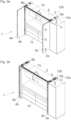
- Fig. 1a shows a perspective view of a piece of furniture 1 with a furniture body 2 and furniture parts 3a, 3b; 4a, 4b that can be moved relative to it in the form of plate-shaped door leaves.
- the furniture parts 3a, 3b and the furniture parts 4a, 4b are each movably mounted by a guide system 5 between a first position in which the furniture parts 3a, 3b; 4a, 4b are aligned essentially coplanar to one another, and a second position in which the furniture parts 3a, 3b; 4a, 4b are aligned essentially parallel to one another.
- the furniture parts 3a, 3b can be inserted into a lateral receiving compartment 8a of the furniture body 2 in a second (parallel) position, while the furniture parts 4a, 4b can be inserted into a further receiving compartment 8b in a parallel position to one another.
- the functionality is explained below using furniture parts 3a and 3b, whereby the same explanations apply to furniture parts 4a, 4b.
- the guide system 5 comprises a first guide rail 7a with a longitudinal direction (L), whereby a guide carriage 6 that can be connected to the second furniture part 3b is mounted so that it can move along the first guide rail 7a.
- Fig. 1b shows the furniture 1, where the furniture parts 3a, 3b starting from the Fig. 1a shown coplanar position into an angular position to one another.
- the first furniture part 3a is mounted via two or more furniture hinges 10 on a carrier 11, which can be inserted into the receiving compartment 8a in a depth direction (Z).
- the carrier 11 is in a transfer position, in which the carrier 11 adjoins the first guide rail 7a in the longitudinal direction (L), so that the guide carriage 6 can be transferred back and forth between the first guide rail 7a and the carrier 11.
- the carrier 11 is releasably locked to the first guide rail 7a, wherein the locking between the first guide rail 7a and the carrier 11 can be released by the guide carriage 6 entering into or onto the carrier 11.
- the support 11 is designed in the form of an elongated column, the length of which corresponds to at least half the height of the furniture parts 3a, 3b.
- the two furniture parts 3a, 3b are connected to one another in an articulated manner about a vertically extending axis via at least one hinge fitting 9.
- the second furniture part 3b is mounted so that it can move along the first guide rail 7a via the guide carriage 6.
- Fig. 2a shows the furniture 1 with the furniture parts 3a and 3b, which are now aligned parallel to each other.
- the carrier 11 was unlocked by the guide carriage 6 entering the first guide rail 7a, so that the carrier 11 (together with the guide carriage 6 and the furniture parts 3a, 3b) can be pushed into the receiving compartment 8a in the depth direction (Z), for example along a second guide rail of the guide system 5 (not shown) running transversely to the longitudinal direction (L).
- Fig. 2b shows the furniture 1 with the furniture parts 3a, 3b, which are now in a fully inserted state in the receiving compartment 8a.
- the furniture parts 3a, 3b are thus guided by the guide system 5 from a first position according to Fig. 1a , in which the furniture parts 3a, 3b are aligned substantially coplanar to each other, and a second position according to Fig. 2b , in which the furniture parts 3a, 3b are aligned essentially parallel to each other and are accommodated within the receiving compartment 8a.
- a Figures 2a, 2b shown kitchen 12 can be completely covered so that the kitchen 12 can be visually separated from the remaining area of a living space.
- the receiving compartment 8a is formed by a side wall 13a and a partition wall 13b spaced parallel to the side wall 13a, wherein the furniture parts 3a, 3b can be inserted in a parallel position to one another between the side wall 13a and the partition wall 13b.
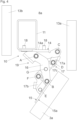
- Fig. 3 shows the carrier 11 arranged between the side wall 13a and the partition wall 13b in a cross section, this representation of the Fig. 2a shown position of the furniture parts 3a, 3b.
- the carrier 11 can be inserted into the receiving compartment 8a in the depth direction (Z).
- the carrier 11 is formed by an elongated hollow profile.
- at least one furniture hinge 10 is provided, which has a first fitting part 14 for fastening to the carrier 11 and a second fitting part 15 for fastening to the furniture part 3a.
- the first fitting part 14 can be fastened either to the carrier 11 shown or alternatively to another furniture part (for example to the side wall 13a or to the partition wall 13b).
- the first fitting part 14 and/or the second fitting part 15 can have at least one fastening point 18, which for example as a hole for screws 21 ( Fig. 7 ) or as a dowel, preferably an expandable one.
- the first fitting part 14 has a flat first contact surface 14a for contact with the support 11 or with a furniture part (for example with the side wall 13a or with the partition wall 13b), while the second fitting part 15 is provided with a flat second contact surface 15a.
- the two fitting parts 14, 15 are movable relative to one another between a first position in which the contact surfaces 14a, 15a are arranged substantially at right angles to one another ( Fig. 3 ), and a second position in which the contact surfaces 14a, 15a are arranged substantially parallel to each other ( Fig. 5 ), movably mounted.
- the furniture hinge 10 has a joint mechanism 19 which connects the first fitting part 14 and the second fitting part 15 to one another in an articulated manner and which has at least five, preferably at least seven, joint axes (A, B, C, D, E, F, G).
- the joint mechanism 19 has at least one support lever 16 which directly connects the first fitting part 14 and the second fitting part 15 to one another.
- the support lever 16 is therefore connected to the first fitting part 14 via a first joint axis (A) and directly to the second fitting part 15 via a second joint axis (B), with the support lever 16 bearing the main load of the furniture hinge 10.
- a movement sequence between the first fitting part 14 and the second fitting part 15 can be controlled by a control mechanism 17 which is separate from the support lever 16.
- the control mechanism 17 has at least three pivotable control levers 17a, 17b, 17c.
- a first control lever 17a is connected to the first fitting part 14 via a third joint axis (C) and to a third control lever 17c via a fourth joint axis (D), the third control lever 17c being pivotably mounted on the support lever 16 about a seventh joint axis (G).
- a second control lever 17b is pivotally connected to the second fitting part 15 via a fifth joint axis (E) and to the third control lever 17c via a sixth joint axis (F).
- all joint axes (A, B, C, D, E, F, G) of the furniture hinge 10 in an assembled state of the furniture hinge 10 on the movable furniture part 3a, preferably in all operating positions of the Furniture hinge 10, are arranged outside a wall thickness of the movable furniture part 3a.
- Fig. 4 shows a further movement of the first fitting part 14 and the second fitting part 15 towards each other, whereby the position of the first furniture part 3a corresponds approximately to the Figure 1b
- the support lever 16 can be clearly seen, which is connected directly to the first fitting part 14 via the first joint axis (A) and directly to the second fitting part 15 via the second joint axis (B).
- the third control lever 17c is connected to the support lever 16 about the seventh joint axis (G), with a first lever end of the third control lever 17c being connected to the first control lever 17a via the fourth joint axis (D) and a second lever end of the third control lever 17c being connected to the second control lever 17b via the sixth joint axis (F).
- the support lever 16 is curved at least in sections along a longitudinal extension of the support lever 16. It can be seen that the at least one support lever 16 is mounted together on the second fitting part 15 via the joint axis (B) and the second control lever 17b is mounted together on the second fitting part 15 via the joint axis (E).
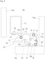
- Fig. 5 shows a further movement of the first fitting part 14 and the second fitting part 15 towards each other, whereby the position of the first furniture part 3a of the Figure 1b corresponds, wherein the furniture parts 3a, 3b are aligned essentially coplanar to one another.
- the control mechanism 17 of the furniture hinge 10 is designed such that the first furniture part 3a covers an end face 20 of the side wall 13a at least in sections, preferably essentially completely. In this way, when the furniture 1 is viewed from the front, there is an overall smooth surface - without the formation of a step or gap visible from the front between the side wall 13a and the movable furniture part 3a.
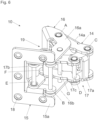
- Fig. 6 shows the furniture hinge 10 in a perspective view.
- the at least one support lever 16 has at least two partial levers 16a, 16b, which are spaced apart from one another along the joint axes (A, B, C, D, E, F, G). This makes it possible to realize a stable construction which is particularly suitable for storing heavy furniture parts 3a.
- At least one of the control levers 17a, 17b, 17c, preferably all control levers 17a, 17b, 17c, is or are arranged at least partially between the partial levers 16a, 16b of the support lever 16, and/or that at least one of the control levers 17a, 17b, 17c, preferably all control levers 17a, 17b, 17c, has or have at least two partial levers which are spaced apart from one another along the joint axes (A, B, C, D, E, F, G).
- Fig. 7 shows the furniture hinge 10 in an exploded view.
- the support lever 16 and/or at least one control lever 17a, 17b, 17c, preferably all control levers 17a, 17b, 17c can have at least two pivot bearings spaced apart from one another along a joint axis (A, B, C, D, E, F, G) for receiving the joint axes (A, B, C, D, E, F, G).
- a joint axis A, B, C, D, E, F, G
- the joint axes (A, B, C, D, E, F, G) are mounted in these pivot bearings so that they can rotate and/or be moved to a limited extent.
- the second fitting part 15 has at least one web 22a, 22b, which projects transversely, preferably substantially at a right angle, from the contact surface 15a of the second fitting part 15 and which is provided for supporting the support lever 16 (in the present case for supporting the two partial levers 16a, 16b of the support lever 16 on the two joint axes (B, E)).
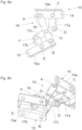
- Fig. 8a shows a top view of a furniture hinge 10 according to a further embodiment.
- This is also a furniture hinge 10 with seven joint axes (A, B, C, D, E, F, G), wherein the support lever 19 of the joint mechanism 19 is directly connected both to the first fitting part 14 by the joint axis (A) and to the second fitting part 15 by the joint axis (B).
- the first fitting part 14 is designed to be attached to the support 11, while the second fitting part 15 is to be fixed to the furniture part 3a.
- This embodiment differs from the previous embodiment by a different position of the joint axes (A, B, C, D, E, F, G) and by a different shape of the support lever 10 and the control levers 17a, 17b, 17c.
- the support lever 10 is essentially straight, while the control lever 17a has an angular shape.
- Fig. 8b shows the embodiment according to Fig. 8a in a perspective view. This embodiment is particularly suitable for moving a single furniture part 3
Landscapes
- Engineering & Computer Science (AREA)
- Mechanical Engineering (AREA)
- Hinges (AREA)
Claims (14)
- Système de guidage (5) pour le guidage d'au moins un élément de meuble (3a) monté mobile par rapport à une paroi latérale (13a) d'un corps de meuble (2), comprenant:- un support (11), lequel dans l'état de montage est monté de manière à pouvoir se déplacer par rapport au corps de meuble (2) dans une direction de profondeur (Z) de la paroi latérale (13a),- au moins une charnière de meuble (10) pour le montage mobile de l'au moins un élément de meuble (3a) par rapport au corps de meuble (2), dans lequel l'au moins une charnière de meuble (10) présente:- un premier élément de ferrure (14) pour la fixation sur le support (11) monté mobile,- un deuxième élément de ferrure (15) pour la fixation sur l'élément de meuble (3a) monté mobile,- dans lequel le premier élément de ferrure (14) et le deuxième élément de ferrure (15) de la charnière de meuble (10) sont montés mobiles l'un par rapport à l'autre entre une première position, dans laquelle l'au moins un élément de meuble (3a) dans l'état de montage est orienté sensiblement parallèlement à la paroi latérale (13a) et est déplaçable conjointement avec le support (11) dans la direction de profondeur (Z) du corps de meuble (2), et une deuxième position, dans laquelle l'au moins un élément de meuble (3a) dans l'état de montage recouvre une face frontale (20) de la paroi latérale (13a) au moins sur certaines parties, de préférence sensiblement entièrement,- un mécanisme d'articulation (19), lequel relie le premier élément de ferrure (14) et le deuxième élément de ferrure (15) l'un à l'autre de manière articulée, dans lequel le mécanisme d'articulation (19) présente au moins cinq, de préférence au moins sept axes d'articulation (A, B, C, D, E, D, G),- dans lequel le mécanisme d'articulation (19) présente au moins un levier de support (16), lequel relie le premier élément de ferrure (14) et le deuxième élément de ferrure (15) l'un à l'autre directement, c'est-à-dire sans interposition d'un autre levier d'articulation,- dans lequel le mécanisme d'articulation (19) présente un mécanisme de commande (17) séparé d'au moins un levier de support (16) pour la commande d'une séquence de mouvement entre le premier élément de ferrure (14) et le deuxième élément de ferrure (15), dans lequel le mécanisme de commande (17) présente au moins trois leviers de commande (17a, 17b, 17c) reliés les uns aux autres de manière articulée,- dans lequel un premier levier de commande (17a) est relié au premier élément de ferrure (14) par l'intermédiaire d'un axe d'articulation (C) et un deuxième levier de commande (17b) au deuxième élément de ferrure (15) par l'intermédiaire d'un axe d'articulation (E) et dans lequel un troisième levier de commande (17c) relie le premier levier de commande (17a) et le deuxième levier de commande (17b) l'un à l'autre.
- Système de guidage (5) selon la revendication 1, caractérisé en ce que l'au moins un levier de support (16) est relié de manière pivotante au premier élément de ferrure (14) par l'intermédiaire d'un premier axe d'articulation (A) et au deuxième élément de ferrure (15) par l'intermédiaire d'un deuxième axe d'articulation (B).
- Système de guidage (5) selon la revendication 1 ou 2, caractérisé en ce que l'au moins un levier de support (16) est réalisé de manière au moins en partie courbée au moins sur certaines parties le long d'une étendue longitudinale du levier de support (16).
- Système de guidage (5) selon l'une quelconque des revendications 1 à 3, caractérisé en ce que l'au moins un levier de support (16) présente au moins deux paliers rotatifs espacés l'un de l'autre le long d'un axe d'articulation (A, B) pour la réception des axes d'articulation (A, B).
- Système de guidage (5) selon l'une quelconque des revendications 1 à 4, caractérisé en ce que le premier élément de ferrure (14) et/ou le deuxième élément de ferrure (15) présente ou présentent au moins un point de fixation (18) pour la fixation à un élément de meuble (3a).
- Système de guidage (5) selon l'une quelconque des revendications 1 à 5, caractérisé en ce que les axes d'articulation (A, B, C, D, E, F, G) dans un état de montage de la charnière de meuble (3) s'étendent sensiblement verticalement.
- Système de guidage (5) selon l'une quelconque des revendications 1 à 6, caractérisé en ce que le troisième levier de commande (17b) est relié de manière pivotante à l'au moins un levier de support (16) par l'intermédiaire d'un axe d'articulation (G).
- Système de guidage (5) selon l'une quelconque des revendications 1 à 7, caractérisé en ce que tous les axes d'articulation (A, B, C, D, E, F, G) de la charnière de meuble (10) dans un état monté de la charnière de meuble (10) sont disposés sur l'élément de meuble (3a) mobile, de préférence dans toutes les positions de fonctionnement de la charnière de meuble (10), à l'extérieur d'une épaisseur de paroi de l'élément de meuble (3a) mobile.
- Système de guidage (5) selon l'une quelconque des revendications 1 à 8, caractérisé en ce que l'au moins un levier de support (16) par l'intermédiaire de l'axe d'articulation (B) et le deuxième levier de commande (17b) par l'intermédiaire de l'axe d'articulation (E) sont montés conjointement sur le deuxième élément de ferrure (15).
- Système de guidage selon l'une quelconque des revendications 1 à 9, caractérisé en ce que l'au moins un levier de support (16) présente au moins deux leviers partiels (16a, 16b), lesquels sont espacés l'un de l'autre le long des axes d'articulation (A, B, C, D, E, F, G), dans lequel de préférence il est prévu qu'au moins un des leviers de commande (17a, 17b, 17c), de préférence tous les leviers de commande (17a, 17b, 17c), soit ou soient disposé(s) au moins en partie entre les leviers partiels (16a, 16b) du levier de support (16), et/ou qu'au moins un des leviers de commande (17a, 17b, 17c), de préférence tous les leviers de commande (17a, 17b, 17c), présente ou présentent au moins deux leviers partiels, lesquels sont espacés l'un de l'autre le long des axes d'articulation (A, B, C, D, E, F, G).
- Meuble (1) avec un corps de meuble (2) et avec au moins un élément de meuble (3a) mobile par rapport au corps de meuble (2), et avec un système de guidage (5) selon l'une quelconque des revendications 1 à 10 pour le mouvement de l'élément de meuble (3a) mobile par rapport au corps de meuble (2).
- Meuble (1) selon la revendication 11, caractérisé en ce que le mécanisme de commande (17) de la charnière de meuble (10) est réalisé de telle sorte qu'au moins un élément de meuble (3a) est monté mobile entre une première position, dans laquelle l'élément de meuble (3a) est orienté sensiblement parallèlement à la paroi latérale (13a) du corps de meuble (2), et une deuxième position, dans laquelle l'élément de meuble (3a) est orienté sensiblement perpendiculairement à la paroi latérale (13a) du corps de meuble (2), de préférence dans lequel l'au moins un élément de meuble (3a) dans la deuxième position, dans laquelle l'élément de meuble (3a) est orienté sensiblement perpendiculairement à la paroi latérale (13a) du corps de meuble (2), recouvre la face frontale (20) de la paroi latérale (13a) au moins sur certaines parties, de préférence sensiblement entièrement.
- Meuble (1) selon la revendication 12, caractérisé en ce que le meuble (1) présente au moins deux éléments de meuble (3a, 3b), lesquels sont reliés l'un à l'autre de manière articulée par au moins une ferrure de charnière (9) et lesquels sont montés mobiles respectivement par rapport au corps de meuble (2) .
- Meuble (1) selon la revendication 13, caractérisé en ce que le premier élément de meuble (3a) et le deuxième élément de meuble (3b) sont montés mobiles entre une première position, dans laquelle le premier élément de meuble (3a) et le deuxième élément de meuble (3b) sont orientés de manière sensiblement coplanaire l'un par rapport à l'autre, et une deuxième position, dans laquelle le premier élément de meuble (3a) et le deuxième élément de meuble (3b) sont orientés sensiblement parallèlement l'un à l'autre.
Applications Claiming Priority (2)
| Application Number | Priority Date | Filing Date | Title |
|---|---|---|---|
| ATA50977/2018A AT521841B1 (de) | 2018-11-13 | 2018-11-13 | Möbelscharnier |
| PCT/AT2019/060367 WO2020097644A1 (fr) | 2018-11-13 | 2019-11-05 | Charnière de meuble |
Publications (2)
| Publication Number | Publication Date |
|---|---|
| EP3880916A1 EP3880916A1 (fr) | 2021-09-22 |
| EP3880916B1 true EP3880916B1 (fr) | 2024-12-25 |
Family
ID=68542539
Family Applications (1)
| Application Number | Title | Priority Date | Filing Date |
|---|---|---|---|
| EP19802033.1A Active EP3880916B1 (fr) | 2018-11-13 | 2019-11-05 | Système de guidage pour le guidage d'au moins une partie de meuble montée de manière mobile |
Country Status (9)
| Country | Link |
|---|---|
| US (1) | US11739577B2 (fr) |
| EP (1) | EP3880916B1 (fr) |
| JP (1) | JP7354244B2 (fr) |
| CN (1) | CN113015835A (fr) |
| AT (1) | AT521841B1 (fr) |
| ES (1) | ES3012959T3 (fr) |
| MY (1) | MY201284A (fr) |
| TW (1) | TWI729558B (fr) |
| WO (1) | WO2020097644A1 (fr) |
Families Citing this family (3)
| Publication number | Priority date | Publication date | Assignee | Title |
|---|---|---|---|---|
| AT524557B1 (de) | 2020-12-17 | 2022-07-15 | Blum Gmbh Julius | Führungssystem zur Führung wenigstens eines Türflügels relativ zu einem Möbelkorpus |
| CA3211342A1 (fr) * | 2021-03-09 | 2022-09-15 | Matthew Brown | Porte pliante pour systeme de paroi mobile |
| AT525246B1 (de) * | 2021-12-21 | 2023-02-15 | Blum Gmbh Julius | Beschlag zur bewegbaren Lagerung eines Schwenkelements |
Citations (2)
| Publication number | Priority date | Publication date | Assignee | Title |
|---|---|---|---|---|
| DE643260C (de) * | 1935-09-20 | 1937-04-02 | Bruno Jacob | Vollstaendig verdeckt liegendes dreiteiliges Scharnier fuer Fahrzeugtueren |
| JP3195311B2 (ja) * | 1999-04-26 | 2001-08-06 | タキゲン製造株式会社 | 7軸型蝶番 |
Family Cites Families (20)
| Publication number | Priority date | Publication date | Assignee | Title |
|---|---|---|---|---|
| US2144977A (en) * | 1935-09-19 | 1939-01-24 | Bruno Jacob | Hinge for curved vehicle doors |
| US2674761A (en) * | 1951-08-03 | 1954-04-13 | Soss Mfg Company | Concealed hinge |
| GB758932A (en) * | 1953-10-01 | 1956-10-10 | British Thomson Houston Co Ltd | Improvements in and relating to hinged doors |
| DE2406439A1 (de) * | 1974-02-11 | 1975-08-21 | Praemeta | Verdecktes scharnier fuer tuerfluegel, insbesondere moebelscharnier |
| DE2361748A1 (de) * | 1973-12-12 | 1975-06-19 | Praemeta | Verdecktes scharnier fuer tuerfluegel, insbesondere moebelscharnier |
| EP0007387B1 (fr) | 1978-07-31 | 1981-10-28 | Hüls Troisdorf Aktiengesellschaft | Procédé de neutralisation d'hydrocarbures chlorés |
| DE3210721A1 (de) * | 1982-03-24 | 1983-10-06 | Kueffner Reinhold Innenausbau | Anlenkbeschlag fuer gebaeude- und moebel-tueren, bzw. -fenster |
| DE19709461C2 (de) * | 1997-03-07 | 2002-08-08 | Gerhard Wittenberg | Führungseinrichtung für eine verschiebbare Wand |
| JP3715958B2 (ja) | 2002-10-18 | 2005-11-16 | 株式会社ムラコシ精工 | 折戸装置 |
| WO2006053364A1 (fr) | 2004-11-22 | 2006-05-26 | Julius Blum Gmbh | Charniere a amortisseur |
| ITMI20061214A1 (it) | 2006-06-23 | 2007-12-24 | Dada S P A | Armadio o mobile similare con sportelli pieghevoli e scorrevoli a scomparsa |
| ITMI20062235A1 (it) | 2006-11-22 | 2008-05-23 | Agostino Ferrari Spa | Assieme di cerniera a quadrilatero articolato con barra stabilizzatrice adattabile per ante a movimento verticale |
| US8007026B2 (en) * | 2009-06-02 | 2011-08-30 | Ford Global Technologies, Llc | Lockout feature for full open hinge |
| EP2978916A1 (fr) * | 2013-03-26 | 2016-02-03 | Arçelik Anonim Sirketi | Mécanisme de charnière de dispositif de refroidissement et dispositif d'installation de câble |
| AU2015202678B2 (en) * | 2014-05-23 | 2019-08-22 | D.G.N. S.R.L. | Snap hinge with damped closing |
| AT517343B1 (de) | 2015-06-29 | 2017-01-15 | Blum Gmbh Julius | Ausstoßvorrichtung für eine Falttür oder Falt-Schiebe-Tür |
| US10676974B2 (en) * | 2016-11-02 | 2020-06-09 | The Braun Corporation | Overtravel hinge |
| AT519513B1 (de) | 2017-01-13 | 2022-09-15 | Blum Gmbh Julius | Anordnung zur Führung einer Schiebetür oder Falt-Schiebetür an einer Möbelwand |
| AT519247B1 (de) * | 2017-01-13 | 2018-05-15 | Blum Gmbh Julius | Führungssystem zur Führung zumindest eines bewegbar gelagerten Türflügels |
| AT519479B1 (de) * | 2017-05-11 | 2018-07-15 | Blum Gmbh Julius | Führungssystem zur Führung eines Türflügels |
-
2018
- 2018-11-13 AT ATA50977/2018A patent/AT521841B1/de active
-
2019
- 2019-11-05 CN CN201980074747.2A patent/CN113015835A/zh active Pending
- 2019-11-05 ES ES19802033T patent/ES3012959T3/es active Active
- 2019-11-05 MY MYPI2021002578A patent/MY201284A/en unknown
- 2019-11-05 JP JP2021525869A patent/JP7354244B2/ja active Active
- 2019-11-05 WO PCT/AT2019/060367 patent/WO2020097644A1/fr not_active Ceased
- 2019-11-05 EP EP19802033.1A patent/EP3880916B1/fr active Active
- 2019-11-07 TW TW108140360A patent/TWI729558B/zh active
-
2021
- 2021-05-12 US US17/318,295 patent/US11739577B2/en active Active
Patent Citations (2)
| Publication number | Priority date | Publication date | Assignee | Title |
|---|---|---|---|---|
| DE643260C (de) * | 1935-09-20 | 1937-04-02 | Bruno Jacob | Vollstaendig verdeckt liegendes dreiteiliges Scharnier fuer Fahrzeugtueren |
| JP3195311B2 (ja) * | 1999-04-26 | 2001-08-06 | タキゲン製造株式会社 | 7軸型蝶番 |
Also Published As
| Publication number | Publication date |
|---|---|
| WO2020097644A1 (fr) | 2020-05-22 |
| JP7354244B2 (ja) | 2023-10-02 |
| MY201284A (en) | 2024-02-15 |
| TW202031990A (zh) | 2020-09-01 |
| AT521841B1 (de) | 2023-02-15 |
| ES3012959T3 (en) | 2025-04-10 |
| US20210262258A1 (en) | 2021-08-26 |
| CN113015835A (zh) | 2021-06-22 |
| JP2022507349A (ja) | 2022-01-18 |
| EP3880916A1 (fr) | 2021-09-22 |
| AT521841A1 (de) | 2020-05-15 |
| US11739577B2 (en) | 2023-08-29 |
| TWI729558B (zh) | 2021-06-01 |
Similar Documents
| Publication | Publication Date | Title |
|---|---|---|
| EP3622154B1 (fr) | Système de guidage pour le guidage d'un battant de porte | |
| EP3880922B1 (fr) | Système de guidage pour le guidage d'un battant de porte monté de manière mobile | |
| EP2916688B1 (fr) | Glissière télescopique de tiroir | |
| EP2527576B1 (fr) | Dispositif de déplacement pour éléments de séparation maintenus de manière rotative et élément de mobilier | |
| AT521139B1 (de) | Führungssystem zur Führung eines bewegbar gelagerten Türflügels | |
| EP3969703B1 (fr) | Système de guidage pour guider au moins un battant de porte | |
| EP3568550A1 (fr) | Système de guidage pour vantail | |
| EP4077850B1 (fr) | Système de guidage permettant de guider un battant de porte monté de manière mobile | |
| EP4180601B1 (fr) | Penture dotée d'un coulisseau de guidage allongé | |
| DE19608496A1 (de) | Drehstab-Türfeststeller für Kraftwagentüren | |
| AT521841B1 (de) | Möbelscharnier | |
| EP4263991B1 (fr) | Système de guidage pour guider au moins un battant de porte par rapport à un corps de meuble | |
| AT16936U1 (de) | Vorrichtung zum Bewegen einer Schiebetür oder Falt-Schiebetür | |
| EP3420167B1 (fr) | Entraînement de bras d'actionnement | |
| EP3064683B1 (fr) | Systeme de chariot pour porte coulissante | |
| EP3880918A1 (fr) | Charnière de meuble | |
| WO2022126167A1 (fr) | Ensemble de guidage d'une partie de meuble mobile | |
| EP3737816B1 (fr) | Charnière de meuble, panneau de meuble et corps de meuble | |
| EP4453358B1 (fr) | Ferrure destinée au montage mobile d'un élément pivotant | |
| EP3775455B1 (fr) | Agencement de ferrure | |
| EP0900904A2 (fr) | Charnière pour couvertures de conteneur | |
| EP3299531B1 (fr) | Dalle de plafond de faux-plafond avec élément de verrouillage activable sans outil | |
| EP2287427B1 (fr) | Charnière à un axe | |
| EP2400094A2 (fr) | Agencement de ferrure | |
| EP4083359A1 (fr) | Dispositif coulissant pour une porte coulissante et meuble |
Legal Events
| Date | Code | Title | Description |
|---|---|---|---|
| STAA | Information on the status of an ep patent application or granted ep patent |
Free format text: STATUS: UNKNOWN |
|
| STAA | Information on the status of an ep patent application or granted ep patent |
Free format text: STATUS: THE INTERNATIONAL PUBLICATION HAS BEEN MADE |
|
| PUAI | Public reference made under article 153(3) epc to a published international application that has entered the european phase |
Free format text: ORIGINAL CODE: 0009012 |
|
| STAA | Information on the status of an ep patent application or granted ep patent |
Free format text: STATUS: REQUEST FOR EXAMINATION WAS MADE |
|
| 17P | Request for examination filed |
Effective date: 20210426 |
|
| AK | Designated contracting states |
Kind code of ref document: A1 Designated state(s): AL AT BE BG CH CY CZ DE DK EE ES FI FR GB GR HR HU IE IS IT LI LT LU LV MC MK MT NL NO PL PT RO RS SE SI SK SM TR |
|
| DAV | Request for validation of the european patent (deleted) | ||
| DAX | Request for extension of the european patent (deleted) | ||
| STAA | Information on the status of an ep patent application or granted ep patent |
Free format text: STATUS: EXAMINATION IS IN PROGRESS |
|
| P01 | Opt-out of the competence of the unified patent court (upc) registered |
Effective date: 20230523 |
|
| 17Q | First examination report despatched |
Effective date: 20230601 |
|
| GRAP | Despatch of communication of intention to grant a patent |
Free format text: ORIGINAL CODE: EPIDOSNIGR1 |
|
| STAA | Information on the status of an ep patent application or granted ep patent |
Free format text: STATUS: GRANT OF PATENT IS INTENDED |
|
| INTG | Intention to grant announced |
Effective date: 20240711 |
|
| GRAS | Grant fee paid |
Free format text: ORIGINAL CODE: EPIDOSNIGR3 |
|
| GRAA | (expected) grant |
Free format text: ORIGINAL CODE: 0009210 |
|
| STAA | Information on the status of an ep patent application or granted ep patent |
Free format text: STATUS: THE PATENT HAS BEEN GRANTED |
|
| AK | Designated contracting states |
Kind code of ref document: B1 Designated state(s): AL AT BE BG CH CY CZ DE DK EE ES FI FR GB GR HR HU IE IS IT LI LT LU LV MC MK MT NL NO PL PT RO RS SE SI SK SM TR |
|
| REG | Reference to a national code |
Ref country code: GB Ref legal event code: FG4D Free format text: NOT ENGLISH |
|
| REG | Reference to a national code |
Ref country code: CH Ref legal event code: EP |
|
| REG | Reference to a national code |
Ref country code: DE Ref legal event code: R096 Ref document number: 502019012705 Country of ref document: DE |
|
| REG | Reference to a national code |
Ref country code: IE Ref legal event code: FG4D Free format text: LANGUAGE OF EP DOCUMENT: GERMAN |
|
| REG | Reference to a national code |
Ref country code: LT Ref legal event code: MG9D Ref country code: ES Ref legal event code: FG2A Ref document number: 3012959 Country of ref document: ES Kind code of ref document: T3 Effective date: 20250410 |
|
| PG25 | Lapsed in a contracting state [announced via postgrant information from national office to epo] |
Ref country code: HR Free format text: LAPSE BECAUSE OF FAILURE TO SUBMIT A TRANSLATION OF THE DESCRIPTION OR TO PAY THE FEE WITHIN THE PRESCRIBED TIME-LIMIT Effective date: 20241225 |
|
| PG25 | Lapsed in a contracting state [announced via postgrant information from national office to epo] |
Ref country code: FI Free format text: LAPSE BECAUSE OF FAILURE TO SUBMIT A TRANSLATION OF THE DESCRIPTION OR TO PAY THE FEE WITHIN THE PRESCRIBED TIME-LIMIT Effective date: 20241225 |
|
| PG25 | Lapsed in a contracting state [announced via postgrant information from national office to epo] |
Ref country code: BG Free format text: LAPSE BECAUSE OF FAILURE TO SUBMIT A TRANSLATION OF THE DESCRIPTION OR TO PAY THE FEE WITHIN THE PRESCRIBED TIME-LIMIT Effective date: 20241225 |
|
| PG25 | Lapsed in a contracting state [announced via postgrant information from national office to epo] |
Ref country code: NO Free format text: LAPSE BECAUSE OF FAILURE TO SUBMIT A TRANSLATION OF THE DESCRIPTION OR TO PAY THE FEE WITHIN THE PRESCRIBED TIME-LIMIT Effective date: 20250325 |
|
| PG25 | Lapsed in a contracting state [announced via postgrant information from national office to epo] |
Ref country code: LV Free format text: LAPSE BECAUSE OF FAILURE TO SUBMIT A TRANSLATION OF THE DESCRIPTION OR TO PAY THE FEE WITHIN THE PRESCRIBED TIME-LIMIT Effective date: 20241225 Ref country code: GR Free format text: LAPSE BECAUSE OF FAILURE TO SUBMIT A TRANSLATION OF THE DESCRIPTION OR TO PAY THE FEE WITHIN THE PRESCRIBED TIME-LIMIT Effective date: 20250326 |
|
| PG25 | Lapsed in a contracting state [announced via postgrant information from national office to epo] |
Ref country code: RS Free format text: LAPSE BECAUSE OF FAILURE TO SUBMIT A TRANSLATION OF THE DESCRIPTION OR TO PAY THE FEE WITHIN THE PRESCRIBED TIME-LIMIT Effective date: 20250325 |
|
| REG | Reference to a national code |
Ref country code: NL Ref legal event code: MP Effective date: 20241225 |
|
| PG25 | Lapsed in a contracting state [announced via postgrant information from national office to epo] |
Ref country code: NL Free format text: LAPSE BECAUSE OF FAILURE TO SUBMIT A TRANSLATION OF THE DESCRIPTION OR TO PAY THE FEE WITHIN THE PRESCRIBED TIME-LIMIT Effective date: 20241225 |
|
| PG25 | Lapsed in a contracting state [announced via postgrant information from national office to epo] |
Ref country code: SM Free format text: LAPSE BECAUSE OF FAILURE TO SUBMIT A TRANSLATION OF THE DESCRIPTION OR TO PAY THE FEE WITHIN THE PRESCRIBED TIME-LIMIT Effective date: 20241225 |
|
| PG25 | Lapsed in a contracting state [announced via postgrant information from national office to epo] |
Ref country code: PL Free format text: LAPSE BECAUSE OF FAILURE TO SUBMIT A TRANSLATION OF THE DESCRIPTION OR TO PAY THE FEE WITHIN THE PRESCRIBED TIME-LIMIT Effective date: 20241225 |
|
| PG25 | Lapsed in a contracting state [announced via postgrant information from national office to epo] |
Ref country code: IS Free format text: LAPSE BECAUSE OF FAILURE TO SUBMIT A TRANSLATION OF THE DESCRIPTION OR TO PAY THE FEE WITHIN THE PRESCRIBED TIME-LIMIT Effective date: 20250425 |
|
| PG25 | Lapsed in a contracting state [announced via postgrant information from national office to epo] |
Ref country code: PT Free format text: LAPSE BECAUSE OF FAILURE TO SUBMIT A TRANSLATION OF THE DESCRIPTION OR TO PAY THE FEE WITHIN THE PRESCRIBED TIME-LIMIT Effective date: 20250428 |
|
| PG25 | Lapsed in a contracting state [announced via postgrant information from national office to epo] |
Ref country code: EE Free format text: LAPSE BECAUSE OF FAILURE TO SUBMIT A TRANSLATION OF THE DESCRIPTION OR TO PAY THE FEE WITHIN THE PRESCRIBED TIME-LIMIT Effective date: 20241225 |
|
| PG25 | Lapsed in a contracting state [announced via postgrant information from national office to epo] |
Ref country code: RO Free format text: LAPSE BECAUSE OF FAILURE TO SUBMIT A TRANSLATION OF THE DESCRIPTION OR TO PAY THE FEE WITHIN THE PRESCRIBED TIME-LIMIT Effective date: 20241225 |
|
| PG25 | Lapsed in a contracting state [announced via postgrant information from national office to epo] |
Ref country code: SK Free format text: LAPSE BECAUSE OF FAILURE TO SUBMIT A TRANSLATION OF THE DESCRIPTION OR TO PAY THE FEE WITHIN THE PRESCRIBED TIME-LIMIT Effective date: 20241225 |
|
| PG25 | Lapsed in a contracting state [announced via postgrant information from national office to epo] |
Ref country code: CZ Free format text: LAPSE BECAUSE OF FAILURE TO SUBMIT A TRANSLATION OF THE DESCRIPTION OR TO PAY THE FEE WITHIN THE PRESCRIBED TIME-LIMIT Effective date: 20241225 |
|
| PG25 | Lapsed in a contracting state [announced via postgrant information from national office to epo] |
Ref country code: SE Free format text: LAPSE BECAUSE OF FAILURE TO SUBMIT A TRANSLATION OF THE DESCRIPTION OR TO PAY THE FEE WITHIN THE PRESCRIBED TIME-LIMIT Effective date: 20241225 |
|
| REG | Reference to a national code |
Ref country code: DE Ref legal event code: R097 Ref document number: 502019012705 Country of ref document: DE |
|
| PG25 | Lapsed in a contracting state [announced via postgrant information from national office to epo] |
Ref country code: DK Free format text: LAPSE BECAUSE OF FAILURE TO SUBMIT A TRANSLATION OF THE DESCRIPTION OR TO PAY THE FEE WITHIN THE PRESCRIBED TIME-LIMIT Effective date: 20241225 |
|
| PLBE | No opposition filed within time limit |
Free format text: ORIGINAL CODE: 0009261 |
|
| STAA | Information on the status of an ep patent application or granted ep patent |
Free format text: STATUS: NO OPPOSITION FILED WITHIN TIME LIMIT |
|
| REG | Reference to a national code |
Ref country code: CH Ref legal event code: L10 Free format text: ST27 STATUS EVENT CODE: U-0-0-L10-L00 (AS PROVIDED BY THE NATIONAL OFFICE) Effective date: 20251105 |
|
| REG | Reference to a national code |
Ref country code: CH Ref legal event code: U11 Free format text: ST27 STATUS EVENT CODE: U-0-0-U10-U11 (AS PROVIDED BY THE NATIONAL OFFICE) Effective date: 20251201 |
|
| 26N | No opposition filed |
Effective date: 20250926 |
|
| PGFP | Annual fee paid to national office [announced via postgrant information from national office to epo] |
Ref country code: DE Payment date: 20251126 Year of fee payment: 7 |
|
| PGFP | Annual fee paid to national office [announced via postgrant information from national office to epo] |
Ref country code: AT Payment date: 20251126 Year of fee payment: 7 |
|
| PGFP | Annual fee paid to national office [announced via postgrant information from national office to epo] |
Ref country code: IT Payment date: 20251121 Year of fee payment: 7 |
|
| PGFP | Annual fee paid to national office [announced via postgrant information from national office to epo] |
Ref country code: CH Payment date: 20251201 Year of fee payment: 7 |
|
| PGFP | Annual fee paid to national office [announced via postgrant information from national office to epo] |
Ref country code: ES Payment date: 20251209 Year of fee payment: 7 |