EP3880978B1 - Befestigungselement für dünnes folienmaterial - Google Patents
Befestigungselement für dünnes folienmaterial Download PDFInfo
- Publication number
- EP3880978B1 EP3880978B1 EP19884547.1A EP19884547A EP3880978B1 EP 3880978 B1 EP3880978 B1 EP 3880978B1 EP 19884547 A EP19884547 A EP 19884547A EP 3880978 B1 EP3880978 B1 EP 3880978B1
- Authority
- EP
- European Patent Office
- Prior art keywords
- panel
- fastener
- conical portion
- shank
- collar
- Prior art date
- Legal status (The legal status is an assumption and is not a legal conclusion. Google has not performed a legal analysis and makes no representation as to the accuracy of the status listed.)
- Active
Links
Images

Classifications
-
- F—MECHANICAL ENGINEERING; LIGHTING; HEATING; WEAPONS; BLASTING
- F16—ENGINEERING ELEMENTS AND UNITS; GENERAL MEASURES FOR PRODUCING AND MAINTAINING EFFECTIVE FUNCTIONING OF MACHINES OR INSTALLATIONS; THERMAL INSULATION IN GENERAL
- F16B—DEVICES FOR FASTENING OR SECURING CONSTRUCTIONAL ELEMENTS OR MACHINE PARTS TOGETHER, e.g. NAILS, BOLTS, CIRCLIPS, CLAMPS, CLIPS OR WEDGES; JOINTS OR JOINTING
- F16B19/00—Bolts without screw-thread; Pins, including deformable elements; Rivets
- F16B19/04—Rivets; Spigots or the like fastened by riveting
- F16B19/05—Bolts fastening by swaged-on collars
-
- F—MECHANICAL ENGINEERING; LIGHTING; HEATING; WEAPONS; BLASTING
- F16—ENGINEERING ELEMENTS AND UNITS; GENERAL MEASURES FOR PRODUCING AND MAINTAINING EFFECTIVE FUNCTIONING OF MACHINES OR INSTALLATIONS; THERMAL INSULATION IN GENERAL
- F16B—DEVICES FOR FASTENING OR SECURING CONSTRUCTIONAL ELEMENTS OR MACHINE PARTS TOGETHER, e.g. NAILS, BOLTS, CIRCLIPS, CLAMPS, CLIPS OR WEDGES; JOINTS OR JOINTING
- F16B37/00—Nuts or like thread-engaging members
- F16B37/04—Devices for fastening nuts to surfaces, e.g. sheets, plates
- F16B37/06—Devices for fastening nuts to surfaces, e.g. sheets, plates by means of welding or riveting
- F16B37/062—Devices for fastening nuts to surfaces, e.g. sheets, plates by means of welding or riveting by means of riveting
- F16B37/065—Devices for fastening nuts to surfaces, e.g. sheets, plates by means of welding or riveting by means of riveting by deforming the material of the nut
-
- F—MECHANICAL ENGINEERING; LIGHTING; HEATING; WEAPONS; BLASTING
- F16—ENGINEERING ELEMENTS AND UNITS; GENERAL MEASURES FOR PRODUCING AND MAINTAINING EFFECTIVE FUNCTIONING OF MACHINES OR INSTALLATIONS; THERMAL INSULATION IN GENERAL
- F16B—DEVICES FOR FASTENING OR SECURING CONSTRUCTIONAL ELEMENTS OR MACHINE PARTS TOGETHER, e.g. NAILS, BOLTS, CIRCLIPS, CLAMPS, CLIPS OR WEDGES; JOINTS OR JOINTING
- F16B39/00—Locking of screws, bolts or nuts
- F16B39/02—Locking of screws, bolts or nuts in which the locking takes place after screwing down
Definitions
- the present invention is in the field of clinch type fasteners or rivets. More specifically, it relates to fasteners of the type which deform to capture the host material to which they are attached.
- Micro fasteners have been getting smaller and are usually applied in very thin sheets of metal. This helps minimize the space needed in an assembly. Fasteners that work well in these applications have been loose fasteners that can be removed and clinching and rivet fasteners which give a permanent connection.
- Clinching fasteners will usually offer a high push-out and torque-out performance but they require a displacer, an undercut, and a shank on the fastener. Clinch fasteners come in different forms but they all share the fact that the push-out resistance features and the torque-out resistance features are independent of each other.
- the push-out forces are produced by the displacer on the fastener engaging with the panel causing the material to flow into the undercut on the fastener.
- the torque-out forces are created by knurls that engage with the mating panel which prevent the fastener from rotating in place. Additional sheet thickness is required so the material can flow into the undercut.
- rivet nuts have been used because they do not distort the base material but offer a high torque-out and push-out performance.
- the nut is placed in the hole and the installation tool engages by the threads on the inside. When the tool pulls on the threads, it causes the thinner material to bulge to the side. This usually results in material from the fastener being prominent on both sides of the panel. This may be unfavorable because it adds thickness when all pieces are assembled.
- Some rivet nuts can be manufactured with a flat head that allows one side to be flush, but it needs greater panel thickness to add that feature.
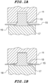
- Illustrations 1A and 1B of Figure 1 depict a prior art fastener which utilizes a deformable band of material 13 employed to capture a sheet of material 15 between the band and the head 17 of the fastener when pressed between punch 11 and anvil 19.
- the assembly utilizes a flat panel with a simple round hole. It is deficient in that it exhibits poor torque-out performance and the fastener head is not flush with the backside of the panel.
- Another prior art fastener is known from US 3 014 563 A .
- the applicant has devised a fastener with a shank having a collar which is a deformable band of material which when properly engaged with its mating panel offers good torque-out and push-out resistance.
- the purpose of the present fastener is to provide a fastener which can be used with a sheet of 0.1mm minimum thickness while providing effective push-out and torque-out resistances. While clinch fasteners of the prior art have a shank, an undercut, and a displacer to provide push-out and torque-out resistances the present fastener utilizes structures on the mating panel in conjunction with an undercut as well as a deformed shank collar to produce enhanced attachment forces.
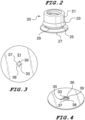
- the mating panel has a round mounting hole with cross-cut openings or slots cut into the panel in the area of the mounting hole.
- the panel is also stamped into a conical portion around the mounting hole.
- a fastener as set out in claims 1 and 2, comprising a shank having a base at a bottom most end thereof, said base being the largest diameter of the fastener.
- a deformable collar on the shank of greater diameter than the shank includes an undercut in the shank having a inner wall of lesser diameter than the shank. The undercut is located immediately below the collar.
- the shank may be threaded internally or externally.
- the fastener can be used in a panel assembly, as set out in claims 3 to 7, 9 and 10 where the fastener is affixed to a panel having a top side and a back side, and wherein the panel has a raised conical portion extending upwardly from the panel top side which defines a recess in the panel back side.
- a mounting hole is centered at the apex of the conical portion and defines a top of the conical portion.
- the deformable collar is pressed against the conical portion in the direction of the base thereby rigidly clamping the conical portion between the collar and the base. Due to the pressing, portions of the deformable collar flow into and remain within the radial slots.
- Undercut 25 includes an inner wall 29 at its junction with the shank 21.
- the slots are added in part to allow the panel tabs 37 to flex as they are pressed around the deformable collar 23 of the fastener 20.
- a cross cut pattern is used to create four tabs 37 that move into place in the undercut 25 during a preliminary snap-in assembly of the fastener 20 to the panel 31.
- the conical stamping allows the panel to bend in a desirable way that will permit the fastener to easily snap into place.
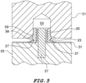
- the fastener 20 and panel 31 are placed into a press punch 51 having receiving cavity 53.
- the gripping ends of the panel tabs 38 abut the shank within the undercut.
- the punch 51 and the fastener 20 are then aligned on pin 57 of anvil 55 to ensure even distribution of the material of the deformable collar 23.
- the collar 23 as it is deformed will press easily against the panel tabs 37 which occupy the undercut 25.
- the collar material flows into the panel cross-cut slots creating a resistance to rotation as seen in Figure 6A .
- the punch 51 has a rounded edge 59 to displace the material as it presses down to guide the material into the panel slots.
- the radius 59 is sized so that it will not shear off the deformable collar. The installation process stops when the punch contacts the top of the panel 31 supported by flat anvil 55.
- Figures 6A and 6B of Figure 6 are sectional views taken from a front view and a side view, respectively.
- a front sectional view taken through the opposing slots on the sides of the fastener shows collar material 23 having flowed into the slots and touching the fastener base 27.
- the sectional side view shows the panel tabs 37 captured between the fastener base 27 and the collar 23, which has spread along the top of the panel forming a flange 62.
- This construction necessarily benefits from deforming the fastener's material because the panel is already very thin and hard, making traditional clinching impossible.
- the embodiment of Figure 6 has an optional internally threaded bore 61.
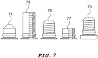
- Figure 7 depicts the operative features of the invention adapted to different types of fasteners to provide a solution to other applications that require installation into very thin, hard panels. From left to right these illustrations depict the following: a pin 71, a standoff with an internally threaded bore 73, an externally threaded stud 75, a nut 77 and a threaded stud with an enlarged head 79.
- the force of attachment is enhanced compared to prior art clinch nuts of the same thread diameter in two ways.
- torque-out resistance is greatly increased by the portions of the deformable collar which is embedded in the slots between the conical portion tabs.
- the top edges of the tabs wedge into undercut area against the undercut inner wall in direct reaction to pull-out forces which increases pull-out resistance.
Landscapes
- Engineering & Computer Science (AREA)
- General Engineering & Computer Science (AREA)
- Mechanical Engineering (AREA)
- Insertion Pins And Rivets (AREA)
- Connection Of Plates (AREA)
Claims (11)
- Befestigungselement (20), umfassend:einen Schaft (21) mit einer Basis (27) am untersten Ende davon, wobei die Basis (27) den größten Durchmesser des Befestigungselements (20) darstellt; gekennzeichnet durcheinen verformbaren Kragen (23) am Schaft (21) mit größerem Durchmesser als der Schaft (21), wobei der Kragen (23) in der Form eines nach unten divergierenden, sich verjüngenden Bandes ist; undeine Hinterschneidung (25) im Schaft (21), die eine Innenwand (29) mit geringerem Durchmesser als der Schaft (21) aufweist und sich unmittelbar unterhalb des Kragens (23) befindet.
- Befestigungselement (20) nach Anspruch 1, wobei der Schaft (21) eine axiale Gewindebohrung (61) aufweist.
- Baugruppe eines Befestigungselements (20) an einer Platte (31), umfassend:
das Befestigungselement (20) nach Anspruch 1, das an einer Platte (31) befestigt ist, wobei die Platte (31) eine Oberseite und eine Rückseite aufweist:wobei die Platte (31) einen erhabenen konischen Abschnitt (35) aufweist, der sich von der Plattenoberseite nach oben erstreckt und eine Aussparung in der Plattenrückseite eingrenzt;ein Montageloch (33), das an der Spitze des konischen Abschnitts (35) mittig angeordnet ist, wobei das Loch (33) eine Oberkante des konischen Abschnitts (35) eingrenzt;wobei sich der Befestigungsschaft (21) nach oben durch das Montageloch (33) erstreckt und der konische Abschnitt (35) der Platte (31) zwischen dem Kragen (23) und der Basis (27) gefangen ist;wobei die Platte mehrere radiale Schlitze (39) im konischen Abschnitt (35) aufweist und Abschnitte des verformbaren Kragens (23) innerhalb der Schlitze liegen; undwobei Elemente des konischen Abschnitts (35) innerhalb der Hinterschneidung (25) liegen und der Schaft (21) eine axiale Gewindebohrung (61) aufweist. - Baugruppe nach Anspruch 3, wobei die Basis (27) vollständig innerhalb der rückseitigen Aussparung liegt.
- Baugruppe nach Anspruch 3, wobei die Oberkante (38) des konischen Abschnitts (35) an der Innenwand (29) der Hinterschneidung (25) anliegt.
- Baugruppe nach Anspruch 3, wobei die Platte (31) von einer gleichmäßigen Dicke ist.
- Baugruppe nach Anspruch 3, wobei die Platte (31) aus elastischem Material besteht, wodurch das Befestigungselement (20) durch Einrasten an der Platte (31) befestigt wird.
- Verfahren zum Befestigen eines Befestigungselements an einer Platte, gekennzeichnet durch starres Befestigen des Befestigungselements (20) an der Platte (31) in der Baugruppe nach Anspruch 3 mit einem Schritt des Drückens des verformbaren Kragens (23) gegen den konischen Abschnitt (35) in Richtung der Basis (27), wobei dadurch der konische Abschnitt (35) zwischen dem Kragen (23) und der Basis (27) festgeklemmt wird.
- Baugruppe nach Anspruch 6, wobei vier radiale Schlitze (39) in einem Kreuzschnittmuster vorhanden sind, die sich jeweils vom Montageloch (33) bis zu einem Umfang des konischen Abschnitts (35) erstrecken.
- Baugruppe nach Anspruch 9, wobei der konische Abschnitt (35) aus vier Laschen (37) besteht, die sich jeweils vom Montageloch (33) bis zum Umfang (36) des konischen Abschnitts (35) erstrecken.
- Verfahren nach Anspruch 8, wobei nach dem Schritt des Pressens Abschnitte des verformbaren Kragens (23) innerhalb der radialen Schlitze (39) liegen.
Applications Claiming Priority (2)
| Application Number | Priority Date | Filing Date | Title |
|---|---|---|---|
| US201862760508P | 2018-11-13 | 2018-11-13 | |
| PCT/US2019/060522 WO2020102026A1 (en) | 2018-11-13 | 2019-11-08 | Fastener for thin sheet material |
Publications (4)
| Publication Number | Publication Date |
|---|---|
| EP3880978A1 EP3880978A1 (de) | 2021-09-22 |
| EP3880978A4 EP3880978A4 (de) | 2022-08-03 |
| EP3880978B1 true EP3880978B1 (de) | 2024-06-12 |
| EP3880978C0 EP3880978C0 (de) | 2024-06-12 |
Family
ID=70550079
Family Applications (1)
| Application Number | Title | Priority Date | Filing Date |
|---|---|---|---|
| EP19884547.1A Active EP3880978B1 (de) | 2018-11-13 | 2019-11-08 | Befestigungselement für dünnes folienmaterial |
Country Status (11)
| Country | Link |
|---|---|
| US (1) | US11428256B2 (de) |
| EP (1) | EP3880978B1 (de) |
| JP (1) | JP7558162B2 (de) |
| CN (1) | CN113302407B (de) |
| CA (1) | CA3119542C (de) |
| HU (1) | HUE067615T2 (de) |
| MX (1) | MX2021005589A (de) |
| PL (1) | PL3880978T3 (de) |
| SG (1) | SG11202104897WA (de) |
| TW (1) | TWI843765B (de) |
| WO (1) | WO2020102026A1 (de) |
Families Citing this family (2)
| Publication number | Priority date | Publication date | Assignee | Title |
|---|---|---|---|---|
| USD941134S1 (en) * | 2020-03-11 | 2022-01-18 | Heiko Schmidt | Rivet nut |
| USD941133S1 (en) * | 2020-03-11 | 2022-01-18 | Heiko Schmidt | Rivet nut |
Family Cites Families (33)
| Publication number | Priority date | Publication date | Assignee | Title |
|---|---|---|---|---|
| US1249948A (en) * | 1914-06-25 | 1917-12-11 | Hydraulic Pressed Steel Company | Process of uniting articles to sheet-metal supports. |
| US3014563A (en) * | 1957-06-12 | 1961-12-26 | Gen Motors Corp | Anchor assembly |
| NL111314C (de) * | 1958-06-24 | |||
| GB1050351A (de) * | 1959-05-06 | |||
| US3770037A (en) * | 1971-12-15 | 1973-11-06 | Penn Eng Mfg Corp | Self-clinching stud with a modified head |
| JPS5193069U (de) * | 1975-01-24 | 1976-07-26 | ||
| US4033222A (en) * | 1975-08-21 | 1977-07-05 | Monogram Industries, Inc. | Multiple sleeve blind fastener |
| GB2051284A (en) * | 1979-06-06 | 1981-01-14 | Tr Fastenings Ltd | Riveted Bush |
| JPS5770512U (de) * | 1980-10-16 | 1982-04-28 | ||
| US5006025A (en) * | 1989-12-13 | 1991-04-09 | Avibank Mfg., Inc. | Self-locking nut |
| HU214609B (hu) * | 1992-07-07 | 1998-06-29 | Richard Bergner Gmbh. Und Co. | Eljárás kinyomás és elforgatás ellen biztosító összekötő elem besajtolóelemnek lemezbe való besajtolása által történő előállítására és besajtoló elem az eljárás végrehajtására |
| US6125524A (en) * | 1994-03-25 | 2000-10-03 | Multifastener Corporation | Rivetable element, assembly, method of assembly and riveting die |
| JPH1047328A (ja) | 1996-07-29 | 1998-02-17 | Topy Fastener Kogyo Kk | プッシュナット |
| DE20012097U1 (de) * | 2000-07-12 | 2000-12-28 | Textron Verbindungstechnik GmbH & Co. oHG, 56567 Neuwied | Verdreh- und auspreßsicher in ein Blech einpreßbares Befestigungselement |
| US7124492B2 (en) * | 2001-07-19 | 2006-10-24 | Whitesell International Corporation | Fastener, method of attaching a fastener to a panel and fastener and panel assembly |
| US6592311B2 (en) | 2001-07-19 | 2003-07-15 | Fabristeel Products, Inc. | Double-ended self-attaching stud |
| US6761520B1 (en) | 2003-05-09 | 2004-07-13 | Pem Management, Inc. | Clinch-type blind nut |
| US7207762B2 (en) * | 2003-12-23 | 2007-04-24 | Federal-Mogul World Wide, Inc. | Push-on screw-off attachment device |
| US20060204348A1 (en) * | 2005-03-08 | 2006-09-14 | Shuart David M | Self-attaching fastener and fastener and panel assembly |
| DE102007034987A1 (de) * | 2007-07-26 | 2009-01-29 | Profil Verbindungstechnik Gmbh & Co. Kg | Einpresselement zum Einpressen in ein nicht gelochtes oder gelochtes Bauteil sowie Verfahren zur Herstellung des Einpresselements |
| CN101990607B (zh) * | 2008-04-09 | 2013-01-16 | Pem管理股份有限公司 | 塑料-金属混合螺母柱 |
| CN201202720Y (zh) * | 2008-05-12 | 2009-03-04 | 钛积创新科技股份有限公司 | 螺柱定位装置 |
| CN201636181U (zh) * | 2009-12-14 | 2010-11-17 | 贵州航天精工制造有限公司 | 一种防转动的自锁铆螺母 |
| CN103573778A (zh) * | 2012-07-25 | 2014-02-12 | 广州汽车集团股份有限公司 | 一种新型紧固件 |
| US8973248B2 (en) | 2012-10-05 | 2015-03-10 | Toyota Motor Engineering & Manufacturing North America, Inc. | Connection assembly for connecting metallic and plastic components and method of connecting plastic and metallic components |
| US10006478B2 (en) * | 2015-01-22 | 2018-06-26 | Arconic Inc. | Blind fasteners |
| SG11201803296UA (en) * | 2015-10-22 | 2018-05-30 | Penn Eng & Mfg Corp | Thin-sheet clinch fastener |
| CN205453995U (zh) * | 2016-01-04 | 2016-08-10 | 中兴通讯股份有限公司 | 一种薄板铆接结构和插箱设备 |
| CN206129842U (zh) * | 2016-09-30 | 2017-04-26 | 无锡安欣达科技有限公司 | 一种折叠式铆接螺母 |
| CN106976044B (zh) * | 2017-03-02 | 2023-04-25 | 杭州联伟科技有限公司 | 铆接工具附件及铆接工具 |
| US10337543B2 (en) * | 2017-04-04 | 2019-07-02 | Multimaterial-Welding Ag | Securing a second object to a first object |
| CN108468700A (zh) * | 2018-06-27 | 2018-08-31 | 浙江洪扬汽车零部件有限公司 | 一种片型压花螺母 |
| CN108644210A (zh) * | 2018-06-27 | 2018-10-12 | 浙江洪扬汽车零部件有限公司 | 一种防拉伤拉铆螺母 |
-
2019
- 2019-11-08 MX MX2021005589A patent/MX2021005589A/es unknown
- 2019-11-08 CN CN201980088912.XA patent/CN113302407B/zh active Active
- 2019-11-08 HU HUE19884547A patent/HUE067615T2/hu unknown
- 2019-11-08 SG SG11202104897WA patent/SG11202104897WA/en unknown
- 2019-11-08 CA CA3119542A patent/CA3119542C/en active Active
- 2019-11-08 JP JP2021525207A patent/JP7558162B2/ja active Active
- 2019-11-08 PL PL19884547.1T patent/PL3880978T3/pl unknown
- 2019-11-08 US US16/678,509 patent/US11428256B2/en active Active
- 2019-11-08 WO PCT/US2019/060522 patent/WO2020102026A1/en not_active Ceased
- 2019-11-08 EP EP19884547.1A patent/EP3880978B1/de active Active
- 2019-11-13 TW TW108141143A patent/TWI843765B/zh active
Also Published As
| Publication number | Publication date |
|---|---|
| TW202028622A (zh) | 2020-08-01 |
| CN113302407B (zh) | 2023-04-11 |
| JP7558162B2 (ja) | 2024-09-30 |
| CN113302407A (zh) | 2021-08-24 |
| HUE067615T2 (hu) | 2024-11-28 |
| SG11202104897WA (en) | 2021-06-29 |
| WO2020102026A1 (en) | 2020-05-22 |
| MX2021005589A (es) | 2021-08-05 |
| TWI843765B (zh) | 2024-06-01 |
| US20200149575A1 (en) | 2020-05-14 |
| CA3119542C (en) | 2025-05-27 |
| PL3880978T3 (pl) | 2024-08-19 |
| CA3119542A1 (en) | 2020-05-22 |
| EP3880978A4 (de) | 2022-08-03 |
| EP3880978C0 (de) | 2024-06-12 |
| US11428256B2 (en) | 2022-08-30 |
| EP3880978A1 (de) | 2021-09-22 |
| JP2022507054A (ja) | 2022-01-18 |
Similar Documents
| Publication | Publication Date | Title |
|---|---|---|
| EP2516870B1 (de) | Mutter mit ansatzaufweitung | |
| US3276499A (en) | Flush-driven self-piercing and clinching nut and method of securing to a member | |
| JP3479144B2 (ja) | リベット | |
| US7306418B2 (en) | Deforming member and captive fastener retaining method | |
| EP1248911B1 (de) | Gummibefestiger schnellen zugangs für platten | |
| EP2490838A1 (de) | Klammerstifthalterung | |
| JPH03210931A (ja) | 自己ピアシング・リベッティング・ファスナのパネルへの取付け法及び自己ピアシング・リベッティング・ファスナのパネルへの取付け用ダイ部材 | |
| US11428256B2 (en) | Fastener for thin sheet material | |
| US20170009793A1 (en) | Clamping Clinch Fastener | |
| EP3329135B1 (de) | Kegelkopfeinpressverschluss | |
| TWI742301B (zh) | 具有壓縮套之插入式緊固件、包含此緊固件的組合件以及將插件安裝至板中之方法 | |
| EP1856419A2 (de) | Selbsthaftender festiger und anordnung aus dem festiger und einer tafel | |
| CN110685987A (zh) | 带有螺旋滚花柄的铆紧式紧固件 | |
| TW201719030A (zh) | 保持平裝物件的緊固件 | |
| US2630935A (en) | Eyelet joint and method of forming same | |
| US8230574B2 (en) | Method for inserting connecting elements in metal sheets and connection between a metal sheet and a connecting element | |
| CN115247670B (zh) | 自冲压功能元件、部件组件以及制造部件组件的方法 | |
| CN222668648U (zh) | 一种压铆螺母及连接系统 | |
| KR102916220B1 (ko) | 다목적 파일럿이 있는 셀프-클린칭 및 셀프-피어싱 건축 요소 | |
| US20210341009A1 (en) | Functional Element | |
| US4530619A (en) | Self-retaining nut and method of applying to a panel | |
| CN115076199A (zh) | 功能元件 | |
| JP2002168225A (ja) | プッシュナット |
Legal Events
| Date | Code | Title | Description |
|---|---|---|---|
| STAA | Information on the status of an ep patent application or granted ep patent |
Free format text: STATUS: THE INTERNATIONAL PUBLICATION HAS BEEN MADE |
|
| PUAI | Public reference made under article 153(3) epc to a published international application that has entered the european phase |
Free format text: ORIGINAL CODE: 0009012 |
|
| STAA | Information on the status of an ep patent application or granted ep patent |
Free format text: STATUS: REQUEST FOR EXAMINATION WAS MADE |
|
| 17P | Request for examination filed |
Effective date: 20210609 |
|
| AK | Designated contracting states |
Kind code of ref document: A1 Designated state(s): AL AT BE BG CH CY CZ DE DK EE ES FI FR GB GR HR HU IE IS IT LI LT LU LV MC MK MT NL NO PL PT RO RS SE SI SK SM TR |
|
| DAV | Request for validation of the european patent (deleted) | ||
| DAX | Request for extension of the european patent (deleted) | ||
| A4 | Supplementary search report drawn up and despatched |
Effective date: 20220701 |
|
| RIC1 | Information provided on ipc code assigned before grant |
Ipc: F16B 37/04 20060101ALI20220627BHEP Ipc: F16B 37/06 20060101AFI20220627BHEP |
|
| GRAP | Despatch of communication of intention to grant a patent |
Free format text: ORIGINAL CODE: EPIDOSNIGR1 |
|
| STAA | Information on the status of an ep patent application or granted ep patent |
Free format text: STATUS: GRANT OF PATENT IS INTENDED |
|
| INTG | Intention to grant announced |
Effective date: 20240207 |
|
| GRAS | Grant fee paid |
Free format text: ORIGINAL CODE: EPIDOSNIGR3 |
|
| GRAA | (expected) grant |
Free format text: ORIGINAL CODE: 0009210 |
|
| STAA | Information on the status of an ep patent application or granted ep patent |
Free format text: STATUS: THE PATENT HAS BEEN GRANTED |
|
| AK | Designated contracting states |
Kind code of ref document: B1 Designated state(s): AL AT BE BG CH CY CZ DE DK EE ES FI FR GB GR HR HU IE IS IT LI LT LU LV MC MK MT NL NO PL PT RO RS SE SI SK SM TR |
|
| REG | Reference to a national code |
Ref country code: GB Ref legal event code: FG4D |
|
| REG | Reference to a national code |
Ref country code: CH Ref legal event code: EP |
|
| REG | Reference to a national code |
Ref country code: IE Ref legal event code: FG4D |
|
| REG | Reference to a national code |
Ref country code: DE Ref legal event code: R096 Ref document number: 602019053741 Country of ref document: DE |
|
| U01 | Request for unitary effect filed |
Effective date: 20240613 |
|
| U07 | Unitary effect registered |
Designated state(s): AT BE BG DE DK EE FI FR IT LT LU LV MT NL PT SE SI Effective date: 20240624 |
|
| PG25 | Lapsed in a contracting state [announced via postgrant information from national office to epo] |
Ref country code: HR Free format text: LAPSE BECAUSE OF FAILURE TO SUBMIT A TRANSLATION OF THE DESCRIPTION OR TO PAY THE FEE WITHIN THE PRESCRIBED TIME-LIMIT Effective date: 20240612 |
|
| PG25 | Lapsed in a contracting state [announced via postgrant information from national office to epo] |
Ref country code: GR Free format text: LAPSE BECAUSE OF FAILURE TO SUBMIT A TRANSLATION OF THE DESCRIPTION OR TO PAY THE FEE WITHIN THE PRESCRIBED TIME-LIMIT Effective date: 20240913 |
|
| PG25 | Lapsed in a contracting state [announced via postgrant information from national office to epo] |
Ref country code: ES Free format text: LAPSE BECAUSE OF FAILURE TO SUBMIT A TRANSLATION OF THE DESCRIPTION OR TO PAY THE FEE WITHIN THE PRESCRIBED TIME-LIMIT Effective date: 20240612 |
|
| PG25 | Lapsed in a contracting state [announced via postgrant information from national office to epo] |
Ref country code: NO Free format text: LAPSE BECAUSE OF FAILURE TO SUBMIT A TRANSLATION OF THE DESCRIPTION OR TO PAY THE FEE WITHIN THE PRESCRIBED TIME-LIMIT Effective date: 20240912 Ref country code: HR Free format text: LAPSE BECAUSE OF FAILURE TO SUBMIT A TRANSLATION OF THE DESCRIPTION OR TO PAY THE FEE WITHIN THE PRESCRIBED TIME-LIMIT Effective date: 20240612 Ref country code: GR Free format text: LAPSE BECAUSE OF FAILURE TO SUBMIT A TRANSLATION OF THE DESCRIPTION OR TO PAY THE FEE WITHIN THE PRESCRIBED TIME-LIMIT Effective date: 20240913 Ref country code: ES Free format text: LAPSE BECAUSE OF FAILURE TO SUBMIT A TRANSLATION OF THE DESCRIPTION OR TO PAY THE FEE WITHIN THE PRESCRIBED TIME-LIMIT Effective date: 20240612 Ref country code: RS Free format text: LAPSE BECAUSE OF FAILURE TO SUBMIT A TRANSLATION OF THE DESCRIPTION OR TO PAY THE FEE WITHIN THE PRESCRIBED TIME-LIMIT Effective date: 20240912 |
|
| U20 | Renewal fee for the european patent with unitary effect paid |
Year of fee payment: 6 Effective date: 20241007 |
|
| REG | Reference to a national code |
Ref country code: HU Ref legal event code: AG4A Ref document number: E067615 Country of ref document: HU |
|
| PG25 | Lapsed in a contracting state [announced via postgrant information from national office to epo] |
Ref country code: IS Free format text: LAPSE BECAUSE OF FAILURE TO SUBMIT A TRANSLATION OF THE DESCRIPTION OR TO PAY THE FEE WITHIN THE PRESCRIBED TIME-LIMIT Effective date: 20241012 |
|
| PG25 | Lapsed in a contracting state [announced via postgrant information from national office to epo] |
Ref country code: RO Free format text: LAPSE BECAUSE OF FAILURE TO SUBMIT A TRANSLATION OF THE DESCRIPTION OR TO PAY THE FEE WITHIN THE PRESCRIBED TIME-LIMIT Effective date: 20240612 Ref country code: SK Free format text: LAPSE BECAUSE OF FAILURE TO SUBMIT A TRANSLATION OF THE DESCRIPTION OR TO PAY THE FEE WITHIN THE PRESCRIBED TIME-LIMIT Effective date: 20240612 |
|
| PG25 | Lapsed in a contracting state [announced via postgrant information from national office to epo] |
Ref country code: SM Free format text: LAPSE BECAUSE OF FAILURE TO SUBMIT A TRANSLATION OF THE DESCRIPTION OR TO PAY THE FEE WITHIN THE PRESCRIBED TIME-LIMIT Effective date: 20240612 |
|
| PG25 | Lapsed in a contracting state [announced via postgrant information from national office to epo] |
Ref country code: SM Free format text: LAPSE BECAUSE OF FAILURE TO SUBMIT A TRANSLATION OF THE DESCRIPTION OR TO PAY THE FEE WITHIN THE PRESCRIBED TIME-LIMIT Effective date: 20240612 Ref country code: SK Free format text: LAPSE BECAUSE OF FAILURE TO SUBMIT A TRANSLATION OF THE DESCRIPTION OR TO PAY THE FEE WITHIN THE PRESCRIBED TIME-LIMIT Effective date: 20240612 Ref country code: RO Free format text: LAPSE BECAUSE OF FAILURE TO SUBMIT A TRANSLATION OF THE DESCRIPTION OR TO PAY THE FEE WITHIN THE PRESCRIBED TIME-LIMIT Effective date: 20240612 Ref country code: IS Free format text: LAPSE BECAUSE OF FAILURE TO SUBMIT A TRANSLATION OF THE DESCRIPTION OR TO PAY THE FEE WITHIN THE PRESCRIBED TIME-LIMIT Effective date: 20241012 |
|
| PLBE | No opposition filed within time limit |
Free format text: ORIGINAL CODE: 0009261 |
|
| STAA | Information on the status of an ep patent application or granted ep patent |
Free format text: STATUS: NO OPPOSITION FILED WITHIN TIME LIMIT |
|
| 26N | No opposition filed |
Effective date: 20250313 |
|
| REG | Reference to a national code |
Ref country code: CH Ref legal event code: PL |
|
| PG25 | Lapsed in a contracting state [announced via postgrant information from national office to epo] |
Ref country code: MC Free format text: LAPSE BECAUSE OF FAILURE TO SUBMIT A TRANSLATION OF THE DESCRIPTION OR TO PAY THE FEE WITHIN THE PRESCRIBED TIME-LIMIT Effective date: 20240612 |
|
| REG | Reference to a national code |
Ref country code: CH Ref legal event code: PL |
|
| PG25 | Lapsed in a contracting state [announced via postgrant information from national office to epo] |
Ref country code: CH Free format text: LAPSE BECAUSE OF NON-PAYMENT OF DUE FEES Effective date: 20241130 |
|
| PGFP | Annual fee paid to national office [announced via postgrant information from national office to epo] |
Ref country code: PL Payment date: 20250901 Year of fee payment: 7 |
|
| PGFP | Annual fee paid to national office [announced via postgrant information from national office to epo] |
Ref country code: GB Payment date: 20250918 Year of fee payment: 7 |
|
| PG25 | Lapsed in a contracting state [announced via postgrant information from national office to epo] |
Ref country code: IE Free format text: LAPSE BECAUSE OF NON-PAYMENT OF DUE FEES Effective date: 20241108 |
|
| U20 | Renewal fee for the european patent with unitary effect paid |
Year of fee payment: 7 Effective date: 20251008 |
|
| PGFP | Annual fee paid to national office [announced via postgrant information from national office to epo] |
Ref country code: HU Payment date: 20251013 Year of fee payment: 7 |
|
| PGFP | Annual fee paid to national office [announced via postgrant information from national office to epo] |
Ref country code: CZ Payment date: 20251021 Year of fee payment: 7 |
|
| PG25 | Lapsed in a contracting state [announced via postgrant information from national office to epo] |
Ref country code: CY Free format text: LAPSE BECAUSE OF FAILURE TO SUBMIT A TRANSLATION OF THE DESCRIPTION OR TO PAY THE FEE WITHIN THE PRESCRIBED TIME-LIMIT; INVALID AB INITIO Effective date: 20191108 |