EP3882048B1 - Passage tournant de roue de véhicule, module de roue de véhicule, machine de travail automobile et procédé de fonctionnement d'un passage tournant de roue de véhicule - Google Patents
Passage tournant de roue de véhicule, module de roue de véhicule, machine de travail automobile et procédé de fonctionnement d'un passage tournant de roue de véhicule Download PDFInfo
- Publication number
- EP3882048B1 EP3882048B1 EP20164579.3A EP20164579A EP3882048B1 EP 3882048 B1 EP3882048 B1 EP 3882048B1 EP 20164579 A EP20164579 A EP 20164579A EP 3882048 B1 EP3882048 B1 EP 3882048B1
- Authority
- EP
- European Patent Office
- Prior art keywords
- sealing
- vehicle wheel
- pressure
- rotary feedthrough
- control
- Prior art date
- Legal status (The legal status is an assumption and is not a legal conclusion. Google has not performed a legal analysis and makes no representation as to the accuracy of the status listed.)
- Active
Links
Images





Classifications
-
- B—PERFORMING OPERATIONS; TRANSPORTING
- B60—VEHICLES IN GENERAL
- B60C—VEHICLE TYRES; TYRE INFLATION; TYRE CHANGING; CONNECTING VALVES TO INFLATABLE ELASTIC BODIES IN GENERAL; DEVICES OR ARRANGEMENTS RELATED TO TYRES
- B60C23/00—Devices for measuring, signalling, controlling, or distributing tyre pressure or temperature, specially adapted for mounting on vehicles; Arrangement of tyre inflating devices on vehicles, e.g. of pumps or of tanks; Tyre cooling arrangements
- B60C23/02—Signalling devices actuated by tyre pressure
- B60C23/04—Signalling devices actuated by tyre pressure mounted on the wheel or tyre
- B60C23/0491—Constructional details of means for attaching the control device
- B60C23/0498—Constructional details of means for attaching the control device for rim attachments
-
- B—PERFORMING OPERATIONS; TRANSPORTING
- B60—VEHICLES IN GENERAL
- B60C—VEHICLE TYRES; TYRE INFLATION; TYRE CHANGING; CONNECTING VALVES TO INFLATABLE ELASTIC BODIES IN GENERAL; DEVICES OR ARRANGEMENTS RELATED TO TYRES
- B60C23/00—Devices for measuring, signalling, controlling, or distributing tyre pressure or temperature, specially adapted for mounting on vehicles; Arrangement of tyre inflating devices on vehicles, e.g. of pumps or of tanks; Tyre cooling arrangements
- B60C23/001—Devices for manually or automatically controlling or distributing tyre pressure whilst the vehicle is moving
- B60C23/003—Devices for manually or automatically controlling or distributing tyre pressure whilst the vehicle is moving comprising rotational joints between vehicle-mounted pressure sources and the tyres
- B60C23/00345—Details of the rotational joints
-
- B—PERFORMING OPERATIONS; TRANSPORTING
- B60—VEHICLES IN GENERAL
- B60C—VEHICLE TYRES; TYRE INFLATION; TYRE CHANGING; CONNECTING VALVES TO INFLATABLE ELASTIC BODIES IN GENERAL; DEVICES OR ARRANGEMENTS RELATED TO TYRES
- B60C23/00—Devices for measuring, signalling, controlling, or distributing tyre pressure or temperature, specially adapted for mounting on vehicles; Arrangement of tyre inflating devices on vehicles, e.g. of pumps or of tanks; Tyre cooling arrangements
- B60C23/001—Devices for manually or automatically controlling or distributing tyre pressure whilst the vehicle is moving
- B60C23/003—Devices for manually or automatically controlling or distributing tyre pressure whilst the vehicle is moving comprising rotational joints between vehicle-mounted pressure sources and the tyres
- B60C23/00345—Details of the rotational joints
- B60C23/00347—Details of the rotational joints comprising two or more feedthrough
-
- B—PERFORMING OPERATIONS; TRANSPORTING
- B60—VEHICLES IN GENERAL
- B60C—VEHICLE TYRES; TYRE INFLATION; TYRE CHANGING; CONNECTING VALVES TO INFLATABLE ELASTIC BODIES IN GENERAL; DEVICES OR ARRANGEMENTS RELATED TO TYRES
- B60C23/00—Devices for measuring, signalling, controlling, or distributing tyre pressure or temperature, specially adapted for mounting on vehicles; Arrangement of tyre inflating devices on vehicles, e.g. of pumps or of tanks; Tyre cooling arrangements
- B60C23/001—Devices for manually or automatically controlling or distributing tyre pressure whilst the vehicle is moving
- B60C23/003—Devices for manually or automatically controlling or distributing tyre pressure whilst the vehicle is moving comprising rotational joints between vehicle-mounted pressure sources and the tyres
- B60C23/00363—Details of sealings
-
- B—PERFORMING OPERATIONS; TRANSPORTING
- B60—VEHICLES IN GENERAL
- B60C—VEHICLE TYRES; TYRE INFLATION; TYRE CHANGING; CONNECTING VALVES TO INFLATABLE ELASTIC BODIES IN GENERAL; DEVICES OR ARRANGEMENTS RELATED TO TYRES
- B60C23/00—Devices for measuring, signalling, controlling, or distributing tyre pressure or temperature, specially adapted for mounting on vehicles; Arrangement of tyre inflating devices on vehicles, e.g. of pumps or of tanks; Tyre cooling arrangements
- B60C23/001—Devices for manually or automatically controlling or distributing tyre pressure whilst the vehicle is moving
- B60C23/003—Devices for manually or automatically controlling or distributing tyre pressure whilst the vehicle is moving comprising rotational joints between vehicle-mounted pressure sources and the tyres
- B60C23/00372—Devices for manually or automatically controlling or distributing tyre pressure whilst the vehicle is moving comprising rotational joints between vehicle-mounted pressure sources and the tyres characterised by fluid diagrams
-
- B—PERFORMING OPERATIONS; TRANSPORTING
- B60—VEHICLES IN GENERAL
- B60C—VEHICLE TYRES; TYRE INFLATION; TYRE CHANGING; CONNECTING VALVES TO INFLATABLE ELASTIC BODIES IN GENERAL; DEVICES OR ARRANGEMENTS RELATED TO TYRES
- B60C2200/00—Tyres specially adapted for particular applications
- B60C2200/08—Tyres specially adapted for particular applications for agricultural vehicles
Definitions
- the invention relates to a vehicle wheel rotary leadthrough, which is used in particular in a self-propelled working machine, which can be a tractor, a harvesting vehicle or the like.
- At least one pneumatic signal in particular a pneumatic supply pressure and/or a pneumatic control pressure, is transmitted between two parts rotated relative to one another by means of the vehicle wheel rotary feedthrough.
- These parts are, for example, a non-rotating vehicle wheel carrier and a rotating vehicle wheel, while a control pressure to be transmitted can be a control pressure for a tire pressure control valve held on the vehicle wheel (for example a ventilation valve for the tire of the vehicle wheel).
- the vehicle wheel swivel has a first swivel part, which can be designed as a stator and can be attached or supported on the vehicle wheel carrier, and a second swivel part, which can also be referred to as a rotor and which is connected to the vehicle wheel relative to the vehicle wheel carrier or the stator is twisted.
- the two rotary leadthrough parts are rotatably supported in relation to one another via a bearing.
- the invention relates to a vehicle wheel assembly with such a vehicle wheel rotary feedthrough, a self-propelled work machine with at least one such vehicle wheel assembly and a method for operating such a vehicle wheel rotary feedthrough.
- the pamphlet DE 10 2018 101 411 A1 discloses a non-generic rotary union, which is formed by a wheel bearing of the vehicle wheel, which supports the wheel load, and which serves to conduct a supply pressure to a tire.
- the wheel bearing has an outer ring with an outlet bore opening into the tire of the vehicle wheel and an inner ring with an inlet bore that can be connected to a compressed air source in order to fill the tire.
- a sealing unit is non-rotatably connected to the stationary inner ring.
- the sealing unit has a seal holder which has an inlet channel.
- the supply pressure can pass through the inlet bore of the inner ring into the inlet channel of the seal retainer, with an O-ring sealing between the seal retainer and the inner ring.
- the inlet channel opens into a pressure chamber.
- the pressure chamber is ring-shaped and open in the direction of the outer ring.
- the pressure chamber is closed on the side facing the outer ring by a retaining ring, which carries a wear-resistant, non-elastic support ring and an elastic sealing ring next to one another in the axial direction of the rotary feedthrough.
- the pressure chamber is pressurized, the retaining ring with the support ring and the sealing ring are pressed against the outer ring.
- a first seal is thus provided between the outer ring and the inner ring.
- a second seal is provided by a corresponding further sealing unit.
- a transition cross section is formed, which is sealed off on both sides in the axial direction by the seals by the sealing units.
- Cross bores in the seal holders connect the respective pressure chamber with the intermediate space and thus with the transition area. If the two inlet bores of the inner ring assigned to the sealing units are subjected to the supply pressure, this results in fluid being sealed by the sealing units from the inlet bore of the inner ring to the inlet channel of the seal holder into the pressure chamber and from there via the transverse bore, the space between the seal holders and the transition area can reach the exit bore of the outer ring and thus the tire.
- the contact pressure of the sealing rings and the support rings depends on the size of the supply pressure that is present at the inlet bore of the inner ring.
- the transverse bore emanating from the pressure chamber can be designed as a throttle, so that there is a dynamic pressure in the pressure chamber. Due to the dimensioning of the throttle, the dynamic pressure and thus also the contact pressure of the support ring and the Sealing ring are specified constructively. If the support ring and the sealing ring are worn, the wear is automatically adjusted by moving the retaining ring further outwards according to the extent of the wear as a result of the applied pressure. This movement is caused by an elastic expansion of the retaining ring as a result of the pressure in the pressure chamber. The support ring does not guarantee complete sealing.
- the invention relates to a wheel load-free vehicle wheel rotary joint.
- This is understood to mean a vehicle wheel rotary joint which (deviating from the prior art mentioned at the outset) DE 10 2018 101 411 A1 ) is not formed with the rolling bearings, via which the wheel load of the vehicle wheel is supported. Rather, the wheel-load-free vehicle wheel rotary feedthrough serves only or primarily to connect and connect pneumatic lines and to transmit a pneumatic control pressure and/or supply pressure between the rotary feedthrough parts that are moved relative to one another.
- the vehicle wheel swivel according to the invention has two swivel parts, each of which has a channel.
- the rotary union parts are designed, for example, as an outer ring and inner ring, which are supported directly via a bearing rotatably against each other, it being possible for the inner ring and the outer ring to specify the outer geometry of the vehicle wheel rotary union.
- the first rotary feedthrough part can be designed as a stator, to which in particular lines from the vehicle wheel carrier are connected, while the second rotary feedthrough part can be attached directly or indirectly to the vehicle wheel, in particular a rim (e.g. in the area of the rim base or a rim body or rim flange). can.
- the vehicle wheel rotary leadthrough according to the invention has a transition area that is formed between the two rotary leadthrough parts.
- the transition area connects (preferably independent of the relative angle of rotation of the rotary union parts) the first Channel of the first swivel part with the second channel of the second swivel part.
- the transition area is sealed using sealing units that provide a (complete, extensive or partial) sealing effect.
- sealing units are not used which bring about the sealing effect solely by means of prestressing. Rather, the vehicle wheel swivel has a sealing effect control chamber.
- the sealing effect control chamber can, for example, be formed directly and in one piece by a rotary feedthrough part, in particular a stator formed as an inner ring.
- a seal control channel opens into the sealing effect control chamber.
- a seal control pressure can be applied to the sealing effect control chamber via the seal control channel.
- the sealing unit closes the sealing effect control chamber in the manner of a displaceable piston, wherein several such pistons of several sealing effect control chambers can be arranged distributed in the circumferential direction or the sealing effect control chamber is continuous in the circumferential direction and the sealing unit forms a kind of annular piston.
- the displacement direction of the piston is oriented in the direction of a normal to the surface of the sealing surface with which the sealing unit interacts, or at an acute angle to the normal to the surface.
- the sealing effect control chamber is closed except for the connection with the seal control channel (and as a result of the piston-like sealing by the sealing unit), so that the pressure conditions in the sealing effect control chamber change as a result of the pressure being applied to the seal control channel with the seal control pressure can be.
- a small volume flow from the seal control channel can also enter the sealing effect control chamber or exit again in the opposite direction.
- the sealing effect control chamber is designed as a kind of “dead chamber”.
- the sealing control pressure in the sealing effect control chamber acts on the sealing unit in the radial direction, which means that the sealing unit has a degree of freedom oriented in the radial direction in the manner of a displaceable piston. This creates a sealing force that also acts in the radial direction.
- the sealing unit is then pressed against a cylindrical sealing surface of a rotary leadthrough part, in particular of the rotor, with the sealing force.
- the sealing unit There are many possibilities for designing the sealing unit. It is possible, for example, for the sealing unit to have a piston-like guide body on which at least one sealing element is held, which then comes into operative connection with the associated sealing surface. It is possible that (basically according to the embodiment DE 10 2018 101 411 A1 ) Several sealing elements of the sealing unit are arranged side by side in the axial direction. In this case, the sealing elements can fulfill the same or different functions. If several sealing elements are arranged axially next to one another in this way, they can form a gradual and strengthening seal. It is also possible that one sealing element has greater elasticity in order to provide the actual sealing function, while the other sealing element can have less elasticity or no elasticity and can be designed as a type of wear ring.
- the sealing unit has a first sealing element and a second sealing element.
- These sealing elements are each specifically used for sealing against an associated rotary feedthrough part:
- the first sealing element is used for sealing on the cylindrical sealing surface of a rotary feedthrough part, in particular the rotor. This sealing element is thus pressed against the cylindrical sealing surface in the radial direction.
- a second sealing element seals against the sealing action control chamber formed in the other rotary union part (particularly the stator).
- the second sealing element can ensure a sealing effect of the "piston" in the guide recess of the rotary leadthrough part (in particular the stator), so that this sealing element must ensure a piston-like displacement relative to the rotary leadthrough part on the one hand and a seal transverse to the direction of movement of this sealing element, i.e. transverse to the Degree of freedom of the "piston" must ensure.
- a specific design of the two sealing elements for the assigned functions can take place. For this proposal, the first sealing element and the second sealing element are pressed against one another in the radial direction to ensure sealing when the sealing action control chamber is acted upon by the sealing control pressure.
- the first sealing element can form a first sealing surface on the side facing the cylindrical sealing surface, which abuts the sealing surface, while the first sealing element forms a second sealing surface on the opposite side, on which the second sealing element comes to rest.
- the second sealing element can have a corresponding sealing surface for contact with the first sealing element, as well as at least one further additional sealing surface in the region in which the “piston” is sealed.
- the sealing force generated by the sealing control pressure in the sealing effect control chamber is used to press the second sealing element against the first sealing element in order to bring about a sealing effect between them and to press the first sealing element against the cylindrical sealing surface in order to also achieve a sealing effect here bring about.
- the inner surface of the sliding ring is adapted to the contact with the second sealing element, so that the inner surface can also have a straight half-longitudinal section or can have any curved shape or can have a concave shape.
- the second sealing element can be designed as a flexible and/or elastic sealing ring.
- the sealing ring is preferably produced in an injection molding process or by means of compression molding.
- the sealing ring can be made of an elastic plastic, caoutchouc, perfluorocaoutchouc (FFKM or FFPM), polyethylene (PE) or polytetrafluoroethylene (PTFE), to name just a few examples that do not limit the invention.
- the sealing ring can have any cross-section, for example an O-ring (including the embodiments that are standardized in ISO 3601), an O-ring, a zero ring, a quadring or an X-ring, to give some examples that do not limit the invention to name.
- an inherently rigid slide ring is used as the first sealing element, it must nevertheless be elastically expanded radially depending on the pressure applied with the seal control pressure and it must be possible for the diameter to automatically and elastically decrease when the seal control pressure is reduced. If the inherently rigid slide ring is closed in the circumferential direction, the radial expansion may require large acting forces, which must be brought about by the seal control pressure.
- the configuration of the sliding ring with an inherent rigidity can be used so that when the sealing control pressure is applied, an elastic deformation of the sliding ring takes place, for example an expansion of the same.
- the sealing unit can be brought into contact with the sealing surface, with which the sealing effect can be actively produced. It is also possible that an existing sealing effect is actively reinforced as a result of the widening of the slide ring. If the seal control pressure is then reduced or eliminated, the contact pressure of the sealing unit on the sealing surface should be reduced or the sealing unit should even be moved completely away from the sealing surface so that there is no longer any frictional contact between the sealing unit and the sealing surface.
- This restoring movement which is associated with a reduction in the diameter of the seal ring, can be brought about as a result of the elasticity of the inherently rigid seal ring: If the expanding force acting on the seal ring from the seal control pressure is eliminated, the elasticity of the inherently rigid seal ring creates a restoring force available, which leads to the reduction of the diameter and the consequent reduction of the sealing effect or the complete elimination of the contact between the sliding ring and the sealing surface.
- the inherently rigid slip ring is provided with a slot that allows for easy diameter variation as a result of seal control pressure.
- the sections of the seal ring are subjected to bending in such a way that the curvature of the seal ring and thus the diameter of the seal ring change. With the change in diameter, the slit of the sliding ring can then open or close further.
- the slot can be sealed by an additional sealing element between the end faces delimiting the slot.
- This additional sealing element can, for example, be elastomeric material injected into the slot, or another sealing element is arranged before and/or after the slot in the axial direction.
- the reduction in the sealing effect in the region of the slot is reduced to an acceptable level by the slot not being formed in a straight line.
- the slot it is possible for the slot to be curved, reciprocating, meandering, labyrinthine or stepped.
- the throttling effect can be predetermined, with which the impairment of the sealing effect in the area of the slot can then also be structurally influenced.
- a certain flow through the slot i.e. a limited impairment of the sealing effect
- a certain flow through the contact surface between the inherently rigid slide ring and the sealing surface can be generated in a targeted manner, with this flow then also serving for this purpose can, away from the inherently rigid sealing ring, to flow through existing gaps between the two rotary leadthrough parts, with which these can be cleaned of particles and/or the entry of particles can be avoided.
- the rigidity of the sealing unit and in particular the sliding ring is dimensioned such that the radius of the sealing unit or the sliding ring can be increased elastically with an increase in the sealing control pressure acting in the sealing effect control chamber.
- the sealing unit or the sliding ring is pressed against the sealing surface with an increasing contact pressure, which means that the sealing effect and the sealing force can be increased in a targeted manner.
- the radius of the Sealing unit or the sliding ring can be reduced elastically with a reduction in the sealing control pressure acting in the sealing effect control chamber. In this way, the sealing effect and the sealing force between the sealing unit or the sliding ring and the sealing surface can be reduced.
- the sealing effect control chamber and the transition area are pneumatically connected to one another.
- a seal control channel leading to the sealing action control chamber and the channel leading to the transition area can be connected via a branch to the same channel or connection of the rotary union part.
- the same pressure can be present in the sealing effect control chamber and the transition area.
- different pressures act as a result of a throttling effect and the like despite the connection to the same connection or the same channel in the sealing effect control chamber on the one hand and the transition area on the other.
- the previously explained pneumatic connection of the sealing effect control chamber and the transition area can ensure in a simple manner that a seal control pressure is only generated in the sealing effect control chamber and thus also a generation or increase in the contact pressure of the sealing unit on the sealing surface (and thus a Friction and wear occur when the transition area is also pneumatically loaded.This automatically creates the sealing effect if this is necessary, since a working medium is also to be transferred via the transition area.
- the sealing control chamber on the one hand and the transition area on the other hand are pneumatically separated from one another in the rotary feedthrough part. It is possible that the sealing effect control chamber is connected to a seal control connection via separate pneumatic channels, while the transition area is connected to another connection of the same rotary leadthrough part (in particular a supply input connection or a control input connection) via channels.
- This configuration makes it possible for the seal control pressure on the one hand and the pressure in the transition area on the other hand to be predetermined independently of one another. It is thus also possible to specify the level of the seal control pressure separately, with which the required sealing effect can then be ensured in order to transfer the pressure in the transition area without excessive leaks.
- the vehicle wheel rotary feedthrough has permanent lubrication of the bearing, via which the rotary feedthrough parts are mounted directly against one another. If it is necessary for the bearing to be lubricated at regular intervals, the vehicle wheel rotary union can have a lubricant connection for one proposal of the invention. This lubricant connection is then connected to the bearing, via which the rotary leadthrough parts are mounted such that they can be rotated in relation to one another. In this case, the bearing can also be connected to the sealing units via an intermediate space between the rotary leadthrough parts. In this case, it must be avoided that lubricant reaches the first channel, the transition area and/or the second channel, ie the branch of the working medium, via the sealing units.
- the sealing effect control chamber and the transition area are pneumatically separated, the channels and the transition area are not pressurized and only the sealing effect control chamber is acted upon by the seal control pressure.
- the level of the seal control pressure can also be selected specifically in such a way that a transfer of lubricant is reliably ruled out.
- a further solution to the problem on which the invention is based is a vehicle wheel assembly.
- the vehicle wheel has a tire.
- the vehicle wheel assembly according to the invention also has a tire inflation device, which is intended to ensure that the tire has a predetermined pressure. It is entirely possible that different pressures can also be set in the tire by means of the tire inflation device. For example, when driving the vehicle on the road, a higher pressure can be set in the tire than when driving the vehicle on farmland.
- the tire inflation device used within the scope of the invention has a supply line for a first variant. The supply line emanates from the vehicle wheel carrier and is connected to a supply input connection of the rotary leadthrough part designed as a stator.
- the supply line provides a supply pressure via which the tire can be ventilated, ie filled up or the pressure increased.
- the supply pressure can be provided permanently or as a function of the position of a supply valve, which can be held, for example, on the vehicle wheel carrier.
- the tire inflation device has a control line which is connected to a control input connection of the vehicle wheel swivel.
- the control line also comes from the vehicle wheel carrier. Aeration, locking and/or venting of the tire can be controlled via the control line, with the control pressure in the control line preferably being used to actuate a tire pressure control valve (in particular a ventilation valve) which is arranged downstream of the vehicle wheel rotary union and connected to the Vehicle wheel rotates.
- a tire pressure control valve in particular a ventilation valve
- the tire inflation device preferably has both a supply line and a control line, in which case the control pressure in the control line can also be used to control whether the pressure in the supply line is fed to the tire, the supply line is shut off and/or the tire is deflated he follows.
- the tire inflation device has a vehicle wheel rotary leadthrough, as has been described above.
- the supply pressure and/or the control pressure can then be transmitted via the vehicle wheel rotary union by connecting the supply line or the control line to the first channel, the transition area and the second channel.
- the vehicle wheel is held on the vehicle wheel carrier via a wheel bearing.
- the vehicle wheel rotary feedthrough can then be connected in parallel to the power flow from the vehicle wheel via the wheel bearing to the vehicle wheel carrier, with the vehicle wheel rotary feedthrough being spaced apart and embodied separately from the wheel bearing.
- the second rotary feedthrough part is attached to the vehicle wheel so that it rotates with the vehicle wheel and is designed as a rotor.
- the first rotary feedthrough part is connected to the vehicle wheel carrier via the connected lines and a torque arm, with the result that this is designed as a stator.
- the rotary feedthrough is subjected to minimal forces, but provides the required degree of rotary freedom and the pneumatic transmission.
- the torque support the force for impeding the rotation of the first rotary leadthrough part can be absorbed in such a way that this force does not stress the connected lines.
- a further solution to the problem on which the invention is based is a self-propelled working machine in which a vehicle wheel assembly of the type explained above is used finds. It is possible here for a vehicle wheel assembly of the type explained above to be used on several or all of the vehicle wheels of the self-propelled working machine.
- the self-propelled work machine is designed as an agricultural work machine, tractor, harvester and the like.
- a further solution to the problem on which the invention is based is a method for operating a vehicle wheel rotary union, which is in particular a vehicle wheel rotary union of the type explained above.
- Such a process includes the following process steps: First, a control pressure is applied to a control input connection, in particular to the rotary leadthrough part designed as a stator. Alternatively, a supply pressure can be applied to a supply input connection of the rotary leadthrough part designed as a stator.
- a sealing action control chamber is also loaded with a sealing control pressure.
- the seal control pressure can correspond to the control pressure at the control port or the supply pressure at the supply port.
- the seal control pressure it is also possible for the seal control pressure to be provided separately via a further seal control connection. In this way, a sealing force is then generated, by means of which a sealing effect of at least one sealing unit is brought about or an already existing sealing effect is increased.
- the sealing control pressure in the sealing effect control chamber is reduced in a further method step. This results in a reduction in the sealing force and thus a reduction in the sealing effect of at least one sealing unit.
- the sealing effect can thus be reduced or completely eliminated if no supply pressure or control pressure is to be transmitted by means of the vehicle wheel rotary leadthrough in the area of the transmission channel. As a result, the friction and the wear on the sealing unit of the vehicle wheel rotary leadthrough can be reduced.
- a lubricant connection is simultaneously subjected to a lubricant for a bearing of the vehicle wheel rotary leadthrough and a seal control connection is subjected to a seal control pressure.
- This simultaneous application can prevent the lubricant from spilling over into the transition area when lubricating the bearing via the lubricant connection.
- the seal control pressure can also be chosen to be higher during such a lubrication of the bearing than is the case if no lubrication takes place, but a supply pressure or a control pressure is to be transmitted via the vehicle wheel rotary union.
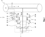
- vehicle wheel 2 has a pressure sensor 4 that detects the pressure in tire 3 .
- the measurement signal of the pressure sensor 4 is preferably transmitted wirelessly to a control unit, not shown here.
- the tire pressure control valve 5 has a pneumatic tire pressure control port 6, a tire pressure vent port 7 and tire pressure supply port 8.
- the tire pressure supply port 8 is connected via a tire pressure supply line 9 to a supply output port 10 of a vehicle wheel rotary union 11.
- the tire pressure control connection 6 is connected to a control output connection 13 of the vehicle wheel rotary union 11 via a tire pressure control line 12 .
- a check valve 14 is arranged, which a flow from the Allows supply output port 10 of the vehicle wheel swivel 11 in the direction of the tire pressure supply port 8, but blocks a reverse flow.
- the vehicle wheel rotary feedthrough 11 has a first rotary feedthrough part 15 which is designed as a stator 16 . Opposite the first rotary leadthrough part 15 , a second rotary leadthrough part 18 designed as a rotor 17 is rotatably mounted by means of a bearing 19 . The supply output port 10 and the control output port 13 are provided on the second rotary union part 18 . In contrast, the first rotary feedthrough part 15 has a supply inlet port 20 and a control inlet port 21.
- the vehicle wheel rotary feedthrough 11 enables the supply pressure at the supply inlet port 20 to the supply outlet port 10 and the control pressure to be transmitted in a completely or largely sealed manner Control input connection 21 to the control output connection 13 despite the rotary relative movement between the rotary leadthrough parts 15, 18.
- the pressure at the supply input port 20 (and thus at the tire pressure supply port 8 of the tire pressure control valve 5) is specified via a supply valve 22.
- the control pressure is specified at the control input port 21 (and thus at the control port 6) in a corresponding manner of the tire pressure control valve 5) via a control valve 23.
- the supply valve 22 and the control valve 23 are designed as electrically controlled or electro-pneumatically pilot-controlled 3/2-way valves, each of which has a venting position in which a supply pressure or a control pressure is generated, and a venting position in which the supply Input port 20 or the control input port 21 is vented, have.
- the supply valve 22 and the control valve 23 are actuated via a control unit, which is preferably the control unit to which the measurement signal of the pressure sensor 4 is also transmitted.
- the operation of the tire inflation device 1 according to 1 is preferably as follows: If the tire 3 is to be inflated or the pressure in the tire 3 is to be increased, the supply valve 22 is controlled to the ventilation position, while the control valve 23 remains in the ventilation position without electrical loading as a result of the action of the spring.
- the supply pressure controlled by the supply valve 22 is transmitted to the tire pressure supply connection 8 of the tire pressure control valve 5 via the vehicle wheel rotary leadthrough 11 and via the check valve 14 which opens in this direction. Without the control pressure present in the tire pressure control line 12 , the tire pressure control valve 5 is in the ventilation position as a result of its spring, so that the compressed air can reach the tire 3 via the tire pressure control valve 5 .
- the supply valve 22 is switched to the ventilation position, while the control valve 23 assumes or maintains the ventilation position 23 . Since the tire pressure control line 12 is not pressurized, the tire pressure control valve 5 assumes or remains in the ventilation position. The consequence of this is that the pressure in the tire 3 is present at the outlet of the check valve 14, while the inlet of the check valve 14 is pressureless, since the supply valve 22 is in the venting position. The check valve 14 thus shuts off the tire 3 so that its pressure remains unchanged.
- the advantage of this is that the vehicle wheel rotary union 11 is not pressurized in this state, with the result that the sealing units 45, 46, 52, 53, via which the rotary union parts 15, 18 are sealed against one another, are not subjected to these pressures , which reduces friction and wear.
- the supply valve 22 is switched to or remains in the venting position, while the control valve 23 is switched to or remains in the venting position.
- the tire pressure control connection 6 is pressurized via the tire pressure control line 12, so that the tire pressure control valve 5 is switched to the venting position.
- the tire 3 is then deflated.
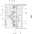
- While 1 shows the vehicle wheel rotary union 1 in a highly schematic manner, is in 2 a possible embodiment of a vehicle wheel rotary union 11 is shown in a half longitudinal section and in greater structural detail.
- the vehicle wheel rotary feedthrough 11 is ring-like overall, the contour of the ring in the half longitudinal section shown being determined by the outer contours of the rotary feedthrough parts 15, 18.
- the second rotary feedthrough part 18 is formed in two parts for assembly reasons.
- a central bearing 19 enables the second rotary feedthrough part 18 to be supported on the first rotary feedthrough part 15, enabling rotation, with the rolling elements 24 of the bearing 19 being supported on the one hand by the outer lateral surface of the rotary feedthrough part 15 and by the two parts of the rotary feedthrough part 18 with their inner surfaces or their mutually facing end regions are supported.
- the bearing 19 preferably has a bearing cage for the rolling elements 24.
- the rotary leadthrough part 15 has a first channel 25.
- the second rotary leadthrough part 18 has a second channel 26.
- a transition area 27 is formed in the transition area from the first channel 25 of the first rotary leadthrough part 15 to the second channel 26 of the second rotary leadthrough part 18.
- the first channel 25 starts at the supply input connection 20 .
- the second channel 26 leads to the supply output connection 10.
- the first channel 25 has an axial bore 28, which starts from the supply inlet connection 20 and is designed as a blind hole, and a branch bore 29, starting from the axial bore 28, which leads to the lateral surface of the rotary leadthrough part 15.
- the second channel 26 transitions from a circumferential groove 30 running in the circumferential direction into a connection section 61 with an enlarged cross section, via which the supply outlet connection 10 is provided.
- a branch line duct 31 , 32 branches off from the axial bore 28 (or also the branch bore 29 ) on both sides of the branch bore 29 .
- the branch line channel 31, 32 leads to a sealing effect control chamber 33, 34, which can only extend in at least a partial peripheral region, but preferably extends over the entire periphery and is designed as a peripheral groove.
- the branch line channels 31, 32 thus form sealing control channels 75, 76.
- the sealing effect control chambers 33, 34 and the associated sealing control channels 75, 76 are arranged in the axial direction on both sides of the branch hole 29 and the transition area 27.
- a sealing element 35 , 36 is arranged in each of the sealing effect control chambers 33 , 34 .
- the sealing elements 35, 36 are inserted into the sealing effect control chambers 33, 34 in a prestressed manner in such a way that they can be sealed by means of axial sealing surfaces 37, 38 (the 2 are shown only for the sealing element 36) are pressed against the limiting walls of the sealing effect control chambers 33, 34.
- the sealing elements 35, 36 form a type of (annular) piston in the sealing effect control chambers 33, 34, so that these can be acted upon by pressurizing the sealing effect control chambers 33, 34 like a piston in the radial direction and can be displaced or deformed in this direction.
- sealing elements 35, 36 and cylindrical sealing surfaces 39, 40 which are inner surfaces of the second rotary leadthrough part 18, sealing elements 41, 42 are caught and braced (at least when the supply pressure is present at the supply inlet connection 20).
- the sealing elements 35, 36 are pressed radially outwards against the sealing elements 41, 42, which causes sealing surfaces to form between the sealing elements 35, 41 and 36, 42 43, 44 training.
- the pairs of sealing elements 35, 41 and 36, 42 each form sealing units 45, 46.
- the sealing units 45, 46 extend in the form of a ring in the circumferential direction around the axis of rotation of the vehicle wheel rotary leadthrough 11.
- the sealing elements 35, 36 are preferably in the form of O-rings 47 , 48 trained.
- the sealing elements 41, 42 can be designed as inherently rigid slide rings 49, 50 or wear rings.
- Compressed air supply can reach the supply outlet connection 10 from the supply inlet connection via the first duct 25, the transition area 27, the second duct 26, with a sealing is guaranteed.
- a circumferential groove 51 with associated sealing units 52, 53 can also be seen, which are arranged axially on the other side of the bearing 19 here.
- the circumferential groove 51 is in 2 not shown, in a circumferentially offset partial longitudinal section connected to the control output port 13 via a corresponding second channel of the rotary leadthrough part 18, while in this circumferentially offset half longitudinal section a first channel of the rotary leadthrough part 15 is connected to the control input terminal 21.
- the vehicle wheel rotary leadthrough 11 can also be used to transmit the control pressure.
- This embodiment of the vehicle wheel rotary joint 11 is in 1 represented symbolically with the sealing units 45, 46, 52, 53, the branch line ducts 31, 32 and the branch line ducts 54, 55 assigned to the sealing units 52, 53.
- the vehicle wheel rotary union 11 is shown with half longitudinal sections produced at different circumferential angles.
- the half longitudinal section 3 it can be seen that (basically as before for 2 explained) a first channel 56 in the form of a blind hole-shaped axial bore 57, which emanates from the control input port 21, and a tap hole 58 is formed. Transmission takes place via a transition area 59 to the second channel 60 which is formed with the circumferential groove 51 and (in a half longitudinal section not shown here) is connected to the control output connection 13 via a connection section 61 .
- This also applies to the sealing via the two sealing units 52, 53.
- the sealing effect control chambers 62, 63 assigned to the sealing units 52, 53 are not subjected to the pressure at the control input connection 21. Rather, in the half-longitudinal section, which is in 4 is shown, an additional seal control connection 64 with associated axial bore 65 and branching therefrom, leading to the sealing effect control chambers 62, 63 branch line channels 54, 55 present.
- a seal control valve 68 can be used to generate a seal control pressure for the seal control port 64 and thus for the loading of the sealing effect control chambers 62, 63, so that the sealing force of the sealing units 52, 53 is independent of the transmitted control pressure, which is applied to the control input port 21, can be specified.
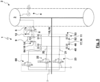
- FIG 5 is basically a tire inflation system 1 according to 1 shown.
- the seal control pressure does not correspond to the pressure that is to be transmitted via the transfer cross-sections and that is in 1 is specified by the supply valve 22 and the control valve 23. Rather, an additional sealing control valve 68 is present here.
- the seal control valve 68 is controlled electronically or pilot-controlled electro-pneumatically and is designed as a 3/2-way valve with a ventilation position and a venting position.
- the pressure output by the seal control valve 68 is supplied to a seal control connection 64 .
- the seal control pressure then passes from the seal control connection 64 to the sealing effect control chambers of the sealing units 45, 46, 52, 53.
- the sealing effect and the contact pressure force of the sealing units 45, 46, 52, 53 can thus be controlled independently of the activation of the Supply valve 22 and the control valve 23 take place.
- FIG 6 shows the optional equipment of the rotary leadthrough part 15 with a lubricant connection 70 . It is optionally possible for axial tapholes 73, 74 to branch off from the taphole 72 in both axial directions.
- the lubricant can also be supplied to additional running or bearing surfaces or intermediate spaces between the rotary leadthrough parts 15, 18 via the tapholes 73, 74.
- Such a lubricant supply preferably takes place according to FIG 6 Use together with a tire inflation device 1 according to figure 5 , in which the generation of a seal control pressure takes place separately via a seal control valve 68.
- the outlet-side connections can be provided on the lateral surface of the second rotary leadthrough part 18 .
- connections 80 can also be provided on an axial end face of the second rotary leadthrough part 18, in which case this at least one connection 80 can be a supply output connection 10 and/or a control output connection 13, for example.
- a fastening section 81 in particular a fastening bore, can be provided on the first rotary leadthrough part 15 .
- the sealing units 45, 46, 52, 53 namely the sealing elements 41, 42 designed as sliding rings 49, 50, each have a slot 69.
- the slots 69 are not formed in a straight line, but are rather stepped, with transverse surfaces 82 having a first spacing or directly contacting one another, enabling a sliding movement, while end surfaces 83, 84, the surface normals of which are oriented in the circumferential direction, a second Have distance that is greater than the first distance. This second distance depends on the elastic widening of the slip rings 49, 50.
- the distances between the transverse surfaces 82 and the end faces 83, 84 can be used to predetermine a throttling effect for compressed air to pass over.
- a leakage flow can pass through the slot 69 through the sealing units 45, 46, 52, 53, which may be desirable in order to flow through a (guiding) gap 85 formed between the rotary leadthrough parts 15, 18.
- This flow through the gap 85 can help to discharge particles from the gap 85 into the environment and to prevent particles or impurities from entering the gap 85 .
- the gap 85 can also be designed as a kind of labyrinth gap.
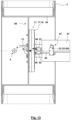
- the vehicle wheel assembly 86 shows a vehicle wheel assembly 86 in a longitudinal section.
- the vehicle wheel assembly 86 has a vehicle wheel carrier 87.
- the vehicle wheel 2 is mounted on the vehicle wheel carrier 87 via a wheel bearing 88, not shown in detail, in such a way that the wheel bearing 88 Wheel load of the vehicle wheel 2 is supported.
- the vehicle wheel 2 has a rim 89.
- the supply valve 22, the control valve 23 and the seal control valve 68 are held on the vehicle wheel carrier 87, from which a supply line 90, a control line 91 and a seal control line 92 emanate.
- the supply line 90 is connected to the supply input port 20 of the vehicle wheel swivel 11.
- the control line 91 is connected to the control input port 21 of the vehicle wheel swivel 11.
- the seal control line 92 is connected to the seal control port 64 of the vehicle wheel Rotating union 11.
- the second rotary feedthrough part 18 is fastened to the rim 89.
- the first rotary feedthrough part 15 is supported on the vehicle wheel carrier 87 via a torque support 93.
- the end region of the torque arm 93 facing away from the vehicle wheel carrier 87 is fastened to the fastening section 81 of the first rotary leadthrough part 15 .
- connections 80 of the vehicle wheel rotary leadthrough 11 arranged on the axial end face of the second rotary leadthrough part 18 are used.
- the tire pressure supply line 9 and the tire pressure control line 12 extend from these (through corresponding bores and connections in the rim 89) to the tire pressure control valve 5, whose output connection penetrates the rim well 94 of the rim 89 and opens directly into the interior of the tire 3.
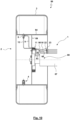
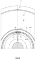
- 11 12 shows a front view of the vehicle wheel assembly 86 of FIG 10 .
- the torque arm 93 is fork-shaped in the fastening area on the vehicle wheel rotary union 11, the fork 95 having a connecting piece 96 for connecting the supply line 90 and/or of the control line 91 and/or the sealing control line 92 to the associated input connections of the vehicle wheel rotary union 11 in both circumferential directions and is supported in this way on the connection piece 96 .
- the supply valve 22, the control valve 23 and the seal control valve 68 can be part of a valve unit 97, it also being possible for the control of the seal control pressure, the control pressure and of the supply pressure is carried out by a single valve body occupying several different positions.
Landscapes
- Engineering & Computer Science (AREA)
- Mechanical Engineering (AREA)
- Mechanical Sealing (AREA)
Claims (15)
- Passage rotatif de roue de véhicule sans charge de roue (11) aveca) une première partie de passage rotatif (15), qui comprend un premier canal (25),b) une deuxième partie de passage rotatif (18) rotatif par rapport à la première partie de passage rotatif (15), qui comprend un deuxième canal (26),c) une zone de dépassement (27) réalisée entre les parties de passage rotatif (15, 18), quica) relie de manière pneumatique le premier canal (25) avec le deuxième canal (26) etcb) est étanchéifiée par l'intermédiaire d'unité d'étanchéité (45, 46) avec une action d'étanchéification,d) une chambre de contrôle d'effet d'étanchéité (33 ; 34),da) dans laquelle débouche un canal de contrôle d'étanchéité (75 ; 76) par l'intermédiaire duquel la chambre de contrôle d'effet d'étanchéité (33 ; 34) peut être sollicitée avec une pression de contrôle d'étanchéité etdb) qui est fermée par l'unité d'étanchéité (45, 46) sous la forme d'un piston coulissant, dans lequel l'effet d'étanchéité de l'unité d'étanchéité (45, 46) peut être modifié en fonction de la pression de contrôle d'étanchéité dans la chambre de contrôle d'effet d'étanchéité (33 ; 34),caractérisé en ce quee) la chambre de contrôle d'effet d'étanchéité (33 ; 34) est fermée à l'exception de la liaison avec le canal de contrôle d'étanchéité (75 ; 76), de façon à ce qu'elle ne soit pas traversée.
- Passage rotatif de roue de véhicule (11) selon la revendication 1, caractérisé en ce que la pression de contrôle d'étanchéité dans la chambre de contrôle d'effet d'étanchéité (33 ; 34) sollicite l'unité d'étanchéité (45, 46) dans la direction radiale avec une force d'étanchéité et comprime l'unité d'étanchéité (45, 46) contre une surface d'étanchéité cylindrique (39, 40) d'une partie de passage rotatif (18).
- Passage rotatif de roue de véhicule (11) selon la revendication 2, caractérisé en ce quea) l'unité d'étanchéité (45, 46)aa) comprend un élément d'étanchéité (41 ; 42) qui garantit l'étanchéité au niveau de la surface d'étanchéité cylindrique (39 ; 40) d'une partie de passage de roue rotatif (18) etab) comprend un deuxième élément d'étanchéité (35 ; 36) qui garantit une étanchéité par rapport à la chambre de contrôle d'effet d'étanchéité (33 ; 34), qui est réalisé dans l'autre partie de passage de roue rotatif (15),b) dans lequel le premier élément d'étanchéité (41 ; 42) et le deuxième élément d'étanchéité (35 ; 36) sont comprimés l'un contre l'autre lors d'une sollicitation de la chambre de contrôle d'effet d'étanchéité (33 ; 34) avec la pression de contrôle d'étanchéité dans la direction radiale afin de garantir une étanchéité.
- Passage rotatif de roue de véhicule (11) selon la revendication 3, caractérisé en ce quea) le premier élément d'étanchéité (41 ; 42) est une bague glissante intrinsèquement rigide (49 ; 50) et/oub) le deuxième élément d'étanchéité (35 ; 36) est une bague d'étanchéité élastique ou un joint torique (47 ; 48).
- Passage rotatif de roue de véhicule (11) selon la revendication 4, caractérisé en ce que la bague glissante intrinsèquement rigide (49 ; 50) présente une fente.
- Passage rotatif de roue de véhicule (11) selon la revendication 5, caractérisé en ce que la fente n'est pas réalisée en ligne droite.
- Passage rotatif de roue de véhicule (11) selon l'une des revendications précédentes, caractérisé en ce que la rigidité de l'unité d'étanchéité (45, 46) ou de la bague glissante (49 ; 50) est dimensionnée de façon à ce quea) le rayon de l'unité d'étanchéité (45, 46) ou de la bague glissante (49 ; 50) peut être agrandi de manière élastique avec une augmentation de la pression de contrôle d'étanchéité agissant dans la chambre de contrôle d'effet d'étanchéité (33 ; 34), ce qui permet de comprimer l'unité d'étanchéité (45, 46) ou la bague glissante (49 ; 50) avec une force de compression croissante contre la surface d'étanchéité (39 ; 40) et/oub) le rayon de l'unité d'étanchéité (45, 46) ou de la bague glissante (49 ; 50) peut être réduite de manière élastique avec une réduction de la pression de contrôle d'étanchéité agissant dans la chambre de contrôle d'effet d'étanchéité (33 ; 34), ce qui permet de réduire la force d'étanchéité entre l'unité d'étanchéité (45, 46) ou de la bague glissante (49 ; 50) et la surface d'étanchéité (39 ; 40).
- Passage rotatif de roue de véhicule (11) selon l'une des revendications précédentes, caractérisé en ce que la chambre de contrôle d'effet d'étanchéité (33 ; 34) et la zone de débordement (27) sont reliées entre elles de manière pneumatique de façon à ce que la pression de contrôle d'étanchéité et la pression dans la zone de débordement (27) dépendent l'une de l'autre.
- Passage rotatif de roue de véhicule (11) selon l'une des revendications précédentes, caractérisé en ce que la chambre de contrôle d'effet d'étanchéité (33 ; 34) et la zone de débordement (27) sont séparées l'une de l'autre de manière pneumatique, de façon à ce que la pression de contrôle d'étanchéité et la pression dans la zone de débordement (27) soient indépendantes l'une de l'autre.
- Passage rotatif de roue de véhicule (11) selon la revendication 9, caractérisé en ce quea) un raccord d'entrée de contrôle (21) ou un raccord d'entrée d'alimentation (20) est prévu, qui est relié avec le premier canal (25) et, par l'intermédiaire de la zone de débordement (27), avec le deuxième canal (26) etb) un raccord de contrôle d'étanchéité (64) est prévu, qui est relié avec la chambre de contrôle d'effet d'étanchéité (33 ; 34).
- Passage rotatif de roue de véhicule (11) selon l'une des revendications précédentes, caractérisé en ce qu'un raccord de lubrifiant (70) est prévu qui est relié avec un palier (19) par l'intermédiaire duquel les parties de passage rotatif (15, 18) sont logées de manière rotative entre elles.
- Sous-ensemble de roue de véhicule (86) aveca) un support de roue de véhicule (87),b) une roue de véhicule (2) avec un pneu (3), rotative par rapport au support de roue de véhicule (87) etc) un dispositif de gonflage de pneu (1) quica) dispose d'une conduite d'alimentation (90) qui sort du support de roue de véhicule (87) et qui met à disposition une pression d'alimentation par l'intermédiaire de laquelle un gonflage du pneu (3) peut avoir lieu oucb) dispose d'une conduite de contrôle (91) qui sort du support de roue de véhicule (87) et par l'intermédiaire de laquelle un gonflage, un blocage et/ou un dégonflage du pneu (3) peut être contrôlé,d) dans lequel le dispositif de gonflage de pneu (1) comprend un passage rotatif de roue de véhicule (11) selon l'une des revendications précédentes, par l'intermédiaire de laquelle une transmission de la pression d'alimentation ou de la pression de contrôle a lieu, grâce au fait que la conduite d'alimentation (90) ou la conduite de contrôle (91) s'étend par l'intermédiaire du premier canal (25), de la zone de débordement (27) et du deuxième canal (26),e) dans lequel, plus particulièrement, la roue de véhicule (2) est logée, par l'intermédiaire d'un palier de roue (88), au niveau du support de roue de véhicule (87) et le passage rotatif de roue de véhicule (11) est branché en parallèle du flux de force, de la roue du véhicule (2), par l'intermédiaire du palier de roue (88), vers le support de roue de véhicule (87), la deuxième partie de passage rotatif (18) étant par exemple pour cela fixée à la roue du véhicule (2) et la première partie de passage rotatif (15) est reliée, par l'intermédiaire des conduites raccordées et par l'intermédiaire d'un support de couple (93), avec le support de roue de véhicule (87).
- Engin de travail automobile avec au moins un sous-ensemble de roue de véhicule selon la revendication 12.
- Procédé de fonctionnement d'un passage rotatif de roue de véhicule (11), plus particulièrement d'un passage rotatif de roue de véhicule (11) selon l'une des revendications 1 à 11, avec les étapes suivantes :a) sollicitation d'un raccord d'entrée de contrôle (21) avec une pression de contrôle ou d'un raccord d'entrée d'alimentation (20) avec une pression d'alimentation,b) sollicitation d'une chambre de contrôle d'effet d'étanchéité (33 ; 34) avec une pression de contrôle d'étanchéité et production d'une force d'étanchéité afin de provoquer ou d'augmenter un effet d'étanchéité d'au moins une unité d'étanchéité (45 ; 46 ; 52 ; 53) etc) réduction de la pression de contrôle d'étanchéité dans la chambre de contrôle d'effet d'étanchéité (33 ; 34) et réduction de la force d'étanchéité afin de réduire l'effet d'étanchéité d'au moins une unité d'étanchéité (45 ; 46 ; 52 ; 53), lorsqu'aucune pression d'alimentation ou aucune pression de contrôle ne doit être transmise par l'intermédiaire du passage rotatif de roue de véhicule (11).
- Procédé selon la revendication 14, caractérisé en ce que, simultanémenta) un raccord de lubrifiant (70) est alimenté avec un lubrifiant pour un palier (19)b) un raccord de contrôle d'étanchéité (64) est sollicité avec une pression de contrôle d'étanchéité.
Priority Applications (1)
| Application Number | Priority Date | Filing Date | Title |
|---|---|---|---|
| EP20164579.3A EP3882048B1 (fr) | 2020-03-20 | 2020-03-20 | Passage tournant de roue de véhicule, module de roue de véhicule, machine de travail automobile et procédé de fonctionnement d'un passage tournant de roue de véhicule |
Applications Claiming Priority (1)
| Application Number | Priority Date | Filing Date | Title |
|---|---|---|---|
| EP20164579.3A EP3882048B1 (fr) | 2020-03-20 | 2020-03-20 | Passage tournant de roue de véhicule, module de roue de véhicule, machine de travail automobile et procédé de fonctionnement d'un passage tournant de roue de véhicule |
Publications (3)
| Publication Number | Publication Date |
|---|---|
| EP3882048A1 EP3882048A1 (fr) | 2021-09-22 |
| EP3882048C0 EP3882048C0 (fr) | 2023-06-07 |
| EP3882048B1 true EP3882048B1 (fr) | 2023-06-07 |
Family
ID=69941255
Family Applications (1)
| Application Number | Title | Priority Date | Filing Date |
|---|---|---|---|
| EP20164579.3A Active EP3882048B1 (fr) | 2020-03-20 | 2020-03-20 | Passage tournant de roue de véhicule, module de roue de véhicule, machine de travail automobile et procédé de fonctionnement d'un passage tournant de roue de véhicule |
Country Status (1)
| Country | Link |
|---|---|
| EP (1) | EP3882048B1 (fr) |
Citations (1)
| Publication number | Priority date | Publication date | Assignee | Title |
|---|---|---|---|---|
| EP3730321A1 (fr) * | 2019-04-23 | 2020-10-28 | Reinhold Schulte | Installation de commande de la pression de pneu du véhicule agricole |
Family Cites Families (1)
| Publication number | Priority date | Publication date | Assignee | Title |
|---|---|---|---|---|
| DE102018101411B4 (de) | 2018-01-23 | 2024-10-17 | Schaeffler Technologies AG & Co. KG | Dichtungsanordnung für eine Drehdurchführung eines Radlager eines Kraftfahrzeugs |
-
2020
- 2020-03-20 EP EP20164579.3A patent/EP3882048B1/fr active Active
Patent Citations (1)
| Publication number | Priority date | Publication date | Assignee | Title |
|---|---|---|---|---|
| EP3730321A1 (fr) * | 2019-04-23 | 2020-10-28 | Reinhold Schulte | Installation de commande de la pression de pneu du véhicule agricole |
Also Published As
| Publication number | Publication date |
|---|---|
| EP3882048C0 (fr) | 2023-06-07 |
| EP3882048A1 (fr) | 2021-09-22 |
Similar Documents
| Publication | Publication Date | Title |
|---|---|---|
| EP1095799B1 (fr) | Installation de réglage de la pression de pneus | |
| EP1731804B1 (fr) | Joint d'étanchéité et assemblage comportant des lèvres d'étanchéité en série | |
| WO2008095470A1 (fr) | Essieu et arbre d'entraînement ou de transmission pour véhicules à système central d'alimentation en pression de gonflage | |
| EP3320240A1 (fr) | Passage tourant pour un véhicule | |
| WO2017072140A1 (fr) | Passage tournant d'un système de régulation de pression de pneumatique ainsi qu'ensemble comportant un tel passage tournant et moyeu monté sur un tourillon d'essieu | |
| EP1874563B1 (fr) | Dispositif, en particulier passage tournant | |
| DE102017211574A1 (de) | Drehdurchführung für eine Reifenfüllanlage | |
| EP1179149B1 (fr) | Dispositif d'etancheite pour un piston soumis a l'action d'un fluide sous pression dans un cylindre de travail | |
| DE102014117458A1 (de) | Ventilanordnung für einen Dreh-Fest-Übergang, Radeinheit mit einem Dreh-Fest-Übergang, sowie Druckmittelversorgungseinrichtung für eine Radeinheit | |
| EP1338443A2 (fr) | Jonction rotative pour un dispositif pour gonfler ou dégonfler un pneu d'une roue de tracteur | |
| DE102007027147B4 (de) | Drehdurchführung für ein unter Druck durchführbares Medium | |
| EP3713779B1 (fr) | Ensemble d'étanchéité destiné à un passage tournant d'un palier de roue d'un véhicule automobile | |
| EP3882048B1 (fr) | Passage tournant de roue de véhicule, module de roue de véhicule, machine de travail automobile et procédé de fonctionnement d'un passage tournant de roue de véhicule | |
| DE102013207855A1 (de) | Lager mit Drehdurchführung | |
| EP4334622A1 (fr) | Raccord union rotatif multi-milieux et son procédé de fonctionnement | |
| DE102011014025B4 (de) | Fahrzeug, insbesondere Landmaschine | |
| DE102017223349A1 (de) | Lageranordnung für einen Radkopf, Verfahren zur Montage der Lageranordnung sowie Radkopf mit der Lageranordnung | |
| DE102005006073A1 (de) | Vorrichtung, insbesondere Drehdurchführung | |
| EP1488941B1 (fr) | Moyeu coaxial étanche a l'air pour la régulation de la pression interne des pneus, même lorsque le véhicule est en marche | |
| DE202020101527U1 (de) | Fahrzeugrad-Drehdurchführung, Fahrzeugrad-Baugruppe und selbstfahrende Arbeitsmaschine | |
| EP2837512B1 (fr) | Suspension | |
| DE102012003152B4 (de) | Verbindungsmittel zum Zu- und/oder Abführen eines Mediums an einem Achsschenkel | |
| EP0751016B1 (fr) | Dispositif d'étanchéification d'un conduit de gaz | |
| DE10302444B4 (de) | Radlagerung für ein Fahrzeugrad | |
| WO2014135164A1 (fr) | Passage tournant et installation de régulation de la pression d'un pneumatique pourvue d'un passage tournant |
Legal Events
| Date | Code | Title | Description |
|---|---|---|---|
| PUAI | Public reference made under article 153(3) epc to a published international application that has entered the european phase |
Free format text: ORIGINAL CODE: 0009012 |
|
| STAA | Information on the status of an ep patent application or granted ep patent |
Free format text: STATUS: THE APPLICATION HAS BEEN PUBLISHED |
|
| AK | Designated contracting states |
Kind code of ref document: A1 Designated state(s): AL AT BE BG CH CY CZ DE DK EE ES FI FR GB GR HR HU IE IS IT LI LT LU LV MC MK MT NL NO PL PT RO RS SE SI SK SM TR |
|
| STAA | Information on the status of an ep patent application or granted ep patent |
Free format text: STATUS: REQUEST FOR EXAMINATION WAS MADE |
|
| 17P | Request for examination filed |
Effective date: 20220316 |
|
| RBV | Designated contracting states (corrected) |
Designated state(s): AL AT BE BG CH CY CZ DE DK EE ES FI FR GB GR HR HU IE IS IT LI LT LU LV MC MK MT NL NO PL PT RO RS SE SI SK SM TR |
|
| STAA | Information on the status of an ep patent application or granted ep patent |
Free format text: STATUS: EXAMINATION IS IN PROGRESS |
|
| 17Q | First examination report despatched |
Effective date: 20220530 |
|
| RIC1 | Information provided on ipc code assigned before grant |
Ipc: B60C 23/04 20060101ALI20221107BHEP Ipc: B60C 23/00 20060101ALI20221107BHEP Ipc: B60C 1/00 20060101AFI20221107BHEP |
|
| GRAP | Despatch of communication of intention to grant a patent |
Free format text: ORIGINAL CODE: EPIDOSNIGR1 |
|
| STAA | Information on the status of an ep patent application or granted ep patent |
Free format text: STATUS: GRANT OF PATENT IS INTENDED |
|
| INTG | Intention to grant announced |
Effective date: 20230112 |
|
| GRAS | Grant fee paid |
Free format text: ORIGINAL CODE: EPIDOSNIGR3 |
|
| GRAA | (expected) grant |
Free format text: ORIGINAL CODE: 0009210 |
|
| STAA | Information on the status of an ep patent application or granted ep patent |
Free format text: STATUS: THE PATENT HAS BEEN GRANTED |
|
| AK | Designated contracting states |
Kind code of ref document: B1 Designated state(s): AL AT BE BG CH CY CZ DE DK EE ES FI FR GB GR HR HU IE IS IT LI LT LU LV MC MK MT NL NO PL PT RO RS SE SI SK SM TR |
|
| REG | Reference to a national code |
Ref country code: GB Ref legal event code: FG4D Free format text: NOT ENGLISH |
|
| REG | Reference to a national code |
Ref country code: CH Ref legal event code: EP Ref country code: AT Ref legal event code: REF Ref document number: 1573935 Country of ref document: AT Kind code of ref document: T Effective date: 20230615 Ref country code: DE Ref legal event code: R096 Ref document number: 502020003461 Country of ref document: DE |
|
| U01 | Request for unitary effect filed |
Effective date: 20230619 |
|
| U07 | Unitary effect registered |
Designated state(s): AT BE BG DE DK EE FI FR IT LT LU LV MT NL PT SE SI Effective date: 20230626 |
|
| REG | Reference to a national code |
Ref country code: LT Ref legal event code: MG9D |
|
| PG25 | Lapsed in a contracting state [announced via postgrant information from national office to epo] |
Ref country code: NO Free format text: LAPSE BECAUSE OF FAILURE TO SUBMIT A TRANSLATION OF THE DESCRIPTION OR TO PAY THE FEE WITHIN THE PRESCRIBED TIME-LIMIT Effective date: 20230907 Ref country code: ES Free format text: LAPSE BECAUSE OF FAILURE TO SUBMIT A TRANSLATION OF THE DESCRIPTION OR TO PAY THE FEE WITHIN THE PRESCRIBED TIME-LIMIT Effective date: 20230607 |
|
| PG25 | Lapsed in a contracting state [announced via postgrant information from national office to epo] |
Ref country code: RS Free format text: LAPSE BECAUSE OF FAILURE TO SUBMIT A TRANSLATION OF THE DESCRIPTION OR TO PAY THE FEE WITHIN THE PRESCRIBED TIME-LIMIT Effective date: 20230607 Ref country code: HR Free format text: LAPSE BECAUSE OF FAILURE TO SUBMIT A TRANSLATION OF THE DESCRIPTION OR TO PAY THE FEE WITHIN THE PRESCRIBED TIME-LIMIT Effective date: 20230607 Ref country code: GR Free format text: LAPSE BECAUSE OF FAILURE TO SUBMIT A TRANSLATION OF THE DESCRIPTION OR TO PAY THE FEE WITHIN THE PRESCRIBED TIME-LIMIT Effective date: 20230908 |
|
| PG25 | Lapsed in a contracting state [announced via postgrant information from national office to epo] |
Ref country code: SK Free format text: LAPSE BECAUSE OF FAILURE TO SUBMIT A TRANSLATION OF THE DESCRIPTION OR TO PAY THE FEE WITHIN THE PRESCRIBED TIME-LIMIT Effective date: 20230607 |
|
| PG25 | Lapsed in a contracting state [announced via postgrant information from national office to epo] |
Ref country code: IS Free format text: LAPSE BECAUSE OF FAILURE TO SUBMIT A TRANSLATION OF THE DESCRIPTION OR TO PAY THE FEE WITHIN THE PRESCRIBED TIME-LIMIT Effective date: 20231007 |
|
| PG25 | Lapsed in a contracting state [announced via postgrant information from national office to epo] |
Ref country code: SM Free format text: LAPSE BECAUSE OF FAILURE TO SUBMIT A TRANSLATION OF THE DESCRIPTION OR TO PAY THE FEE WITHIN THE PRESCRIBED TIME-LIMIT Effective date: 20230607 Ref country code: SK Free format text: LAPSE BECAUSE OF FAILURE TO SUBMIT A TRANSLATION OF THE DESCRIPTION OR TO PAY THE FEE WITHIN THE PRESCRIBED TIME-LIMIT Effective date: 20230607 Ref country code: RO Free format text: LAPSE BECAUSE OF FAILURE TO SUBMIT A TRANSLATION OF THE DESCRIPTION OR TO PAY THE FEE WITHIN THE PRESCRIBED TIME-LIMIT Effective date: 20230607 Ref country code: IS Free format text: LAPSE BECAUSE OF FAILURE TO SUBMIT A TRANSLATION OF THE DESCRIPTION OR TO PAY THE FEE WITHIN THE PRESCRIBED TIME-LIMIT Effective date: 20231007 Ref country code: CZ Free format text: LAPSE BECAUSE OF FAILURE TO SUBMIT A TRANSLATION OF THE DESCRIPTION OR TO PAY THE FEE WITHIN THE PRESCRIBED TIME-LIMIT Effective date: 20230607 |
|
| U20 | Renewal fee for the european patent with unitary effect paid |
Year of fee payment: 5 Effective date: 20240112 |
|
| PG25 | Lapsed in a contracting state [announced via postgrant information from national office to epo] |
Ref country code: PL Free format text: LAPSE BECAUSE OF FAILURE TO SUBMIT A TRANSLATION OF THE DESCRIPTION OR TO PAY THE FEE WITHIN THE PRESCRIBED TIME-LIMIT Effective date: 20230607 |
|
| REG | Reference to a national code |
Ref country code: DE Ref legal event code: R097 Ref document number: 502020003461 Country of ref document: DE |
|
| PLBE | No opposition filed within time limit |
Free format text: ORIGINAL CODE: 0009261 |
|
| STAA | Information on the status of an ep patent application or granted ep patent |
Free format text: STATUS: NO OPPOSITION FILED WITHIN TIME LIMIT |
|
| 26N | No opposition filed |
Effective date: 20240308 |
|
| REG | Reference to a national code |
Ref country code: CH Ref legal event code: PL |
|
| PG25 | Lapsed in a contracting state [announced via postgrant information from national office to epo] |
Ref country code: MC Free format text: LAPSE BECAUSE OF FAILURE TO SUBMIT A TRANSLATION OF THE DESCRIPTION OR TO PAY THE FEE WITHIN THE PRESCRIBED TIME-LIMIT Effective date: 20230607 |
|
| GBPC | Gb: european patent ceased through non-payment of renewal fee |
Effective date: 20240320 |
|
| PG25 | Lapsed in a contracting state [announced via postgrant information from national office to epo] |
Ref country code: MC Free format text: LAPSE BECAUSE OF FAILURE TO SUBMIT A TRANSLATION OF THE DESCRIPTION OR TO PAY THE FEE WITHIN THE PRESCRIBED TIME-LIMIT Effective date: 20230607 |
|
| PG25 | Lapsed in a contracting state [announced via postgrant information from national office to epo] |
Ref country code: GB Free format text: LAPSE BECAUSE OF NON-PAYMENT OF DUE FEES Effective date: 20240320 |
|
| PG25 | Lapsed in a contracting state [announced via postgrant information from national office to epo] |
Ref country code: IE Free format text: LAPSE BECAUSE OF NON-PAYMENT OF DUE FEES Effective date: 20240320 |
|
| PG25 | Lapsed in a contracting state [announced via postgrant information from national office to epo] |
Ref country code: IE Free format text: LAPSE BECAUSE OF NON-PAYMENT OF DUE FEES Effective date: 20240320 Ref country code: GB Free format text: LAPSE BECAUSE OF NON-PAYMENT OF DUE FEES Effective date: 20240320 Ref country code: CH Free format text: LAPSE BECAUSE OF NON-PAYMENT OF DUE FEES Effective date: 20240331 |
|
| U20 | Renewal fee for the european patent with unitary effect paid |
Year of fee payment: 6 Effective date: 20250129 |
|
| PG25 | Lapsed in a contracting state [announced via postgrant information from national office to epo] |
Ref country code: CY Free format text: LAPSE BECAUSE OF FAILURE TO SUBMIT A TRANSLATION OF THE DESCRIPTION OR TO PAY THE FEE WITHIN THE PRESCRIBED TIME-LIMIT; INVALID AB INITIO Effective date: 20200320 |
|
| PG25 | Lapsed in a contracting state [announced via postgrant information from national office to epo] |
Ref country code: HU Free format text: LAPSE BECAUSE OF FAILURE TO SUBMIT A TRANSLATION OF THE DESCRIPTION OR TO PAY THE FEE WITHIN THE PRESCRIBED TIME-LIMIT; INVALID AB INITIO Effective date: 20200320 |
|
| PG25 | Lapsed in a contracting state [announced via postgrant information from national office to epo] |
Ref country code: TR Free format text: LAPSE BECAUSE OF FAILURE TO SUBMIT A TRANSLATION OF THE DESCRIPTION OR TO PAY THE FEE WITHIN THE PRESCRIBED TIME-LIMIT Effective date: 20230607 |
|
| U20 | Renewal fee for the european patent with unitary effect paid |
Year of fee payment: 7 Effective date: 20260112 |