EP3882089B1 - Module de montage pour véhicule à moteur - Google Patents
Module de montage pour véhicule à moteur Download PDFInfo
- Publication number
- EP3882089B1 EP3882089B1 EP21165836.4A EP21165836A EP3882089B1 EP 3882089 B1 EP3882089 B1 EP 3882089B1 EP 21165836 A EP21165836 A EP 21165836A EP 3882089 B1 EP3882089 B1 EP 3882089B1
- Authority
- EP
- European Patent Office
- Prior art keywords
- laser light
- user
- motor vehicle
- detection area
- optical sensor
- Prior art date
- Legal status (The legal status is an assumption and is not a legal conclusion. Google has not performed a legal analysis and makes no representation as to the accuracy of the status listed.)
- Active
Links
Images




Classifications
-
- B—PERFORMING OPERATIONS; TRANSPORTING
- B60—VEHICLES IN GENERAL
- B60R—VEHICLES, VEHICLE FITTINGS, OR VEHICLE PARTS, NOT OTHERWISE PROVIDED FOR
- B60R25/00—Fittings or systems for preventing or indicating unauthorised use or theft of vehicles
- B60R25/20—Means to switch the anti-theft system on or off
- B60R25/2081—Means to switch the anti-theft system on or off combined with personal settings of other vehicle devices, e.g. mirrors, seats, steering wheels
-
- B—PERFORMING OPERATIONS; TRANSPORTING
- B60—VEHICLES IN GENERAL
- B60R—VEHICLES, VEHICLE FITTINGS, OR VEHICLE PARTS, NOT OTHERWISE PROVIDED FOR
- B60R25/00—Fittings or systems for preventing or indicating unauthorised use or theft of vehicles
- B60R25/20—Means to switch the anti-theft system on or off
- B60R25/24—Means to switch the anti-theft system on or off using electronic identifiers containing a code not memorised by the user
-
- B—PERFORMING OPERATIONS; TRANSPORTING
- B60—VEHICLES IN GENERAL
- B60R—VEHICLES, VEHICLE FITTINGS, OR VEHICLE PARTS, NOT OTHERWISE PROVIDED FOR
- B60R25/00—Fittings or systems for preventing or indicating unauthorised use or theft of vehicles
- B60R25/20—Means to switch the anti-theft system on or off
- B60R25/24—Means to switch the anti-theft system on or off using electronic identifiers containing a code not memorised by the user
- B60R25/245—Means to switch the anti-theft system on or off using electronic identifiers containing a code not memorised by the user where the antenna reception area plays a role
-
- G—PHYSICS
- G01—MEASURING; TESTING
- G01S—RADIO DIRECTION-FINDING; RADIO NAVIGATION; DETERMINING DISTANCE OR VELOCITY BY USE OF RADIO WAVES; LOCATING OR PRESENCE-DETECTING BY USE OF THE REFLECTION OR RERADIATION OF RADIO WAVES; ANALOGOUS ARRANGEMENTS USING OTHER WAVES
- G01S13/00—Systems using the reflection or reradiation of radio waves, e.g. radar systems; Analogous systems using reflection or reradiation of waves whose nature or wavelength is irrelevant or unspecified
- G01S13/02—Systems using reflection of radio waves, e.g. primary radar systems; Analogous systems
- G01S13/06—Systems determining position data of a target
- G01S13/08—Systems for measuring distance only
-
- G—PHYSICS
- G01—MEASURING; TESTING
- G01S—RADIO DIRECTION-FINDING; RADIO NAVIGATION; DETERMINING DISTANCE OR VELOCITY BY USE OF RADIO WAVES; LOCATING OR PRESENCE-DETECTING BY USE OF THE REFLECTION OR RERADIATION OF RADIO WAVES; ANALOGOUS ARRANGEMENTS USING OTHER WAVES
- G01S15/00—Systems using the reflection or reradiation of acoustic waves, e.g. sonar systems
- G01S15/02—Systems using the reflection or reradiation of acoustic waves, e.g. sonar systems using reflection of acoustic waves
- G01S15/06—Systems determining the position data of a target
- G01S15/08—Systems for measuring distance only
-
- G—PHYSICS
- G01—MEASURING; TESTING
- G01S—RADIO DIRECTION-FINDING; RADIO NAVIGATION; DETERMINING DISTANCE OR VELOCITY BY USE OF RADIO WAVES; LOCATING OR PRESENCE-DETECTING BY USE OF THE REFLECTION OR RERADIATION OF RADIO WAVES; ANALOGOUS ARRANGEMENTS USING OTHER WAVES
- G01S17/00—Systems using the reflection or reradiation of electromagnetic waves other than radio waves, e.g. lidar systems
- G01S17/02—Systems using the reflection of electromagnetic waves other than radio waves
- G01S17/06—Systems determining position data of a target
- G01S17/08—Systems determining position data of a target for measuring distance only
-
- G—PHYSICS
- G01—MEASURING; TESTING
- G01S—RADIO DIRECTION-FINDING; RADIO NAVIGATION; DETERMINING DISTANCE OR VELOCITY BY USE OF RADIO WAVES; LOCATING OR PRESENCE-DETECTING BY USE OF THE REFLECTION OR RERADIATION OF RADIO WAVES; ANALOGOUS ARRANGEMENTS USING OTHER WAVES
- G01S17/00—Systems using the reflection or reradiation of electromagnetic waves other than radio waves, e.g. lidar systems
- G01S17/02—Systems using the reflection of electromagnetic waves other than radio waves
- G01S17/06—Systems determining position data of a target
- G01S17/08—Systems determining position data of a target for measuring distance only
- G01S17/10—Systems determining position data of a target for measuring distance only using transmission of interrupted, pulse-modulated waves
Definitions
- the present invention relates to an assembly module for a motor vehicle and a method for triggering a signal for carrying out an action on a motor vehicle.
- environmental monitoring can be carried out in vehicles in order to carry out actions on the vehicle.
- so-called "keyless entry” and “keyless go” functions are used in vehicles.
- radio monitoring detects when a corresponding radio key, e.g. in a user's pocket, is located near the vehicle.
- An authentication action can then be carried out, in which a query can be used to determine whether the key matches the vehicle.
- the vehicle can then be opened or locked.
- Other methods of Monitoring e.g. in a capacitive manner, are known.
- State-of-the-art environmental monitoring for vehicles is known, for example, from the EN 10 2005 032 402 known.
- the detection area is further subdivided into a smaller operating area.
- This enables two levels of user detection. Firstly, the approach of the user is detected by permanently monitoring the detection area. More precise monitoring can now take place within the detection area, which is carried out selectively only when a user has been detected in the detection area.
- This distance measurement to the user now provides additional information, particularly in a third dimension, to the usual two-dimensional monitoring of the detection area.
- the distance measurement to the user therefore allows a volume of the activation area to be monitored in a third dimension, so to speak, starting from a two-dimensional detection area. This can ensure that, for example, small elements below the activation area, i.e. between the activation area and the floor surface, or parts of the user's body above the activation area no longer trigger the signal. This leads to a particularly cost-effective and simple reduction in the risk of false triggering.
- a wide variety of technical solutions can of course be used to measure distance, as will be explained later.
- a particularly preferred solution for measuring distance is the use of the so-called "TIME-OF-FLIGHT" determination with the emission of one or more pulsed laser light flashes and the reception of the reflection of this or these laser light flashes.
- the present invention is not limited to this technical solution, but can instead have different technical designs.
- the actuation area and preferably also the detection area, as a volume element.
- the volume elements of the actuation area or the detection area can be arranged on the floor surface or can float above this floor surface.
- the assembly module can be attached to the motor vehicle.
- An optical sensor system is understood to be a system that has one or more sensor units. These can be used to monitor the detection area optically.
- the sensor system can have a photo sensor that has individual photosensitive pixels. This makes it possible to provide an image, in particular a two-dimensional image, of the detection area and to use changes in the individual pixels as a basis for monitoring a user entering the detection area. In other words, the detection area can now be monitored purely optically and, above all, continuously.
- a detection area in the sense of the present invention is an area next to or outside the vehicle, which with a high degree of probability suggests a desired subsequent action by the user.
- a detection area can be arranged behind the vehicle and can be used to detect an action related to the Tailgate, e.g. the desire to open the tailgate.
- a corresponding detection area is formed next to the vehicle, e.g. in the area of the driver's door or the rear doors, in particular in the area of a sliding door. In such a case, the user entering this detection area would most likely indicate a desire to open the corresponding door.
- the optical sensor system or the entire assembly module can be designed for arrangement at the rear of the vehicle, e.g. behind the rear window, in a handle bar, in an emblem, in a tail light, behind a cat's eye, on a bumper and/or in a gap between two components.
- the assembly module can be suitable for being attached to a side of the vehicle, e.g. in a B-pillar. This allows different detection areas in which a user usually approaches the motor vehicle to be monitored with the optical sensor system.
- the optical sensor system or the entire assembly module can be hidden behind a layer that is opaque from the outside but is translucent for the light from the optical sensor system.
- the bumper on which the optical sensor system is mounted can be painted.
- the optical sensor system is preferably arranged on the motor vehicle in such a way that it becomes as dirty as possible.
- the optical sensor system can be arranged behind the rear window in the wiping area of the windshield wiper or on the handle bar.
- the assembly module can have a washer nozzle with which the optical sensor system can be cleaned.
- the washer nozzle can, for example, automatically clean the optical sensor system whenever the windshield wiper on the front and/or rear window is operated.
- a clean optical sensor system requires less light intensity to function, so that energy can also be saved in this way.
- a display element can have several lighting states. In one of the lighting states, such a display element can emit light of constant brightness. In another lighting state, for example, the brightness can change periodically. For example, at the start of the actuation period, the display element can emit light of constant brightness. During the removal period, the display element can flash, for example.
- the signal is only provided if the object, in particular a part of the user's body, is removed from the actuation area within the removal period.
- the position of the actuation area and/or the length of the actuation period can be changed. This is particularly helpful if a physically impaired user wants to express his or her user wishes. This is also helpful if the actuation area is located in a position that is unfavorable for the user.
- the unfavorable position can be permanent.
- the actuation area can end on a trailer hitch.
- the unfavorable position can only be unfavorable for triggering a one-off work signal, e.g. because the actuation area ends at a puddle.
- a predefined user action can be provided.
- the actuation area can be monitored again in order to determine the user's intention to trigger a work signal after an initial actuation period has ended without the user's intention being recognized. This is particularly helpful if the user was distracted and did not reach the actuation area in time or performed the wrong gesture. It can therefore be provided that the actuation area can be monitored several times, in particular two or three times, in a row. The renewed monitoring of the actuation area can be initiated automatically. Alternatively, a predefined user action can be provided to monitor the actuation area again for a further actuation period. For this purpose, a capacitive sensor can be addressed by the user, for example. Alternatively, it can be a predefined user action that is recognized by the optical sensor system.
- the predefined user action that is recognized by the optical sensor system and that causes a change in the position of the actuation area and/or the duration of actuation and/or a renewed monitoring of the actuation area to recognize a user's intention can be, for example, the following user actions: a predetermined gesture within the actuation and/or detection area, for example moving a body part of the user back and forth, not removing the body part if removal was intended, a movement of the user into the detection and/or actuation area and/or out of the detection and/or actuation area.
- the body part can be a hand or a foot. It can also be provided that the user leaves the detection area for a predetermined time and then returns to the detection area.
- the display element also shows this. If the position of the operating area is changed, the display element shows this.
- the display element can have several lights, e.g. LEDs, for this purpose. One or more lights make each operating area at least partially visible.
- the operating area with the changed position is within the detection area. Depending on which operating area is being monitored, the corresponding pixels are evaluated.
- the position of the ID transmitter is checked during or after authentication and before the signal is triggered.
- the strength of a signal sent by an ID transmitter can be used for this purpose.
- the Receive Signal Strength Indicator (RSSI) can be used for this purpose.
- RSSI Receive Signal Strength Indicator
- By determining the strength of the signal sent it can be determined, for example, whether the user is in front of, next to or behind the vehicle. This can ensure that only the authorized user has entered the detection area and has expressed his or her user intention in the activation area. It is conceivable to query the RSSI cyclically.
- the optical sensor system may not be designed to carry out step b) by means of an ultrasonic measurement.
- the TOF calculation mentioned above is also possible with ultrasound.
- the reflection of the ultrasound can allow a conclusion or a mathematical determination of the distance between the assembly module and the user or the user's body part.
- the use of ultrasound is therefore one possible design of the optical sensor system.
- the optical sensor system can be designed to carry out step b) using a radar measurement.
- a radar measurement is also possible in order to obtain corresponding distance information.
- the assembly module can also have a so-called PDC (Park Distance Control) functionality. In this way, it is possible to integrate existing sensors that are present in the motor vehicle into an optical sensor system of an assembly module according to the invention.
- PDC Park Distance Control
- the optical sensor module is designed to carry out step b) by evaluating at least two images of the detection area taken from different angles.
- a corresponding distance can be determined, for example, by phase shifting or, with knowledge of the angle, by means of a computational triangulation.
- This embodiment is an alternative to optical detection, to the laser flash method explained in more detail later.
- This solution can of course also be combined with other technical embodiments in order to carry out step b) with an assembly module according to the invention.
- the use of a laser light flash is particularly important for the additional detection of distance information from the user.
- the laser light flash can now be used to obtain three-dimensional information by detecting its reflection. While the simple optical sensor system is equipped with a photo sensor, for example, the laser light flash can add three-dimensional distance information in addition to the two-dimensional information of such a photo sensor. This makes it possible to define the detection area or in particular the activation area in terms of its distance from the vehicle or the assembly module.
- a laser flash By using a laser flash, it is possible to obtain the described 3D information. For example, a so-called "time of flight” (TOF) method can be used. The time that has passed between the emission of the laser flash and the reception of the reflection of the laser flash is determined. By correlating this with the speed of light, a distance calculation or distance determination can be carried out using this time difference. This means that the corresponding user can no longer only be recognized within the detection area or within the activation area, but this is also correlated with the distance information.
- TOF time of flight
- the use of a laser light flash according to the invention means that these areas can no longer only be designed two-dimensionally as a surface outside the vehicle, but the detection area and the actuation area can also be designed as a detection volume or actuation volume. It should be noted that an extension from the ground to a maximum height is of course possible for both the detection area as a volume and the actuation area as a volume. However, it can also be advantageous if two or more distance limits are specified, which now form a floating detection area or a floating operating area can be defined as a volume. This ensures that an unwanted standing within the operating area does not lead to a potentially unwanted triggering of the action by triggering the signal. This means that gestures can be recognized and predefined even more clearly and can be distinguished from other gestures that are not intended to trigger the action. The following is a brief example of how a method according to the invention or an assembly module according to the invention works.
- the assembly module is located in the rear of the vehicle, for example, it is used to trigger the opening request for automatic opening of the tailgate as a corresponding signal.
- the detection area behind the vehicle is continuously monitored. If the user now enters this detection area, this is recognized and an authentication step can take place beforehand, for example. If the user is confirmed as an authenticated user due to a radio key present, e.g. in his trouser pocket, the activation area can now be actively or passively monitored. If the user or a part of the user's body is detected within the activation area, the signal is triggered to carry out the action on the vehicle, namely the automatic opening of the tailgate. In other words, the user first enters the detection area and then has to move themselves or a part of their body into the activation area in order to trigger the desired signal to carry out the action on the vehicle with the help of the laser light flash in a three-dimensional information structure.
- a significantly higher level of security is now achieved for the implementation of the method or for the design of the assembly module. While with known solutions, a false opening could still occur, for example if the user of the vehicle is behind the vehicle with his radio key but has no desire to open the tailgate. In such a case, it could happen that the user accidentally moves into the operating area and then an opening desire or the desire to trigger the action is detected there in an undesirable manner.
- 3D information it is now possible for 3D information to have a significantly stronger restriction of the The activation area, particularly its height, is now allowed. This enables an improved differentiation of different gestures, which now significantly reduces the risk of the false triggering described above.
- a further advantage of an assembly module according to the invention is that, with the aid of the laser light flash, the fine determination of the three-dimensional information is only necessary with reference to the operating area.
- an assembly module according to the invention makes it possible to implement a two-stage process in which the laser light flash is used for the predefined operating area, in particular not continuously, but only when the user is detected within the detection area.
- a laser light flash is understood to mean any form of wavelength that falls under the term laser light.
- a flash for the laser light is formed when the laser light is not emitted continuously, but only for a very short period of time, preferably less than approximately one second.
- the laser light flash is emitted several times, so that it can also be referred to as a pulsed laser light flash. This will also be explained in more detail later.
- the optical sensor system is designed to trigger a signal for starting an authentication check between the ID transmitter and an access control system of the motor vehicle if the user is detected in the detection area, and to carry out steps b) to d) only if the authentication result is positive.
- the sensor system now only carries out its decisive triggering steps with the aid of the laser light flash if the authorized user is actually within the detection area. This ensures that the high energy requirement for emitting a laser light flash is only carried out if the authorized person is actually in the corresponding position in the detection area.
- the authentication step it is of course possible for the authentication step to only be carried out if the vehicle is locked. In an unlocked vehicle, it is therefore possible for the passenger, for example, to also or a person without a radio module in their pocket triggers the corresponding action.
- the optical sensor system is designed to suppress steps b) to c) if no user has been detected in the detection area.
- steps b) to c) can of course also be actively permitted or carried out if the user has been detected in the detection area.
- the high energy requirement which is necessary for generating laser light flashes, for example, is avoided with this continuous monitoring and is only carried out if the user has actually been detected within the detection area.
- This embodiment is particularly combined with the authentication check according to the previous paragraph. This avoids the high energy requirement for the laser light flash being carried out on every person who moves through the detection area. This achieves an even further improved reduction in the necessary energy requirement for the continuous operation of the assembly module.
- the optical sensor system has a transmitter unit for emitting a laser light flash with a wavelength in the infrared range, in particular with a wavelength in the range of 905 nm plus/minus approx. 10 nm.
- Laser light flashes with a wavelength in the infrared range have the advantage that they are not visible to the human eye. In this way, light influences, e.g. in a parking garage, are avoided.
- This embodiment is also advantageous because the user does not see them visually and the sensor system is thus invisible.
- the use of the laser light flash in the The infrared range can be used to achieve independence from ambient lighting.
- the infrared range is also advantageous in this case, as it can be more clearly and, above all, better distinguished from ambient scattered light or reflections of sunlight.
- the area in which the laser light flash is emitted is carried out as a wavelength peak that is as narrowly limited as possible. This means that even with a broad spectrum that is perceived as total reflection by the optical sensor device, the emitted and reflected laser light flash can be filtered out simply and, above all, mathematically.
- Energy can also be saved by using light of different wavelengths.
- the detection area can be monitored with light of a longer wavelength until any object in the detection area is detected once, rather than the subsequent checking of other requirements for detecting a user.
- light with a wavelength of 905 nm can be used initially. If an object is detected in the detection area, light with a wavelength of 800 nm can be used.
- the wavelength can be shortened when the object moves from the far to the near zone.
- the optical sensor system has at least one optical filter, in particular an infrared filter, for the optical filtering of an emitted laser light flash and/or the reflection of the laser light flash. It is preferred if this optical filter is provided exclusively in the transmitting unit or exclusively in the receiving unit. This makes it possible to reduce the reduction in the width of the emitted peak in the wavelength spectrum of the laser light pulse already described in the previous paragraph. This means that the emitted laser light flash can then be filtered out of a broad reflection spectrum in a specific and easier manner, in particular by calculation. Of course, a corresponding filter can also be used in an associated receiving unit. Because such an optical filter reduces the width of the spectrum of the emitted laser light flash in terms of its wavelength, simpler and above all more cost-effective light sources can be used for the laser light flash.
- an optical filter reduces the width of the spectrum of the emitted laser light flash in terms of its wavelength, simpler and above all more cost-effective light sources can be used for the laser light flash.
- the optical sensor system has at least one polarizer for the polarization of an emitted laser light flash and/or the reflection of the laser light flash.
- This polarizer can fulfill a similar function to the corresponding optical filter according to the previous paragraph.
- the polarizer can be arranged either on the transmitting unit or on the receiving unit or on both of these units.
- the optical sensor system has optics for expanding the Gaussian distribution of the intensity of an emitted laser light flash in order to supply the edges of the detection area with sufficiently high intensity.
- a fanning out of the emitted laser light flash is preferably homogenized. Since the emission of the laser light flash is an emission into the detection area, outer boundaries can be defined for this monitoring step or this matching step. These outer boundaries preferably coincide with the outer boundaries of the predefined actuation area, which has already been explained and is smaller than the detection area. These outer boundaries now serve to allow a demarcation between desired actuation and undesired actuation.
- a further advantage can be achieved if the optical sensor system in an assembly module according to the invention has a cylindrical or essentially cylindrical design.
- the cylinder axis of this design is preferably correlated, e.g. aligned along the emission direction of the laser light flash or other emission directions. This means that when assembling the assembly module and thus also the optical transmission unit, the desired alignment of the assembly module, which is also advantageous for the effect according to the invention, can be achieved easily and clearly.
- the optical sensor system is designed for an overlay, in particular a complete overlay, of the detection area and/or the actuation area with an emitted laser light flash.
- a corresponding transmitting unit of a sensor system preferably provides an opening cone for emitting the laser light flash. This light cone as a volume extension accordingly also overlays an associated volume extension of an actuation volume or the actuation area and a detection volume or the detection area.
- the optical sensor system has a control device with a transmitter unit for emitting a laser light flash, wherein the transmitter unit has an orientation with an emission direction at an acute angle to the horizontal, in particular with an angle greater than approximately 30°. In particular, this angle is directed downwards. Since laser light flashes are usually used for such embodiments with higher intensity, the downward orientation brings with it a safety gain. In particular, this also makes it possible to use energies which define a laser class in height that would have a damaging effect if they hit the user's eye. By aligning the emission direction downwards, the risk of entering the human eye when using such an optical system can be significantly reduced. At the same time, an alignment takes place to an operating area which preferably located on the floor or in the area of the floor, or just above the floor. If a side door is monitored, optical monitoring can be carried out in the area of the door handle.
- the optical sensor system has a control device for evaluating the time difference between the transmission of a transmission signal, in particular a laser light flash, and the detection of the reflection of the transmission signal, in particular the laser light flash, from the user in relation to the distance of the user from the optical sensor system.
- a control device for evaluating the time difference between the transmission of a transmission signal, in particular a laser light flash, and the detection of the reflection of the transmission signal, in particular the laser light flash, from the user in relation to the distance of the user from the optical sensor system.
- the TOF determination already mentioned is used here.
- the point in time at which the laser light flash is transmitted is determined.
- the point in time at which the reflection of the laser light flash is perceived by the user by a corresponding receiving unit of the optical sensor system is determined.
- the time difference between these two points in time can be determined.
- the time difference is used to determine the actual distance to the user by correlating it with the speed of light. This makes it possible to obtain three-dimensional information regarding the geometric positioning of the user within the
- the above list is not exhaustive.
- the opening and/or closing of the respective object i.e. the tailgate, the sliding door, the side door, the window, the hood or a corresponding sunroof, can preferably be done automatically.
- the user of the vehicle can now actively open or close the tailgate of the vehicle with a corresponding gesture.
- the automatic and thus motor-driven opening and closing of a sliding door or side door of the vehicle is also possible according to the invention with the assembly module equipped in this way.
- further functions of the vehicle can also be given an action. This can be, for example, a control or regulation with regard to switching on and off an auxiliary heating system.
- a corresponding window heating system can also be switched on from outside the vehicle in winter.
- a light function which brings with it improved illumination in the area in which the user is currently located, can also be switched on or off with an assembly module according to the invention.
- the side mirrors of the vehicle Before or after parking, the side mirrors of the vehicle can be automatically folded in and out using an inventive mounting module.
- the alarm system of a motor vehicle can also be operated using an inventive mounting module.
- user-specific settings such as the seat setting on the driver's seat, can be set in advance using an inventive mounting module.
- the optical sensor system has a control device with a detection unit for carrying out step a), a transmission unit for carrying out step b), and an evaluation unit for carrying out step c). All process steps that are carried out by an optical sensor system according to the invention can be carried out by corresponding units of the control device.
- individual units can also be designed together.
- the receiving unit and the detection unit can be designed together as a single and common sensor unit.
- a transmitting unit can also be designed twice for different types of light.
- An assembly module according to the preceding paragraph can be further developed in such a way that the transmitting unit has at least one laser light source for emitting a laser light flash and a receiving unit for receiving a reflection of the laser light flash from the user, in particular for the pulsed emission of a large number of laser light flashes in succession.
- the laser light flashes can be emitted by laser light diodes, for example.
- Each corresponding laser light source can have one or more laser light diodes.
- the pulsed emission preferably takes place at a frequency of 20 or more laser light flashes per second.
- the at least one laser light source is arranged next to the receiving unit.
- these are all evenly distributed or around the receiving unit. This makes it possible to achieve uniform illumination.
- a great proximity is formed between the transmitting unit and the receiving unit, so that in the TOF measurement already described, the angle between the transmission direction and the reception direction of the transmitting unit and the receiving unit is negligible.
- the transmitting unit is designed to emit the laser light flash along at least two emission directions, which meet at a focal point that is arranged within the detection area, in particular within an actuation area.
- These laser light flashes can accordingly each be emitted individually with reduced energy are emitted so that the energy required for the desired reflection work is only achieved at the focal point within the detection area.
- This focal point can be point-shaped or provided as a volume element which is formed within the detection area.
- such a volume element of the focal point is smaller than or equal to the actuation area in the form of an actuation volume.
- a laser light flash is emitted into the actuation area, which is smaller than the detection area within the detection area. This correlates the actuation area with the laser light flash, so that in unnecessary areas of the detection area, no three-dimensional fine monitoring with the laser light flash is required. This reduces the necessary energy requirement in particular, as the laser light flash is now used to a limited extent for the exclusively necessary actuation area.
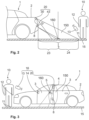
- FIG. 1 and 2 on the one hand and in the Figures 3 and 4 on the other hand, it is shown how an assembly module 20 according to the invention and an authentication system 16 according to the invention are used in a motor vehicle 1.
- the optical sensor system 30 of the assembly module 20 is arranged in the area of the tailgate 2, e.g. in a handle bar of the tailgate 2.
- the optical sensor system 30 generates a detection area 150 located outside the motor vehicle 1.
- the optical sensor system 30 permanently monitors the detection area 150 when the motor vehicle 1 is parked.
- the optical sensor system 30 detects that a user 10 is approaching the motor vehicle 1 and, if the user 10 is detected in the detection area 150, a signal is triggered to start an authentication check, the user does not have to take any action to initiate the authentication check.
- the user 10 therefore does not have to hold the ID transmitter 13 in one hand, but it is sufficient to carry the ID transmitter 13 in a pocket, for example. This is therefore a passive keyless entry check.
- an optical sensor system 30 monitors the detection area 150, it can be ensured that the signal for starting the authentication check is triggered before the user 10 reaches the motor vehicle 1. In this case, the authentication check will usually be completed before the user 10 has come closer to the motor vehicle 1 than an actuation area 160.
- the detection area 150 is limited to a predetermined spatial section, which, for example, only covers a few m 2 in a plan view. so that the signal for starting the authentication check is only rarely triggered. This means that the signal for starting the authentication check can be triggered in a timely and targeted manner.
- the detection area 150 has two legs 31, 32 that approach the optical sensor system 30.
- the detection area 150 also has a base 33 that delimits the detection area 21 on the side of the detection area 21 facing away from the optical sensor system 30.
- the detection area 21 ends at the base 33.
- the base 33 is straight.
- the two legs 31, 32 form an angle ⁇ .
- the tapering detection area 150 in the direction of the motor vehicle 1 makes it particularly easy to trigger the signal to start an authentication in a timely but still rare manner.
- the angle ⁇ is Figure 1 between 30° and 60°. This prevents a user 10 walking past the side of the motor vehicle 1 from entering the detection area 150.
- a length L which results from the distance of the base 33 to the optical sensor system 30, is 1.5 m.
- the length L and the angle ⁇ also result in x as the maximum distance of a point in the detection area 150 to the optical sensor system 30.
- the selected parameters limit the detection area 150 so that only a small amount of electrical power is required to monitor the detection area 150.
- the detection area 150 ends on a floor surface 15 on which the motor vehicle 1 is parked. As a result, the detection area 150 has an oblique truncated cone.
- a Figure 2 The angle ⁇ shown corresponds to an angle of the detection area 21 in a side view. In the present case, the angle ⁇ is chosen to be different from the angle ⁇ , so that the detection area 150 is elliptical.
- Another possibility of requiring only a small amount of electrical power is achieved by dividing the detection area 150 into a far zone 24 and a near zone 23, with the near zone 23 being closer to the sensor system 30 than the far zone 24. If the user 10 first enters the far zone 24, the optical sensor system 30 determines that an object is located in the far zone 24. The optical sensor system 30 also checks whether the object has a predetermined size. If the If the object has the specified size and the object moves into the near zone 23 of the detection area 150, a measurement of the distance of the object to an optical sensor 50 is also used in the near zone 23 to determine whether the object is approaching the optical sensor. If this is the case, the user 10 is recognized and a signal is triggered to start an authentication check between the ID transmitter 13 and an access control system 14 of the motor vehicle 1.
- the signal causes the access control system 14 to send a wake-up signal to the ID transmitter 13.
- the ID transmitter 13 then transmits an authentication code to the access control system 14.
- the access control system 14 compares the authentication code with a stored code. If the two codes match, the authentication is successful and an unlocking signal is triggered. This can be an unlocking signal for all doors of the motor vehicle 1 or just an unlocking signal for the tailgate 2.
- FIG. 3 and 4 A further embodiment is shown of how the assembly module 20 according to the invention is used.
- the mode of operation and function of the assembly module 20 in Figure 3 and 4 illustrated assembly module 20 of the mode of operation and function of the Figures 1 and 2
- the mounting module 20 is shown in the Figures 3 and 4 arranged in a B-pillar 4 of a vehicle side.
- the detection area 150 monitors an approach to a side door 3 of the motor vehicle 1.
- the working signal can be used to open the side door 3.
- the predefined movement for providing the working signal can be a predefined movement with a hand 12 of the user 10 in the area of a door handle 5.
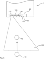
- FIG. 5 shows an embodiment of an assembly module 20 according to the invention, which is arranged on the rear of a motor vehicle 1.
- This assembly module 20 is equipped with a control device 100, which is part of an optical sensor system 30
- the control device 100 of this embodiment has a detection unit 110, a transmission unit 120 and a reception unit 130.
- the detection unit 110 is able to monitor the detection area 150 arranged behind the motor vehicle 1.
- the detection unit 110 can have a photo sensor, for example.
- Additional transmission units 120 for monitoring the detection area using artificial light are also possible in order to achieve a corresponding independence from the ambient lighting. Pulsed light flashes can also be used here.
- a transmission unit 120 is now additionally provided for emitting a laser light flash 122.
- the method steps to be carried out, which are made possible by an assembly module 20 according to the invention, are now described on the basis of the Figures 5 and 6 explained in more detail.
- FIG. 5 it can be seen how a user 10 enters the detection area 150, e.g. with a body part or completely. Since the detection area 150 is essentially continuously monitored by the detection unit 110, the optical sensor system 30 detects this movement of the user 10 with the help of the control device 100.
- the laser light flash 122 can now be emitted, preferably in a two-stage process, in order to obtain additional position information for the user 10.
- a correlation of the position of the user 10 with an actuation area 160 is now possible.
- the laser light flash 120 is preferably emitted with an emission direction 124 which overlaps with the actuation area 160 or illuminates it exactly with a homogeneous intensity distribution.
- the laser light flash 122 is at least partially reflected by the user 10.
- This reflected light of the laser light flash 122 can now be received and evaluated by a receiving unit 130.
- An evaluation is carried out in particular on the basis of the so-called TOF measurement, so that additional distance information is now available for the more precise positioning of the user 10 with correlation to the operating area 160.
- a signal can be triggered to carry out an action on the motor vehicle 1. This can be, for example, the opening of the tailgate or a side sliding door of the motor vehicle 1.
- FIG. 7 shows a schematic side view of another embodiment of an assembly module 20 according to the invention.
- This is equipped with an optical system 30, which again has a control device 100.
- the transmitting unit 120 is arranged above the detection unit 110, whereby the detection unit 110 also forms the receiving unit 130 in functional union.
- the control device 100 of this embodiment also has an evaluation unit 140.
- the fine position determination using the laser light flash 122 now makes it possible to monitor volume information regarding the detection area 150 or the actuation area 160.
- the movement of a foot 11 of a user 10 is shown here. If the foot 11 of the user 10 moves along the three positions shown, it first penetrates into the volume of the detection area 150. Only at this point in time is the pulsed laser light flashes 122 preferably emitted in the two-stage process along the emission direction 124 until it is recognized that the foot 11 of the user 10 is now in the volume of the actuation area 160.
- the signal for carrying out an action on the motor vehicle can now be triggered.
- an angle is formed between the horizontal H and the emission direction 124 of the laser light flash 122, which points downwards at an acute angle. This enables monitoring from top to bottom, so that the risk of injury to the human eye can preferably be completely excluded.
- FIG 8 an embodiment of an assembly module 20 according to the invention is shown, in which the transmitting unit 120 has a plurality of laser light sources 126. These individual laser light sources 126 are ring-shaped and evenly distributed around the receiving unit 130, which here also forms the detection unit 110. This leads to a particularly uniform light distribution in relation to the emission of the laser light flash 122. At the same time, the reduction in the distance between the transmitting unit 120 and the receiving unit 130 makes it possible to neglect the angle for the subsequent evaluation using the TOF method.
- Figure 9 shows a further embodiment of an assembly module 20 according to the invention.
- several laser light sources 126 are designed at a distance from one another for the transmission unit 120. This results in several, here schematically shown two, emission directions 124, which have a focal point B within the actuation area 160.
- the focal point B can also be designed as a volume element within the actuation area 160.
Landscapes
- Engineering & Computer Science (AREA)
- Physics & Mathematics (AREA)
- Radar, Positioning & Navigation (AREA)
- Remote Sensing (AREA)
- Computer Networks & Wireless Communication (AREA)
- General Physics & Mathematics (AREA)
- Electromagnetism (AREA)
- Mechanical Engineering (AREA)
- Acoustics & Sound (AREA)
- Optical Radar Systems And Details Thereof (AREA)
- Lock And Its Accessories (AREA)
- Power-Operated Mechanisms For Wings (AREA)
- Measurement Of Optical Distance (AREA)
- Measurement Of Velocity Or Position Using Acoustic Or Ultrasonic Waves (AREA)
Claims (15)
- Module de montage (20) pour un véhicule automobile (1), avec un système de capteur optique (30) qui est configuré pour,a) surveiller une zone de détection (150) située à l'extérieur du véhicule automobile (1) afin de déterminer la proximité d'un utilisateur (10),b) effectuer une mesure de distance par rapport à l'utilisateur (10) à l'intérieur de la zone de détection (150), etc) en cas de détection de l'utilisateur (10) dans une zone d'actionnement prédéfinie (160) à l'intérieur de la zone de détection (150), déclencher un signal pour l'exécution d'une action sur le véhicule automobile (1).
- Module de montage (20) selon la revendication 1,
caractérisé en ce quele système de capteur optique (30) est conçu pour exécuter l'étape b) au moyen d'une évaluation d'au moins deux images de la zone de détection (150) prises sous des angles différents,et/ou en ce que le système de capteur optique (30) est réalisé pour l'étape b) en exécutant les deux étapes partielles suivantes, à savoirb1) à émettre un flash de lumière laser (122) à l'intérieur de la zone de détection (150) ; etb2) détecter une réflexion du flash de lumière laser (122) par l'utilisateur (10). - Module de montage (20) selon l'une quelconque des revendications précédentes,
caractérisé en ce quele système de capteur optique (30) est conçu pour déclencher, en cas de reconnaissance de l'utilisateur (10) dans la zone de détection (150), un signal pour le démarrage d'un contrôle d'authentification entre un transmetteur ID (13) et un système de contrôle d'accès (14) du véhicule automobile (1) et que les étapes b) à d) ne sont exécutées que dans le cas d'un résultat d'authentification positif,et/ou en ce que le système de capteur optique (30) est conçu pour supprimer les étapes b) à c) lorsqu'aucun utilisateur (10) n'a été détecté dans la zone de détection (150). - Module de montage (20) selon l'une quelconque des revendications précédentes,
caractérisé en ce que
le système de capteur optique (30) présente une unité d'émission (120) pour l'émission d'un flash de lumière laser (122) avec une longueur d'onde dans la plage infrarouge, en particulier avec une longueur d'onde dans la plage de 905 nm +-environ 10 nm. - Module de montage (20) selon l'une quelconque des revendications précédentes, caractérisé en ce quele système de capteur optique (30) présente au moins un filtre optique, en particulier un filtre infrarouge, pour le filtrage optique d'un flash de lumière laser (122) émis et/ou de la réflexion du flash de lumière laser (122),et/ou en ce que le système de capteur optique (30) présente au moins un polariseur pour la polarisation d'un flash de lumière laser (122) émis et/ou de la réflexion du flash de lumière laser (122).
- Module de montage (20) selon l'une quelconque des revendications précédentes, caractérisé en ce quele système de capteur optique (30) présente une optique pour un élargissement de la répartition gaussienne de l'intensité d'un flash de lumière laser (122) émis, afin d'alimenter les bords de la zone de détection (150) avec une intensité suffisamment élevée,et/ou en ce que le système de capteur optique (30) présente une forme de construction cylindrique ou sensiblement cylindrique.
- Module de montage (20) selon l'une quelconque des revendications précédentes, caractérisé en ce que
le système de capteur optique (30) est conçu pour une superposition, en particulier une superposition complète, de la zone de détection (150) et/ou de la zone d'actionnement (160) avec un flash de lumière laser (122) émis. - Module de montage (20) selon l'une quelconque des revendications précédentes, caractérisé en ce quele système de capteur optique (30) présente un dispositif de contrôle (100) avec une unité d'émission (120) pour l'émission d'un flash de lumière laser (122), l'unité d'émission (120) présentant une orientation avec une direction d'émission (124) à angle aigu par rapport à l'horizontale (H), en particulier avec un angle supérieur à environ 30°,et/ou en ce que le système de capteur optique (30) présente un dispositif de contrôle (100) pour une évaluation de la différence de temps entre l'émission d'un signal d'émission, en particulier d'un flash de lumière laser (122) et la détection de la réflexion du signal d'émission, en particulier du flash de lumière laser (122) par l'utilisateur (10) sur la distance de l'utilisateur (10) par rapport au système de capteur optique (30).
- Module de montage (20) selon l'une quelconque des revendications précédentes, caractérisé en ce que
le signal pour l'exécution d'au moins une des actions suivantes est déclenché sur le véhicule automobile (1) :- Ouverture et/ou fermeture du hayon du véhicule automobile (1)- Ouverture et/ou fermeture d'une porte coulissante du véhicule automobile (1)- Ouverture et/ou fermeture d'une porte latérale du véhicule automobile (1)- Ouverture et/ou fermeture d'une fenêtre du véhicule automobile (1)- Ouverture et/ou fermeture du capot du véhicule automobile (1)- Ouverture et/ou fermeture du bouchon de réservoir du véhicule automobile (1)- Mise en marche et/ou arrêt d'un chauffage auxiliaire du véhicule automobile (1)- Mise en marche et/ou arrêt d'un chauffage de vitre du véhicule automobile (1)- L'activation et/ou la désactivation d'une fonction d'éclairage du véhicule automobile (1)- Rabattre et/ou déployer les rétroviseurs latéraux du véhicule automobile (1)- Mise en marche et/ou arrêt d'un système d'alarme du véhicule automobile (1)- Réglage d'un réglage spécifique à l'utilisateur dans le véhicule automobile (1), en particulier du réglage du siège du conducteur- Rentrer et/ou sortir un attelage de remorque. - Module de montage (20) selon l'une quelconque des revendications précédentes, caractérisé en ce que
le système de capteurs optiques (30) présente un dispositif de contrôle (100) avec une unité de détection (110) pour l'exécution de l'étape a), une unité d'émission (120) pour l'exécution de l'étape b) et une unité d'évaluation (140) pour l'exécution de l'étape c). - Module de montage (20) selon la revendication 10,
caractérisé en ce quel'unité d'émission (120) présente au moins une source de lumière laser (126) pour l'émission d'un flash de lumière laser (122) et une unité de réception (130) pour la réception d'une réflexion du flash de lumière laser (122) par l'utilisateur (10), en particulier pour l'émission pulsée d'une pluralité de flash de lumière laser (122) les uns derrière les autres,dans lequel, en particulier, la au moins une source de lumière laser (126) est disposée à côté de l'unité de réception (130). - Module de montage (20) selon l'une quelconque des revendications 10 à 11,
caractérisé en ce que
l'unité d'émission (120) est conçue pour émettre un flash de lumière laser (122) le long d'au moins deux directions d'émission (124) qui se rencontrent en un point focal (B) qui est disposé à l'intérieur de la zone de détection (150), en particulier à l'intérieur d'une zone d'actionnement (160). - Module de montage (20) selon l'une quelconque des revendications précédentes, caractérisé en ce que
l'émission d'un flash de lumière laser (122) a lieu dans la zone d'actionnement (160), qui est réalisée plus petite que la zone de détection (150) à l'intérieur de la zone de détection (150). - Procédé de déclenchement d'un signal pour la réalisation d'une action sur un véhicule automobile (1), le procédé étant notamment conçu pour fonctionner dans un module de montage (20) présentant les caractéristiques de l'une des revendications 1 à 13, comprenant les étapes suivantes :a) Surveiller une zone de détection (150) située à l'extérieur du véhicule automobile (1) afin de déterminer la proximité d'un utilisateur (10),b) Effectuer une mesure de distance par rapport à l'utilisateur (10) à l'intérieur de la zone de détection (150) ; etc) en cas de détection de l'utilisateur (10) dans une zone d'actionnement prédéfinie (160) à l'intérieur de la zone de détection (150), le déclenchement d'un signal pour l'exécution d'une action sur le véhicule automobile (1)caractérisé en ce que
le système de capteur optique (30) présente une unité d'émission (120) pour l'émission d'un flash de lumière laser (122) pour l'exécution de l'étape b) avec une longueur d'onde dans le domaine infrarouge avec une longueur d'onde dans la plage de 905nm +- environ 10nm. - Procédé selon la revendication 14,
caractérisé en ce que
pour l'étape b), les deux étapes partielles suivantes sont exécutées :b1) l'émission d'un flash de lumière laser (122) à l'intérieur de la zone de détection (150) ; etb2) la détection d'une réflexion du flash de lumière laser (122) par l'utilisateur (10).
Applications Claiming Priority (3)
| Application Number | Priority Date | Filing Date | Title |
|---|---|---|---|
| DE102014101206.2A DE102014101206A1 (de) | 2014-01-31 | 2014-01-31 | Montagemodul für ein Kraftfahrzeug |
| PCT/DE2015/100004 WO2015113550A1 (fr) | 2014-01-31 | 2015-01-07 | Module de montage pour véhicule à moteur |
| EP15705483.4A EP3099546B1 (fr) | 2014-01-31 | 2015-01-07 | Module de montage pour véhicule à moteur |
Related Parent Applications (1)
| Application Number | Title | Priority Date | Filing Date |
|---|---|---|---|
| EP15705483.4A Division EP3099546B1 (fr) | 2014-01-31 | 2015-01-07 | Module de montage pour véhicule à moteur |
Publications (2)
| Publication Number | Publication Date |
|---|---|
| EP3882089A1 EP3882089A1 (fr) | 2021-09-22 |
| EP3882089B1 true EP3882089B1 (fr) | 2024-08-28 |
Family
ID=52544237
Family Applications (2)
| Application Number | Title | Priority Date | Filing Date |
|---|---|---|---|
| EP15705483.4A Active EP3099546B1 (fr) | 2014-01-31 | 2015-01-07 | Module de montage pour véhicule à moteur |
| EP21165836.4A Active EP3882089B1 (fr) | 2014-01-31 | 2015-01-07 | Module de montage pour véhicule à moteur |
Family Applications Before (1)
| Application Number | Title | Priority Date | Filing Date |
|---|---|---|---|
| EP15705483.4A Active EP3099546B1 (fr) | 2014-01-31 | 2015-01-07 | Module de montage pour véhicule à moteur |
Country Status (6)
| Country | Link |
|---|---|
| US (1) | US10501052B2 (fr) |
| EP (2) | EP3099546B1 (fr) |
| JP (1) | JP6654146B2 (fr) |
| CN (1) | CN105980881A (fr) |
| DE (1) | DE102014101206A1 (fr) |
| WO (1) | WO2015113550A1 (fr) |
Families Citing this family (20)
| Publication number | Priority date | Publication date | Assignee | Title |
|---|---|---|---|---|
| DE102015115096A1 (de) * | 2015-09-08 | 2017-03-09 | Huf Hülsbeck & Fürst Gmbh & Co. Kg | Sensoranordnung zur optischen Erfassung von Bediengesten an Fahrzeugen |
| US20170083759A1 (en) * | 2015-09-21 | 2017-03-23 | Monster & Devices Home Sp. Zo. O. | Method and apparatus for gesture control of a device |
| KR101858698B1 (ko) * | 2016-01-04 | 2018-05-16 | 엘지전자 주식회사 | 차량용 디스플레이 장치 및 차량 |
| DE102016211494B4 (de) * | 2016-06-27 | 2020-10-01 | Ford Global Technologies, Llc | Steuerungseinrichtung für ein Kraftfahrzeug |
| US11180945B2 (en) * | 2016-10-04 | 2021-11-23 | U-Shin Ltd. | Door opening and closing device |
| CN110023580B (zh) * | 2016-11-30 | 2022-03-22 | 株式会社有信 | 车辆门开闭装置 |
| FR3064792B1 (fr) * | 2017-03-28 | 2019-03-29 | Continental Automotive France | Procede d’activation d’une fonction d’un vehicule |
| US11675064B2 (en) | 2017-05-31 | 2023-06-13 | Sharp Kabushiki Kaisha | Optical radar apparatus |
| DE102017115816A1 (de) * | 2017-07-13 | 2019-01-17 | Witte Automotive Gmbh | System mit Tür, Türschloss und Funkschlüssel |
| US10407970B2 (en) | 2017-07-31 | 2019-09-10 | Ford Global Technologies, Llc | Initiation of vehicle liftgate actuation |
| DE102018207683A1 (de) | 2018-05-17 | 2019-11-21 | Volkswagen Aktiengesellschaft | Abwehr eines Relayangriffs |
| WO2020115517A1 (fr) | 2018-12-03 | 2020-06-11 | 日産自動車株式会社 | Dispositif de commande de déplacement de véhicule et procédé de commande de déplacement de véhicule destinés au stationnement |
| DE102019209300A1 (de) * | 2019-06-26 | 2020-12-31 | Brose Fahrzeugteile Se & Co. Kommanditgesellschaft, Bamberg | Verstellsystem und Verfahren zum fremdkraftbetätigten Verstellen eines Fahrzeugverstellteils mithilfe einer optischen Erfassungseinrichtung |
| DE202019104826U1 (de) * | 2019-09-02 | 2019-09-26 | Tsubaki Kabelschlepp GmbH | Vorrichtung umfassend eine Energieführungskette und eine Gleitauflage |
| JP7215448B2 (ja) * | 2020-02-28 | 2023-01-31 | 株式会社デンソー | 検出器の姿勢・位置検出装置 |
| CN111591251B (zh) * | 2020-04-29 | 2021-09-21 | 惠州华阳通用电子有限公司 | 一种基于摄像模组的车辆燃油防盗预警方法、系统及车辆 |
| CN113086025B (zh) * | 2021-04-26 | 2022-04-15 | 长春捷翼汽车零部件有限公司 | 一种电动汽车的充电盖控制方法、设备及电动汽车 |
| CN114674294B (zh) * | 2022-03-16 | 2023-09-01 | 贵州师范学院 | 一种用于海洋测绘的防风装置及其使用方法 |
| US12578462B2 (en) | 2023-05-24 | 2026-03-17 | Ford Global Technologies, Llc | Systems and methods for detecting spatial availability around a vehicle |
| US12411234B2 (en) | 2023-05-24 | 2025-09-09 | Ford Global Technologies, Llc | Detection system for a vehicle |
Family Cites Families (20)
| Publication number | Priority date | Publication date | Assignee | Title |
|---|---|---|---|---|
| US7663502B2 (en) * | 1992-05-05 | 2010-02-16 | Intelligent Technologies International, Inc. | Asset system control arrangement and method |
| US5202742A (en) * | 1990-10-03 | 1993-04-13 | Aisin Seiki Kabushiki Kaisha | Laser radar for a vehicle lateral guidance system |
| JPH0743469A (ja) * | 1993-07-30 | 1995-02-14 | Omron Corp | 車々間通信システム |
| JP2006328932A (ja) | 2005-04-28 | 2006-12-07 | Denso Corp | 車両ドア制御システム |
| DE102005032402B3 (de) * | 2005-07-12 | 2006-09-28 | Daimlerchrysler Ag | Verfahren zum Nachweis einer Berechtigung zum Ver- oder Entriegeln eines Objekts sowie Sicherheitsvorrichtung |
| US8091280B2 (en) * | 2007-06-01 | 2012-01-10 | GM Global Technology Operations LLC | Arms full vehicle closure activation apparatus and method |
| JP2009014445A (ja) | 2007-07-03 | 2009-01-22 | Konica Minolta Holdings Inc | 測距装置 |
| WO2009014212A1 (fr) * | 2007-07-26 | 2009-01-29 | Omron Corporation | Procédé et dispositif de commande |
| DE102007050094A1 (de) | 2007-10-19 | 2009-04-23 | Witte-Velbert Gmbh & Co. Kg | Schließvorrichtung für ein Kraftfahrzeugschloss mit Vorfeld-Griffmuldenbeleuchtung |
| DE102008021989A1 (de) * | 2008-05-02 | 2008-12-18 | Daimler Ag | Vorrichtung zum Ver- und Entriegeln einer mittels eines elektronischen Zugangsberechtigungssystems gesicherten Fahrzeugtür für ein Fahrzeug |
| KR101483462B1 (ko) * | 2008-08-27 | 2015-01-16 | 삼성전자주식회사 | 깊이 영상 획득 장치 및 방법 |
| DE102009023594A1 (de) * | 2009-06-02 | 2010-12-09 | Volkswagen Ag | Verfahren und Vorrichtung zur Betätigung eines Schließelements eines Fahrzeugs |
| DE102010056171A1 (de) * | 2010-12-24 | 2012-06-28 | Volkswagen Ag | Verfahren zum automatischen Betätigen eines Schließelements eines Fahrzeugs sowie entsprechende Vorrichtung und Fahrzeug |
| JP2013007171A (ja) | 2011-06-22 | 2013-01-10 | Denso Corp | 車両ドア自動開閉装置 |
| JP5895201B2 (ja) * | 2011-07-29 | 2016-03-30 | パナソニックIpマネジメント株式会社 | 車両開閉体制御装置 |
| FR2979873B1 (fr) * | 2011-09-12 | 2013-10-04 | Valeo Securite Habitacle | Procede d'ouverture d'un ouvrant de vehicule automobile |
| DE102011115760A1 (de) * | 2011-10-12 | 2013-04-18 | Volkswagen Ag | Verfahren zur automatischen Betätigung eines Schließelements eines Fahrzeugs sowie entsprechende Vorrichtung und Fahrzeug |
| CN102658804A (zh) * | 2012-04-09 | 2012-09-12 | 上海齐汇通讯技术有限公司 | 一种车载智能终端系统及其实现方法 |
| US8542879B1 (en) * | 2012-06-26 | 2013-09-24 | Google Inc. | Facial recognition |
| CN202854922U (zh) | 2012-07-25 | 2013-04-03 | 北京盛世晶都科技有限公司 | 指纹认证自动遥控开启和车辆离开后自动关闭的停车地锁设备 |
-
2014
- 2014-01-31 DE DE102014101206.2A patent/DE102014101206A1/de not_active Withdrawn
-
2015
- 2015-01-07 JP JP2016567128A patent/JP6654146B2/ja not_active Expired - Fee Related
- 2015-01-07 WO PCT/DE2015/100004 patent/WO2015113550A1/fr not_active Ceased
- 2015-01-07 CN CN201580006697.6A patent/CN105980881A/zh active Pending
- 2015-01-07 EP EP15705483.4A patent/EP3099546B1/fr active Active
- 2015-01-07 EP EP21165836.4A patent/EP3882089B1/fr active Active
- 2015-01-07 US US15/115,472 patent/US10501052B2/en not_active Expired - Fee Related
Also Published As
| Publication number | Publication date |
|---|---|
| US20170166165A1 (en) | 2017-06-15 |
| JP6654146B2 (ja) | 2020-02-26 |
| EP3099546A1 (fr) | 2016-12-07 |
| WO2015113550A1 (fr) | 2015-08-06 |
| CN105980881A (zh) | 2016-09-28 |
| DE102014101206A1 (de) | 2015-08-06 |
| JP2017506756A (ja) | 2017-03-09 |
| US10501052B2 (en) | 2019-12-10 |
| EP3099546B1 (fr) | 2021-04-07 |
| EP3882089A1 (fr) | 2021-09-22 |
Similar Documents
| Publication | Publication Date | Title |
|---|---|---|
| EP3882089B1 (fr) | Module de montage pour véhicule à moteur | |
| EP3099545B1 (fr) | Module prêt au montage pour véhicule à moteur | |
| EP3744581B1 (fr) | Module prêt au montage pour véhicule à moteur | |
| EP3708757B1 (fr) | Module de montage pour un véhicule automobile doté d'un système de capteur optique et d'un actionnement d'urgence | |
| EP3099539B1 (fr) | Module prêt au montage pour véhicule à moteur | |
| EP3666607B1 (fr) | Procédé de production d'un signal de travail | |
| EP3099542B1 (fr) | Logo pour véhicule à moteur comportant un système capteur, et procédé correspondant | |
| EP3099547B1 (fr) | Module prêt au montage | |
| EP3099541B1 (fr) | Module de montage | |
| DE102017212221A1 (de) | Fernsteuerungsverfahren für ein Fahrerassistenzsystem, Fahrerassistenzsystem und damit versehenes Kraftfahrzeug | |
| WO2019115264A1 (fr) | Véhicule avec une caméra pour détecter une partie du corps d'un utilisateur et procédé de fonctionnement du véhicule | |
| EP3466772A1 (fr) | Module de montage doté d'un élément d'affichage |
Legal Events
| Date | Code | Title | Description |
|---|---|---|---|
| PUAI | Public reference made under article 153(3) epc to a published international application that has entered the european phase |
Free format text: ORIGINAL CODE: 0009012 |
|
| STAA | Information on the status of an ep patent application or granted ep patent |
Free format text: STATUS: THE APPLICATION HAS BEEN PUBLISHED |
|
| AC | Divisional application: reference to earlier application |
Ref document number: 3099546 Country of ref document: EP Kind code of ref document: P |
|
| AK | Designated contracting states |
Kind code of ref document: A1 Designated state(s): AL AT BE BG CH CY CZ DE DK EE ES FI FR GB GR HR HU IE IS IT LI LT LU LV MC MK MT NL NO PL PT RO RS SE SI SK SM TR |
|
| STAA | Information on the status of an ep patent application or granted ep patent |
Free format text: STATUS: REQUEST FOR EXAMINATION WAS MADE |
|
| 17P | Request for examination filed |
Effective date: 20220322 |
|
| RBV | Designated contracting states (corrected) |
Designated state(s): AL AT BE BG CH CY CZ DE DK EE ES FI FR GB GR HR HU IE IS IT LI LT LU LV MC MK MT NL NO PL PT RO RS SE SI SK SM TR |
|
| REG | Reference to a national code |
Ref country code: DE Ref legal event code: R079 Free format text: PREVIOUS MAIN CLASS: B60R0025240000 Ref country code: DE Ref legal event code: R079 Ref document number: 502015016939 Country of ref document: DE Free format text: PREVIOUS MAIN CLASS: B60R0025240000 Ipc: G01S0013080000 |
|
| RIC1 | Information provided on ipc code assigned before grant |
Ipc: G01S 17/10 20200101ALI20230922BHEP Ipc: G01S 15/08 20060101ALI20230922BHEP Ipc: G01S 13/08 20060101AFI20230922BHEP |
|
| GRAP | Despatch of communication of intention to grant a patent |
Free format text: ORIGINAL CODE: EPIDOSNIGR1 |
|
| STAA | Information on the status of an ep patent application or granted ep patent |
Free format text: STATUS: GRANT OF PATENT IS INTENDED |
|
| INTG | Intention to grant announced |
Effective date: 20231110 |
|
| GRAJ | Information related to disapproval of communication of intention to grant by the applicant or resumption of examination proceedings by the epo deleted |
Free format text: ORIGINAL CODE: EPIDOSDIGR1 |
|
| STAA | Information on the status of an ep patent application or granted ep patent |
Free format text: STATUS: REQUEST FOR EXAMINATION WAS MADE |
|
| GRAP | Despatch of communication of intention to grant a patent |
Free format text: ORIGINAL CODE: EPIDOSNIGR1 |
|
| STAA | Information on the status of an ep patent application or granted ep patent |
Free format text: STATUS: GRANT OF PATENT IS INTENDED |
|
| INTC | Intention to grant announced (deleted) | ||
| P01 | Opt-out of the competence of the unified patent court (upc) registered |
Effective date: 20240320 |
|
| INTG | Intention to grant announced |
Effective date: 20240411 |
|
| GRAS | Grant fee paid |
Free format text: ORIGINAL CODE: EPIDOSNIGR3 |
|
| GRAA | (expected) grant |
Free format text: ORIGINAL CODE: 0009210 |
|
| STAA | Information on the status of an ep patent application or granted ep patent |
Free format text: STATUS: THE PATENT HAS BEEN GRANTED |
|
| AC | Divisional application: reference to earlier application |
Ref document number: 3099546 Country of ref document: EP Kind code of ref document: P |
|
| AK | Designated contracting states |
Kind code of ref document: B1 Designated state(s): AL AT BE BG CH CY CZ DE DK EE ES FI FR GB GR HR HU IE IS IT LI LT LU LV MC MK MT NL NO PL PT RO RS SE SI SK SM TR |
|
| REG | Reference to a national code |
Ref country code: CH Ref legal event code: EP |
|
| REG | Reference to a national code |
Ref country code: DE Ref legal event code: R096 Ref document number: 502015016939 Country of ref document: DE |
|
| REG | Reference to a national code |
Ref country code: IE Ref legal event code: FG4D Free format text: LANGUAGE OF EP DOCUMENT: GERMAN |
|
| REG | Reference to a national code |
Ref country code: LT Ref legal event code: MG9D |
|
| PG25 | Lapsed in a contracting state [announced via postgrant information from national office to epo] |
Ref country code: NO Free format text: LAPSE BECAUSE OF FAILURE TO SUBMIT A TRANSLATION OF THE DESCRIPTION OR TO PAY THE FEE WITHIN THE PRESCRIBED TIME-LIMIT Effective date: 20241128 |
|
| PG25 | Lapsed in a contracting state [announced via postgrant information from national office to epo] |
Ref country code: NL Free format text: LAPSE BECAUSE OF FAILURE TO SUBMIT A TRANSLATION OF THE DESCRIPTION OR TO PAY THE FEE WITHIN THE PRESCRIBED TIME-LIMIT Effective date: 20240828 Ref country code: PL Free format text: LAPSE BECAUSE OF FAILURE TO SUBMIT A TRANSLATION OF THE DESCRIPTION OR TO PAY THE FEE WITHIN THE PRESCRIBED TIME-LIMIT Effective date: 20240828 Ref country code: GR Free format text: LAPSE BECAUSE OF FAILURE TO SUBMIT A TRANSLATION OF THE DESCRIPTION OR TO PAY THE FEE WITHIN THE PRESCRIBED TIME-LIMIT Effective date: 20241129 Ref country code: PT Free format text: LAPSE BECAUSE OF FAILURE TO SUBMIT A TRANSLATION OF THE DESCRIPTION OR TO PAY THE FEE WITHIN THE PRESCRIBED TIME-LIMIT Effective date: 20241230 Ref country code: FI Free format text: LAPSE BECAUSE OF FAILURE TO SUBMIT A TRANSLATION OF THE DESCRIPTION OR TO PAY THE FEE WITHIN THE PRESCRIBED TIME-LIMIT Effective date: 20240828 |
|
| PG25 | Lapsed in a contracting state [announced via postgrant information from national office to epo] |
Ref country code: BG Free format text: LAPSE BECAUSE OF FAILURE TO SUBMIT A TRANSLATION OF THE DESCRIPTION OR TO PAY THE FEE WITHIN THE PRESCRIBED TIME-LIMIT Effective date: 20240828 |
|
| PG25 | Lapsed in a contracting state [announced via postgrant information from national office to epo] |
Ref country code: LV Free format text: LAPSE BECAUSE OF FAILURE TO SUBMIT A TRANSLATION OF THE DESCRIPTION OR TO PAY THE FEE WITHIN THE PRESCRIBED TIME-LIMIT Effective date: 20240828 |
|
| REG | Reference to a national code |
Ref country code: NL Ref legal event code: MP Effective date: 20240828 |
|
| PG25 | Lapsed in a contracting state [announced via postgrant information from national office to epo] |
Ref country code: IS Free format text: LAPSE BECAUSE OF FAILURE TO SUBMIT A TRANSLATION OF THE DESCRIPTION OR TO PAY THE FEE WITHIN THE PRESCRIBED TIME-LIMIT Effective date: 20241228 |
|
| PG25 | Lapsed in a contracting state [announced via postgrant information from national office to epo] |
Ref country code: HR Free format text: LAPSE BECAUSE OF FAILURE TO SUBMIT A TRANSLATION OF THE DESCRIPTION OR TO PAY THE FEE WITHIN THE PRESCRIBED TIME-LIMIT Effective date: 20240828 |
|
| PG25 | Lapsed in a contracting state [announced via postgrant information from national office to epo] |
Ref country code: RS Free format text: LAPSE BECAUSE OF FAILURE TO SUBMIT A TRANSLATION OF THE DESCRIPTION OR TO PAY THE FEE WITHIN THE PRESCRIBED TIME-LIMIT Effective date: 20241128 Ref country code: ES Free format text: LAPSE BECAUSE OF FAILURE TO SUBMIT A TRANSLATION OF THE DESCRIPTION OR TO PAY THE FEE WITHIN THE PRESCRIBED TIME-LIMIT Effective date: 20240828 |
|
| PG25 | Lapsed in a contracting state [announced via postgrant information from national office to epo] |
Ref country code: RS Free format text: LAPSE BECAUSE OF FAILURE TO SUBMIT A TRANSLATION OF THE DESCRIPTION OR TO PAY THE FEE WITHIN THE PRESCRIBED TIME-LIMIT Effective date: 20241128 Ref country code: PT Free format text: LAPSE BECAUSE OF FAILURE TO SUBMIT A TRANSLATION OF THE DESCRIPTION OR TO PAY THE FEE WITHIN THE PRESCRIBED TIME-LIMIT Effective date: 20241230 Ref country code: PL Free format text: LAPSE BECAUSE OF FAILURE TO SUBMIT A TRANSLATION OF THE DESCRIPTION OR TO PAY THE FEE WITHIN THE PRESCRIBED TIME-LIMIT Effective date: 20240828 Ref country code: NO Free format text: LAPSE BECAUSE OF FAILURE TO SUBMIT A TRANSLATION OF THE DESCRIPTION OR TO PAY THE FEE WITHIN THE PRESCRIBED TIME-LIMIT Effective date: 20241128 Ref country code: NL Free format text: LAPSE BECAUSE OF FAILURE TO SUBMIT A TRANSLATION OF THE DESCRIPTION OR TO PAY THE FEE WITHIN THE PRESCRIBED TIME-LIMIT Effective date: 20240828 Ref country code: LV Free format text: LAPSE BECAUSE OF FAILURE TO SUBMIT A TRANSLATION OF THE DESCRIPTION OR TO PAY THE FEE WITHIN THE PRESCRIBED TIME-LIMIT Effective date: 20240828 Ref country code: IS Free format text: LAPSE BECAUSE OF FAILURE TO SUBMIT A TRANSLATION OF THE DESCRIPTION OR TO PAY THE FEE WITHIN THE PRESCRIBED TIME-LIMIT Effective date: 20241228 Ref country code: HR Free format text: LAPSE BECAUSE OF FAILURE TO SUBMIT A TRANSLATION OF THE DESCRIPTION OR TO PAY THE FEE WITHIN THE PRESCRIBED TIME-LIMIT Effective date: 20240828 Ref country code: GR Free format text: LAPSE BECAUSE OF FAILURE TO SUBMIT A TRANSLATION OF THE DESCRIPTION OR TO PAY THE FEE WITHIN THE PRESCRIBED TIME-LIMIT Effective date: 20241129 Ref country code: FI Free format text: LAPSE BECAUSE OF FAILURE TO SUBMIT A TRANSLATION OF THE DESCRIPTION OR TO PAY THE FEE WITHIN THE PRESCRIBED TIME-LIMIT Effective date: 20240828 Ref country code: ES Free format text: LAPSE BECAUSE OF FAILURE TO SUBMIT A TRANSLATION OF THE DESCRIPTION OR TO PAY THE FEE WITHIN THE PRESCRIBED TIME-LIMIT Effective date: 20240828 Ref country code: BG Free format text: LAPSE BECAUSE OF FAILURE TO SUBMIT A TRANSLATION OF THE DESCRIPTION OR TO PAY THE FEE WITHIN THE PRESCRIBED TIME-LIMIT Effective date: 20240828 |
|
| PGFP | Annual fee paid to national office [announced via postgrant information from national office to epo] |
Ref country code: DE Payment date: 20250131 Year of fee payment: 11 |
|
| PG25 | Lapsed in a contracting state [announced via postgrant information from national office to epo] |
Ref country code: DK Free format text: LAPSE BECAUSE OF FAILURE TO SUBMIT A TRANSLATION OF THE DESCRIPTION OR TO PAY THE FEE WITHIN THE PRESCRIBED TIME-LIMIT Effective date: 20240828 Ref country code: RO Free format text: LAPSE BECAUSE OF FAILURE TO SUBMIT A TRANSLATION OF THE DESCRIPTION OR TO PAY THE FEE WITHIN THE PRESCRIBED TIME-LIMIT Effective date: 20240828 Ref country code: SM Free format text: LAPSE BECAUSE OF FAILURE TO SUBMIT A TRANSLATION OF THE DESCRIPTION OR TO PAY THE FEE WITHIN THE PRESCRIBED TIME-LIMIT Effective date: 20240828 |
|
| PG25 | Lapsed in a contracting state [announced via postgrant information from national office to epo] |
Ref country code: EE Free format text: LAPSE BECAUSE OF FAILURE TO SUBMIT A TRANSLATION OF THE DESCRIPTION OR TO PAY THE FEE WITHIN THE PRESCRIBED TIME-LIMIT Effective date: 20240828 |
|
| PG25 | Lapsed in a contracting state [announced via postgrant information from national office to epo] |
Ref country code: CZ Free format text: LAPSE BECAUSE OF FAILURE TO SUBMIT A TRANSLATION OF THE DESCRIPTION OR TO PAY THE FEE WITHIN THE PRESCRIBED TIME-LIMIT Effective date: 20240828 |
|
| PG25 | Lapsed in a contracting state [announced via postgrant information from national office to epo] |
Ref country code: IT Free format text: LAPSE BECAUSE OF FAILURE TO SUBMIT A TRANSLATION OF THE DESCRIPTION OR TO PAY THE FEE WITHIN THE PRESCRIBED TIME-LIMIT Effective date: 20240828 Ref country code: SK Free format text: LAPSE BECAUSE OF FAILURE TO SUBMIT A TRANSLATION OF THE DESCRIPTION OR TO PAY THE FEE WITHIN THE PRESCRIBED TIME-LIMIT Effective date: 20240828 |
|
| REG | Reference to a national code |
Ref country code: DE Ref legal event code: R097 Ref document number: 502015016939 Country of ref document: DE |
|
| PLBE | No opposition filed within time limit |
Free format text: ORIGINAL CODE: 0009261 |
|
| STAA | Information on the status of an ep patent application or granted ep patent |
Free format text: STATUS: NO OPPOSITION FILED WITHIN TIME LIMIT |
|
| 26N | No opposition filed |
Effective date: 20250530 |
|
| REG | Reference to a national code |
Ref country code: CH Ref legal event code: PL |
|
| PG25 | Lapsed in a contracting state [announced via postgrant information from national office to epo] |
Ref country code: SE Free format text: LAPSE BECAUSE OF FAILURE TO SUBMIT A TRANSLATION OF THE DESCRIPTION OR TO PAY THE FEE WITHIN THE PRESCRIBED TIME-LIMIT Effective date: 20240828 |
|
| PG25 | Lapsed in a contracting state [announced via postgrant information from national office to epo] |
Ref country code: LU Free format text: LAPSE BECAUSE OF NON-PAYMENT OF DUE FEES Effective date: 20250107 Ref country code: MC Free format text: LAPSE BECAUSE OF FAILURE TO SUBMIT A TRANSLATION OF THE DESCRIPTION OR TO PAY THE FEE WITHIN THE PRESCRIBED TIME-LIMIT Effective date: 20240828 |
|
| GBPC | Gb: european patent ceased through non-payment of renewal fee |
Effective date: 20250107 |
|
| PG25 | Lapsed in a contracting state [announced via postgrant information from national office to epo] |
Ref country code: BE Free format text: LAPSE BECAUSE OF NON-PAYMENT OF DUE FEES Effective date: 20250131 Ref country code: GB Free format text: LAPSE BECAUSE OF NON-PAYMENT OF DUE FEES Effective date: 20250107 |
|
| PG25 | Lapsed in a contracting state [announced via postgrant information from national office to epo] |
Ref country code: FR Free format text: LAPSE BECAUSE OF NON-PAYMENT OF DUE FEES Effective date: 20250131 |
|
| PG25 | Lapsed in a contracting state [announced via postgrant information from national office to epo] |
Ref country code: CH Free format text: LAPSE BECAUSE OF NON-PAYMENT OF DUE FEES Effective date: 20250131 |
|
| REG | Reference to a national code |
Ref country code: BE Ref legal event code: MM Effective date: 20250131 |
|
| PG25 | Lapsed in a contracting state [announced via postgrant information from national office to epo] |
Ref country code: IE Free format text: LAPSE BECAUSE OF NON-PAYMENT OF DUE FEES Effective date: 20250107 |
|
| REG | Reference to a national code |
Ref country code: AT Ref legal event code: MM01 Ref document number: 1718552 Country of ref document: AT Kind code of ref document: T Effective date: 20250107 |
|
| PG25 | Lapsed in a contracting state [announced via postgrant information from national office to epo] |
Ref country code: AT Free format text: LAPSE BECAUSE OF NON-PAYMENT OF DUE FEES Effective date: 20250107 |