EP3882128A1 - Hubschrauber, hubschrauber-kit und zugehöriges rekonfigurationsverfahren - Google Patents
Hubschrauber, hubschrauber-kit und zugehöriges rekonfigurationsverfahren Download PDFInfo
- Publication number
- EP3882128A1 EP3882128A1 EP20164164.4A EP20164164A EP3882128A1 EP 3882128 A1 EP3882128 A1 EP 3882128A1 EP 20164164 A EP20164164 A EP 20164164A EP 3882128 A1 EP3882128 A1 EP 3882128A1
- Authority
- EP
- European Patent Office
- Prior art keywords
- axis
- helicopter
- aerodynamic
- chord
- leading edge
- Prior art date
- Legal status (The legal status is an assumption and is not a legal conclusion. Google has not performed a legal analysis and makes no representation as to the accuracy of the status listed.)
- Granted
Links
Images

Classifications
-
- B—PERFORMING OPERATIONS; TRANSPORTING
- B64—AIRCRAFT; AVIATION; COSMONAUTICS
- B64C—AEROPLANES; HELICOPTERS
- B64C27/00—Rotorcraft; Rotors peculiar thereto
- B64C27/04—Helicopters
-
- B—PERFORMING OPERATIONS; TRANSPORTING
- B64—AIRCRAFT; AVIATION; COSMONAUTICS
- B64C—AEROPLANES; HELICOPTERS
- B64C27/00—Rotorcraft; Rotors peculiar thereto
- B64C27/82—Rotorcraft; Rotors peculiar thereto characterised by the provision of an auxiliary rotor or fluid-jet device for counter-balancing lifting rotor torque or changing direction of rotorcraft
-
- B—PERFORMING OPERATIONS; TRANSPORTING
- B64—AIRCRAFT; AVIATION; COSMONAUTICS
- B64C—AEROPLANES; HELICOPTERS
- B64C39/00—Aircraft not otherwise provided for
- B64C39/06—Aircraft not otherwise provided for having disc- or ring-shaped wings
- B64C39/066—Aircraft not otherwise provided for having disc- or ring-shaped wings having channel wings
-
- B—PERFORMING OPERATIONS; TRANSPORTING
- B64—AIRCRAFT; AVIATION; COSMONAUTICS
- B64C—AEROPLANES; HELICOPTERS
- B64C5/00—Stabilising surfaces
- B64C5/02—Tailplanes
-
- B—PERFORMING OPERATIONS; TRANSPORTING
- B64—AIRCRAFT; AVIATION; COSMONAUTICS
- B64C—AEROPLANES; HELICOPTERS
- B64C3/00—Wings
- B64C3/10—Shape of wings
- B64C3/14—Aerofoil profile
- B64C2003/145—Aerofoil profile comprising 'Gurney' flaps
-
- B—PERFORMING OPERATIONS; TRANSPORTING
- B64—AIRCRAFT; AVIATION; COSMONAUTICS
- B64C—AEROPLANES; HELICOPTERS
- B64C27/00—Rotorcraft; Rotors peculiar thereto
- B64C27/82—Rotorcraft; Rotors peculiar thereto characterised by the provision of an auxiliary rotor or fluid-jet device for counter-balancing lifting rotor torque or changing direction of rotorcraft
- B64C2027/8263—Rotorcraft; Rotors peculiar thereto characterised by the provision of an auxiliary rotor or fluid-jet device for counter-balancing lifting rotor torque or changing direction of rotorcraft comprising in addition rudders, tails, fins, or the like
-
- B—PERFORMING OPERATIONS; TRANSPORTING
- B64—AIRCRAFT; AVIATION; COSMONAUTICS
- B64C—AEROPLANES; HELICOPTERS
- B64C27/00—Rotorcraft; Rotors peculiar thereto
- B64C27/82—Rotorcraft; Rotors peculiar thereto characterised by the provision of an auxiliary rotor or fluid-jet device for counter-balancing lifting rotor torque or changing direction of rotorcraft
- B64C2027/8263—Rotorcraft; Rotors peculiar thereto characterised by the provision of an auxiliary rotor or fluid-jet device for counter-balancing lifting rotor torque or changing direction of rotorcraft comprising in addition rudders, tails, fins, or the like
- B64C2027/8281—Rotorcraft; Rotors peculiar thereto characterised by the provision of an auxiliary rotor or fluid-jet device for counter-balancing lifting rotor torque or changing direction of rotorcraft comprising in addition rudders, tails, fins, or the like comprising horizontal tail planes
-
- Y—GENERAL TAGGING OF NEW TECHNOLOGICAL DEVELOPMENTS; GENERAL TAGGING OF CROSS-SECTIONAL TECHNOLOGIES SPANNING OVER SEVERAL SECTIONS OF THE IPC; TECHNICAL SUBJECTS COVERED BY FORMER USPC CROSS-REFERENCE ART COLLECTIONS [XRACs] AND DIGESTS
- Y02—TECHNOLOGIES OR APPLICATIONS FOR MITIGATION OR ADAPTATION AGAINST CLIMATE CHANGE
- Y02T—CLIMATE CHANGE MITIGATION TECHNOLOGIES RELATED TO TRANSPORTATION
- Y02T50/00—Aeronautics or air transport
- Y02T50/10—Drag reduction
Definitions
- the present invention relates to a helicopter, a helicopter kit and a helicopter reconfiguration method.
- Helicopters comprise, in a known manner, a fuselage, a main rotor projecting from the fuselage and rotatable about a first axis, and a tail rotor projecting from the fuselage and rotatable about a second axis transversal to the first axis.
- the main rotor is adapted to provide the lift necessary to sustain the helicopter in the air and to allow the forward/backward and lateral movement of the helicopter.
- the tail rotor is instead adapted to counter the rotation of the helicopter that would be caused by the reaction torque transmitted to the fuselage by operation of the main rotor, and to control the helicopter's yaw, i.e. the rotation about the first axis.
- Helicopters also comprise, in a known manner:
- the tailplane is configured as a wing profile that generates, when the helicopter is in forward flight, a first aerodynamic force, lift/negative lift, with a main component directed parallel to the first axis.
- This lift/negative lift is added to the lift generated by the main rotor and is effective in keeping the helicopter's attitude in stable conditions during high-speed forward flight, i.e. in ensuring that the helicopter is in a position of stable equilibrium with reference to the vertical direction and to the rotation about a third longitudinal axis of the helicopter.
- the third axis e parallel to a direction of extension of the fuselage oriented from a nose to the tail boom and is transversal to the first and second axes.
- this thrust causes a nose-up attitude on the helicopter, i.e. an attitude in which the nose of the fuselage is higher than the tail of the fuselage.
- This nose-up attitude must be continually corrected by the pilot acting on the cyclic pitch of the main rotor, i.e. by tilting the main rotor disc forwards so as to move the airflow away from the tailplane.
- the nose-up attitude in the landing phase causes visibility problems for the pilot, which can become even more problematic in cases of gusty wind, poor weather conditions or the presence of obstacles in the landing area.
- a large tailplane surface is required to generate an adequate value for the first aerodynamic force and therefore increase the longitudinal stability of the helicopter.
- a small tailplane surface is optimal at low speed to reduce the surface exposed to the downward airflow generated by the main rotor and the amount of the helicopter's consequent nose-up, and therefore improves the helicopter's visibility and manoeuvrability in particularly critical conditions, such as landing.
- tailplane configurations have been used on helicopters starting from the 1950s without achieving an optimal solution.
- tailplanes that are arranged on only one side of the fuselage and at different heights with respect to the tail boom, and symmetrical solutions with two stabilizers arranged at different heights and different longitudinal positions with respect to the fuselage.
- the object of the present invention is to produce a helicopter that enables satisfying at least one of the above-stated needs in a simple and inexpensive manner.
- this object is achieved by a helicopter according to claim 1.
- the present invention also relates to a kit for a helicopter according to claim 12.
- the present invention also relates to a method of reconfiguring a helicopter according to claim 15.
- reference numeral 1 indicates a helicopter made according to the dictates of the present invention.
- the helicopter 1 basically comprises a fuselage 2, a main rotor 3 arranged on top of the fuselage 2 and a tail rotor 5.
- the fuselage 2 comprises, at its opposite ends, a nose 6 and a tail boom 7.
- the axes X, Y, Z are integral with the helicopter 1 and are incident at the barycentre G (not indicated in the correct position in the accompanying figures for simplicity of representation) of the helicopter 1. It is also possible to define:
- the main rotor 3 is adapted to provide thrust with a main component parallel to the axis Z so as to enable sustaining the helicopter 1 in the air, the forward or backward movement parallel to the axis X and the lateral movement in both directions parallel to the axis Y.
- the tail rotor 5 is adapted to provide thrust with a main component parallel to the axis Y. This thrust generates torque about the axis Z in the opposite direction to the reaction torque acting on the fuselage 2 following operation of the main rotor 3, so as to control the yaw angle of the helicopter 1.
- the nose 6 and the tail boom 7 are opposite to each other along the longitudinal axis X of extension of the helicopter 1.
- the helicopter 1 also comprises:
- the fin 8 supports the tail rotor 5.
- the tailplane 9 is adapted to generate an aerodynamic force with a main component parallel to the axis Z, so as to longitudinally stabilize the helicopter 1 in forward flight, i.e. to make the attitude of the helicopter 1 stable with regard to rotation about the axis Y.
- the tailplane 9 comprises a pair of stabilizers 14 arranged on respective mutually opposite sides of the tail boom 7.
- the stabilizer 14 has a length parallel to the axis Y, a width parallel to the axis X and a thickness parallel to the axis Z.
- the stabilizer 14 comprises a load-bearing surface 11, which is configured to generate lift/negative lift with a main component parallel to the axis Z.
- the surface 11 of the stabilizer 14 is, in turn, delimitated by:
- the surface 11 also comprises a pair of end edges 12a, 12b opposite to each other and parallel to the axis Y.
- the end edge 12a of each surface 11 is fixed to the tail boom 7.
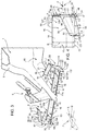
- the surface 11 has a chord B ( Figures 3 and 4 ) joining in a rectilinear way the leading edge 15 and the trailing edge 16 parallel to the axis X.
- the length of the chord B is constant.
- the stabilizer 14 comprises:
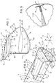
- the plane R is tilted with respect to the plane Q of an angle ⁇ ranging between 0 and 30 degrees, more specifically between 0 and 15 degrees ( Figure 5 ). It is therefore possible to desirably control the distance between the surfaces 11 and the appendages 21, minimizing the negative effects due to the mutual interference between the surfaces.
- the appendage 21 further extends from the plate 20 towards the fuselage of the helicopter 1.
- the appendage 21 further extends from the plate 20, at gradually increasing distances from the surface 11.
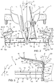
- the appendages 21 are mutually converging, from their respective plates 20 and on the side opposite to the respective surfaces 11 ( Figure 2 ).
- the chord C1 is shorter than the chord C2.
- the length of the chords C of the appendage 21 decreases from the chord C2 towards the chord C1 ( Figure 2 ).
- the appendage 21 further has a swept wing.
- the chord C1 has a section C3 projecting from the surface 11 in a plan view from above of the helicopter 1.
- the chord C2 has a section C4 projecting from the surface 11 in a plan view from above of the helicopter 1 ( Figure 4 ) .
- the length of each section C3, C4 parallel to the axis X ranges between -50% and 50% of chord B of the surface 11.
- the length of each section C3, C4 has a positive value when the section C3 projects from the leading edge 15 of the surface 11 towards the nose 6, in a plan view of the helicopter 1.
- the length of each section C3, C4 has a negative value when the section C3, C4 projects from the trailing edge 16 of the surface 11 towards the tail boom 7, in a plan view of the helicopter 1.
- the sections C3, C4 project from the leading edge 15 of the surface 11 towards the nose 6 of the helicopter 1.
- the section C4 is also shorter than the section C3.
- the appendage 21 has a negative swept wing and it is staggered towards the nose 6 with respect to the surface 11.
- an aerodynamic surface has a negative swept wing when it has a forward position (i.e. directed towards the nose 6) in a position corresponding to the quarter of the chord of the free end with respect to the same position corresponding to the quarter of the chord of the relative root portion (which will thus be rearward or directed to the opposite side of the fin 8) .
- leading edge 55 is directed towards the nose 6 and defines a first end edge that is more forward than the appendage 21, with reference to a normal forward direction of the helicopter 1.
- the trailing edge 56 is opposite to the leading edge 55 along the axis X, it is directed to the opposite side of the nose 6 and defines a second end edge that is more rearward than the appendage 21, with reference to a normal forward direction of the helicopter 1.
- the appendage 21 also comprises:
- the plate 20 is delimited parallel to the axis Z by an edge 30 connected to edge 12b of the surface 11 and by an edge 31 opposite to edge 30.
- the appendage 21 and the plate 20 are connected by a sharp edge.
- the edge 31 and the root end 80 are mutually coincident.
- the edges 30, 31 extend parallel to the axis X.
- the edge 31 is also arranged over the edge 30 and the appendage 21 is connected thereto. In particular, the edge 31 is farther to the fin 8 than the edge 30.
- the edges 30 are, therefore, interposed between the edges 31 along the axis Y.
- the plate 20 is also delimited by:
- the plate 20 also comprises a plurality of chords D that extend, each one in a rectilinear way, between the leading edge 55 and the trailing edge 56 ( Figure 6 ).
- the chords D1, D2 of the plate 20 at the edges 30, 31 define a plane S.
- the plane S is orthogonal to the plane R, as shown by way of examplein the enclosed Figure 5 .
- planes S define with the axis Z an angle ⁇ ranging between -30 degrees and 30 degrees, even more preferably ranging between -20 degrees and 20 degrees ( Figure 5 ). It is therefore possible to desirably control the joint between the plates 20 and the appendages 21, minimizing the negative effects due to the mutual interference between the surfaces.
- the angle ⁇ is oriented such to result positive when the planes S diverge between each other, with respect to the axis Z and such to result negative when the planes converge between each other with respect to the axis Z.
- the planes S diverge between each other with respect to the axis Z, proceeding from the surface 11 towards the relative appendages 21 ( Figure 5 ).
- the planes S also define an angle ⁇ with the axis X ranging between -15 degrees and 15 degrees, even more preferably ranging between -10 degrees and 10 degrees ( Figure 4 ).
- the angle ⁇ is oriented such to result positive/negative when the planes S converge/diverge between each other with respect to the axis X, and proceeding from the fin 8 towards the nose 6. In the case shown, the planes S also converge with each other with respect to the axis X, proceeding from the fin 8 towards the nose 6 ( Figure 4 )
- the plate 20 also comprises, proceeding from an edge 30 towards the edge 31 ( Figure 7 ):
- each surface 11 also comprises a pair of flaps 50, also known as Gurney flaps, applied to the respective opposite sides of the relative trailing edge 56, lying on the same plane and both orthogonal to the trailing edge 56 so as to form a T-shape.
- flaps 50 also known as Gurney flaps
- Each surface 11, comprises, in particular a zone 53 next to the plate 20 parallel to the axis Y and interposed between a section 106 of the leading edge 15 and a corresponding section 107 of the trailing edge 16 parallel to the axis X ( Figure 2 and 4 ).
- each zone 53 defines an extension of the relative surface 11.
- the leading edge, the trailing edge, the top surface and the bottom surface of each zone 53 are an extension of the leading edge 15, trailing edge 16, top surface 17 and bottom surface 18 of the relative surface 11.
- the wingspan 60 namely the extension parallel to the axis Y, of the zone 53 ranges between approximately 5% and 35% of the wingspan 61 of the appendage 21, preferably between 10% and 20%.
- the distance between the chords D1 and D2 measured on the plane S - namely the "height" of the plate 20 ranges between 10% and 100% of the length of the chord B of the surface 11.
- the chord E2 is arranged parallel to the chord E1.
- the length of the chord E is gradually decreasing from the length of the chord E1 to the length of the chord E2.
- the distance between the chords E1 and E2 measured on the plane T - namely the height of the element 100 ranges between 10% and 100% of the length of the chord B of the surface 11.
- the length of the chord C2 ranges between 20% and 100% of the length of the chord B of the surface 11.
- the length of the chord C1 ranges between 20% and 100% of the length of the chord C2.
- the stabilizer 14 comprises a joint portion 120 interposed between the root end 80 of the appendage 21 and the edge 31 of the plate 20.
- the portion 120 extends, from the edge 31 towards the end 80, at a distance gradually increasing from the surface 11 and gradually decreasing from the fin 8.
- the length of the chord of the portion 120 gradually reduces from value D2 to value C2.
- the plates 20, the appendage 21, the zone 53 of the stabilizer 14 and the Gurney flaps 50 form a reconfiguration kit 85 ( Figure 2 ) for a stabilizer of a helicopter comprising the only surface 11.
- Operation of the helicopter 1 is described starting from low-speed forward flight or hovering conditions typical, for example, of the phases of take-off/landing.
- the appendages 21 arranged above the surfaces 11 obstruct the passage of this wash towards the surfaces 11, which are therefore subjected to a particularly low or null downward thrust due to the wash of the main rotor 3.
- the small overall extension of the appendages 21 enable further reducing the downward thrust that this wash exerts on the tailplane 9.
- the tailplane 9 generates aerodynamic thrust with a component parallel to the axis Z that enables keeping the helicopter 1 in stable equilibrium with respect to translation along the axis Z and rotation about the axis Y.
- the kit 85 is used to reconfigure a helicopter equipped with stabilizers that each comprise only the surface 11 without the relative zone 53.
- the zones 53 of the kit 85 are placed side by side to the relative surfaces 11 along the axis Y and connected thereto, so as to define relative extensions thereof and such that the relative appendages 21 are faced at a distance from the respective surfaces 11 and have the relative free ends 81 spaced from the tail boom 7/fin 8 along the axis Y.
- the appendages 21 of the stabilizers 14 generate an aerodynamic force, and also have free respective ends 81 spaced from the tail boom 7/fin 8 and the relative planes R tilted with respect to Q of the angle ⁇ .
- the stabilizers 14 are less heavy and less bulky than the stabilizers of the known solutions described in the introductory part of this description, with obvious advantages for the helicopter 1.
- the tailplane 9 enables a high degree of longitudinal stability of the helicopter 1 with reduced weight.
- the surfaces 11 are in the turbulent wash of the appendages 21.
- the downward thrust generated by the wash of the main rotor 3 on the tailplane 9 is thus reduced with respect to traditional solutions, reducing the tendency of the helicopter 1 to assume a nose-up attitude and improving the pilot's comfort and visibility during landing operations.
- the Applicant has observed that due to the fact that the appendages 21 have respective free ends 81 it is possible to further reduce the thrust downwards generated by the flow of the rotor 3 on the tailplane 9.
- the presence of the free ends 81 also allows to substantially reduce the overall induced resistance of the tailplane 9, consequently improving the aerodynamic efficiency thereof.
- the appendages 21 enable increasing the value of the aerodynamic forces generated by the tailplane 9 at the angles of attack typical of operation of the helicopter 1.
- the planes S define with the axis Z the angle ⁇ ranging between -30 degrees and +30 degrees, preferably ranging between -20 degrees and +20 degrees. It is therefore possible to desirably control the joint between the plates 20 and the appendages 21, minimizing the negative effects due to the mutual interference between the surfaces.
- the planes S also define with the axis X an angle ⁇ ranging between -15 degrees and 15 degrees, preferably ranging between -10 degrees and 10 degrees. It is therefore possible to modify the pressure field generated on elements 11, 20 and 21, in particular a local depression, and obtain a desired efficiency value that is greater than the entire tailplane 9.
- the sections C3 and C4 of each appendage 21 have a length parallel to the axis X ranging between -50% and 50% of the chord B of the relative surface 11. Due to that, the appendages 21 have a swept wing and are staggered with respect to the relative surfaces 11 along the axis X.
- kits 85 enable reconfiguring a helicopter with a traditional tailplane by simply fixing the zone 53 to the surface 11 so as to define its extension and to arrange the appendage 21 facing the surface 11 and spaced from the tail boom 7/fin 8.
- the T-shaped flaps 50 are particularly advantageous when incorporated in the kit 85.
- the T-shape allows increasing the lift generated by the stabilizers 14 without altering the attitude of the helicopter 1 with respect to a condition in which the kit 85 was not present.
- each stabilizer 14 might comprise at least a first additional appendage 21 arranged on the side of the top surface 17 of the surface 11 along the axis Z and spaced from the fin 8 along the axis Y and at least a second additional appendage 21 arranged on the side of the bottom surface 18 of the surface 11 along the axis Z and spaced from the tail boom 7 along the axis Y .
- the first additional appendages 21 might be more than one and/or the second additional appendages 21 may be more than one.
- each stabilizer 14 might comprise at least two first additional appendages 21 arranged on the side of the top surface 17 of the surface 11, spaced from the fin 8 and staggered from the axis X.
- each stabilizer 14 might comprise at least two second additional appendages 21 arranged on the side of the bottom surface 18 of the surface 11, spaced from the fin 8 and staggered along the axis X.
- the first and second additional appendages 21 allow to increase the aerodynamic force generated by the tailplane 9 and, therefore, the stabilization effect at high-speed, further increasing the shielding effect of the surface 11 against the downward flow generated by the rotor 3.
- the length of sections C3, C4 of each appendage 21 might be the same. In that case, each appendage 21 would simply be staggered with respect to the relative surface 11 towards the nose 6 or towards the tail boom 7, without any geometric swept wing.
- chords B, C, D, E of the surface 11, appendage 21, plate 20 and element 100 may be bent namely obtained by the rotation of the relative planes R, S, T of a constant angle.
- the planes R; S; T would identify the planes defined by the chords C1, C2; D1, D2; E1, E2 with no bend.
Landscapes
- Engineering & Computer Science (AREA)
- Aviation & Aerospace Engineering (AREA)
- Mechanical Engineering (AREA)
- Toys (AREA)
- Agricultural Chemicals And Associated Chemicals (AREA)
- Medicines Containing Material From Animals Or Micro-Organisms (AREA)
- Automatic Assembly (AREA)
Priority Applications (9)
| Application Number | Priority Date | Filing Date | Title |
|---|---|---|---|
| EP20164164.4A EP3882128B1 (de) | 2020-03-19 | 2020-03-19 | Hubschrauber, hubschrauber-kit und zugehöriges rekonfigurationsverfahren |
| KR1020227034481A KR20230002357A (ko) | 2020-03-19 | 2021-03-19 | 헬리콥터, 헬리콥터 키트, 및 관련 재구성 방법 |
| JP2022556213A JP7674379B2 (ja) | 2020-03-19 | 2021-03-19 | ヘリコプタ、ヘリコプタキット及び関連する再構成方法 |
| BR112022018595-2A BR112022018595B1 (pt) | 2020-03-19 | 2021-03-19 | Helicóptero, e, kit e método de atualização para um helicóptero |
| CN202180021957.2A CN115298091B (zh) | 2020-03-19 | 2021-03-19 | 直升机、直升机套件及相关联的重新配置方法 |
| CA3171916A CA3171916A1 (en) | 2020-03-19 | 2021-03-19 | Helicopter, helicopter kit and associated reconfiguration method |
| PCT/IB2021/052324 WO2021186411A1 (en) | 2020-03-19 | 2021-03-19 | Helicopter, helicopter kit and associated reconfiguration method |
| US17/911,544 US12466542B2 (en) | 2020-03-19 | 2021-03-19 | Helicopter, helicopter kit and associated reconfiguration method |
| IL296485A IL296485B2 (en) | 2020-03-19 | 2021-03-19 | Helicopter, helicopter kit and related method for reconfiguration |
Applications Claiming Priority (1)
| Application Number | Priority Date | Filing Date | Title |
|---|---|---|---|
| EP20164164.4A EP3882128B1 (de) | 2020-03-19 | 2020-03-19 | Hubschrauber, hubschrauber-kit und zugehöriges rekonfigurationsverfahren |
Publications (2)
| Publication Number | Publication Date |
|---|---|
| EP3882128A1 true EP3882128A1 (de) | 2021-09-22 |
| EP3882128B1 EP3882128B1 (de) | 2022-08-31 |
Family
ID=70740395
Family Applications (1)
| Application Number | Title | Priority Date | Filing Date |
|---|---|---|---|
| EP20164164.4A Active EP3882128B1 (de) | 2020-03-19 | 2020-03-19 | Hubschrauber, hubschrauber-kit und zugehöriges rekonfigurationsverfahren |
Country Status (8)
| Country | Link |
|---|---|
| US (1) | US12466542B2 (de) |
| EP (1) | EP3882128B1 (de) |
| JP (1) | JP7674379B2 (de) |
| KR (1) | KR20230002357A (de) |
| CN (1) | CN115298091B (de) |
| CA (1) | CA3171916A1 (de) |
| IL (1) | IL296485B2 (de) |
| WO (1) | WO2021186411A1 (de) |
Families Citing this family (1)
| Publication number | Priority date | Publication date | Assignee | Title |
|---|---|---|---|---|
| JP2024106285A (ja) * | 2023-01-26 | 2024-08-07 | 株式会社Subaru | ヘリコプタ、ヘリコプタの垂直尾翼、ヘリコプタの垂直尾翼の改修方法及びヘリコプタのテールロータによるアンチトルクの向上方法 |
Citations (2)
| Publication number | Priority date | Publication date | Assignee | Title |
|---|---|---|---|---|
| US8985500B2 (en) | 2010-07-20 | 2015-03-24 | Airbus Helicopters | Method of minimizing the attitude hump phenomenon and a rotary wing aircraft provided with stabilizer means therefor |
| EP2878536A1 (de) * | 2013-11-29 | 2015-06-03 | AIRBUS HELICOPTERS DEUTSCHLAND GmbH | Erweiterter Steigungsstabilisator |
Family Cites Families (21)
| Publication number | Priority date | Publication date | Assignee | Title |
|---|---|---|---|---|
| US2194596A (en) * | 1936-04-24 | 1940-03-26 | Henter Mathias | Airplane |
| JPH04146893A (ja) * | 1990-10-08 | 1992-05-20 | Mitsubishi Heavy Ind Ltd | ヘリコプタ |
| FR2689854B1 (fr) * | 1992-04-14 | 1994-07-01 | Eurocopter France | Helicoptere monorotor a systeme anticouple mixte et procede pour contrecarrer le couple induit par ce monorotor. |
| US6474604B1 (en) * | 1999-04-12 | 2002-11-05 | Jerry E. Carlow | Mobius-like joining structure for fluid dynamic foils |
| GB0518755D0 (en) * | 2005-09-14 | 2005-10-19 | Airbus Uk Ltd | Wing tip device |
| US7644892B1 (en) * | 2006-07-06 | 2010-01-12 | Alford Jr Lionel D | Blended winglet |
| US9545993B2 (en) * | 2007-01-12 | 2017-01-17 | John William McGinnis | Aircraft stability and efficient control through induced drag reduction |
| US8657226B1 (en) * | 2007-01-12 | 2014-02-25 | John William McGinnis | Efficient control and stall prevention in advanced configuration aircraft |
| US20110024573A1 (en) * | 2009-05-06 | 2011-02-03 | Quiet Wing Technologies, Inc. | Extended winglet with load balancing characteristics |
| US8382041B1 (en) * | 2010-08-04 | 2013-02-26 | The United States Of America As Represented By The Secretary Of The Air Force | Rakelet |
| US8882024B1 (en) * | 2013-06-24 | 2014-11-11 | Bell Helicopter Textron Inc. | Rotorcraft anti-torque rotor and rudder system |
| USD736140S1 (en) * | 2013-08-23 | 2015-08-11 | Moller International, Inc. | Vertical takeoff and landing vehicle |
| GB2528231A (en) * | 2014-04-24 | 2016-01-20 | Airbus Operations Ltd | An aircraft with a foldable wing tip device |
| DE102014112827B3 (de) * | 2014-09-05 | 2016-02-11 | Airbus Defence and Space GmbH | Luftfahrzeug mit C-förmigen Tragflächen und bewegbaren Topflächen |
| US10611460B2 (en) * | 2017-05-11 | 2020-04-07 | Bell Helicopter Textron Inc. | Aircraft vertical stabilizer design |
| CN108045554A (zh) * | 2017-11-29 | 2018-05-18 | 中国航空工业集团公司西安飞机设计研究所 | 一种涡扇双垂尾预警机 |
| US11072422B2 (en) * | 2018-06-09 | 2021-07-27 | Textron Innovations Inc. | Counter torque device |
| FR3082505B1 (fr) * | 2018-06-14 | 2021-01-15 | Airbus Helicopters | Profils aerodynamiques a efficacite stabilisatrice amelioree pour empennages et derives |
| US11572155B2 (en) * | 2019-10-28 | 2023-02-07 | Textron Innovations Inc. | Rotorcraft having propeller generated power during autorotations |
| US11554860B1 (en) * | 2020-06-23 | 2023-01-17 | Piasecki Aircraft Corporation | Apparatus, system and method for a convertible thruster for a compound aircraft |
| USD976799S1 (en) * | 2020-11-17 | 2023-01-31 | Darold B Cummings | Aircraft |
-
2020
- 2020-03-19 EP EP20164164.4A patent/EP3882128B1/de active Active
-
2021
- 2021-03-19 IL IL296485A patent/IL296485B2/en unknown
- 2021-03-19 JP JP2022556213A patent/JP7674379B2/ja active Active
- 2021-03-19 US US17/911,544 patent/US12466542B2/en active Active
- 2021-03-19 WO PCT/IB2021/052324 patent/WO2021186411A1/en not_active Ceased
- 2021-03-19 CA CA3171916A patent/CA3171916A1/en active Pending
- 2021-03-19 CN CN202180021957.2A patent/CN115298091B/zh active Active
- 2021-03-19 KR KR1020227034481A patent/KR20230002357A/ko active Pending
Patent Citations (2)
| Publication number | Priority date | Publication date | Assignee | Title |
|---|---|---|---|---|
| US8985500B2 (en) | 2010-07-20 | 2015-03-24 | Airbus Helicopters | Method of minimizing the attitude hump phenomenon and a rotary wing aircraft provided with stabilizer means therefor |
| EP2878536A1 (de) * | 2013-11-29 | 2015-06-03 | AIRBUS HELICOPTERS DEUTSCHLAND GmbH | Erweiterter Steigungsstabilisator |
Also Published As
| Publication number | Publication date |
|---|---|
| CA3171916A1 (en) | 2021-09-23 |
| KR20230002357A (ko) | 2023-01-05 |
| US12466542B2 (en) | 2025-11-11 |
| JP2023518770A (ja) | 2023-05-08 |
| BR112022018595A2 (pt) | 2022-12-06 |
| WO2021186411A1 (en) | 2021-09-23 |
| EP3882128B1 (de) | 2022-08-31 |
| CN115298091B (zh) | 2026-02-27 |
| IL296485B2 (en) | 2025-09-01 |
| US20230174219A1 (en) | 2023-06-08 |
| IL296485A (en) | 2022-11-01 |
| JP7674379B2 (ja) | 2025-05-09 |
| IL296485B1 (en) | 2025-05-01 |
| CN115298091A (zh) | 2022-11-04 |
Similar Documents
| Publication | Publication Date | Title |
|---|---|---|
| US6827314B2 (en) | Aircraft with active control of the warping of its wings | |
| US8651431B1 (en) | Aircraft with movable winglets and method of control | |
| EP2878536B1 (de) | Erweiterter Steigungsstabilisator | |
| US5108044A (en) | Shroud-fin integration shelf for a helicopter empennage structure | |
| JP2013212834A (ja) | 性能向上型ウイングレットシステムおよびその方法 | |
| US12157562B2 (en) | Helicopter, helicopter kit and associated reconfiguration method | |
| CN111846199A (zh) | 具有稳定翼的旋翼飞行器 | |
| US11554849B2 (en) | Tailless aircraft | |
| US12466542B2 (en) | Helicopter, helicopter kit and associated reconfiguration method | |
| JP7178699B2 (ja) | 凧 | |
| BR112022018595B1 (pt) | Helicóptero, e, kit e método de atualização para um helicóptero | |
| KR102798621B1 (ko) | 항공기 및 관련 제작 방법 | |
| US20260116526A1 (en) | Rotary-Wing Aircraft Provided with at least one Multi-Plane Pitch Stabilizer | |
| CN112758305B (zh) | 变构型飞行器 | |
| RU2743306C1 (ru) | Винтокрылый летательный аппарат с крылом-стабилизатором | |
| CN112660364B (zh) | 一种自动调整攻角大小的机翼 | |
| CN213677118U (zh) | 一种通航飞机多片式尾翼 |
Legal Events
| Date | Code | Title | Description |
|---|---|---|---|
| PUAI | Public reference made under article 153(3) epc to a published international application that has entered the european phase |
Free format text: ORIGINAL CODE: 0009012 |
|
| STAA | Information on the status of an ep patent application or granted ep patent |
Free format text: STATUS: REQUEST FOR EXAMINATION WAS MADE |
|
| 17P | Request for examination filed |
Effective date: 20200925 |
|
| AK | Designated contracting states |
Kind code of ref document: A1 Designated state(s): AL AT BE BG CH CY CZ DE DK EE ES FI FR GB GR HR HU IE IS IT LI LT LU LV MC MK MT NL NO PL PT RO RS SE SI SK SM TR |
|
| GRAP | Despatch of communication of intention to grant a patent |
Free format text: ORIGINAL CODE: EPIDOSNIGR1 |
|
| STAA | Information on the status of an ep patent application or granted ep patent |
Free format text: STATUS: GRANT OF PATENT IS INTENDED |
|
| RIC1 | Information provided on ipc code assigned before grant |
Ipc: B64C 3/14 20060101ALN20211014BHEP Ipc: B64C 39/06 20060101ALI20211014BHEP Ipc: B64C 27/82 20060101ALI20211014BHEP Ipc: B64C 27/04 20060101ALI20211014BHEP Ipc: B64C 5/02 20060101AFI20211014BHEP |
|
| INTG | Intention to grant announced |
Effective date: 20211103 |
|
| RIN1 | Information on inventor provided before grant (corrected) |
Inventor name: BIANCO MENGOTTI, RICCARDO Inventor name: SCANDROGLIO, ALESSANDRO Inventor name: MEDICI, LUCA Inventor name: CAMPANARDI, GABRIELE Inventor name: MELONE, STEFANO |
|
| GRAJ | Information related to disapproval of communication of intention to grant by the applicant or resumption of examination proceedings by the epo deleted |
Free format text: ORIGINAL CODE: EPIDOSDIGR1 |
|
| STAA | Information on the status of an ep patent application or granted ep patent |
Free format text: STATUS: REQUEST FOR EXAMINATION WAS MADE |
|
| GRAP | Despatch of communication of intention to grant a patent |
Free format text: ORIGINAL CODE: EPIDOSNIGR1 |
|
| STAA | Information on the status of an ep patent application or granted ep patent |
Free format text: STATUS: GRANT OF PATENT IS INTENDED |
|
| INTC | Intention to grant announced (deleted) | ||
| RIC1 | Information provided on ipc code assigned before grant |
Ipc: B64C 3/14 20060101ALN20220310BHEP Ipc: B64C 39/06 20060101ALI20220310BHEP Ipc: B64C 27/82 20060101ALI20220310BHEP Ipc: B64C 27/04 20060101ALI20220310BHEP Ipc: B64C 5/02 20060101AFI20220310BHEP |
|
| INTG | Intention to grant announced |
Effective date: 20220329 |
|
| GRAS | Grant fee paid |
Free format text: ORIGINAL CODE: EPIDOSNIGR3 |
|
| GRAA | (expected) grant |
Free format text: ORIGINAL CODE: 0009210 |
|
| STAA | Information on the status of an ep patent application or granted ep patent |
Free format text: STATUS: THE PATENT HAS BEEN GRANTED |
|
| AK | Designated contracting states |
Kind code of ref document: B1 Designated state(s): AL AT BE BG CH CY CZ DE DK EE ES FI FR GB GR HR HU IE IS IT LI LT LU LV MC MK MT NL NO PL PT RO RS SE SI SK SM TR |
|
| REG | Reference to a national code |
Ref country code: CH Ref legal event code: EP Ref country code: GB Ref legal event code: FG4D |
|
| REG | Reference to a national code |
Ref country code: AT Ref legal event code: REF Ref document number: 1515124 Country of ref document: AT Kind code of ref document: T Effective date: 20220915 Ref country code: DE Ref legal event code: R096 Ref document number: 602020004765 Country of ref document: DE |
|
| REG | Reference to a national code |
Ref country code: IE Ref legal event code: FG4D |
|
| REG | Reference to a national code |
Ref country code: LT Ref legal event code: MG9D |
|
| REG | Reference to a national code |
Ref country code: NL Ref legal event code: MP Effective date: 20220831 |
|
| PG25 | Lapsed in a contracting state [announced via postgrant information from national office to epo] |
Ref country code: SE Free format text: LAPSE BECAUSE OF FAILURE TO SUBMIT A TRANSLATION OF THE DESCRIPTION OR TO PAY THE FEE WITHIN THE PRESCRIBED TIME-LIMIT Effective date: 20220831 Ref country code: RS Free format text: LAPSE BECAUSE OF FAILURE TO SUBMIT A TRANSLATION OF THE DESCRIPTION OR TO PAY THE FEE WITHIN THE PRESCRIBED TIME-LIMIT Effective date: 20220831 Ref country code: NO Free format text: LAPSE BECAUSE OF FAILURE TO SUBMIT A TRANSLATION OF THE DESCRIPTION OR TO PAY THE FEE WITHIN THE PRESCRIBED TIME-LIMIT Effective date: 20221130 Ref country code: LV Free format text: LAPSE BECAUSE OF FAILURE TO SUBMIT A TRANSLATION OF THE DESCRIPTION OR TO PAY THE FEE WITHIN THE PRESCRIBED TIME-LIMIT Effective date: 20220831 Ref country code: LT Free format text: LAPSE BECAUSE OF FAILURE TO SUBMIT A TRANSLATION OF THE DESCRIPTION OR TO PAY THE FEE WITHIN THE PRESCRIBED TIME-LIMIT Effective date: 20220831 Ref country code: FI Free format text: LAPSE BECAUSE OF FAILURE TO SUBMIT A TRANSLATION OF THE DESCRIPTION OR TO PAY THE FEE WITHIN THE PRESCRIBED TIME-LIMIT Effective date: 20220831 |
|
| REG | Reference to a national code |
Ref country code: AT Ref legal event code: MK05 Ref document number: 1515124 Country of ref document: AT Kind code of ref document: T Effective date: 20220831 |
|
| PG25 | Lapsed in a contracting state [announced via postgrant information from national office to epo] |
Ref country code: PL Free format text: LAPSE BECAUSE OF FAILURE TO SUBMIT A TRANSLATION OF THE DESCRIPTION OR TO PAY THE FEE WITHIN THE PRESCRIBED TIME-LIMIT Effective date: 20220831 Ref country code: IS Free format text: LAPSE BECAUSE OF FAILURE TO SUBMIT A TRANSLATION OF THE DESCRIPTION OR TO PAY THE FEE WITHIN THE PRESCRIBED TIME-LIMIT Effective date: 20221231 Ref country code: HR Free format text: LAPSE BECAUSE OF FAILURE TO SUBMIT A TRANSLATION OF THE DESCRIPTION OR TO PAY THE FEE WITHIN THE PRESCRIBED TIME-LIMIT Effective date: 20220831 Ref country code: GR Free format text: LAPSE BECAUSE OF FAILURE TO SUBMIT A TRANSLATION OF THE DESCRIPTION OR TO PAY THE FEE WITHIN THE PRESCRIBED TIME-LIMIT Effective date: 20221201 |
|
| PG25 | Lapsed in a contracting state [announced via postgrant information from national office to epo] |
Ref country code: SM Free format text: LAPSE BECAUSE OF FAILURE TO SUBMIT A TRANSLATION OF THE DESCRIPTION OR TO PAY THE FEE WITHIN THE PRESCRIBED TIME-LIMIT Effective date: 20220831 Ref country code: RO Free format text: LAPSE BECAUSE OF FAILURE TO SUBMIT A TRANSLATION OF THE DESCRIPTION OR TO PAY THE FEE WITHIN THE PRESCRIBED TIME-LIMIT Effective date: 20220831 Ref country code: PT Free format text: LAPSE BECAUSE OF FAILURE TO SUBMIT A TRANSLATION OF THE DESCRIPTION OR TO PAY THE FEE WITHIN THE PRESCRIBED TIME-LIMIT Effective date: 20230102 Ref country code: ES Free format text: LAPSE BECAUSE OF FAILURE TO SUBMIT A TRANSLATION OF THE DESCRIPTION OR TO PAY THE FEE WITHIN THE PRESCRIBED TIME-LIMIT Effective date: 20220831 Ref country code: DK Free format text: LAPSE BECAUSE OF FAILURE TO SUBMIT A TRANSLATION OF THE DESCRIPTION OR TO PAY THE FEE WITHIN THE PRESCRIBED TIME-LIMIT Effective date: 20220831 Ref country code: CZ Free format text: LAPSE BECAUSE OF FAILURE TO SUBMIT A TRANSLATION OF THE DESCRIPTION OR TO PAY THE FEE WITHIN THE PRESCRIBED TIME-LIMIT Effective date: 20220831 Ref country code: AT Free format text: LAPSE BECAUSE OF FAILURE TO SUBMIT A TRANSLATION OF THE DESCRIPTION OR TO PAY THE FEE WITHIN THE PRESCRIBED TIME-LIMIT Effective date: 20220831 |
|
| PG25 | Lapsed in a contracting state [announced via postgrant information from national office to epo] |
Ref country code: SK Free format text: LAPSE BECAUSE OF FAILURE TO SUBMIT A TRANSLATION OF THE DESCRIPTION OR TO PAY THE FEE WITHIN THE PRESCRIBED TIME-LIMIT Effective date: 20220831 Ref country code: EE Free format text: LAPSE BECAUSE OF FAILURE TO SUBMIT A TRANSLATION OF THE DESCRIPTION OR TO PAY THE FEE WITHIN THE PRESCRIBED TIME-LIMIT Effective date: 20220831 |
|
| REG | Reference to a national code |
Ref country code: DE Ref legal event code: R097 Ref document number: 602020004765 Country of ref document: DE |
|
| PG25 | Lapsed in a contracting state [announced via postgrant information from national office to epo] |
Ref country code: NL Free format text: LAPSE BECAUSE OF FAILURE TO SUBMIT A TRANSLATION OF THE DESCRIPTION OR TO PAY THE FEE WITHIN THE PRESCRIBED TIME-LIMIT Effective date: 20220831 Ref country code: AL Free format text: LAPSE BECAUSE OF FAILURE TO SUBMIT A TRANSLATION OF THE DESCRIPTION OR TO PAY THE FEE WITHIN THE PRESCRIBED TIME-LIMIT Effective date: 20220831 |
|
| PLBE | No opposition filed within time limit |
Free format text: ORIGINAL CODE: 0009261 |
|
| STAA | Information on the status of an ep patent application or granted ep patent |
Free format text: STATUS: NO OPPOSITION FILED WITHIN TIME LIMIT |
|
| 26N | No opposition filed |
Effective date: 20230601 |
|
| PG25 | Lapsed in a contracting state [announced via postgrant information from national office to epo] |
Ref country code: SI Free format text: LAPSE BECAUSE OF FAILURE TO SUBMIT A TRANSLATION OF THE DESCRIPTION OR TO PAY THE FEE WITHIN THE PRESCRIBED TIME-LIMIT Effective date: 20220831 |
|
| PG25 | Lapsed in a contracting state [announced via postgrant information from national office to epo] |
Ref country code: MC Free format text: LAPSE BECAUSE OF FAILURE TO SUBMIT A TRANSLATION OF THE DESCRIPTION OR TO PAY THE FEE WITHIN THE PRESCRIBED TIME-LIMIT Effective date: 20220831 |
|
| REG | Reference to a national code |
Ref country code: CH Ref legal event code: PL |
|
| P01 | Opt-out of the competence of the unified patent court (upc) registered |
Effective date: 20231005 |
|
| REG | Reference to a national code |
Ref country code: BE Ref legal event code: MM Effective date: 20230331 |
|
| PG25 | Lapsed in a contracting state [announced via postgrant information from national office to epo] |
Ref country code: LU Free format text: LAPSE BECAUSE OF NON-PAYMENT OF DUE FEES Effective date: 20230319 |
|
| REG | Reference to a national code |
Ref country code: IE Ref legal event code: MM4A |
|
| PG25 | Lapsed in a contracting state [announced via postgrant information from national office to epo] |
Ref country code: LI Free format text: LAPSE BECAUSE OF NON-PAYMENT OF DUE FEES Effective date: 20230331 Ref country code: IE Free format text: LAPSE BECAUSE OF NON-PAYMENT OF DUE FEES Effective date: 20230319 Ref country code: CH Free format text: LAPSE BECAUSE OF NON-PAYMENT OF DUE FEES Effective date: 20230331 |
|
| PG25 | Lapsed in a contracting state [announced via postgrant information from national office to epo] |
Ref country code: BE Free format text: LAPSE BECAUSE OF NON-PAYMENT OF DUE FEES Effective date: 20230331 |
|
| PG25 | Lapsed in a contracting state [announced via postgrant information from national office to epo] |
Ref country code: BG Free format text: LAPSE BECAUSE OF FAILURE TO SUBMIT A TRANSLATION OF THE DESCRIPTION OR TO PAY THE FEE WITHIN THE PRESCRIBED TIME-LIMIT Effective date: 20220831 |
|
| PG25 | Lapsed in a contracting state [announced via postgrant information from national office to epo] |
Ref country code: BG Free format text: LAPSE BECAUSE OF FAILURE TO SUBMIT A TRANSLATION OF THE DESCRIPTION OR TO PAY THE FEE WITHIN THE PRESCRIBED TIME-LIMIT Effective date: 20220831 |
|
| PG25 | Lapsed in a contracting state [announced via postgrant information from national office to epo] |
Ref country code: CY Free format text: LAPSE BECAUSE OF FAILURE TO SUBMIT A TRANSLATION OF THE DESCRIPTION OR TO PAY THE FEE WITHIN THE PRESCRIBED TIME-LIMIT; INVALID AB INITIO Effective date: 20200319 |
|
| PG25 | Lapsed in a contracting state [announced via postgrant information from national office to epo] |
Ref country code: HU Free format text: LAPSE BECAUSE OF FAILURE TO SUBMIT A TRANSLATION OF THE DESCRIPTION OR TO PAY THE FEE WITHIN THE PRESCRIBED TIME-LIMIT; INVALID AB INITIO Effective date: 20200319 |
|
| PG25 | Lapsed in a contracting state [announced via postgrant information from national office to epo] |
Ref country code: TR Free format text: LAPSE BECAUSE OF FAILURE TO SUBMIT A TRANSLATION OF THE DESCRIPTION OR TO PAY THE FEE WITHIN THE PRESCRIBED TIME-LIMIT Effective date: 20220831 |
|
| PGFP | Annual fee paid to national office [announced via postgrant information from national office to epo] |
Ref country code: GB Payment date: 20260304 Year of fee payment: 7 |
|
| PGFP | Annual fee paid to national office [announced via postgrant information from national office to epo] |
Ref country code: DE Payment date: 20260320 Year of fee payment: 7 |
|
| PGFP | Annual fee paid to national office [announced via postgrant information from national office to epo] |
Ref country code: IT Payment date: 20260304 Year of fee payment: 7 |
|
| PGFP | Annual fee paid to national office [announced via postgrant information from national office to epo] |
Ref country code: FR Payment date: 20260323 Year of fee payment: 7 |